
Design T&D of city
32
VIDWAAN Presented by: Gaurav Kumar Singh Aniket Kumar Satendra Dubey 1
-
Upload
gaurav-singh -
Category
Design
-
view
1.655 -
download
0
description
ppt made for my powerfest'08 event Vidwaanin NIT Kurukshetra, India
Transcript of Design T&D of city

VIDWAAN
Presented by:
Gaurav Kumar SinghAniket KumarSatendra Dubey
1

Problem Statement
Show locations and layouts of power plant(s) (type also), switchyard & local distributing unit, distribution / feeder lines, protection scheme for whole system along with proper ratings for the given city. Give a list of equipments (also give their numbers).
2

3
Given Layout of city

Location of Generation Plant:
4
• The Power Plant for the given city has been put up in the area between Industrial Area 1 and Railway Station 2.
Type of Generation Plant:• A SMALL HYDRO Power Plant

5
The choice of the type of plant was decided by the factors as under:
• Topography of the area.
• Maximum Power demand of the city (Approx 7.48 MW).
• Cost Consideration.
• Pollution Factor.
• Judicious use of available resources.
6
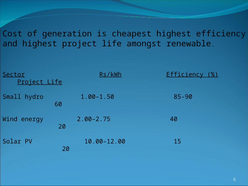
Cost of generation is cheapest highest efficiency and highest project life amongst renewable.
Sector Rs/kWh Efficiency (%) Project Life
Small hydro 1.00–1.50 85-90 60
Wind energy 2.00–2.75 40 20
Solar PV 10.00–12.00 15 20

7
• Maximum Demand Calculated is found to be 7.48 MW between 5 a.m. to 6 a.m.
• Plant Capacity Will be 10 MW. • IT consists of 2 Generating Units of 5 MW Capacity for the reliable supply of power.
• Use of Bulb Turbine for Low Heads and Efficiency.
About The Plant

8
Layout Of Power Plant

9
Bulb Turbine

10
Distribution System:
• Distributing Unit is used to supply the power to Industrial Area 1.
• Substation 1 is used to supply power Railway Station 2 & Railway Traction 2.
• Substation 2 is used to supply power to Rural Area.
• Substation 3 is used to supply power to Industrial Area 2, Business complex, Hospital, Railway Station 1 and Railways Traction .
•Substation 4 is used to supply power to School, Residential area, Street Lighting, Railway Station 1 and Railway traction.
•Two Railway Substations are used for the Traction Lines .

11
Position Of Sub Stations
•Substation 1 is taken near Power plant
•Substation 2 is taken for the Rural so near by it.
•Sustation 3 is taken near by Hospital since the availability of land.
•Substation 4 is taken near by School and Railway Traction And Station 1.

12
Protection Scheme
•Lightning Arrestor•Potential Transformer•Ground Switch•Isolator•Current Transformer•Circuit Breaker•Surge Divertor

13
Railway Traction
•Separate Substations For Traction•Subdivisioning Posts Are Used

Transformers Used
•132/11 Stepdown•66/11 Stepdown•66/132 Step up•66/33 Stepdown•11/.4 Stepdown

15
Switch Yard

16

17
Single Line Diagram of the Power Distribution System

18

19
Feeders From Power Plant & Distributing Unit

20

21
Sub Station 1
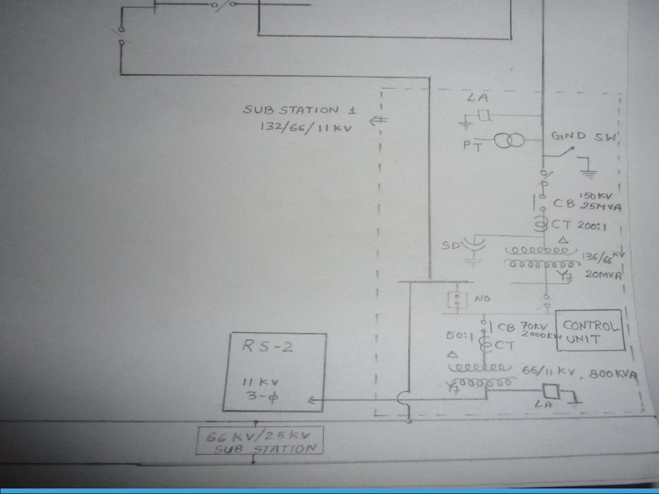
22

23
Sub Station 2

24

25
Sub Station 3

26

27
Sub Station 4

28

29
S No Name Rating Quantity
1 Transformer 66/11 KV 4
2 Transformer 132/11 KV 1
3 Transformer 11/.4 KV 4
4 Transformer 132/66 KV 1
5 Transformer 66/33 KV 1
6 Potential Transformer - 8
7 Current Transformer - 12
8 Circuit Breaker Varying 10
9 Isolator - 61
10 Lightening Arrestor - 16
11 Surge Diverter - 5
12 Unit Auxiliary Transformer 11/6.6 KV 2
13 Station Transformer 66/6.6 KV 1
Number of Equipments Used

30
References: •NITK 33/11 kV substation key diagram.
•Power system engineering by Soni,Gupta,Bhatnagar,hakrawarti.
•Power system protection and Switchgear by Badriram.
•Generation of electrical energy by B.R.Gupta.

31
THANK YOU

32
Queries ???