
Design, synthesis and applications of Metal Organic Frameworks
80
1 Design, synthesis and applications of Metal Organic Frameworks by Moqing Hu A Thesis Submitted to the Faculty of the Department of Chemistry and Biochemistry WORCESTER POLYTECHNIC INSTITUTE in partial fulfillment of the requirements for the Degree of Master of Science in Chemistry September 2, 2011 APPROVED: Prof. John C. MacDonald, Major Advisor
Transcript of Design, synthesis and applications of Metal Organic Frameworks

1
Design, synthesis and applications of Metal Organic Frameworks
by
Moqing Hu
A Thesis
Submitted to the Faculty
of the
Department of Chemistry and Biochemistry
WORCESTER POLYTECHNIC INSTITUTE
in partial fulfillment of the requirements for the
Degree of Master of Science
in
Chemistry
September 2, 2011
APPROVED:
Prof. John C. MacDonald, Major Advisor

2
Abstract
Porous materials have been a focus of researchers for their applications as molecular storage, molecular sensing, catalysis, asymmetric synthesis and host materials. Metal-organic frameworks (MOFs) represent a promising new class of porous crystalline solids because they exhibit large pore volumes, high surface areas, permanent porosity, high thermal stability, and feature open channels with tunable dimensions and topology. We are currently investigating the design, synthesis, and structures of a new family of MOFs derived from transition metals complexes of 4-(imidazole-1-yl)benzoic acids. Here we present our effort in continuing design and synthesis MOFs composed of 4-(imidazole-1-yl)benzoic acids to expand our knowledge about 4-(imidazole-1-yl)benzoic acid MOF family. A series of ligands are synthesized and Cu MOF-3N, 4, 5 and Cd MOF-3 were synthesized, structure determination found out metal-ligand complex follows our proposal, while Cu MOF-4,5 exhibit porous framework structure via absolute structure determination.
Sorption behavior is a key focus in MOF application because the great potential applications MOF bears. Here we carry out a fundamental study about MOF texture and selectivity on MOF-5 and Cd MOF-2. Non-polar polyaromatic hydrocarbons such as naphthalene, phenanthrene, and pyrene, polar molecules such as 2-naphthol, ibuprofen were selected to test our hypothesis that sorption is influenced by the degree of tight fitting, and guest-host interaction such as van der waals and hydrogen bonding. By determining Langmuir isotherms of selected guest molecules, we are able to demonstrate our hypothesis that tighter the fit of the guest molecule and the pores, the higher the amount it would sorb. The sorption difference of non-polar and polar molecules suggest hydrogen bonding is not involved in guest sorption and the dominating force of sorption is hydrophobic interaction.
Polymorphism is an interesting phenomenon that bears great value in pharmaceutical industry. Here we report the first case for MOF to serve as a heterogeneous surface that induced nucleation of indomethacin. It is also a first report of this polymorph form of indomethacin. PXRD, DSC, TGA, NMR are conducted as our initial investigation effort. This polymorph exhibits exceptionally thermal stability and low solubility, indicating an unusual tight binding between indomethacin and ethanol solvate.
3
Preface
I would like to deliver my gratitude to my advisor, Professor John C. MacDonald, at the moment I am delivering my master thesis. Professor MacDonald has been working with me for 3 years, who has shared his tremendous knowledge and his precious time with me. I really appreciate the effort and time he has put in to supervising my research and revising my thesis. I could not have finished my study and thesis if there was not his help.
I would like to thank WPI undergraduate student, Sahag Voskian, for working with me for 3 years, and contributing a lot to our group and an important part in my third chapter.
I would like to thank my colleague Pranoti Navare for her friendly help and company in the lab.
I am taking the chance to express my thank you to our instrument manager, Will Lin, for me with instrument help.
At last, I would love to thank our former department head, Kristin Wobbe, who was my department head during my graduate life for 3 years and has helped me out with problem, and our department, Department of Chemistry and Biochemistry, Worcester Polytechnic Institute for supporting me for my graduate study and research.

4
Table of contents
Abstract ........................................................................................................................................... 2
Preface ............................................................................................................................................. 3
Table of contents ............................................................................................................................. 4
List of figures ................................................................................................................................... 5
List of Tables .................................................................................................................................... 8
1. Overview ...................................................................................................................................... 9
1.1 Introduction ........................................................................................................................... 9
1.2 Background .......................................................................................................................... 12
1.3 Current research in the MacDonald group ......................................................................... 19
2. Design of Metal-Organic Frameworks Based on 4-(Imidazol-1-yl)benzoic Acids. ..................... 24
2.1. Strategy and Objectives ...................................................................................................... 24
2.2 Synthesis of ligands ............................................................................................................. 27
2.3 Hydrothermal synthesis of MOFs ........................................................................................ 34
2.4 Conclusion ........................................................................................................................... 49
3. Sorption Studies of Polyaromatic Hydrocarbons and Pharmaceuticals by MOFs ..................... 50
3.1 Introduction ......................................................................................................................... 50
3.2 Strategy................................................................................................................................ 51
3.3 Sorption of guest molecules ................................................................................................ 55
3.4 Conclusion ........................................................................................................................... 63
4. Surface-Induced Nucleation of a New Polymorph of Indomethacin on MOF-5 ....................... 64
4.1. Introduction ........................................................................................................................ 64
4.2 Background .......................................................................................................................... 64
4.3 Experimental ....................................................................................................................... 67
4.4 Conclusion ........................................................................................................................... 75
5. Conclusion ................................................................................................................................. 76
6. References ................................................................................................................................. 77

5
List of figures
Figure 1 View of the crystal structure of zeolite 4A looking down on the 4 Å wide channel (center). ......................................................................................................................................... 10 Figure 2. Different cage arrangements give rise to a range of pore sizes ..................................... 14 Figure 3. Assembly of metal−organic frameworks (MOFs) by the copolymerization of metal ions with organic linkers to give (a) flexible metal−bipyridine structures with expanded diamond topology and (b) rigid metal−carboxylate clusters that can be linked by benzene “struts” to form rigid extended frameworks in which the M−O−C core of each cluster acts as a large octahedron decorating a 6-connected vertex in a cube. All hydrogen atoms have been omitted for clarity. (In (a), M, orange; C, gray, N, blue; in (b), M, purple; O, red; C, gray. Structures were drawn using single-crystal X-ray diffraction data.)30 .......................................................................................... 15 Figure 4. The structure of MOF-5 showing the benzene-1,4-dicarboxylic acid linkers (top inset box) coordinated to zinc ion cluster joints (shown in blue in the bottom inset box). .................. 16 Figure 5. Comparison of the cubic structures of IRMOFs formed when linear aromatic dicarboxylic acids are reacted with Zn(II) ions. Top: Increasing the length of the aromatic dicarboxylic acid (highlighted in orange) gives IRMOFs with larger channels. Bottom: Introducing substituents (highlighted in maroon) onto benzene-1,4-dicarboxylic acid gives IRMOFs with cubic frameworks identical to that of MOF-5 (far left) in which the substituents protrude into the channels.17 ..................................................................................................................................... 17 Figure 6 Example of a porous, anisoreticular (non-cubic) MOF formed upon reaction of a 1:1 mixture of an aromatic dicarboxylic acid with an aromatic dipyridines in the presence of Zn(II) ions.20 ............................................................................................................................................. 19 Figure 7. Comparison between the structure of benzene-1,4-dicarboxylic acid and 4-(imidazoyl-1-yl)benzoic acid ligands. Coordination to metal ions occurs at the carboxylic acid (highlighted in orange) and imidazole (highlighted in blue) groups. Substituents can be introduced on the backbone of ligands by replacing hydrogen atoms (highlighted in red) with different organic groups. ........................................................................................................................................... 20 Figure 8. Synthetic strategy for preparing lower symmetry MOFs. Reaction of substituted 4-(imidazoyl-1-yl)benzoic acid ligands with Cu(II) or Cd(II) metal salts (left) potentially leads to octahedral coordination of the metal ions by carboxylate and imidazole groups in which the bonded ligands are oriented either in a square-planar (top center) or distorted tetrahedral (bottom center) arrangement. Further assembly of the square-planar and tetrahedral complexes produces MOFs with different framework architectures. Two possible frameworks are shown on the right. ........................................................................................................................................ 21 Figure 9. Views showing the crystal structures and channels present in Cd- and Cu-based MOFs synthesized in our group. .............................................................................................................. 22 Figure 10 View of the channels in Cu MOF-3 showing the location of methyl groups ( red circles) on the imidazole ring, hydrogen atoms (blue ovals) on the benzene ring, and the backbone of the benzene rings (orange rectangles). ......................................................................................... 25

6
Figure 11 Chemical structures of 4-(1,2,3-triazol-1-yl)benzoic acid (left) and 4-(imidazol-1-yl)benzoic acid (right). ................................................................................................................... 26 Figure 12 Chemical structures of ethyl 4-(2-ethylimidazolyl)benzoate, ethyl 4-(2-isopropylimidazolyl)benzoate and ethyl 4-(2-phenylimidazolyl)benzoate target ligands. .......... 28 Figure 13. Synthesis of ethyl 4-(2-ethyl-1H-imidazol-1yl)benzoate. ............................................. 28 Figure 14. Synthesis of ethyl 4-(2-isopropyl-1H-imidazol-1yl)benzoate. ...................................... 29 Figure 15. Synthesis of ethyl 4-(2-phenylimidazol-1-yl)benzoate. ................................................ 29 Figure 16 Chemical structures of 4-(4-butyl-1,2,3-triazol-1-yl)benzoic acid, 4-(4-phenyl-1,2,3-triazol-1-yl)benzoic acid, ethyl 4-(4-butyl-1,2,3-triazol-1-yl)benzoate, and ethyl 4-(4-phenyl-1,2,3-triazol-1-yl)benzoate target ligands. ............................................................................................. 31 Figure 17. Synthesis of ethyl 4-azidobenzoate .............................................................................. 31 Figure 18. Synthesis of ethyl 4-(4-butyl1,2,3-triazol-1-yl)benzoate. ............................................. 32 Figure 19. Synthesis of 4-azidobenzoic acid .................................................................................. 32 Figure 20. Synthesis of 4-(4-butyl1,2,3-triazol-1-yl)benzoic acid. ................................................. 33 Figure 21. Synthesis of 4-(4-phenyl-1H-1,2,3-triazol-1-yl)benzoic acid ........................................ 33 Figure 22. Synthesis of Cu MOF-3 ................................................................................................. 35 Figure 23. . Synthesis of Cu MOF-3N. The structure of the coordination complex is shown on the right. .............................................................................................................................................. 36 Figure 24. Schematic show of synthesis of Cu MOF-4 .................................................................. 36 Figure 25. synthesis of Cu MOF-5 .................................................................................................. 37 Figure 26. Synthesis of Cd MOF-3 ................................................................................................. 37 Figure 27 far left: square planer, middle left: tetrahedral distribution, middle right: square planer(trans), far right: square planer (cis) ................................................................................... 39 Figure 28 The spatial view of the Cu-ligand2 complex trans ......................................................... 40 Figure 29. The 2D network of one square planner layer (left) and 2D network with the other network penetrating (right)........................................................................................................... 40 Figure 30 Structure of Cu MOF-3N of one unit cell ....................................................................... 41 Figure 31 Cu MOF-3N loses approximate 3% of its mass up to 200 °C, demonstrating non-porous behavior ......................................................................................................................................... 41 Figure 32. Above: Crystal structure from the C axis of Cu MOF-4. Structure failed to show 50% of the second carbon on ethyl group on the imidazole ring due to the spatial uncertainty of the floppy ethyl group. Below: TGA curve of Cu MOF-4 as it gets heated at 10 °C per minite to 350 °C. At 100 °C it exhibits a loss of 30% of its mass; it lost a total of 35% before it decomposed. ....... 43 Figure 33. Above: Structure of Cu MOF-5, the grey balls in the void space indicate the amorphous yet still some anisotropy arrangement of the solvent molecules. Below: 4 layers of Cu MOF-5, one layer is highlighted in yellow ................................................................................ 45 Figure 34 Adamentine view of a single fold of framework of Cd MOF-2, which hides the other frameworks interpenetrate with this frame. ................................................................................ 46 Figure 35 The 4-fold interpenetration view of Cd MOF-1, different colors indicate one fold of framework. .................................................................................................................................... 47 Figure 36. Structure of 3-Cd, cadmium metal forms tetrahedral complex with coordination to 4 ligands ............................................................................................................................................ 48

7
Figure 37. 5-fold interpenetration in Cd MOF-3, Red, purple, light gree, blue and yellow each represents one fold of adamantine cage framework .................................................................... 48 Figure 38. Cap and stick (top) and space-filling (bottom) views of crystal structures and channels of MOF-5 and Cd MOF-2. .............................................................................................................. 53 Figure 39. Langmuir isotherm of naphthalene, phenanthrene and pyrene in MOF-5 (low concentration). .............................................................................................................................. 57 Figure 40. Sorption isotherm of 3 PAHs in Cd MOF-2 (low concentration) .................................. 58 Figure 41. Comparison of the number of moles of naphthalene (red) and phenanthrene (blue) sorbed by MOF-5. The numbers over column indicates folds of amount of selectivity. .............. 59 Figure 42. Sorption isotherm for 2-naphthol in MOF-5. ............................................................... 60 Figure 43. Langmuir isotherm for sorption of ibuprofen by MOF-5 ............................................. 61 Figure 44 Langmuir isotherm for sorption of phenanthrene by MOF-5 (higher concentration) .. 62 Figure 45 Images of crystals of IMCEattached to the surface of MOF-5. ...................................... 68 Figure 46. PXRD traces for IMC and IMCE. Black trace: IMC Form I. Blue trace: IMC obtained from fast evaporation method. Red trace: IMCE. ........................................................................ 68 Figure 47. TGA traces of Indomethacin and Indomethacin ethanol solvate ................................. 71 Figure 48. DSC traces of IMC polymorphs and IMCE..................................................................... 72 Figure 49. IR spectra of IMC and IMCE polymorphs. Blue: IMC form I, Red: IMC mixture of form I and II, and Brown: IMC ethanol solvate. ....................................................................................... 73

8
List of Tables
Table 1. International Union of Pure and Applied Chemistry (IUPAC) classifications of porous materials.24 .................................................................................................................................... 13 Table 2. Crystallographic data of Cu MOF-3N, 4, 5 and Cd MOF-3 ............................................... 39 Table 3 Crystallographic data of Cu MOF-3 and Cu MOF-4 ........................................................... 42 Table 4. Chemical structures, formulas, molecular weights, and molecular dimensions for naphthalene, phenanthrene, and pyrene. .................................................................................... 54 Table 5. Chemical structures, formulas, molecular weights, and molecular dimensions for 2-napthol and ibuprofen. ................................................................................................................. 54 Table 6. Langmuir model constants for the sorption of three PAHs by MOF-5 and the R2 value (calculated by plotting equation 2). .............................................................................................. 57 Table 7. Linear model constants for the sorption of three PAHs by MOF-5 and the R2 value. ..... 57 Table 8. Langmuir model constants for the sorption of three PAHs by Cd MOF-2 and the R2 value. ....................................................................................................................................................... 58 Table 9 Langmuir model constants for the sorption of ibuprofen by MOF-5 and the R2 value .... 61 Table 10 Langmuir model constants for the sorption of phenanthrene (obtained at higher concentration) by MOF-5 and the R2 value ................................................................................... 62 Table 11. Growing of crystals in various conditions ...................................................................... 74

9
1. Overview
1.1 Introduction
Porous solids have received long-standing interest in the scientific community due to their suitability as host materials for molecular separation and storage1, molecular sensing2,3, catalysis4,5, asymmetric synthesis,6 and as host templates for preparing composite materials (e.g., organic/inorganic templates for embedded arrays of nanowires/polymers etc).7-9 Porous solids can be classified broadly in two categories: amorphous solids and ordered (i.e., crystalline) solids. Plastics and gels are two common examples of solids that often are porous and do not exhibit ordered repeated units within their structures.10,11 Nanoporous silica and zeolites are representative examples of ordered porous solids with defined, repeating crystalline structures. Amorphous solids can be advantageous to work with as materials because they usually are inexpensive, easy to process, and can be prepared from a wide variety of different chemical constituents. Disadvantages arising from structural disorder present in amorphous porous solids include that their structures often are difficult to characterize, the solids frequently exhibit a range of molecular architectures with variable channel structures and topologies that are not easily predicted, reduced void volumes due to trapping of monomers and oligomers within channels during synthesis, and low mechanical stability due to the lack of long-range order.12 In contrast, ordered porous solids such as zeolites and mesoporous silica have structures that generally can be characterized by X-ray diffraction, feature pores/channels with topologies and dimensions that are reproducible and have high mechanical and thermal stability.6 Our research has focused solely on order porous solids to take advantage of those properties.
Within the class of ordered porous solids, zeolites have been the most widely studied. Zeolites are naturally occurring porous inorganic aluminosilicate minerals referred to as molecular sieves that are used commercially for applications in molecular adsorption, separation and removal.13-15 For example, zeolite 4A (Na12Al12Si12O48) forms a porous solid permeated by channels 4 Å in diameter resulting from 8 tetrahedrally coordinated silicon/aluminum atoms and 8 oxygen atoms. Zeolite 4 Å commonly is used as a drying agent due to the size-selective specificity and hydrophilic nature of the channels for absorbing water, the high loading capacity of the bulk material, and the ability to reactivate the zeolite once it becomes saturated by removing the absorbed water at elevated temperatures. The structure of zeolite 4A is shown in Figure 1. Another application of zeolites as porous sorbants was demonstrated when silicalite-1 was used to remove gasoline from drinking water.16 Despite their widespread use, zeolites have several potential drawbacks that limit their utility as porous solids. Those drawbacks

10
include syntheses that can be difficult to control, a limited number of structural and channel architectures that are available, and crystalline structures based on covalently-bonded networks of atoms that cannot be modified easily to vary the structures, topologies or properties of channels without altering the structure of the zeolite.
Figure 1 View of the crystal structure of zeolite 4A looking down on the 4 Å wide channel (center).
A new class of ordered porous solids called metal-organic frameworks (MOFs), or porous coordination polymers, was discovered almost two decades ago. MOFs are considered organic analogs of inorganic zeolites in which oxygen atoms are replaced by rigid organic ligands that bridge the metal ions. The resulting crystalline solids are comprised of rigid frameworks of molecules coordinated to metal ions in two or three dimensions that form open networks that render the crystalline structure highly porous. MOFs represent a promising new class of porous crystalline solids because they exhibit some of the largest pore volumes and highest surface areas known. In most cases, MOFs also exhibit permanent porosity and high thermal stability to above 300 °C. MOFs have attracted the attention of researchers largely because they offer several significant advantages over zeolites resulting from the organic ligands present in the backbone of the framework—namely, the dimensions and properties (e.g., hydrophobicity, exposed functionality, reactivity, etc.) of channels can be controlled at the molecular level via synthetic modification of the ligand either before or after the MOF is prepared.17-19 Consequently, the structures and physical properties of MOFs can be controlled to a far greater extent relative to zeolites. In addition, the void volumes and diameters of channels in some MOFs (i.e., up to 29 Å) far exceed those observed in the most highly porous zeolites, which allows small to medium sized organic compounds both to diffuse through channels and to be covalently appended to reactive groups on the walls of channels.19
Fifteen years ago, Yaghi demonstrated MOFs derived from benzene-1,4-dicarboxylic acid and many substituted derivatives of the parent ligand coordinated to tetradral clusters

11
of zinc ions share a common highly symmetric cubic framework structure referred to as an isoreticular MOF, or IRMOF, that persists across a large family of those ligands.17 IRMOFs subsequently were shown to exhibit remarkable thermal stability to temperatures greater than 400 °C, maintain permanent porosity when guest solvent was removed, reversible sorption/desorption of molecular guests, and high mechanical stability. Since then, the majority of MOFs reported exhibit highly symmetric framework structures (e.g., cubic) that result from the use of rigid, symmetric aromatic di- or tricarboxylic acids, or mixtures of dicarboxylic acids and dipyridines as the organic linkers.20
We recently began a program of exploratory research toward developing a new family of porous MOFs consisting of 4-(imazol-1-yl)benzoic acids coordinated to transition metal ions such as Cd(II) and Cu(II). Our motivation has been to establish a new paradigm for constructing MOF solids that do not rely solely on carboxylic acids to drive molecular assembly, and to investigate using lower-symmetry, bent ligands to generate MOFs with lower-symmetries than the cubic structures observed in MOFs derived from metal di- and tricarboxylates. Our initial efforts in that regard have produced several novel lower symmetry Cd(II)- and Cu(II)-based MOFs exhibiting permanent porosity and thermal stability.
The research described here has focused in three areas related to the continued development of lower symmetry MOFs—namely synthesis of new ligands to expand the library of molecular building blocks for constructing MOFs as well as synthesis of MOFs from those ligands, investigation of several MOF systems to characterize their porous behavior with respect to sorption of organic guests such as polyaromatic hydrocarbons and pharmaceutical drugs, and investigation of a known IRMOF to act as a surface template that induces growth of a previously unreported ethanol solvate of the drug indomethacin.
The sections that follow in Chapter 1 provide background information on relevant research on ordered porous solids reported by others. Following that, we describe our reasoning and design strategy for MOFs based on 4-(imazol-1-yl)benzoic acid and substituted derivatives. The results of previous work in our group to develop MOFs based on 4-(imazol-1-yl)benzoic acids also is described.
Chapter 2 describes the results of our efforts to synthesize new ligands as building blocks for MOFs, and to synthesize and characterize new MOF structures. The major aim of this work was to expand our library of derivatives of 4-(imazol-1-yl)benzoic acid and to explore developing a new family of structurally related ligands of substituted derivatives of1,2,3-triazole utilizing click chemistry.

12
Chapter 3 describes work carried out to investigate the sorption behavior of a known IRMOF and one of our Cd-based MOFs toward nonpolar polyaromatic hydrocarbons and polar pharmaceutical drugs.
In Chapter 4, we report preliminary efforts to investigate surface-induced nucleation and growth of a new crystalline form of the pharmaceutical drug indomethacin on solid particles of IRMOF-5. This research demonstrates for the first time that a porous MOF can serve as a heterogeneous surface to promote crystallization of a new polymorphic form of a drug.
1.2 Background
Porous solids. Solids featuring pores or channels with dimensions large enough to admit and allow diffusion of guest molecules are referred as porous solids. Most porous solids have porosities ranging from 0.2 to 0.95, defined by the fraction of void volume accessible to guests to the total volume occupied by the solid material itself. Porous solids are ubiquitous and utilized widely in many domestic, commercial or industry applications.21 Porous solids have attracted the attention of scientists due to their potential as materials for storing, separating, and sensing molecular guests, as well as for their unique ability to act as host materials to promote organic reactions and act as heterogeneous catalysts.22 For example, activated carbon, a traditional porous solid whose ability to sorb organic molecules has been recognized for more than a century, has many broad applications spanning from household odor removers to a range of industrial processes requiring absorption and removal of organic contaminants.
Ordered porous solids. Porous solids can be divided into two broad classes. Disordered porous solids such as organic polymers have largely random structures exhibiting cavities or channels with dimensions that vary greatly such that neither their structures nor their porosity can be characterized easily due to the lack of defined structure. Although the porosity of disordered porous materials can be modified synthetically, the dimensions and patterns of microscopic pores generally are difficult to reproduce.23 Ordered porous solids differ from disordered porous solids in that they feature well-defined pore structures, dimensions and topologies that can be controlled and reproduced reliably, and that can be characterized unambiguously using techniques such as X-ray diffraction, AFM, etc. Zeolites and metal-organic frameworks (MOFs) are two well known examples of ordered porous solids that have been widely studied. Porous solids can be further classified as macroporous, mesoporous, or microporous materials on the basis of the diameter of pores. The IUPAC requirements with respect to the diameter of pores for classification under those three categories are shown in Table 1.

13
Table 1. International Union of Pure and Applied Chemistry (IUPAC) classifications of porous materials.24
Material Terms Diameter of pores Macroporous materials >50nm Mesoporous materials In between 2nm to 50nm Microporous materials <2nm
The hallmark of zeolites and MOFs is that their structures are permeated by continuous networks of channels, sometimes referred to as pores, that permeate the crystalline structure. The width of channels in zeolites typically span a range of sizes ranging from 3-12 Å, while those in MOFs often tend to be larger, ranging in size from a small as 4 Å to as large as 29 Å. In cases where the width of channels is large enough to admit organic guests, the molecules generally are able to diffuse throughout the porous host. The ability of guests to diffuse freely depends not only on the size of the openings of channels, but also on the topology of channels, the incidence of steric constrictions, and intermolecular interaction of the guests with functionality present in the walls of channels. As such, the dynamics of host-guest interaction and equilibria of diffusion are unique to each porous solid and define their porous behavior.
Zeolites. Zeolites are microporous crystalline aluminosilicates, composed of TO4 tetrahedra (T=Si or Al) bonded to oxygen atoms to form a sodalite cage, or β-cage, that is the basic building block of zeolites. As shown in Figure 2, zeolites with a range of structures and channel topologies (e.g., SOD, LTA, FAU, EMT) can be constructed from different arrangements of the sodalite cage in which oxygen atoms connect the neighboring cages.24 When all T positions are occupied by Si atoms, the resulting solid is uncharged silica. Substitution of Al for Si atoms necessarily introduces one negative charge per Al atom and requires the presence of cations in the channels to balance the negative charge. A beneficial consequence of the presence of cations within the channels is that zeolites can be use for applications involving exchange of ions. For example, zeolites commonly are used as additives in laundry detergents to soften hard water by taking up hard ions such as Ca2+ and Mg2+ and releasing softer Na+ ions.25

14
Figure 2. Different cage arrangements give rise to a range of pore sizes
Upon discovery of naturally occurring zeolites, initial efforts to synthesize zeolites focused largely on strategies involving hydrothermal crystallization using a silica source, an aluminum source and alkali hydroxide.26,27 Since then, a number of synthetic methods such as the modified hydrothermal method, the solvothermal method and the low temperature gel method have been employed to synthesize different zeolites.13,28 To date, almost 200 unique zeolite framework structures have been identified according to database of zeolites structures. The range of pore dimensions for zeolites spans from 0.2 to 0.8 nm, and pore volumes vary from 0.10 to 0.35 cm3/g. By varying the ratio of aluminum and silicon, it has been demonstrated that the hydrophobicity of the channels can be tuned.16 Accordingly, zeolites are widely used for chemical processes and applications involving separation of gases, heterogeneous catalysis, and ion exchange for smaller molecules that fall within the range of accessible pore diameters.13,24
Metal-organic frameworks (MOFs). MOFs are a relatively new class of ordered porous solids that have been investigated the past 15 years. MOFs are crystalline coordination polymers composed of inorganic ions or ion clusters and organic linkers, forming soluble complexes that then self-assemble into one-, two-, or three-dimensional frameworks. The advantage of this class of materials is that by carefully choosing metal ions and organic ligands, it is possible to tailor the structures and sizes of pores within MOFs by design. Because of the wide variety of coordination geometries offered by transition and lanthanide metal ions and the rich number of structures and reactive functionalities that can be incorporated into organic linkers via organic synthesis, MOFs provide a means to generate a diverse range of framework architectures. As shown in Figure 3, tetrahedral coordination of a linear dipyridine to a central metal ion produces a diamond framework (Figure 3a), while octahedral coordination around a tetrahedral cluster of metal ions results a cubic framework (Figure 3b). A characteristic feature of MOFs is their

15
extremely high surface areas and void volumes and pore openings ranging from 3 Å up to 20 Å that are highly accessible to organic guests.29 As such, MOFs represent a unique class of ordered porous materials that have great potential as hosts in applications that require pore dimensions that exceed those of zeolites.
Figure 3. Assembly of metal−organic frameworks (MOFs) by the copolymerization of metal ions with organic linkers to give (a) flexible metal−bipyridine structures with expanded diamond topology and (b) rigid metal−carboxylate clusters that can be linked by benzene “struts” to form rigid extended frameworks in which the M−O−C core of each cluster acts as a large octahedron decorating a 6-connected vertex in a cube. All hydrogen atoms have been omitted for clarity. (In (a), M, orange; C, gray, N, blue; in (b), M, purple; O, red; C, gray. Structures were drawn using single-crystal X-ray diffraction data.)30
High-symmetry MOFs based on benzene-1,4-dicarboxylic acids. MOF-5 developed by Yaghi’s group is the most well-known example of a stable, highly porous MOF. MOF-5 (isoreticular metal-organic framework-1, IRMOF-1) was first reported in 1999 and quickly became the most intensively studied MOF. As shown in Figure 4, MOF-5 is composed of benzene-1,4-dicarboxylic acid (BDC) linkers octahedrally coordinated to tetrahedral Zn4O clusters to form a cubic framework with the formula Zn4(BDC)3O. The MOF-5 cubic framework, after activation by removing solvent by heating, has a remarkably high internal surface area of 4500m2/g.29

16
Tunability of the IRMOF framework. One of the principle advantages of MOFs over zeolites is that the dimensions and topology of channels can be tuned through organic synthesis by modifying the molecular structure of the organic ligands that bridge the metal ions. Another advantage is that the surface properties of channels can be altered by appending different organic substituents onto the organic ligand without changing the architecture of the framework.17 Based on that concept, a number of IRMOFs have been developed that preserve the isoreticular cubic structure of MOF-5 and that feature substituents protruding off the benzene backbone into the void space of channels, as shown in Figure 5. For example, Yaghi has shown that the dimensions of the cubic cages present in MOF-5, and thus the corresponding void volumes, can be expanded by substituting linear naphthyl, biphenyl, pyrene or triphenyl dicarboxylic acids in place of benzene-1,4-dicarboxylic acid (orange boxes in Figure 5) without altering the overall connectivity or cubic structure of the resulting MOFs.17 Substituted benzene-1,4-dicarboxylic acids also were used to introduce polar and nonpolar functional groups that projected into the cavities. Substituting polar substituents (maroon circles in Figure 5) such as bromine or amine groups, or nonpolar hydrocarbon groups such as fused benzene or cyclobutane groups in place of one or two hydrogen atoms on the benzene backbone resulted in IRMOFs with channels that were more hydrophilic or hydrophobic, respectively, than those in MOF-5.17
Figure 4. The structure of MOF-5 showing the benzene-1,4-dicarboxylic acid linkers (top inset box) coordinated to zinc ion cluster joints (shown in blue in the bottom inset box).

17
Figure 5. Comparison of the cubic structures of IRMOFs formed when linear aromatic dicarboxylic acids are reacted with Zn(II) ions. Top: Increasing the length of the aromatic dicarboxylic acid (highlighted in orange) gives IRMOFs with larger channels. Bottom: Introducing substituents (highlighted in maroon) onto benzene-1,4-dicarboxylic acid gives IRMOFs with cubic frameworks identical to that of MOF-5 (far left) in which the substituents protrude into the channels.17
In addition to the molecular structure of the organic ligand, the type of metal ions and coordination geometry around the metal ions plays a critical role in defining the architecture of MOFs. The vast majority of reported MOFs feature frameworks containing transition metal ions that contain ligands bound via linear, tetrahedral, square planar, or octahedral coordination geometries, while MOFs derived from lanthanide metal ions exhibit higher degrees of coordination with up to nine ligands bound to the metal ions.31 The ability to tune the framework architectures and properties in MOFs via the ligand and the metal ion provides a significant advantage over the zeolites because essentially an infinite number of variations can be constructed with framework structures that generally are predictable. Despite the relatively high thermal stability of MOFs of up to 400°C, MOFs cannot compete with the thermal stability of zeolites, which often are stable to temperatures above 1200 °C.24 Nonetheless, MOFs show remarkable thermal stability for organic materials that make them suitable as porous hosts for applications that do not require high temperature.
During the last decade, approximately 2200 papers describing research on MOFs have appeared in the literature. The majority of those articles have focused on synthesis in order to develop a robust library of MOF synthetic methodology necessary to begin exploring the properties of MOFs. The materials community only now is just beginning to fully explore the broader utility of MOFs as porous hosts. Although reports

18
investigating the applications of MOFs are now beginning to appear, the porous behavior of MOFs remains largely undefined and presents fertile ground for further investigation.
Applications of MOFs. With the advent of a large body of synthetic protocols for preparing MOFs, researchers are now exploring the host-guest behavior of MOFs in many areas of chemistry, with the vast majority of applications focusing on the sorption behavior of isoreticular MOFs. Yaghi and others are developing IRMOFs as host materials for energy storage.32 For example, it has been shown that MOFs are able to store high densities of hydrogen under relatively moderate pressures in steel cylinders packed with those materials.33 The high accessible void volume MOFs provide make them one of the more promising materials to meet hydrogen storage standards set by the DOE.34 Similar to zeolites, the utility of MOFs in heterogeneous catalysis has also been explored. MOFs offer the added advantage of having an organic component that can be tailored to accommodate a range of reactive groups that can actively or passively participate in catalysis.35 For example, Hasegawa et al created a 3-D porous coordination polymer that functionalized with amide groups that have demonstrated its ability to catalyze Knoevenagel condensation. 36 MOFs can also serve as nanoreactors that provide unique phases in which to carry out organic reactions where the large channels of MOFs serve as nanoscale containers for reactants and transition states that are too sterically demanding to fit within zeolites channels.37 Sabo et al have demonstrated MOF-5 can serve as palladium substrate that enable catalysis of styrene in cavities within MOF-5. 38 Because MOFs are biodegradable, they also are being studied as container materials for drug delivery.39 Horcajada et al have demonstrated MIL-53’s ability for controlled release vehicle for drug ibuprofen.40 Furthermore, MOFs with chiral framework architectures have been shown to catalyze reactions enantioselectively.41,42 For example, chiral secondary alcohols were generated by a chiral MOF in very high yields and enantioselectivities. Wu and Lin reported a case in which the addition of diethylzinc to 1-naphthaldehyde was catalyzed to afford (R)-1-(1-naphthyl)-propanol with complete conversion and 90.0% ee. 42 Molecular sorption of larger organic guests is an additional area where the large surface areas, pore dimensions and high porosities of MOFs provide unique opportunities as sorbants for environmental remediation and purification. For example, MOFs have shown superior sorption behavior toward TBME (additive in gasoline) and estrone (a hormone used for birth control) present in water when compared to industrial sorbants such as activated carbon. 16 43 Other applications of MOFs that have explored include molecular separation, molecular sensing and nanofabrication.6
Lower-symmetry MOFs. The majority of reported MOFs have isoreticular cubic frameworks; Yaghi’s IRMOFs are the classical examples. The design of MOFs with non-cubic structures is now being investigated in an effort to expand the library of framework architectures that are available and determine whether MOFs with lower symmetries exhibit unique porous properties. Efforts to produce stable MOFs with lower symmetry
19
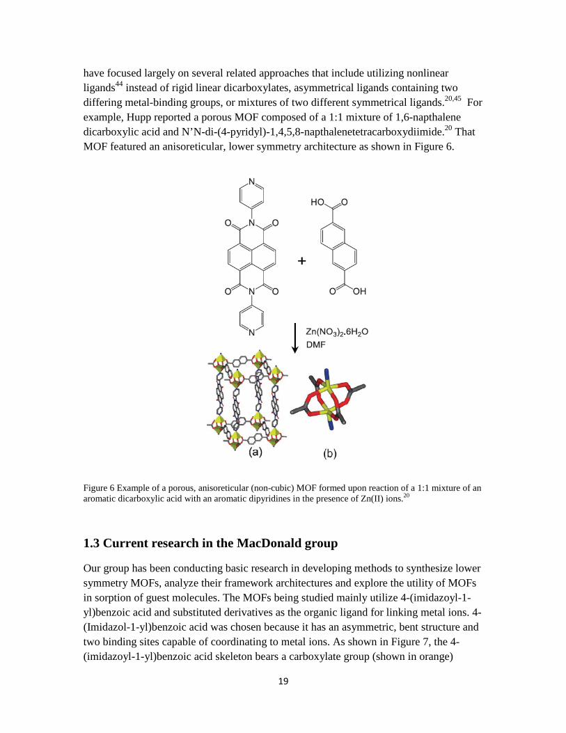
have focused largely on several related approaches that include utilizing nonlinear ligands44 instead of rigid linear dicarboxylates, asymmetrical ligands containing two differing metal-binding groups, or mixtures of two different symmetrical ligands.20,45 For example, Hupp reported a porous MOF composed of a 1:1 mixture of 1,6-napthalene dicarboxylic acid and N’N-di-(4-pyridyl)-1,4,5,8-napthalenetetracarboxydiimide.20 That MOF featured an anisoreticular, lower symmetry architecture as shown in Figure 6.
Figure 6 Example of a porous, anisoreticular (non-cubic) MOF formed upon reaction of a 1:1 mixture of an aromatic dicarboxylic acid with an aromatic dipyridines in the presence of Zn(II) ions.20
1.3 Current research in the MacDonald group
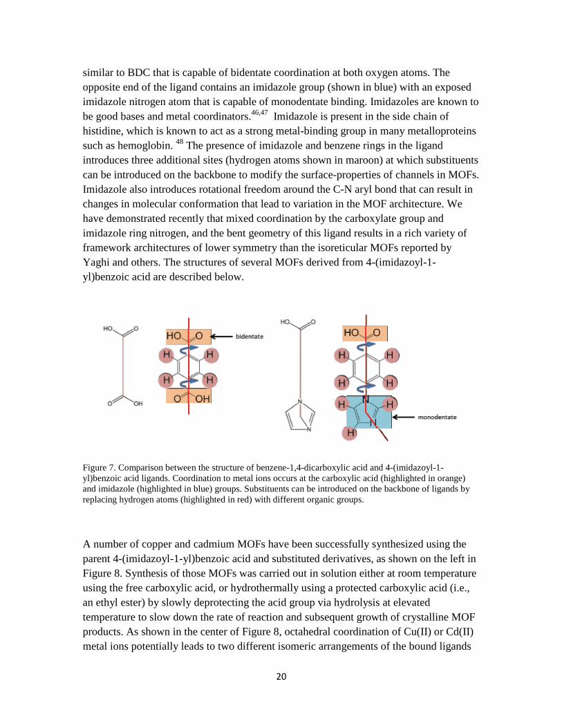
Our group has been conducting basic research in developing methods to synthesize lower symmetry MOFs, analyze their framework architectures and explore the utility of MOFs in sorption of guest molecules. The MOFs being studied mainly utilize 4-(imidazoyl-1-yl)benzoic acid and substituted derivatives as the organic ligand for linking metal ions. 4-(Imidazol-1-yl)benzoic acid was chosen because it has an asymmetric, bent structure and two binding sites capable of coordinating to metal ions. As shown in Figure 7, the 4-(imidazoyl-1-yl)benzoic acid skeleton bears a carboxylate group (shown in orange)
20
similar to BDC that is capable of bidentate coordination at both oxygen atoms. The opposite end of the ligand contains an imidazole group (shown in blue) with an exposed imidazole nitrogen atom that is capable of monodentate binding. Imidazoles are known to be good bases and metal coordinators.46,47 Imidazole is present in the side chain of histidine, which is known to act as a strong metal-binding group in many metalloproteins such as hemoglobin. 48 The presence of imidazole and benzene rings in the ligand introduces three additional sites (hydrogen atoms shown in maroon) at which substituents can be introduced on the backbone to modify the surface-properties of channels in MOFs. Imidazole also introduces rotational freedom around the C-N aryl bond that can result in changes in molecular conformation that lead to variation in the MOF architecture. We have demonstrated recently that mixed coordination by the carboxylate group and imidazole ring nitrogen, and the bent geometry of this ligand results in a rich variety of framework architectures of lower symmetry than the isoreticular MOFs reported by Yaghi and others. The structures of several MOFs derived from 4-(imidazoyl-1-yl)benzoic acid are described below.
Figure 7. Comparison between the structure of benzene-1,4-dicarboxylic acid and 4-(imidazoyl-1-yl)benzoic acid ligands. Coordination to metal ions occurs at the carboxylic acid (highlighted in orange) and imidazole (highlighted in blue) groups. Substituents can be introduced on the backbone of ligands by replacing hydrogen atoms (highlighted in red) with different organic groups.
A number of copper and cadmium MOFs have been successfully synthesized using the parent 4-(imidazoyl-1-yl)benzoic acid and substituted derivatives, as shown on the left in Figure 8. Synthesis of those MOFs was carried out in solution either at room temperature using the free carboxylic acid, or hydrothermally using a protected carboxylic acid (i.e., an ethyl ester) by slowly deprotecting the acid group via hydrolysis at elevated temperature to slow down the rate of reaction and subsequent growth of crystalline MOF products. As shown in the center of Figure 8, octahedral coordination of Cu(II) or Cd(II) metal ions potentially leads to two different isomeric arrangements of the bound ligands

21
in which the ligands were oriented either in a square-planar or a distorted tetrahedral arrangement. Those coordination motifs can produce a range of frameworks with different connectivity in two or three dimensions, two of which are illustrated schematically on the right in Figure 8.
Figure 8. Synthetic strategy for preparing lower symmetry MOFs. Reaction of substituted 4-(imidazoyl-1-yl)benzoic acid ligands with Cu(II) or Cd(II) metal salts (left) potentially leads to octahedral coordination of the metal ions by carboxylate and imidazole groups in which the bonded ligands are oriented either in a square-planar (top center) or distorted tetrahedral (bottom center) arrangement. Further assembly of the square-planar and tetrahedral complexes produces MOFs with different framework architectures. Two possible frameworks are shown on the right.
Shown in Figure 9, the crystal structures of two Cd(II)-based MOFs (i.e., Cd MOF-1 and Cd MOF-2) and three Cu(II)-based MOFs (i.e., Cu MOF-1, Cu MOF-2 and Cu MOF-3) we have prepared all feature non-cubic frameworks that exhibit permanent porosity resulting from large channels (up to 12 Å in diameter) that permeate the MOF structures. Reversible porosity of all MOFs was further confirmed by thermogravimetric analysis (TGA) to measure the percentage of weight loss of guest solvents . Guests consisting of molecules of water and ethanol that were included in the framework during synthesis accounted for 12-30% loss in mass when samples of MOFs were heated, demonstrating porosity comparable to that reported for IRMOFs. The non-cubic architectures of the MOFs shown in Figure 9 exhibit connectivity in two (Cu MOF-2) or three (Cd MOF-1, Cd MOF-2, Cu MOF-1 and Cu MOF-3) dimensions that results in part due to the bent nature of the ligands and the resulting mixed coordination geometries of the carboxylate and imidazole groups around the central metal ions.

22
Figure 9. Views showing the crystal structures and channels present in Cd- and Cu-based MOFs synthesized in our group.
Of the structures shown, Cu MOF-3 demonstrated the highest level of porosity (30% weight loss) resulting from the presence of large helical channels. Coordination of Cu ions by 4-(2-methylimidazol-1-yl)benzoic acid in Cu MOF-3 was somewhat unusual in that the methyl groups on the imidazole ring close to the coordination centers created significant steric hindrance that forced the carboxylates to behave as monodentate rather than bidentate ligands. Monodentate binding of the two carboxylates and two imidazole groups resulted in square-planar coordination with the four attached ligands bending to one side of the square plane. That arrangement produced a hexagonal helical framework with channels 12 Å in diameter. The structure of Cu MOF-3 is of particular interest for the following reasons: 1) it exhibits the highest porosity of the MOFs obtained; 2) it offers an unusual chiral helical channel; and 3) the methyl substituents on imidazole present at the surface of the channel potentially provide sites at which different organic

23
groups may be introduced to modify the surface properties of the channels without disturbing the framework structure. In Chapter 2, we carry out the synthesis of several derivatives of 4-(2-methylimidazol-1-yl)benzoic acid containing larger substitutents at the 2-position of imidazole to test our hypothesis (3, above) and describe the structures and porous behavior of new Cu-based MOFs derived from those ligands. In Chapter 3, we also describe a series of sorption experiments in which we investigated the affinity and sorption characteristics of our MOF systems and Yaghi’s IRMOF-5 toward small libraries of polyaromatic hydrocarbons and pharmaceutical drugs.

24
2. Design of Metal-Organic Frameworks Based on 4-(Imidazol-1-yl)benzoic Acids.
2.1. Strategy and Objectives
Ligands based on 4-(Imidazol-1-yl)benzoic acids. As described in the background section in Chapter 1, five different MOFs comprised of 4-(imidazole-1-yl)benzoic acid ligands coordinated to Cd(II) or Cu(II) ions were prepared previously in our group and the crystal structures and thermal properties were investigated. An important aim of that study was to determine if mixed binding by carboxylate and imidazole groups would promote fully saturated octahedral coordination at the central metal ion (i.e., by four oxygen and two nitrogen atoms) leading to square-planar or distorted tetrahedral arrangements of the attached ligands, as illustrated in Figure 8. Analysis of the crystal structures (Figure 9) revealed several important findings, the first of which was that 4-(imidazole-1-yl)benzoic acids fully saturate Cd(II) via octahedral coordination resulting in distorted tetrahedral arrangements of the ligands, while fully saturated (i.e., octahedral) or partially saturated (i.e., square-planar) coordination to Cu(II) both led to square-planar arrangements of the ligands. Those results suggested that the structure of the complex that serves as the molecular building block, and thus the corresponding geometry (i.e., tetrahedral vs square-planar) around the metal centers within the MOF framework, can be controlled based on the choice of metal ion.
A second important finding was that introducing a methyl alkyl substituent at the 2-position on the imidazole ring introduced a steric bias for square-planar assembly of the ligands with the carboxylate and imidazole groups oriented all to one side of the square plane. As a direct consequence of that coordination geometry and the bent nature 4-(2-methylimidazol-1-yl)benzoic acid, the ligands formed large helical channels in the structure of Cu MOF-3. The observation that imidazole rings in the unsubstituted parent ligand were oriented on opposite sides of the square plane in Cu MOF-1 and Cu MOF-2 (Figure 9) further suggested that formation of the Cu MOF-3 framework depends on the presence of a substituent at the 2-position of imidazole.
A view of the channels in the crystal structure of Cu MOF-3 showing the location of the methyl groups, imidazole and benzene rings, and the positions of hydrogen substitutents on the rings is shown in Figure 10. In that structure, the imidazole groups stack such that the methyl groups (highlighted by red circles in Figure 10) protrude slightly into the channels. On the basis of that observation, we anticipated that replacing the methyl substituent with longer or more sterically demanding alkyl or aryl groups (e.g., ethyl, propyl, isopropyl, phenyl, etc.) should preserve the Cu MOF-3 structure, while allowing the substituents to dangle farther into the channels. Such an approach would provide a means to generate additional Cu-based MOFs with architectures similar to Cu MOF-3.

25
We reasoned that development of an isomorphous family of MOFs with a common framework would enable the hydrophobicity of the channels to be tailored to favor sorption of hydrophobic guests by decorating the walls of the channels with nonpolar hydrocarbon groups. In addition, the observation that hydrogen atoms on the benzene rings also are exposed at the edges of channels in Cu MOF-3 (highlighted by blue ovals in Figure 10) suggested that a similar approach might be used to modify the hydrophobicity of MOFs by introducing substituents at other positions along the backbone of the ligand.
Figure 10 View of the channels in Cu MOF-3 showing the location of methyl groups ( red circles) on the imidazole ring, hydrogen atoms (blue ovals) on the benzene ring, and the backbone of the benzene rings (orange rectangles).
Consequently, a major objective of the research described in this Chapter was to synthesize new derivatives of 4-(imidazole-1-yl)benzoic acid by introducing simple alkyl substituents onto the imidazole and benzene rings, and then synthesize the corresponding MOFs, and characterize their structures and porosity to test our hypothesis that the structure of Cu MOF-3 would be preserved. That goal is part of a larger effort in our group to expand the library of ligands based on 4-(imidazole-1-yl)benzoic that can be used to construct MOFs, and to establish the molecular parameters necessary to develop families of MOFs with structures and properties that can be predicted a priori.
Ligands based on 4-(1,2,3-triazol-1-yl)benzoic acids. In addition to the work on 4-(imidazol-1-yl)benzoic acids, we describe our initial efforts to synthesize a different family of ligands in which imidazole was replaced by a 1,2,3-triazole ring. We chose to

26
explore using 4-(1,2,3-triazol-1-yl)benzoic acids as ligands for contructing MOFs because 4-(1,2,3-triazol-1-yl)benzoic acid is similar structurally to 4-(imidazol-1-yl)benzoic acid, the only difference being that the CH group on imidazole is replaced by a nitrogen atom, as shown in Figure 11. A survey of the Cambridge Structural Database (CSD)49-53 revealed several metal complexes with 1,2,3-triazole structure by click chemistry preparation. Analysis of coordination of those complexes to metal ions showed that 4-(1,2,3-triazol-1-yl)benzoic acid is capable of binding to metal ions at the ring nitrogen at position 3 in a manner similar to 4-(imidazol-1-yl)benzoic acid. The fact that the nitrogen atom at position 2 did not participate in binding to metal ions suggested either that that nitrogen has less electron density and is not as basic, or that the close proximity to the C-N bond to benzene sterically inhibits coordination of metal ions at that site. Given that the nitrogen at position 2 has a lone pair of electrons instead of a hydrogen or alkyl substituent, we anticipated that the 1,2,3-triazole ring should behave similar sterically to unsubstituted imidazole with regard to coordinating to metal ions at position 3. The small set of structures of 1,2,3-triazole metal complexes observed in the CSD appeared to support that hypothesis in that coordination was observed only to the ring nitrogen at position 3.
Figure 11 Chemical structures of 4-(1,2,3-triazol-1-yl)benzoic acid (left) and 4-(imidazol-1-yl)benzoic acid (right).
One of our principle motivations for exploring the utility of 1,2,3-triazoles as isomorphous building blocks to imidazoles for constructing MOFs arises in large part from the fact that 1,2,3-triazoles can be synthesized easily via click reactions.54 Click reactions, also known as Huisgen 1,3-dipolar cycloaddition reactions, between terminal alkynes and azides are known to produce 1,2,3-triazoles in high yield across a wide variety of substituents under a large range of reaction conditions.55,56 Therefore, establishing that 1,2,3-triazoles can be used as suitable replacements for imidazole in ligands for constructing MOFs is attractive due to the large number of building blocks that can be prepared via Click reactions. We demonstrate later in this chapter that synthesis of some ligands from substituted imidazoles is difficult. We anticipate that development of an alternative synthetic approach utilizing 1,2,3-triazole analogs will enable those difficulties to be circumvented.

27
Therefore, another objective of this research was to synthesize simple derivatives of 4-(1,2,3-triazol-1-yl)benzoic acid, prepare MOFs by reacting those ligands with Cd(II) and Cu(II), and then compare the structures and porous behavior of that family of MOFs to the corresponding MOFs derived from 4-(imidazol-1-yl)benzoic acid. Toward that goal, we describe the synthesis of several substituted derivatives of that family of ligands as well as the synthetic strategy used to prepare MOFs.
2.2 Synthesis of ligands
Synthesis of substituted derivatives of 4-(imidazol-1-yl)benzoic acid. Shown in Figure 12 are the structures of ethyl 4-(2-ethylimidazolyl)benzoate, ethyl 4-(2-isopropylimidazolyl)benzoate, and ethyl 4-(2-phenylimidazolyl)benzoate that we chose as synthetic targets to test our hypothesis that ligands bearing nonpolar substituents on carbon 2 of the imidazole ring will form MOFs similar to Cu MOF-3 with hydrophobic properties that can be tuned. We chose to incorporate ethyl, isopropyl, and phenyl groups on the parent ligand because those substituents are nonpolar, span a range of sizes with respect to steric demand, and will not compete with carboxylate and imidazole in binding to metal ions. In addition, the carboxylic acids were protected as the corresponding ethyl esters both to aid in coupling the imidazole group to the benzene ring, and to allow necessary slow hydrolysis of the ester to the corresponding carboxylic acid during hydrothermal synthesis of MOFs. Synthetic steps utilized to prepare the target ligands are described below using an adapted procedure reported previously by Thomas Morgan et al.57

28
Figure 12 Chemical structures of ethyl 4-(2-ethylimidazolyl)benzoate, ethyl 4-(2-isopropylimidazolyl)benzoate and ethyl 4-(2-phenylimidazolyl)benzoate target ligands.
Synthesis of ethyl 4-(2-ethylimidazol-1-yl)benzoate. 4.0 g ethyl 4-fluorobenzoate (24 mmol) and 3.4 g 2-ethylimidazole (36 mmol) were dissolved in 20 ml DMSO, together with 10 g potassium carbonate (72 mmol) in a 100 mL round bottom flask, protected under nitrogen gas, heated to 120 oC for 24 hours, as shown in Figure 13. The reaction was quenched by pouring the mixture into 100 mL cold water, then extracted with ethyl acetate (30 mL × 3), and the organic layer concentrated and then purified on a silica gel column to yield 0.42 g (1.7 mmol, 7.1% yield) of light yellow crystals. NMR data, ppm (d6-DMSO): 8.0(2H), 7.5(2H), 7.26(1H), 6.89(1H), 4.27(2H), 2.59(2H), 1.3(3H), 1.0(3H).
Figure 13. Synthesis of ethyl 4-(2-ethyl-1H-imidazol-1yl)benzoate.
Synthesis of ethyl 4-(2-isopropylimidazol-1-yl)benzoate. 4.0 g ethyl 4-fluorobenzoate (24 mmol) and 3.9 g 2-isopropylimidazole (36 mmol) were dissolved in 20 ml DMSO, together with 10 g potassium carbonate (72 mmol) in a 100 mL round bottom flask,

29
protected under nitrogen gas, heated to 120 oC for 24 hours, as shown in Figure 14. TLC indicated no reaction. No product was isolated.
Figure 14. Synthesis of ethyl 4-(2-isopropyl-1H-imidazol-1yl)benzoate.
Synthesis of ethyl 4-(2-phenylimidazol-1-yl)benzoate. 4.0 g ethyl 4-fluorobenzoate (24 mmol) and 5.2 g 2-phenylimidazole (36 mmol) were dissolved in 20 ml DMSO, together with 10 g potassium carbonate (72 mmol) in a 100 mL round bottom flask, protected under nitrogen gas, heated to 120 oC for 24 hours, as shown in Figure 14. TLC indicated no reaction. No product was isolated.
Figure 15. Synthesis of ethyl 4-(2-phenylimidazol-1-yl)benzoate.
Results from synthesis of substituted imidazoles. Synthesis of ethyl 4-(2-ethylimidazol-1-yl)benzoate following the procedure reported by Thomas Morgan et al57 gave the product in low yield (7.1%), which was a large enough quantity of the ligand with which to prepare MOFs. The low yield of that reaction with 2-ethyl imidazole was surprising considering that the same reaction with 2-methyimidazole produced the product ligand, ethyl 4-(2-methyimidazol-1-yl)benzoate in high yield. We did not attempt to optimize the reaction with 2-ethylimidazole to increase the yield as enough of the ligand was obtained to carry out synthesis of MOFs.

30
Attempts to synthesize ethyl 4-(2-isopropylimidazol-1-yl)benzoate and ethyl 4-(2-phenylimidazol-1-yl)benzoate under the same reaction conditions resulted in formation of no product. Repeated attempts to modify those reactions by increasing the reaction times, changing the solvent used, or raising the temperature similarly yielded no product, only starting material. Similarly attempts to carry out those reactions using ethyl 4-chlorobenzoate or ethyl 4-bromobenzoate were unsuccessful. Considering the larger steric demand of isopropyl and phenyl groups relative to ethyl and methyl groups, we conclude that coupling of the 2-isopropylimidazole and 2-phenylimidazole to ethyl 4-fluorobenzoate via nucleophilic aromatic substitution at the carbon bearing fluorine is not possible due to steric inhibition by the isopropyl and phenyl substituents that prevents the nucleophilic ring nitrogen from reacting. Accordingly, we were successful in preparing just the 2-ethyl derivative despite considerable effort to synthesize the other target ligands.
Synthesis of substituted derivatives of 4-(1,2,3-triazol-1-yl)benzoic acid. Shown in Figure 16 are the structures of four compounds, 4-(4-butyl-1,2,3-triazol-1-yl)benzoic acid, 4-(4-phenyl-1,2,3-triazol-1-yl)benzoic acid ethyl 4-(4-butyl-1,2,3-triazol-1-yl)benzoate, and ethyl 4-(4-phenyl-1,2,3-triazol-1-yl)benzoate, that we selected as target ligands to be used in preparing MOFs. n-Butyl and phenyl substitutents were chosen for similar reasons that alkyl and aryl groups were selected for substituted 4-(imidazol-1-yl)benzoic acids—namely, they are nonpolar, and will not compete with carboxylate and imidazole in binding to metal ions. We previously established that synthesis of MOFs from substituted 4-(imidazol-1-yl)benzoic acids as the free carboxylic acids often is difficult, and that hydrolysis of the corresponding ethyl esters under hydrothermal conditions generally is required. We decided to prepare both the free carboxylic acid and the corresponding ethyl esters of the 1,2,3-triazole ligands in order to assess whether synthesis of MOFs from those ligands can be achieved both at room temperature and under hydrothermal conditions. Synthetic steps utilized to prepare the target ligands are described below using known synthetic procedures with modifications.56,58

31
Figure 16 Chemical structures of 4-(4-butyl-1,2,3-triazol-1-yl)benzoic acid, 4-(4-phenyl-1,2,3-triazol-1-yl)benzoic acid, ethyl 4-(4-butyl-1,2,3-triazol-1-yl)benzoate, and ethyl 4-(4-phenyl-1,2,3-triazol-1-yl)benzoate target ligands.
Synthesis of ethyl 4-azidobenzoate As shown in Figure 17, 1.65 g of ethyl 4-aminobenzoate (10 mmol) was dissolved in 50 mL 2 M aqueous HCl in an ice-water bath, followed by dropwise addition of 10 mL of an aqueous solution containing 0.69g (10mmol) NaNO2. After 5 minutes, 10 mL of an aqueous solution of 0.96 g (15 mmol) sodium azide was added to the mixture and stirred for 5 minutes. Extract the mixture using Ethyl Acetate then evaporate the solvent under vacuum. The solution was concentrated to yield yellow oil that was used without purification for the next step of the synthesis.
Figure 17. Synthesis of ethyl 4-azidobenzoate
Synthesis of ethyl 4-(4-butyl-1H-1,2,3-triazol-1-yl)benzoate As shown in Figure 18, into a 10 ml THF solution containing 10 mmol of crude ethyl 4-azidobenzoate from previous step, 10 mmol 1-hexyne, 1 mmol Cu(NO3)2•3H2O (in 1 ml H2O), 10 mmol sodium ascorbate (in 2 mL H2O) were added and the mixture was stirred for 2 hours in room temperature. A white precipitate formed that was recovered by filtration and then dried in an oven to yield 2.02 g (74%, two steps) of a white solid. NMR data, ppm
32
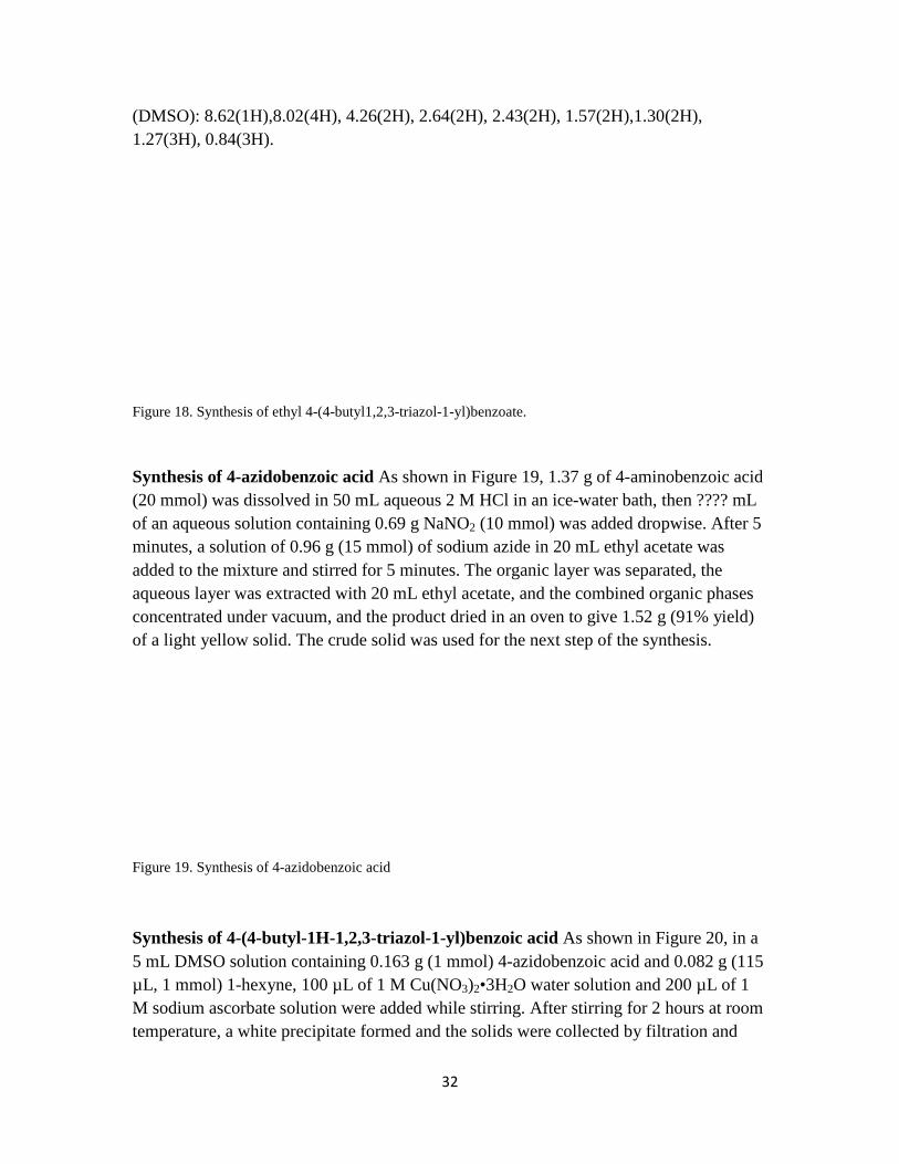
(DMSO): 8.62(1H),8.02(4H), 4.26(2H), 2.64(2H), 2.43(2H), 1.57(2H),1.30(2H), 1.27(3H), 0.84(3H).
Figure 18. Synthesis of ethyl 4-(4-butyl1,2,3-triazol-1-yl)benzoate.
Synthesis of 4-azidobenzoic acid As shown in Figure 19, 1.37 g of 4-aminobenzoic acid (20 mmol) was dissolved in 50 mL aqueous 2 M HCl in an ice-water bath, then ???? mL of an aqueous solution containing 0.69 g NaNO2 (10 mmol) was added dropwise. After 5 minutes, a solution of 0.96 g (15 mmol) of sodium azide in 20 mL ethyl acetate was added to the mixture and stirred for 5 minutes. The organic layer was separated, the aqueous layer was extracted with 20 mL ethyl acetate, and the combined organic phases concentrated under vacuum, and the product dried in an oven to give 1.52 g (91% yield) of a light yellow solid. The crude solid was used for the next step of the synthesis.
Figure 19. Synthesis of 4-azidobenzoic acid
Synthesis of 4-(4-butyl-1H-1,2,3-triazol-1-yl)benzoic acid As shown in Figure 20, in a 5 mL DMSO solution containing 0.163 g (1 mmol) 4-azidobenzoic acid and 0.082 g (115 µL, 1 mmol) 1-hexyne, 100 µL of 1 M Cu(NO3)2•3H2O water solution and 200 µL of 1 M sodium ascorbate solution were added while stirring. After stirring for 2 hours at room temperature, a white precipitate formed and the solids were collected by filtration and
33
then washed with water and dried to obtain 1.54 g of the solid product (77% yield). NMR data, ppm (nmr solvent?): 8.61(1H), 8.05(2H), 7.95(2H),2.65(2H), 1.60(2H), 1.30(2H), 0.85(3H).
Figure 20. Synthesis of 4-(4-butyl1,2,3-triazol-1-yl)benzoic acid.
Synthesis of 4-(4-phenyl-1H-1,2,3-triazol-1-yl)benzoic acid As shown in Figure 21, to a solvent of 5 mL THF and 1 mL water solution containing 0.163 g (1 mmol) 4-azidobenzoic acid and 0.102 g (110 µL, 1 mmol) phenylacetylene were added 100 µL 1 M aqueous Cu(NO3)2•3H2O and 200 µL of 1 M aqueous sodium ascorbate while stirring. A white precipitate formed after stirring in room temperature for 2 hours that collected by filtration, washed with water, and dried in an oven. 0.22 g (83.0% yield) of a white solid were recovered. NMR data, ppm (DMSO): 9.35(1H), 8.09(2H), 8.05(2H), 7.88(2H), 7.43(2H), 7.32(1H).
Figure 21. Synthesis of 4-(4-phenyl-1H-1,2,3-triazol-1-yl)benzoic acid

34
2.3 Hydrothermal synthesis of MOFs
As discussed previously, the primary objective to this research was to determine if the target ligands synthesized in the preceding section could be used to prepare MOFs with a common framework architecture identical to that of Cu MOF-3, thereby establishing a new lower-symmetry (i.e., non-cubic) family of MOFs featuring a helical chiral structure. Considering that the ligand 4-(2-ethylimidazol-1-yl)benzoic acid has the closest structure to the ligand 4-(2-methylimidazol-1-yl)benzoic acid present in Cu MOF-3, we expected the ethy-substituted ligand would be most apt to produce a MOF with identical framework structure to Cu MOF-3.
On the success of our previous work preparing MOFs, we chose to carry out hydrothermal synthesis of MOFs using the solvent system 1:1 ethanol:water (v:v).Small modifications to that solvent system made to that produced different crystalline forms of the MOF systems are described in the following experimental sections. From the knowledge of the crystalline structures of previous MOFs developed in our group (Figure 9), the octahedral coordination geometry and the orientation of the ligands in our MOFs dictate that two ligand molecules can be expected to coordinate to each metal ion (a 2:1 ratio) even when ligand to metal ratios present in solution during hydrothermal synthesis are varied from 2:1 to 4:7. In the MOF syntheses carried out in the present study, ligand to metal ion ratios of 1:1 were used. Although we previously have had success preparing MOFs both by room temperature synthesis and hydrothermal synthesis in a programmable oven at elevated temperature in sealed high-pressure microwave vials, the MOF syntheses in this study were all carried out under hydrothermal conditions on the basis that preliminary syntheses at RT utilizing the free carboxylic acids of ligands immediately produced insoluble precipitates when solutions containing the ligand and the metal salts were mixed. We have found that heating the ligand protected as the ethyl ester in the presence of metal ions salts in 1:1 EtOH/water at elevated temperature generally allows the ester to slowly hydrolize at a slow enough rate (hours to days) to produce the free carboxylic acid in low enough concentration to suppress rapid assembly of the components that leads to formation of precipitates, and allow large single crystals of MOFs to form slowly over several days.
For hydrothermal synthesis to be successful, we have found it is generally desirable to choose a solvent system and concentration range in which both the ligand and the salts of metal ions are soluble at room temperature prior to heating. Under those conditions, it is likely that initial coordination of the ligand to a metal ion occurs via the basic imidazole ring nitrogen. For example, we observed that reaction of the ligand 4-(imidazol-1-yl)benzoate as the protected ester with Cu(II) ions in 1:1 EtOH/H2O at room temperature produced a solid consisting of a discrete Cu(II) complex in which the central Cu(II) was coordinated to four of the ester ligand via the imidazole groups. We showed that

35
solubility of the initial 4:1 complex could be improved by diluting the initial solution to a lower concentration and adding reagents such as ethylene glycol. Under hydrothermal conditions, formation of solids consisting of discrete complexes is not observed due to rearrangement of the ligands to form 2:1 complexes because of more energetically favorable binding to carboxylate groups when they are unmasked during hydrolysis of the ester groups.
All hydrothermal syntheses in our laboratory generally were carried out by placing solutions of reagents sealed in glass microwave vials into a Yamato DKN 400 programmable mechanical convection oven followed by ramped heating to elevated temperature typically in the range of 70 °C to 120 °C over several days, followed by ramped cooling back to RT.
Synthesis of Cu MOF-3. As shown in Figure 22, 50 mg of ethyl 4-(2-methylimidazol-1-yl)benzoate (0.217 mmol) in 5 mL ethanol, 50 mg Cu(NO3)2•3H2O (0.207 mmol) in 5 mL water and 1 mL ethylene glycol were mixed and sealed in a microwave tube. The tube was then heated to 100 °C in an oven for one week. The tube was removed from and left standing at room temperature for weeks until dark blue crystals with needle habit formed. The crystals were only isolated by filtration from the mother solution immediately prior to analysis. These crystals were very porous and started to lose trapped cavity solvent the moment they exposed to air. The yield of the crystals was not determined but estimated below 5%.
Figure 22. Synthesis of Cu MOF-3
Synthesis of Cu MOF-3N(nonporous crystalline form of Cu MOF-3). As shown in Figure 23, 50 mg of ethyl 4-(2-methylimidazol-1-yl)benzoate (0.217 mmol) in 5 ml ethanol and 50 mg Cu(NO3)2·3H2O (0.207 mmol) in 5 ml water were mixed and sealed in a microwave tube. The tube was then heated to 100°C in an oven for one week. Dark blue crystals with column-shaped habit formed were observed in the oven after 3 days. The crystals were isolated by filtration.

36
Figure 23. . Synthesis of Cu MOF-3N. The structure of the coordination complex is shown on the right.
Synthesis of Cu MOF-4. As shown in Figure 24, 10 mg of ethyl 4-(2-ethylimidazol-1-yl)benzoate (0.041 mmol) in 2 mL ethanol and 10 mg of copper nitrate trihydrate (0.041 mmol) in 6 mL water were mixed and sealed in a 10 mL microwave vial. The vial was heated from RT to 80 °C in a programmable oven over a period of 6 hours, kept at 80 °C for 48 hours, then cooled to room temperature over 12 hours. No crystals were observed in solution upon removal of the vial from the oven. Dark blue crystals with needle habits appeared in solution after months. These crystals were kept sealed until taken for structure determination.
Figure 24. Schematic show of synthesis of Cu MOF-4
Synthesis of Cu MOF-5 . Cu MOF-5 was synthesized using the procedure described in synthesizing Cu MOF-4 as shown in figure 25. Cu MOF-5 was found in the solution

37
yielded Cu MOF-5 after 2 days exhibiting dark blue hexagonal column shape.
Figure 25. synthesis of Cu MOF-5
It is believed that it was the 2-propylimidazole mixed in the reagent 2-ethylimidazole used to synthesize the ligand stayed with ethyl 4-(2-ethyl-1H-imidazol-1-yl)benzoate. This structure was later confirmed by single crystal diffraction by multiple times that the third carbon on imidazole ring carbon 2 position was real.
Synthesis of Cd MOF-3. As shown in Figure 26, 10 mg of ethyl 4-(2-ethylimidazol-1-yl)benzoate (0.041 mmol) in 2 mL ethanol and 10 mg of cadmium nitrate tetrahydrate (0.032 mmol) in 6 mL water were mixed and sealed in a 10 mL microwave vial. Using a programmable oven, the vial was heated from room temperature to 120 °C over a period of 6 hourskept at 120 °C for 48 hours, then cooled to room temperature over a period of 12 hours. Transparent, colorless, crystals with rectangular-shaped habits were present in solution when the vial was removed from the oven. These vials would only open prior to single crystal X-ray diffraction structure determination for the reason these crystals would eventually breakdown to powder exposing to air. Crystals were filtered and dried in 100 °C oven prior to sorption study.
Figure 26. Synthesis of Cd MOF-3
Unfortunately, our attempts to construct MOFs utilizing 1,2,3-triazole analogs have not yielded any MOF structure. In our effort to build MOF using triazole analogs we have

38
synthesized, it was observed these triazole compounds tend to interact with itself, may due to its aromatic nature that forms efficient stacking of its own. The usual phenomenon (such as solution adopted a darker color once metal and ligands were mixed, for example the mixing of copper and 4-imidazolylbenzoic acid) of metal coordinating was not observed.
Determination of the crystal structures of MOFs. The crystal structures of MOFs were solved to determine the molecular structures of the metal complexes and conformations of the ligands, the framework architectures and connectivity, and whenever possible, to identify the presence of solvents present as guests within the MOF structures.. The following experimental procedures were used to collect the X-ray diffraction data and solve the crystal structure. Batches of crystals were removed from solution and immediately placed under paratone oil to prevent guest solvent from leaving the crystals. A single crystal of MOF covered in paratone oil was placed on a 100µ MiTeGen polyimide micromount that was then mounted on a Bruker-AXS Kappa APEX CCD diffractometer equipped with an LT-II low temperature device. The mounted crystal was cooled to 100K under a stream of nitrogen gas, causing the paratone oil to solidify and prevent guest solvent from escaping from the crystals. Diffraction data were collected at 100(2) diffractometer equipped with an LT-II low temperature device. Diffraction data were collected at 100(2) K using graphite monochromated Mo-Kα radiation (λ=0.71073Å) using the omega scan technique. Empirical absorption corrections were applied using the SADABS program. The unit cell and space group were determined using the SAINT+ program. The structures were solved by direct method and refined by full matrix least-squares using the SHELXTL program. Refinements were based on F2 using all reflections. All non-hydrogen atoms were refined anisotropically. Hydrogen atoms on carbon atoms were all located in the difference maps and subsequently placed at idealized positions and given isotropic U values 1.2 times that of the carbon atom to which they were bonded. Mercury 1.4.2 software was used to examine the molecular structure in the solved crystal structure. The crystallographic data for Cu MOF-3N, Cu MOF-4, Cu MOF-5, and Cd MOF-3 are shown in Table 2.

39
Table 2. Crystallographic data of Cu MOF-3N, 4, 5 and Cd MOF-3
Name Cu MOF-3N Cu MOF-4 Cu MOF-5 Cd MOF-3 Formula C22H18CuN4O4 C24H22CuN4O4 C26H26CuN4O4 C22H18CdN4O4 Formula weight 465.96 494.01 522.06 514.82 Crystal system orthorhombic hexagonal monoclinic monoclinic Space group Pbcn P6(5) P 21/n Cc Crystal color Dark blue Dark blue Dark blue Colorless a (Å) 13.1577(3) 17.3526(11) 8.7782(2) 13.0212(3) b(Å) 10.1096(2) 17.3526(11) 17.7685(3) 27.2010(8) c (Å) 16.5781(4) 24.6393(35) 10.7584(5) 8.8586(2) α (°) 90 90 90 90 β (°) 90 90 110.817 129.626(1) γ (°) 90 120 90 10 Cell volume (Å3) 2205.2 6425.22 1568.5 2416.67 Z 4 11 3 4 No. Reflns 2761 2143 3898 R 0.0295 0.1727 0.0827 0.0286 wR2 0.0788 0.1674 0.0638
All the hydrothermal synthesis have yielded the deprotected carboxylate in the final MOF structure. All the structure exhibit 4 ligands attached to the central metal ion, which is copper or cadmium. As described at previous section, the 3 binding patterns (figure 27 left, middle and right) continue to show up in these structures.
Figure 27 far left: square planer, middle left: tetrahedral distribution, middle right: square planer(trans), far right: square planer (cis)
Analysis of the crystal structure of the Cu MOF-3N (metal coordination structure as shown in figure 28) revealed that each copper ion binds to two imidazole nitrogen monodentately and two carboxylate monodentately (as illustrated in figure 27 second right structure), which has the same coordination number as Cu MOF-3. The coordination difference between Cu MOF-3 and Cu MOF-3N resulting the complete structure change was that the methyl groups of the imidazole rings around the copper ion exhibit trans-distribution around Cu MOF-3N while Cu MOF-3 exhibit cis-distribution. The cis-distribution of ligands of Cu MOF-3 created a curved chain structure later resulting a

40
continued helical backbone chain demonstrating chirality. The trans-distribution of methyl ligands form a perfect square planar, forming a two dimensional network with square channels (the 2-d framework is shown in figure 29. Left shows a 2-D network formed by this square planar. Right is the structure view of Cu MOF-3N constructed by several interpenetrating 2-D networks). It was observed this structure was not constructed only by one fold of these networks. We observed several fold of 2-D networks weaving into each other affording this coordination polymer non-porous.
Figure 28 The spatial view of the Cu-ligand2 complex trans
Figure 29. The 2D network of one square planner layer (left) and 2D network with the other network penetrating (right).
This structure analysis is later confirmed by weight loss experiment by TGA. TGA heating showed a weight loss of 3% (shown in figure 31). This loss amount is comparable to previous found non-porous MOFs (weight loss of 2%), which is consider non-porous. TGA experiment result is consistent with our structure analysis of Cu MOF-3N.

41
Figure 30 Structure of Cu MOF-3N of one unit cell
Figure 31 Cu MOF-3N loses approximate 3% of its mass up to 200 °C, demonstrating non-porous behavior
By single crystal X-ray diffraction structure determination, we observed that Cu MOF-4 successfully adopted the structure of Cu MOF-3. The two MOFs have almost identical crystallographic data (as crystallographic parameters of Cu MOF-3 and Cu MOF 4 are listed in table 3). Cu MOF-4 adopted the cis planer square distribution as illustrated at figure 27 first right structure.
020406080
100120
0 100 200 300 400 500
Wei
ght
loss
%
temperature °C

42
Table 3 Crystallographic data of Cu MOF-3 and Cu MOF-4
Name Cu MOF-3 Cu MOF-4 Formula C22H18CuN4O4 C24H22CuN4O4 Formula weight 465.96 494.01 Crystal system hexagonal Hexagonal Space group P6(1) P6(5) Crystal color Dark blue Dark blue a (Å) 16.2421(2) 17.3526(11) b(Å) 16.2421(2) 17.3526(11) c (Å) 25.6313(5) 24.6393(35) α (°) 90 90 β (°) 90 90 γ (°) 120 120 Cell volume 5855.79 6425.22 Z 21 11 No. Reflns 5948 2143 R 0.1171 0.1727
Due to the dangling of the ethyl group on imidazole ring, the second carbon position is ambiguous. This results the higher R1 value of the Cu MOF-4 structure. The similar crystal cell parameters provided the original hint of the Cu MOF-4 adopting Cu MOF-3 framework structure. The crystal structure of Cu MOF-4 is shown in figure 32.
Cu MOF-4 is a porous MOF that has exceptionally wide helical channels within it. Look closer at the imidazole ring and we have found out that the uncertainty of the 2-carbon position of the ethyl group grant this carbon invisible from the structure, suggesting the flexibility of moving space it can be found.
Cu MOF-4 loses a significant amount of its weight as it gets heated. Figure 3 shows the thermal behavior as it is being heated. Cu MOF-4 loses a comparable amount (30%) of ethanol and water as to Cu MOF-3 (30%). Please be noted that it was observed to lose guest molecules once it was pulled out of solution it was form. It can be observed to gradually lose its transparency in air. It was observed TGA instrument took about 5 min to record initial mass, while Cu MOF-4 had started to loss its solvent.

43
Figure 32. Above: Crystal structure from the C axis of Cu MOF-4. Structure failed to show 50% of the second carbon on ethyl group on the imidazole ring due to the spatial uncertainty of the floppy ethyl group. Below: TGA curve of Cu MOF-4 as it gets heated at 10 °C per minite to 350 °C. At 100 °C it exhibits a loss of 30% of its mass; it lost a total of 35% before it decomposed.
0
20
40
60
80
100
120
0 50 100 150 200 250 300 350 400
wei
ght l
oss
%
temperature °C

44
We also find out another hexagonal rod-shaped dark blue crystal Cu MOF 5 in the same solution that Cu MOF-4 was yielded. Solving the structure, we find out it is a new structure adopting a distribution similar to Cu MOF-1 and Cu MOF-2, also as the scheme shown in figure 27 (far left one). It forms a square planer distribution, assembling into a 2-D structure (as shown in figure 33). Figure 33 above shows the view of one layer of the 2-D network, with solvents trapped in its network cavities. Figure 33 below is the view from crystal cell b axis, showing 4 layers of those 2-D networks. The interactions between different layers of 2-D networks are mainly van der waals interaction, with the last methyl group pointing to the benzene ring of neighboring network.
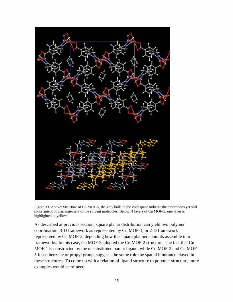
45
Figure 33. Above: Structure of Cu MOF-5, the grey balls in the void space indicate the amorphous yet still some anisotropy arrangement of the solvent molecules. Below: 4 layers of Cu MOF-5, one layer is highlighted in yellow
As described at previous section, square planar distribution can yield two polymer coordination: 3-D framework as represented by Cu MOF-1, or 2-D framework represented by Cu MOF-2, depending how the square planner subunits assemble into frameworks. In this case, Cu MOF-5 adopted the Cu MOF-2 structure. The fact that Cu MOF-1 is constructed by the unsubstituted parent ligand, while Cu MOF-2 and Cu MOF-5 fused benzene or propyl group, suggests the some role the spatial hindrance played in these structures. To come up with a relation of ligand structure to polymer structure, more examples would be of need.

46
Of all the cadmium MOFs have developed in our group, cadmium metal complex always form tetrahedral complex around the metal ion (as illustrated in figure 27 middle left). As the original design, these cadmium MOFs should all exhibit adamantine (diamond) cage structure and they do (figure 34 shows an adamantine view of Cd MOF-2). If no interpenetration would have occurred, this structure would be extremely porous. As the nature has the tendency to compromise for tighter packing and maximize favorable contact, penetration would occur when the channels are big enough to accommodate another fold of the same framework. All the cadmium structures exhibit interpenetration, which have decreased their pore volume. For the case of Cd MOF-1 and Cd MOF-2, they exhibit smaller channels then designed while remaining some degree of porosity.
Figure 34 Adamentine view of a single fold of framework of Cd MOF-2, which hides the other frameworks interpenetrate with this frame.

47
Figure 35 The 4-fold interpenetration view of Cd MOF-1, different colors indicate one fold of framework.
Cd MOF-3 adopted a saturated octahedral coordination, with two carboxylate and two imidazole bindings exhibiting a tetrahedral districbution. This tetrahedral coordination further developed into 3-D network which is similar to diamond structure. Since this diamond cage is so hollow, interpenetration occurs, which is not surprising. Our previous example with Cd MOF-1, 4 fold interpenetration still yielded significant porosity. Cd MOF-3 has a degree of interpenetration of 5 fold (as shown in figure 37, different color representing a non-covalent binding independent network), which is one fold more than Cd MOF-1. The absolute structure exhibits a close efficient packing of 5-fold of diamond network interpenetration packing, resulting no channel big enough to accommodate guest solvent molecules.
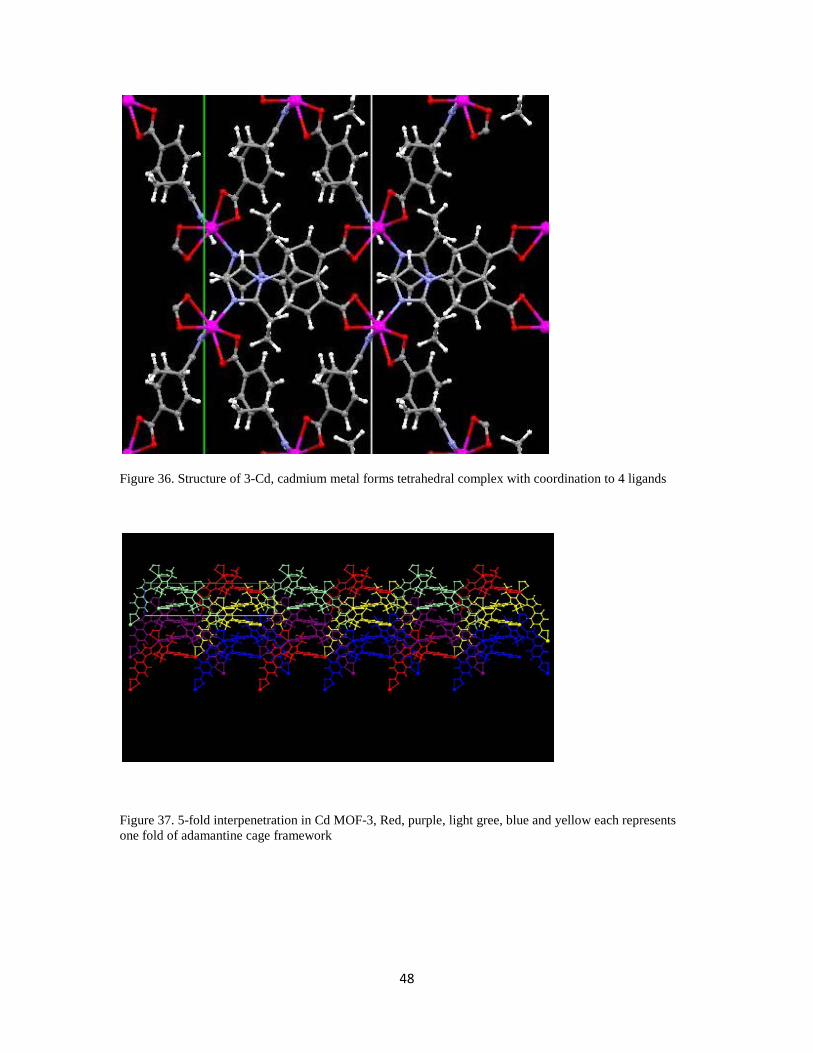
48
Figure 36. Structure of 3-Cd, cadmium metal forms tetrahedral complex with coordination to 4 ligands
Figure 37. 5-fold interpenetration in Cd MOF-3, Red, purple, light gree, blue and yellow each represents one fold of adamantine cage framework

49
2.4 Conclusion
We have successfully synthesized more ligands based on 4-(imidazolyl)benzoic acid and 4-(1,2,3-triazolyl)benzoic acid structures. Synthesizing 4-(imidazolyl)benzoic acid substituent with longer or more sterically demanding alkyl or aryl group has shown increased difficulty. Our effort to circumvent this difficulty as synthesizing the 1,2,3-triazole analogs afforded 3 ligands to work with, but unfortunately the effort to construct MOFs utilizing this family of ligands failed to yield any MOF.
We have successfully synthesized 4 new MOFs utilizing 4-(imidazolyl) benzoic acid ligands: Cu MOF-3N, Cu MOF-4, Cu MOF-5 and Cd MOF-3. Cu MOF-5 and Cd MOF-3 exhibit saturated octahedral coordination, showing square planer and tetrahedral distribution as illustrated in our proposal.
Our hypothesis that longer alkyl group should preserve Cu MOF-3 architecture is proven by successful synthesis of Cu MOF-4. Cu MOF-4 loses 35% of its mass up to a temperature of 250°C.
The finding of Cu MOF-3N shows our class of MOF constructed by 4-(imidazolyl)benzoic acid exhibit polymorphs. The trans coordination of the ligands resulted no porosity.
The above findings also showed changing the substituents on parent ligands gave MOF different architectures.

50
3. Sorption Studies of Polyaromatic Hydrocarbons and Pharmaceuticals by MOFs
3.1 Introduction
Over past decade nearly 2200 papers investigating MOFs have appeared in the scientific literature, the vast majority of which have focused on developing the synthetic methodology necessary to synthesize MOFs. A large library of MOFs have been prepared and the structures reported during that time, greatly expanding the repertoire of available architectures beyond the cubic framework first reported for MOF-5 by Yaghi.29 More recently, the focus of research on MOFs increasingly has shifted away from synthesis and development of new structures toward investigating the porous behavior of MOFs and their applications as functional host materials. One important area that is beginning to be explored is sorption of molecular guests by MOFs to examine whether MOFs exhibit selectivity toward sorption of certain types of organic compounds and determine the origin of that selectivity.
Sorption. Sorption of molecular guests is the energetically favorable process whereby a porous material takes in molecules by absorbing/adsorbing them within/onto channels during diffusion. The material accommodates the guests either as species on the surface of or within the void space of pores. By filling the accessible free internal surface of pores, the surface free energy of the system (host and guest) is lowered.59 As such, the process of molecular sorption into a porous host is spontaneous.
MOFs as hosts for molecular sorption. The most important structural feature of MOFs is that they have channels with void volumes and surfaces areas large enough to accommodate a wide variety of guest molecules. The ability to control the dimensions of channels and adjust their surface properties through the appropriate choice of the organic components has the potential to allow the selectivity of MOFs toward sorption of guests to be controlled both on the basis of size and functionality of guests. Studies aimed at tailoring interaction between the internal surfaces of MOF frameworks and guests are now emerging that demonstrate the utility of MOFs for controlling a wide range of processes involving molecular sorption such as heterogeneous catalysis, asymmetric synthesis, storage of energy, and molecular separation to name just a few.6 The ability of MOFs to promote sorption of guest molecules within channels via favorable intermolecular interactions (e.g., van der Waals, hydrophobic, dipolar, hydrogen bonding, etc.) therefore is central to the functionality of MOFs.
One area where MOFs are proving invaluable as sorbent materials is for storage of energy. For example, recent research has shown that MOFs are able to sorb high densities

51
of hydrogen upon exposure to that gas under moderate pressure.60 One diffraction study in which the structure of a MOF was examined iteratively while introducing hydrogen at increasingly higher pressures revealed that hydrogen selectively accumulated first near metal centers and the surfaces of aromatic rings, followed by nonspecific loading into the remaining void spaces.61-63 That work demonstrated that loading of nonpolar hydrogen initially is driven via favorable van der Waals interactions between molecules of hydrogen and the surface of the hydrophobic aromatic components in the backbone of the framework. Although MOFs are known to sorb a range of nonpolar and polar organic guests small enough to diffuse into the MOF channels, the mechanistic and energetic details as well as structure-function relationships responsible for molecular sorption are not yet fully understood.
In this chapter, we investigated the sorption behavior of two MOF systems exhibiting two different pore dimensions toward nonpolar, aromatic guests consisting of a small library of polyaromatic hydrocarbons, and also toward a small library of polar, aromatic guests comprised of pharmaceutical drugs. The immediate aims of this research were to determine whether those MOFs were capable of sorbing those guests, whether they showed selectivity toward sorbing higher concentrations of nonpolar vs. polar guests, and whether increasing the size of guests to more closely match the pore dimensions lead to greater selectivity. This study is part our initial efforts to quantify the selectivity of MOF toward hydrophobic and hydrophilic guests. The results of this work will be used to identify families of MOFs with optimal sorption behavior for the development of sorbent materials for environmental remediation and drug delivery.
3.2 Strategy
Characterization of the sorption behavior of MOFs toward small guests such as hydrogen and other small organic compounds that are gases typically has been evaluated via gas sorption experiments under low pressures to generate BET or Langmuir gas sorption isotherms.64 In addition to providing data on loading capacities toward a given gas, those techniques provide structural information about the internal void volumes and surfaces areas of the MOF hosts. Given that the guest compounds examined in our study all are solids at room temperature, sorption of guests was examined in solution. Loading of guests in MOFs was followed by placing MOFs in ethanolic solutions of guest in varying concentration and then monitoring uptake of the guest from the solutions by liquid chromatography. Selectivity of a given MOF for sorbing different guests was evaluated by comparing the loading capacities of each guest from solutions at the same initial concentration and also by carrying out competition studies from solutions containing mixtures of the different guests.

52
Choice of MOFs. As a general requirement, in order for sorption of guest molecules to occur, MOFs must have pore channels with dimension large enough to allow guest molecules to diffusion of guests. Therefore, we chose two MOF systems to examine that included Cd MOF-2 developed in our group and Yaghi’s MOF-5. Cd MOF-2, which features 4 Å x 10 Å channel openings with a solvent accessible surface area of 617 m2/g and void volume of 3.0 × 10⁻⁸m3/g, was selected because it represents a low-symmetry MOF architecture with a small pore diameter just wide enough to admit aromatic rings. Guests with dimensions that closely match those of pores in the host generally can be expected to show higher binding affinity when compared to smaller guests because a snug fit maximizes energetically favorable intermolecular contacts. MOF-5, which has larger 13 Å by 13 Å channel openings that result in a solvent accessible surface area of 3774 m2/g and void volume of 8.3 × 10⁻⁸m3/g,17,29 was selected because it represents a high-symmetry MOF architecture (i.e., cubic) with pore diameter much larger than the dimensions of the guests in this study.
Comparison of the structures of Yaghi’s MOF-5 and our Cd MOF-2 shown in Figure 38 reveals several structural features that both MOFs share in common. The frameworks consist of hydrophilic metal centers (highlighted in yellow) generated by coordinated oxygen atoms (and nitrogen atoms in Cd MOF-2) that provide sites at which polar guests potentially can interact by forming hydrogen bonds. The frameworks in both MOFs feature hydrophobic walls (highlighted in blue) consisting of the aromatic backbones of the linking ligands. Analysis of space-filling models of those structures revealed that the metal centers are buried within the walls and that the aromatic rings in the framework provide most of the exposed surface. Therefore, we hypothesized that those MOFs would exhibit higher affinity for sorption of hydrophobic guests compared to hydrophilic guests. We also expected that larger guests with sizes that more closely match the channel dimensions of the MOF would show greater binding affinity.

53
Figure 38. Cap and stick (top) and space-filling (bottom) views of crystal structures and channels of MOF-5 and Cd MOF-2.
Choice of guest molecules. To examine the effects of size and polarity on sorption, we chose small samples of guests consisting of nonpolar, hydrophobic polyaromatic hydrocarbons and polar hydrophilic pharmaceutical drugs that vary in size as test systems.
Polyaromatic hydrocarbons (PAHs) are hydrophobic hydrocarbons that consist of fused aromatic rings. Three PAHs were chosen for this study—naphthalene, phenanthrene and pyrene—because i) they are hydrophobic, ii) they have dimensions smaller or comparable to that of the MOF channels, and (iii) they increase incrementally in length and width, making them a suitable set of guests to investigate surface interactions with the walls of the channels. Another reason for investigating the sorption of PAHs was to test the potential of using MOFs in environmental remediation. PAHs are widespread carcinogenic pollutants that are present in processed fossil fuels, asphalt and natural water sources.65,66 The structures and relevant physical data for naphthalene, phenanthrene and pyrene are shown in Table 4.

54
Table 4. Chemical structures, formulas, molecular weights, and molecular dimensions for naphthalene, phenanthrene, and pyrene.
Naphthalene phenanthrene Pyrene C10H8 C14H10 C16H10 Mw=128.2 Mw=178.2 Mw=202.3 dimensions dimensions dimensions 9Å×7Å×3.5Å 11.5Å×8Å×3.5Å 11.5Å×9Å×3.5Å
In addition to hydrophobic guests, we wanted to examine sorption of polar guests with MOF-5 because MOF-5 contains electronegative oxygen atoms exposed around the coordination centers that might participate in hydrogen binding with guests that contain hydrogen-bonding donor groups such as alcohols and carboxylic acid OH groups. To investigate whether hydrogen binding occurs with MOF-5 that promotes higher loading or increased selectivity within the MOF channels, we chose to test 2 polar guests—2-naphthol and ibuprofen. The structures and physical data for 2-naphthol and ibuprofen are given in Table 5.Those polar guests were selected i) because they feature acidic OH groups that are capable of participating in hydrogen bonding, and ii) because they are similar in size to the hydrophobic guests (e.g., naphthalene) and should fit within the MOFs. We were particularly interested in the sorption behavior of the pharmaceuticals ibuprofen assess whether MOFs might serve as container materials for controlled delivery of drugs.
Table 5. Chemical structures, formulas, molecular weights, and molecular dimensions for 2-napthol and ibuprofen.
Ibuprofen 2-napthol M.W.= M.W.= 144.17 Dimensions dimensions 10.8Å×4.8Å×3.5Å 10Å×7Å×3.5Å

55
3.3 Sorption of guest molecules
Synthesis of MOF-5. MOF-5 is synthesized according to protocol established by L. Huang et al.67 In a 40 mL DMF solution containing 1.21 g Zn(NO3)2·6H2O (4 mmol) and 0.34 g H2BDC (terephthalic acid, 2mmol), 1.6 g triethylamine (16 mmol) was added during vigilant stirring in room temperature. After 30 minutes a white precipitate that appeared was filtered and washed thoroughly by DMF 3 times, oven dried and activated at the temperature of 170 °C for one week. The solids were characterized via powder X-ray diffraction pattern prior to use and that PXRD trace compared to the published data to confirm that MOF-5 was present. Cd MOF-2 was synthesized according to the procedure developed previously in our group. A solution containing 3 (10 mg, 0.04 mmol) and Cd(NO3)2•6 H2O (5 mg, 0.02mmol) was combined with 6 mL of 2:1 EtOH:H2O and placed in a 10 mL microwave glass vial and sealed. The vial was heated for 6 hours to 120 °C and kept at that temperature for 48 hours then cooled to 25 °C for 12 hours, yielding clear long rectangular prism crystals of Cd MOF-2. Crystals of Cd MOF-2 were present when the vial was removed from the oven. Cd MOF-2 was filtered prior to use and activated by heating the MOF at 120°C for 2 days.
Guest molecules. Naphthalene, phenanthrene, 2-napthol and ibuprofen were purchased from Sigma Aldrich as ACS degree and used without further purification. Pyrene was purified by column chromatography on a silica gel column using hexane as eluting solvent.
Solvent system and sampling method. Solutions of the guests were prepared in ethanol over a range of concentrations. Ethanol was used because all guests exhibited solubility in that solvent.The concentration range for naphthalene and phenanthrene was 2.0 – 20.0 mM, while the concentration range for the pyrene was 0.2 – 6.0 mM. Higher concentrations of pyrene were not used to avoid aggregate formation and problems with UV detection associated with the high molar absorptivity of pyrene. The concentrations of solutions were measured by liquid chromatography using an Agilent 1100 LC-MS equipped with a C-18 column and UV-Vis detector. Calibration curves were generated by plotting the areas of peak against the concentrations of guest in ethanol across the range of concentration. Solutions of samples for sorption were prepared in 2.0 mL Agilent LC vials with a rubber septum caps. Activated MOF powder (50 mg) was added to the LC vials along with 1.00 mL of guest solution at a given concentration. The vial was then immediately placed on the LC sequencing tray along with vials of same guest solutions at different concentration, all containing 50 mg of the same MOF. The LC instrument then injected 5.0 µL aliquots from each vial into the column at different times to measure the concentrations of guest remaining in solution.

56
Sorption behavior. Samples with various ratios of guest to MOF examined to determine the final equilibrium concentrations of sorbate remaining in solution. In order to compare different guests, the unit of mmol/L (mM) and mmol/50 mg for the liquid and solid phases were used for the guests in this study. The amount of guest sorbed at the time t and equilibrium were calculated using the equations
𝑞𝑡 = (𝐶0 − 𝐶𝑡) × 𝑉
𝑞𝑒 = (𝐶0 − 𝐶𝑒) × 𝑉
where qe and qt are the guest concentrations in the MOF at equilibrium and time t , respectively; C0, Ct, and Ce are the initial concentration, the liquid-phase concentration at time t , and the equilibrium concentration of guest, respectively; V is the volume of the aqueous solution and equal to 0.001 L.
Sorption equilibria For investigation of the sorption of guests on MOFs in this study, the empirical Langmuir isotherms, which correspond to homogeneous MOF surfaces, was used to correlate the experimental data as equation 165,
Equation 1
𝑞𝑒 =𝑄𝐿𝐾𝐿𝐶𝑒
1 + 𝑄𝐿𝐾𝐿
QL and KL are the Langmuir isotherm constants, representing the monolayer adsorption capacity and equilibrium constant, respectively. The constants in the models can be obtained by linearizing the above equations as equation 2,65
Equation 2
1𝑞𝑒
=1
𝑄𝐿𝐾𝐿𝐶𝑒+
1𝑄𝐿
According to the lower limit of the Langmuir isotherm (i.e., KLCe<<1), the Langmuir isotherm can be reduced to a linear isotherm as equation 3,65
Equation 3
𝑞𝑒 = 𝐾𝑑𝐶𝑒
Where Kd is the equilibrium distribution coefficient describing the distribution of liquid in the MOF.

57
Sorption of PAHs in MOF-5 The Langmuir isotherm of naphthalene, phenanthrene and pyrene in MOF-5 is shown on Figure 39 and Langmuir and linear constant fitting data in Tables 6 and 7.
Figure 39. Langmuir isotherm of naphthalene, phenanthrene and pyrene in MOF-5 (low concentration).
The higher sorption of phenanthrene over naphthalene further indicates that the guests are interacting with the walls, the larger guests showing higher affinity that leads to enhanced sorption. Only two data points were determined for pyrene due to aggregation of pyrene in solution and problems with accurate UV detection at higher concentration the data is consistent with higher sorption of larger guest observed for phenanthrene compared to naphthalene.
Table 6. Langmuir model constants for the sorption of three PAHs by MOF-5 and the R2 value (calculated by plotting equation 2).
Naphthalene Phenanthrene Pyrene KL 1.30×10⁻² 7.55×10⁻³ 2.52×10⁻¹ QL 4.00×10⁻³ 2.14×10⁻² 1.81×10⁻³ R2 0.970 0.993 NA
Table 7. Linear model constants for the sorption of three PAHs by MOF-5 and the R2 value.
Naphthalene Phenanthrene Pyrene Kd 4.10×10⁻⁵ 1.52×10⁻⁴ 2.61×10⁻⁴ R2 0.885 0.997 0.772
0
0.2
0.4
0.6
0.8
1
1.2
0 0.2 0.4 0.6 0.8 1 1.2
Sorb
ed a
mou
nt m
mol
/50m
g so
bent
equilibrium concentration (mM)
Naphthalene
Phenanthrene
Pyrene

58
Sorption of PAHs in Cd MOF-2 A similar set of sorption experiments was performed to examine sorption of the 3 PAHs by Cd MOF-2 (Figure 40). The Langmuir analysis was performed on the sorption data. The Langmuir isotherms obtained from the equilibrium number of moles sorbed and the calculated equilibrium concentrations for the three PAHs in Cd MOF-2 were in table 8.
Figure 40. Sorption isotherm of 3 PAHs in Cd MOF-2 (low concentration)
Table 8. Langmuir model constants for the sorption of three PAHs by Cd MOF-2 and the R2 value.
Naphthalene Phenanthrene Pyrene KL -1.16×10⁻¹ -1.57×10⁻¹ -3.55×10⁻¹ QL -8.73×10⁻⁴ -4.63×10⁻⁴ -3.20×10⁻³ R2 0.72 0.90 0.88
Although the isotherms for sorption of naphthalene, phenanthrene, and pyrene by Cd MOF-2 behave in a different manner mathematically compared to those obtained for MOF-5—that is, the Langmuir constants are negative—the general trend is similar to the results obtained for MOF-5. As predicted, sorption of the PAH guest at the same initial concentration is consistently higher in Cd MOF-2 compared to MOF-5. The higher relative affinity of PAH guests for Cd MOF-2 is consistent with our hypothesis that the smaller 10 Å × 4 Å channels in Cd MOF-2 (vs. 13 Å × 13 Å channels in MOF-5) provide a tighter fit that enhances sorption of the PAH guest via hydrophobic van der Waals interactions with the aromatic ligands present on the walls of the channels.
0
0.002
0.004
0.006
0.008
0.01
0.012
0.014
0.016
0 2 4 6 8
Am
ount
sor
bed
in 5
0mg
sorb
ent (
mm
ol)
Equilibria concentration (mM)
naphthalene
phenanthrene
pyrene

59
PAH competition in MOF-5 Since the results present above indicates phenanthrene exhibits larger affinity to MOF-5 than naphthalene, a competitive sorption experiments was carried out to further confirm our hypothesis: MOF-5 would selectively sorb phenanthrene for it exhibits larger surface area. Three solutions containing equimolar of naphthalene and phenanthrene was prepared and conducted the sorption experiments at the same manner as described above. Concentrations were determined after 48hrs by HPLC. Results are shown in the following Figure 41.
Figure 41. Comparison of the number of moles of naphthalene (red) and phenanthrene (blue) sorbed by MOF-5. The numbers over column indicates folds of amount of selectivity.
As the results from the linear fit of sorption isotherm of PAHs in MOF-5, the ratio of Kd of phenanthrene to naphthalene was 1.52×10⁻⁴/4.10×10-5=3.8, the competition results show MOF-5 preferentially sorbs phenanthrene over naphthalene by an average factor of 8.2±0.3 at the concentration tested.
Polar guest in MOF-5 While MOF-5 has Zinc-oxide clusters that in principle should enable hydrogen bonding with the guest to occur, the data in Figure 42 for 2-napthol shows that guest is not sorbed by MOF-5. Though 2-napthol is similar in size to naphthalene, no sorption was observed throughout the range of concentration within the experimental error. That result was unexpected and quite surprising considering that even
0
0.0002
0.0004
0.0006
0.0008
0.001
0.0012
0.0014
2mM 3mM 5mM
Mol
es s
orbe
d (m
mol
)
Co (mM)
naphthalene
phenanthrene
8.3
8.5
7.9

60
if 2-naphthol does not participate in hydrogen bonding within MOF-5, it is reasonable that sorption should still occur due to hydrophobic interactions between the naphthyl rings and the aromatic components of the MOF framework. That suggest hydrogen bonding is not a driving force would concentrate the guest molecules in the MOF solid pores. To the opposite, the fact that these pores tend to select naphthalene over naphthol, suggests these pores are very hydrophobic.
Figure 42. Sorption isotherm for 2-naphthol in MOF-5.
As shown in Figure 43 and Table 9, ibuprofen shows a fair amount of sorption in MOF-5. Because the 3 PAHs and ibuprofen adsorptions are done at different concentration ranges (due to percentage error of naphthalene and pyrene cannot make high concentration solution), previous PAHs are measured below 20mM. In order to compare, the calculated Langmuir constant QL was used. It offers a tool to compare different sorbing amount at different concentration. According to QL calculation, maximum amount ibuprofen adsorbed by MOF-5 is 1.88×10⁻³ mmol/50mg sorbent, lower than naphthalene (4.00×10⁻³ mmol/50mg sorbent) and phenanthrene (2.14×10⁻² mmol/50mg sorbent). The amount of sorption of ibuprofen is closer to that of naphthalene, which is comparable to the size for ibuprofen has a size of naphthalene.
0.8
0.85
0.9
0.95
1
1.05
1.1
0 50 100 150 200
C/C 0
time (minute)
2.0mM naphthol
2.1mM naphthalene

61
Figure 43. Langmuir isotherm for sorption of ibuprofen by MOF-5
Table 9 Langmuir model constants for the sorption of ibuprofen by MOF-5 and the R2 value
Ibuprofen KL 8.24 QL 1.88×10⁻³ R2 0.996
Though ibuprofen and 2-napthol both have decreased sorption amount, ibuprofen exhibit a sorption amount lower than naphthalene while 2-napthol exhibit no sorption considering systematic error. One answer may lies in the fact ibuprofen is very hydrophobic pharmaceutical compared to other NSAIDs (Non-steroidal anti-inflammatory drug) and has very low water solubility.
Previous PAHs isotherm experiments are conducted at lower concentration (<20mM). We would like to see if the isotherm fitting parameters are still the same at the higher concentration. The isotherm of phenanthrene at higher concentration (to the concentration phenanthrene is almost saturated in ethanol) and parameters are shown in figure 44 and table 10.
00.0020.0040.0060.008
0.010.0120.0140.016
0 20 40 60 80 100
sorb
ed a
mou
nt (m
mol
e)
equilibrium concentration (mM)

62
Figure 44 Langmuir isotherm for sorption of phenanthrene by MOF-5 (higher concentration)
Table 10 Langmuir model constants for the sorption of phenanthrene (obtained at higher concentration) by MOF-5 and the R2 value
Phenanthrene (high conc.) Phenanthrene (low conc.) KL 1.32×10⁻² 7.55×10⁻³ QL 3.12×10⁻² 2.14×10⁻² R2 0.984 0.993
From the result of phenanthrene (higher concentration) isotherm, the calculated maximum sorption remains the same, though there is a change of the adsorption constant KL. The possible reason may be that phenanthrene is sorbed into MOF-5 pores in a multilayer manner at higher concentration.
The calculated maximum sorptions by low concentration experiment data and high concentration experiment data of phenanthrene are consistent, demonstrating that the maximum sorption calculated by lower concentration experiment is reliable. That enables us to compare maximum sorption of 3 PAHs and ibuprofen (because 2-napthol exhibits no sorption) through different experiments.
The size of 5 molecules are napthol≈ibuprofen≈napthalene<phenanthrene<pyrene, while the maximum sorption of these molecules are napthol (close to 0) < ibuprofen <naphthalene <phenanthrene (pyrene is not included for too few data points but the isotherm suggests a trend of higher sorption as shown in figure 39 & 40).
0
0.005
0.01
0.015
0.02
0.025
0 20 40 60 80 100 120 140
amou
nt s
orbe
d
phenanthrene concentration (mM)

63
3.4 Conclusion
The sorption of naphthalene, phenanthrene and pyrene showed increased size resulted increased sorption with both porous solids MOF-5 and Cd MOF-2. Also, sorption of the PAH guest at the same initial concentration is consistently higher in Cd MOF-2 compared to MOF-5. The higher relative affinity of PAH guests for Cd MOF-2 is consistent with our hypothesis that the smaller 10 Å × 4 Å channels in Cd MOF-2 (vs. 13 Å × 13 Å channels in MOF-5) provide a tighter fit that enhances sorption of the PAH guest via hydrophobic van der Waals interactions with the aromatic ligands present on the walls of the channels. The competition of naphthalene and phenanthrene further confirmed this hypothesis.
The MOF-5 sorption results from non-polar polyaromatic hydrocarbons and polar naphthol and ibuprofen showed polar molecules showed lower or no affinity to MOF-5. The case of naphthol suggests the existence of hydroxyl group does not increase the affinity, instead, hydroxyl group decreased the guest molecule affinity to MOF-5 dramatically.

64
4. Surface-Induced Nucleation of a New Polymorph of Indomethacin on MOF-5
4.1. Introduction
Polymorphism is a frequently observed phenomenon in the solid state that arises when crystallization of a compound produces different crystalline forms—called polymorphs—in which the molecules adopt different packing arrangements. The resulting polymorphs often can be distinguished visually on the basis of different crystal habits (morphology or shap) and experimentally because polymorphs generally exhibit different physical properties (e.g., melting point, solubility, color, etc.).68 The incidence of polymorphism is of particular important in the development of drugs because polymorphs of drugs are regarded as unique substances in courts of law. Despite substantial effort by the scientific community to develop experimental methods to identify all polymorphs of drugs as well as computational methods to predict the structures of polymorphs, the incidence of new polymorphs remains a persistent problem. Recently, studies involving the use of surface templates to control polymorphism have shown that surfaces play a critical role in influencing molecular aggregation leading to nucleation and subsequent growth of polymorphs.69 For example, self-assembled monolayers70,71 and polymers72 have been used successfully as surface templates to crystallize polymorphs selectively based on strong intermolecular interactions between functional groups exposed on the surface and molecules of solute in solution.
In this Chapter, we report a new polymorph (an ethanol solvate) of the pharmaceutical drug indomethacin (IMC) for the first time that resulted from templated growth on the surface of MOF-5. Although discovery of that polymorph was serendipitous, to our knowledge it represents the first incidence (1) where a MOF has served as a surface template leading to nucleation of a polymorph, and (2) where the resulting polymorph cannot be crystallized in the absence of the MOF. We describe the methods used to prepare the ethanol solvate of indomethacin (hereafter referred to as IMCE), characterization of this polymorph, and our initial investigation to determine the role that MOF-5 plays in promoting growth of IMCE.
4.2 Background
Polymorphism Polymorphism is the phenomena whereby a compound may exhibit different crystalline forms (i.e., polymorphs) that exhibit different crystalline packing

65
arrangements as well as different physical properties such as bioavailability, solubility, dissolution rate, chemical stability, physical stability, melting point, color, density, etc.69
Although polymorphism was first reported in 1822,73 only in the past few decades has polymorphism become of significant interest in the pharmaceutical industry due to the fact that polymorphs are legally considered as different drug substances. The prevalence of polymorphism in pharmaceutical solids is approximately 30%.72 Due to the fact different polymorphs of drugs can exhibit different bioavailability; the FDA requires that drug companies screen active pharmaceutical ingredients (APIs) in preparations to ensure they contain a single crystalline form. In addition, since polymorphs can be patented in their different forms, pharmaceutical companies are interested in identifying all polymorphic forms of drugs.
Control over crystallization of polymorphs. An elegant example demonstrating selective control over the crystallization of polymorphs may best be illustrated with deposition of calcium carbonate in the process of biomineralization. It has been demonstrated that two forms of calcium carbonate, calcite and aragonite, can be selected for during biomineralization (crystallization in a living system) under the control of biologic macromolecules.74,75 The same degree of control has yet to be achieved in the laboratory by chemists72 Due to the need to control polymorphism in the development of APIs, a number of methods have been developed that are utilized to control polymorphism, the more popular of which include solvent control, seeding, and templating (heterogeneous nucleation). To date, several methods have been reported in which selective production of polymorphs has been achieved. For example, methods such as monolayer templating76 and designed additives77,78 have been used where knowledge of the crystal structure of polymorphs guided selection of conditions that led to specific polymorphic forms during crystallization. In another example, Lang disclosed a general strategy for nucleating the growth of polymorphs using polymer heteronuclei, which is a strategy that is applicable to a variety of systems.72
Heterogeneous Nucleation. It is general knowledge that scratching the wall of a beaker often helps solutes crystallize by creating a high-energy surface on the glass on which nucleation can take place. That process, known as heterogeneous nucleation, is a requirement for crystallization to occur because homogeneous nucleation in the absence of a surface is unfavorable energetically.79,80 Therefore, the normal process of crystallization is distinguished by two stages: i) heterogeneous nucleation involving the aggregation of molecules from solution on a high energy surface leading to formation of a nucleus of critical size; and ii) crystal growth involving subsequent addition of molecules, or aggregates of molecules, from solution onto the surface of the nucleus. Since the packing arrangement of molecules is defined during the process molecular aggregation leading to formation of a crystal nucleus, the surface involved in the first step

66
of heterogeneous nucleation plays a critical role in controlling the incidence of polymorphs.
Templated growth of polymorphs on surfaces. Several studies have been reported in which polymorph selection has been achieved using self-assembled monolayers (SAMs) and polymer.70,72,81-83 as surface templates to control the process of heterogeneous nucleation Ward demonstrated in another study that growth of a metastable polymorph of an organic salt could be carried out a single crystal of succinic acid, where the ordered acid groups exposed at the surface of the crystal templated nucleation of the salt polymorph.71
The examples above suggest that other types of patterned surfaces that promote strong intermolecular interactions leading to ordered molecular assembly may serve as templates for controlling polymorphs as long as there is complimentarily between the surface and the crystal nucleus. Although MOFs have not been reported to function in that capacity, MOFs meet all of the requirements necessary in order to serve as heterogeneous templates—namely, MOFs are crystalline with surfaces that feature ordered arrays either of exposed organic molecules or metal ions capable of coordinating to organic functional groups such as carboxylic acid, amines, and alcohols
In this study, we observed the growth of a new ethanol solvate of indomethacin on the surface of MOF-5 from a solution of ethanol that cannot be formed under the same conditions in the absence of MOF-5. That observations suggests that MOF-5 serves as a heterogeneous template that (1) promotes co-assembly of indomethacin and ethanol solvent on the surface; and (2) stabilizes the mixed aggregates of those molecules such that they develop into crystal nuclei stable enough to develop into mature crystals.
Indomethacin Indomethacin (IMC), C19H16ClNO3(M=357.8g.mol-1), has been long known as a nonsteroidal antiflammatory drug84 and has been used in a number of pharmaceutical preparations. IMC was first approved by Food and Drug Administration (FDA) in 1965 and its mechanism of action was later found out at 1971.85 Though IMC has a long history of clinical administration and known to exhibit polymorphism, but surprisingly it was not until 2002 that the first paper describing the crystal structures was published. 86
Polymorphs of IMC Indomethacin two known unsolvated polymorphs: the stable γ polymorph (Form I) and a metastable α polymorph (Form II). The single crystal structure of the γ and α forms are first published by Slavin et al in 2002.86 In that paper, the structures of two solvated polymorphs containing methanol and tert-butanolthat grew as fine short needles also were reported.86 That work showed that in solvent tested such as Ethanol, propan-1-ol, propan-2-ol, butan-1-ol, isobutylalcolhol, pentan-1-ol, isoamyl alcohol, octan-2-ol,cyclohexanol growth of crystals i) by high supersaturation of the

67
crystallization solvent such yields the α polymorph or the solvated form containing corresponding alcohol, and ii) by slow supersaturation method yielded the stable γ polymorph. In that work no mention was made of the ethanol solvate of IMC.
In 2004, Hamdi et al attempted to prepare a number of different solvates of IMC by crystallizing IMC from a different solvents.87 They repored that solvates of IMC containing acetone, benzene, dichloromethane, tetrahydrofuran, propanol, chloroform, and diethylether formed when IMC was crystallized from those solvents by slow evaporation. When IMC was crystallized from ethanol, only the α or γ polymorphs of IMC were obtained, leading to the conclusion that an ethanol solvate does not form.
A new ethanol solvate of IMC. Given the fact IMC is known to form solvates with methanol, propanol and tertiary-butanol when crystallized from those solvents by slow evaporation, it was surprising that no IMC solvate could be obtained from ethanol. It was even more surprising when we discovered that IMC formed a new solvated polymorphic form containing ethanol when IMC was crystallized in the presence of MOF-5. We originally intended to examine sorption of IMC into MOF-5 as part of the sorption study described in Chapter 3. In this section, we describe the experimental conditions used to prepare the IMC ethanol solvate (IMCE) via surface-templated nucleation on MOF-5, and experimental data that was collected to characterize the composition of the IMC ethanol solvate, which exhibits significantly lower solubility compared to the unsolvated γ and α forms of IMC Although crystals of IMCE of sufficient size could not be obtained to determine the crystal structure, we were able to obtain powder X-ray diffraction data that suggests the new polymorph exhibits a crystalline structure that is different than the known unsolvated and solvated forms of IMC.
4.3 Experimental
Preparation of IMCE. MOF-5 was synthesized as described previously in Chapter 3.IMC solutions in ethanol were prepared at concentration of 1.0 mM, 4.0 mM, 8.0 mM and 20.0 mM.. 1.00 mL of each of those solutions was placed in a 2 mL vial with 50 mg of MOF-5, and the solutions were kept capped. Light yellow needle-shaped crystals were observed to form in solution on top of the fine solid particles of MOF-5 after approximately one day. The crystals were removed carefully from the surface of MOF-5 by breaking them off the surface with a spatula, and then dried in air. Images of the crystals of IMCE are shown in Figure 45.

68
Figure 45 Images of crystals of IMCEattached to the surface of MOF-5.
Characterization of IMCE by powder X-ray diffraction. Crystals of IMCE were ground in an agate mortar and pestle. PXRD data were collected on a Bruker-AXS D8-Advance diffractometer using Cu-Kα radiation with X-rays generated at 40kV and 40mA. A bulk samples of crystals were placed in a 20 x 16 cm x 1 mm well in a glass sample holder and scanned at RT from 5-50° (2θ) in 0.05° steps at a scan rate of 2°/min. The PXRD trace for IMCE is shown in Figure 46.
Figure 46. PXRD traces for IMC and IMCE. Black trace: IMC Form I. Blue trace: IMC obtained from fast evaporation method. Red trace: IMCE.
In order to determine if the PXRD pattern of IMCE corresponded to PXRD traces of known polymorphic forms of IMC, it was compared to the PXRD traces for known

69
polymorphic forms of IMC calculated from the single-crystal structure data published previously by Slavin that were obtained from the Cambridge Structural Database.86 The calculated PXRD patterns were generated using the Mercury software package.86 Experimental PXRD patterns for the α and γ forms of IMC obtained from samples of prepared in our laboratory using the procedures reported by Slavin were also used for comparison. Those samples were prepared as follows. IMC γ form was prepared by allowing a solution of IMC in ethanol and loosely by a watch glass to evaporate slowly to yield a white crystalline powder. Comparison of the PXRD trace to the calculated PXRD trace from the crystal structure confirmed the sample was IMC γ form. IMC α form was prepared heating a saturated solution of IMC in ethanol to evaporate the solvent until a white crystalline powder formed. Our analysis revealed that the experimental PXRD pattern for IMCE did not correspond to any of the known unsolvated or solvated forms of IMC, indicating that packing pattern of molecules in IMCE differed from that in the known polymorphs of IMC. That result was somewhat surprising because we anticipated that the crystal structure of IMCE might be similar to those of the known solvates. Analysis of the published crystal structure of the methanol solvate of IMC revealed that it might be possible for molecules of ethanol solvent to be included in the same positions occupied by molecules of methanol without disturbing the crystal structure. If that were the case, the PXRD trace for IMCE should be similar to that for the methanol solvate with peaks at similar 2-theta values. The PXRD trace for IMCE, however, showed a unique powder pattern.
Solubility of IMCE. The solubility of the γ form of IMC was determined as follows: In a preweighed flask (mass=m1 g), excess IMC was added then the total mass was weighed (m2). Ethanol was added then the flask was sealed, and the flask was reweighed (m3). After allowing the solvent and solute to equilibrate for 24 hours, the undissolved IMC collected by filtration, dried and reweighed (m4 g). The solubility of IMC γ form was calculated using the following equation:
Solubility=𝑚2−𝑚1−𝑚4𝑚3−𝑚2
(solute(g)/solvent(g))=0.02107g/g.
In order to compare solubility of Indomethacin γ form solubility to IMCE solubility determined by HPLC, the units of g/g were converted to unit of mmol/L by assuming the density of IMC ethanol solution=density of ethanol. The solubility of IMC γ form was calculated by the following equation:
0.02107𝑔𝑚𝑜𝑙𝑒𝑐𝑢𝑙𝑎𝑟 𝑤𝑒𝑖𝑔ℎ𝑡 𝑜𝑓 𝐼𝑀𝐶 𝑔/𝑚𝑜𝑙
1𝑔𝑒𝑡ℎ𝑎𝑛𝑜𝑙 𝑑𝑒𝑛𝑠𝑖𝑡𝑦 𝑔/𝐿
×1000mmol/mol=46.45mM (mmol/L)

70
The solubility of IMCE was determined using following method: in a vial containing 8.0 mM IMC ethanol solution, 50.0 mg MOF-5 was added and sealed; after allowing the solvent and solute to equilibrate for 24 hours, an aliquot was taken and the concentration of IMC was determined by high performance liquid chromatography (HPLC). The HPLC analysis was done on an Agilent 1200 HPLC with ChemStation platform. The mobile phase was 95% (v/v) acetonitrile and 5% deionized water (v/v). A standard curve was plotted of 1.0 mM, 4.0 mM, 8.0 mM and 20.0 mM. The concentration of saturated IMCE solution was determined from the standard curve. The solubility of IMCE was determined to be 0.237 mM. Comparing that value to the solubility of IMC, it was determined that the solubility of IMCE decreased relative to IMC in ethanol by 197 fold (46.65/0.237). The substantial decrease in solubility of IMCE compared to the unsolvated γ form was striking considering that the two solubilities were compared using ethanol as the solvent. The fact that crystals of IMCE, which contains ethanol as the solvate, showed such low relative solubility in ethanol suggests that the ethanol solvent included in the crystal structure likely is very tightly bound via strong hydrogen-bonding interactions with molecules of IMC.
Determination of the molecular composition of IMCE by NMR. To characterize the composition of the molecular components in crystals of IMCE, a sample of IMCE crystals were analyzed by1H NMR in d6-DMSO as the NMR solvent. The data is shown below. The NMR data showed peaks corresponding to ethanol were present in the sample. Integration of the peaks revealed that IMC and ethanol were present in a 1:1 ratio in the crystal.
1H NMR data (d6-DMSO): peaks from IMC: 7.55(4H), 6.94(1H), 6.84(1H), 6.59(1H), 3.64(3H), 3.39(2H), 2.08(3H), peaks from ethanol: 4.26(1H), 3.35(2H), 0.97(3H).
Thermal analysis of IMCE. As shown in Figure 47, analysis of the thermal stability and loss of ethanol from crystals of IMCE by thermogravimetric analysis (TGA) showed a loss of mass of ~ 10% confirming the 1:1 ratio of IMC to ethanol. TGA was done on TA instrument Hi-Res TGA 2950 Thermogravimetric Analyzer. The samples were analyzed on a platinum pan, at the heating rate of 2.0 degree per min. The composition of solvate formula was calculated by following equation:
Δm/m0=y(MA+nMS)
y=nMS

71
Where Δm is the mass loss, m0 is the mass of solvated product, MA is the molecular weight of IMC, MS is the molecular weight of ethanol, and n is the number of moles of solvent per mole of non-solvated form.
Considering that ethanol was lost from crystals of IMCE in the temperature range of 100-130 °C and that boiling point of bulk ethanol is 78 °C, the TGA data indicate that ethanol is bound unusually tightly within the crystalline lattice of IMCE. In our experience, lost of solvent guest molecules from molecular crystals that are solvates generally occurs slightly below, at or slightly above the boiling point of the solvent. That fact that ethanol does not start leaving the crystal until 22 °C above the boiling point of pure ethanol and takes an additional rise in temperature of 30 °C to be completely lost indicates unusually stability within the crystal. Given that the NMR data indicates a 1:1 stoichiometric ratio of IMC to ethanol, it is likely that ethanol is strongly hydrogen bonded to molecules of IMC, which helps explain why the solubility of crystals of IMCE is so low compared to unsolvated IMC.
Figure 47. TGA traces of Indomethacin and Indomethacin ethanol solvate
Analysis of the crystals of IMCE by differential scanning calorimetry (DSC) on a TA Instruments DSC 2920 Modulated DSC was carried out at a heating rate of 2 degree per minute and compared to the DSC behavior of unsolvated IMC forms I(γ form) and II (α form). The DSC trace is shown in Figure 48.
40
50
60
70
80
90
100
30 80 130 180 230 280
Mas
s pe
rcen
tage
(%)
Temperature ( Celsius Degree)
TGA
IMC ethanol solvate
IMC

72
Figure 48. DSC traces of IMC polymorphs and IMCE
From the DSC traces as shown in Figure 48, the endothermic peak from 110 to 150 °C corresponds to the desolvation of ethanol, which is in accordance with TGA weight loss trace. In the study of IMC solvates reported by Hamdi, 87 the DSC trace from the acetone solvate of IMC showed that following dissociation of acetone as indicated by a broad endothermic peak between 60 and 101 °C, a small exothermic peak at 110°C appeared, suggesting recrystallization of unsolvated IMC. Two additional endothermic peaks appeared at 152.9°C and 159°C corresponding to the melt endotherms for the α or γ forms, which accounted for 89% and 0.5% of the total amount of the IMC that recrystallized at 110 °C. On the basis of that analysis, it was concluded that 10.5% of the IMC remaining after desolvation was amorphous.
Comparison of our DSC trace for IMCE to the DSC traces reported by Hamdi, it is evident that peaks indicating the presence of IMC α or γ forms are not present in the trace for IMCE. Instead, the trace for IMCE exhibits a small exothermic peak at 170°C, that may indicate recrystallization of the desolvated IMC melt to form an unidentified solid that decomposes at 240 °C
-3
-2.5
-2
-1.5
-1
-0.5
0
0 50 100 150 200 250 300 350
Hea
t flo
w (W
)
Temperature (Celsius degree)
DSC
IMC Form I
IMC mixture of Form I and II
IMC ethanol solvate

73
Infrared analysis of IMCE. The IR spectrum for IMCE, IMC form I and form II are shown in Figure 49. IR spectra were collected on Bruker Vertex 70 instrument with Attenuated Total Reflection (ATR) detector. Comparison of the carbonyl stretchingbands in the spectrum for the three forms shows that the peak for IMCE at 1689 cm-1 shifts to lower wavenumbers by 1678 cm-1, which is consistent with the formation of strong hydrogen bond to the carbonyl group the carboxylic acid present on IMCE. A plausible explanation would be that the OH group on ethanol acts as a hydrogen-bond donor to the carbonyl oxygen acceptor. That pattern of hydrogen bonding is consistent with the structure of the methanol solvate of IMCE.86
Figure 49. IR spectra of IMC and IMCE polymorphs. Blue: IMC form I, Red: IMC mixture of form I and II, and Brown: IMC ethanol solvate.
Preliminary investigation of the role of MOF-5.Considering that crystals of IMCE only in the presence of MOF-5, it is clear that MOF-5 is intimately in promoting nucleation and growth of IMCE. As part an initial effort to investigate the role of MOF-5, we examined crystallization of IMC by placing ethanolic solutions of IMC (8.0 mM) into a series of vials containing different components present in MOF-5 as well as controls—namely, no MOF-5 (control), benzene-1,4-dicarboxylic acid (BDC), zinc nitrate, MOF-5, and crystals of IMCE—and then allowing the solutions to evaporate. Our reasoning in doing these experiments was to investigate the possibility that MOF-5 some solubility in ethanol, in which case one of molecular components present in solution might be responsible for inducing formation of crystals of IMCE. As indicated in Table 11, crystals of IMCE were not observed when MOF-5 was absent (i.e., ethanol solution), or in solutions containing BDC (i.e., solution+BDC) or zinc nitrate (i.e., solution+zinc nitrate). Moreover, when seed crystals of IMCE (i.e., solution+solvate) were present in

74
solution, continued growth of the seed crystals of IMCE was not observed. Only when MOF-5 was present in solution was formation of crystals of IMCE observed. Those results appear to rule out the possibility that solubilized components of MOF-5 are responsible for causing nucleation of crystals of IMCE. More surprising was the fact no additional growth occurred on seed crystals of IMCE in the solution containing IMC and ethanol at the same concentration at which growth occurs in the presence of MOF-5. That result would suggest that MOF-5 not only acts as a surface template that promotes nucleation of IMCE, but also that MOF-5 somehow is involved in promoting continued growth once stable crystal nuclei of IMCE form on the surface of MOF-5. As far as we are aware, that phenomenon has not been reported before. The fact that seed crystals do not continue to grow implies that IMC and ethanol in solution is not able to add to the surface of the seed. That behavior at least is consistent the fact that crystals of IMCE do not form from solutions containing just IMC and ethanol in that even if stable nuclei of IMCE were to form, mature crystals would not appear. One possible explanation that might explain the fact that continued growth is observed in the presence of MOF-5 would be if growth units of IMC and ethanol are able to add at the interface on the surface of MOF-5. Given that those components can diffuse through the large channels of MOF-5, it may be that MOF-5 is somehow able to deliver IMC and ethanol at the interface either by concentrating those components or by organizing them in a manner such that growth occurs only at the interface. That would also explain why attempts to grow larger crystals of IMCE suitable for crystal structure determination were unsuccessful. Attempts do so consistently resulted in growth along the long axis of the needle habits in contact with MOF-5 without increasing the thickness of the needles in directions not in contact with MOF-5. Without conducting further experiments, we are not able to probe those possibilities at this time.
Table 11. Growing of crystals in various conditions
Ethanol solution Solution+BDC Solution+Zinc nitrate Solution+MOF-5 Solution+solvate
No crystal No crystal No crystal Crystals No crystal

75
4.4 Conclusion
Indomethacin ethanol solvate was reported for the first time. This ethanol solvates exhibits substantial difference from its free form such as extremely low solubility compared to original chemical form and thermal stability. The fact this solvate would not form without the absence of MOF-5 solids, suggesting very porous MOF-5 may play a unique role at inducing the forming of the solvate crystals.
76
5. Conclusion
In this work, we have successfully synthesized one 4-(imidazolyl)benzoic acid based ligand and three 4-(1,2,3-triazolyl)benzoic acid based ligand. The effort to expand 4-(imidazolyl)benzoic acid MOF family has yieled 4 new MOF structures. Cu MOF-3N, Cu MOF-4, Cu MOF-5 and Cd MOF-3 all follows our proposed metal-ligand binding structure as square planer (Cu) and tetrahedral distribution (Cd). The 4-(2-ethylimidazolyl)benzoic acid ligand successfully formed Cu MOF-4, adopting the framework structure of Cu MOF-3, which proves our hypothesis that modifying the imidazole ring 2 position may offer a strong tool to synthesize MOF framework similar to Cu MOF-3 while introducing functional group to the inner channel of MOF structure.
In our attempt to explore the sorption behavior of MOFs, we have carried out 5 molecules including 3 polyaromatic hydrocarbons (PAHs) in both MOF-5 and Cd MOF-2, and 2 polar molecules sorption in MOF-5. The results showed that PAHs are active sorbed by both MOF-5 and Cd MOF-2. MOF-5 and Cd MOF-2 both showed higher affinity for larger PAH, suggesting tighter fitting between the guest and host promotes sorption. This result is also confirmed by competition showing selectivity of larger guest over smaller guest. Smaller pore /higher surface area MOF (Cd MOF-2) showed greater sorption compared to MOFs with larger pores/ lower surface areas (MOF-5). The sorption of polar molecules shows lower affinity of ibuprofen and naphthol to MOF-5, though naphthol has the exact dimension of naphthalene. This suggests the hydroxyl on naphthalene did not increase the affinity by adding extra hydrogen binding site, in addition it hindered the entry of naphthol. Ibuprofen shows the lower affinity than naphthalene (which exhibits the lowest affinity of 3 PAHs), though it has a bigger molecular weight. These results shows MOF-5 selectively adsorb non-polar molecules over polar molecules.
We have reported the first case MOF could be used for heterogeneous surface inducing nucleation of polymorph. MOF-5 has demonstrated to induce a new polymorph of Indomethacin which has not been reported previous. Some interesting features of this new indomethacin polymorph (IMCE) such as extremely low solubility, higher desolvation temperature suggest a strong binding of solvated ethanol and indomethacin. Our initial investigation found out this thermally very stable indomethacin polymorph would only form via MOF-5 templation.

77
6. References
(1) Banerjee, R.; Phan, A.; Wang, B.; Knobler, C.; Furukawa, H.; O'Keeffe, M.; Yaghi, O. M. Science 2008, 319, 939. (2) Chen, B.; Wang, L.; Zapata, F.; Qian, G.; Lobkovsky, E. B. Journal of the American Chemical Society 2008, 130, 6718. (3) Chen, B.; Wang, L.; Xiao, Y.; Fronczek, F. R.; Xue, M.; Cui, Y.; Qian, G. Angewandte Chemie International Edition 2009, 48, 500. (4) Zou, R.-Q.; Sakurai, H.; Xu, Q. Angewandte Chemie International Edition 2006, 45, 2542. (5) Alkordi, M. H.; Liu, Y.; Larsen, R. W.; Eubank, J. F.; Eddaoudi, M. Journal of the American Chemical Society 2008, 130, 12639. (6) Kuppler, R. J.; Timmons, D. J.; Fang, Q.-R.; Li, J.-R.; Makal, T. A.; Young, M. D.; Yuan, D.; Zhao, D.; Zhuang, W.; Zhou, H.-C. Coordination Chemistry Reviews 2009, 253, 3042. (7) Liu, B.; Shioyama, H.; Akita, T.; Xu, Q. Journal of the American Chemical Society 2008, 130, 5390. (8) Wang, W.; Li, Y.; Zhang, R.; He, D.; Liu, H.; Liao, S. Catalysis Communications 2011, 12, 875. (9) Liu, B.; Shioyama, H.; Jiang, H.; Zhang, X.; Xu, Q. Carbon 2010, 48, 456. (10) Xie, Z.; Guo, L.; Zheng, X.; Lin, X.; Chen, G. Sensors and Actuators B: Chemical 2005, 104, 173. (11) Peppas, N. A. In Encyclopedia of Materials: Science and Technology; Editors in, C., xA, K. H, J., xFc, rgen, B., Robert, W. C., Merton, C. F., Bernard, I., Edward, J. K., Subhash, M., Patrick, V., xE, re, Eds.; Elsevier: Oxford, 2001, p 3492. (12) Deligkaris, K.; Tadele, T. S.; Olthuis, W.; van den Berg, A. Sensors and Actuators B: Chemical 2010, 147, 765. (13) Martínez, C.; Corma, A. Coordination Chemistry Reviews 2011, 255, 1558. (14) Misaelides, P. Microporous and Mesoporous Materials 2011, 144, 15. (15) Corma, A. Chemical Reviews 1997, 97, 2373. (16) Erdem-Senatalar, A.; Bergendahl, J. A.; Giaya, A.; Thompson, R. W. Environmental Engineering Science 2004, 21, 722. (17) Eddaoudi, M.; Kim, J.; Rosi, N.; Vodak, D.; Wachter, J.; O'Keeffe, M.; Yaghi, O. M. Science 2002, 295, 469. (18) Zhang, X.; Llabrés i Xamena, F. X.; Corma, A. Journal of Catalysis 2009, 265, 155. (19) Wang, Z.; Cohen, S. M. Chemical Society Reviews 2009, 38, 1315. (20) Nelson, A. P.; Parrish, D. A.; Cambrea, L. R.; Baldwin, L. C.; Trivedi, N. J.; Mulfort, K. L.; Farha, O. K.; Hupp, J. T. Crystal Growth & Design 2009, 9, 4588. (21) Ishizaki, K.; Komarneni, s.; Nanko, M.; Editors Porous Materials; Kluwer, 1998. (22) Barton, T. J.; Bull, L. M.; Klemperer, W. G.; Loy, D. A.; McEnaney, B.; Misono, M.; Monson, P. A.; Pez, G.; Scherer, G. W.; Vartuli, J. C.; Yaghi, O. M. Chemistry of Materials 1999, 11, 2633. (23) Hubbard, A. Encyclopedia of Surface and Colloid Science; Marcel Dekker, 2002. (24) Auerbach, S. M.; Carrado, K. A.; Dutta, P. K. Handbook of Zeolite Science and Technology; Marcel Dekker, Inc., 2003. (25) Upadek, H.; Smulders, E.; Poethkow, J. Zeolites 1991, 11, 90. (26) Rabo, J. A.; Schoonover, M. W. Applied Catalysis A: General 2001, 222, 261.
78
(27) Burton, A. W.; Zones, S. I.; Elomari, S. Current Opinion in Colloid & Interface Science 2005, 10, 211. (28) Lethbridge, Z. A. D.; Williams, J. J.; Walton, R. I.; Evans, K. E.; Smith, C. W. Microporous and Mesoporous Materials 2005, 79, 339. (29) Li, H.; Eddaoudi, M.; O'Keeffe, M.; Yaghi, M. Nature (London) 1999, 402, 276. (30) Eddaoudi, M.; Moler, D. B.; Li, H.; Chen, B.; Reineke, T. M.; O'Keeffe, M.; Yaghi, O. M. Accounts of Chemical Research 2001, 34, 319. (31) Ma, S.; Yuan, D.; Wang, X.-S.; Zhou, H.-C. Inorg. Chem. (Washington, DC, U. S.) 2009, 48, 2072. (32) Rosi, N. L.; Eckert, J.; Eddaoudi, M.; Vodak, D. T.; Kim, J.; O'Keeffe, M.; Yaghi, O. M. Science 2003, 300, 1127. (33) Long, J. R.; Sumida, K.; Choi, H.; Herm, Z. R.; Bloch, E.; Murray, L. J.; Dinca, M.; Kaye, S. S.; Horike, S.; Demessence, A.; American Chemical Society: 2010, p AETECH. (34) DOE office of Energy Efficiency and Renewable Energy Hydrogen, F. C. I. T. P. M.-Y. R., Development and Demonstration Plan Available at http://www.eere.energy.gov/hydrogenandfuelcells/mypp. (35) Lee, J. Y.; Farha, O. K.; Roberts, J.; Scheidt, K. A.; Nguyen, S. B. T.; Hupp, J. T. Chem. Soc. Rev. 2009, 38, 1450. (36) Hasegawa, S.; Horike, S.; Matsuda, R.; Furukawa, S.; Mochizuki, K.; Kinoshita, Y.; Kitagawa, S. Journal of the American Chemical Society 2007, 129, 2607. (37) Uemura, T.; Yanai, N.; Kitagawa, S. Chem. Soc. Rev. 2009, 38, 1228. (38) Sabo, M.; Henschel, A.; Frode, H.; Klemm, E.; Kaskel, S. Journal of Materials Chemistry 2007, 17, 3827. (39) Huxford, R. C.; Della Rocca, J.; Lin, W. Current Opinion in Chemical Biology 2010, 14, 262. (40) Horcajada, P.; Serre, C.; Maurin, G.; Ramsahye, N. A.; Balas, F.; Vallet-Regí, M. a.; Sebban, M.; Taulelle, F.; Férey, G. r. Journal of the American Chemical Society 2008, 130, 6774. (41) Ma, L.; Abney, C.; Lin, W. Chem. Soc. Rev. 2009, 38, 1248. (42) Wu, C.-D.; Lin, W. Angewandte Chemie International Edition 2007, 46, 1075. (43) Wen, H.; Bergendahl, J. A.; Thompson, R. W. Environ. Eng. Sci. 2009, 26, 319. (44) Niu, C.; Wu, B.; Zhang, H.; Li, Z.; Hou, H. Inorganic Chemistry Communications 2008, 11, 377. (45) Bai, S.; Fu, Z. Inorganica Chimica Acta 2009, 362, 5163. (46) Johnson, R. D.; Todd, R. J.; Arnold, F. H. Journal of Chromatography A 1996, 725, 225. (47) Chen, W.-Y.; Wu, C.-F.; Liu, C.-C. Journal of Colloid and Interface Science 1996, 180, 135. (48) Kovalevsky, A. Y.; Chatake, T.; Shibayama, N.; Park, S.-Y.; Ishikawa, T.; Mustyakimov, M.; Fisher, Z.; Langan, P.; Morimoto, Y. Journal of Molecular Biology 2010, 398, 276. (49) Badèche, S.; Daran, J.-C.; Ruiz, J.; Astruc, D. Inorganic Chemistry 2008, 47, 4903. (50) Mathew, P.; Neels, A.; Albrecht, M. Journal of the American Chemical Society 2008, 130, 13534. (51) Chang, C.-W.; Lee, G.-H. Organometallics 2003, 22, 3107. (52) Poulain, A. l.; Canseco-Gonzalez, D.; Hynes-Roche, R.; Müller-Bunz, H.; Schuster, O.; Stoeckli-Evans, H.; Neels, A.; Albrecht, M. Organometallics 2011, 30, 1021. (53) Lalrempuia, R.; McDaniel, N. D.; Müller-Bunz, H.; Bernhard, S.; Albrecht, M. Angewandte Chemie International Edition 2010, 49, 9765.

79
(54) Kolb, H. C.; Finn, M. G.; Sharpless, K. B. Angewandte Chemie International Edition 2001, 40, 2004. (55) Kolb, H. C.; Sharpless, K. B. Drug Discovery Today 2003, 8, 1128. (56) Rostovtsev, V. V.; Green, L. G.; Fokin, V. V.; Sharpless, K. B. Angew. Chem., Int. Ed. 2002, 41, 2596. (57) Morgan, T. K., Jr.; Lis, R.; Lumma, W. C., Jr.; Nickisch, K.; Wohl, R. A.; Phillips, G. B.; Gomez, R. P.; Lampe, J. W.; Di, M. S. V.; et, a. J. Med. Chem. 1990, 33, 1091. (58) Hein, J. E.; Tripp, J. C.; Krasnova, L. B.; Sharpless, K. B.; Fokin, V. V. Angew. Chem., Int. Ed. 2009, 48, 8018. (59) Jentys, A.; Mukti, R. R.; Tanaka, H.; Lercher, J. A. Microporous and Mesoporous Materials 2006, 90, 284. (60) Ma, S.; Eckert, J.; Forster, P. M.; Yoon, J. W.; Hwang, Y. K.; Chang, J.-S.; Collier, C. D.; Parise, J. B.; Zhou, H.-C. Journal of the American Chemical Society 2008, 130, 15896. (61) Zhao, D.; Yuan, D.; Zhou, H.-C. Energy & Environmental Science 2008, 1, 222. (62) Isaeva, V.; Kustov, L. Russian Journal of General Chemistry 2007, 77, 721. (63) Hirscher, M.; Panella, B. Scripta Materialia 2007, 56, 809. (64) Mulfort, K. L.; Hupp, J. T. Inorganic Chemistry 2008, 47, 7936. (65) Chang, C.-F.; Chang, C.-Y.; Chen, K.-H.; Tsai, W.-T.; Shie, J.-L.; Chen, Y.-H. Journal of Colloid and Interface Science 2004, 277, 29. (66) Yusuf, N.; Timares, L.; Seibert, M. D.; Xu, H.; Elmets, C. A. Toxicology and Applied Pharmacology 2007, 224, 308. (67) Huang, L.; Wang, H.; Chen, J.; Wang, Z.; Sun, J.; Zhao, D.; Yan, Y. Microporous and Mesoporous Materials 2003, 58, 105. (68) Byrn, S.; Pfeiffer, R.; Ganey, M.; Hoiberg, C.; Poochikian, G. Pharmaceutical Research 1995, 12, 945. (69) Llinàs, A.; Goodman, J. M. Drug Discovery Today 2008, 13, 198. (70) Dressler, D. H.; Mastai, Y. Crystal Growth & Design 2007, 7, 847. (71) Bonafede, S. J.; Ward, M. D. Journal of the American Chemical Society 1995, 117, 7853. (72) Lang, M.; Grzesiak, A. L.; Matzger, A. J. Journal of the American Chemical Society 2002, 124, 14834. (73) Mitscherlich, E. Annales de Chimie 1822. (74) Belcher, A. M.; Wu, X. H.; Christensen, R. J.; Hansma, P. K.; Stucky, G. D.; Morse, D. E. Nature 1996, 381, 56. (75) Falini, G.; Albeck, S.; Weiner, S.; Addadi, L. Science 1996, 271, 67. (76) Mann, S.; Heywood Brigid, R.; Rajam, S.; Walker Justin, B. A. In Surface Reactive Peptides and Polymers; American Chemical Society: 1991; Vol. 444, p 28. (77) Weissbuch, I.; Popovitz-Biro, R.; Lahav, M.; Leiserowitz, L.; Rehovot Acta Crystallographica Section B 1995, 51, 115. (78) Mitchell, C. A.; Yu, L.; Ward, M. D. Journal of the American Chemical Society 2001, 123, 10830. (79) Peterson, M. L.; Morissette, S. L.; McNulty, C.; Goldsweig, A.; Shaw, P.; LeQuesne, M.; Monagle, J.; Encina, N.; Marchionna, J.; Johnson, A.; Gonzalez-Zugasti, J.; Lemmo, A. V.; Ellis, S. J.; Cima, M. J.; Almarsson, Ö. Journal of the American Chemical Society 2002, 124, 10958. (80) Rodríguez-hornedo, N.; Murphy, D. Journal of Pharmaceutical Sciences 1999, 88, 651.
80
(81) Grzesiak, A. L.; Uribe, F. J.; Ockwig, N. W.; Yaghi, O. M.; Matzger, A. J. Angewandte Chemie International Edition 2006, 45, 2553. (82) Kuzmenko, I.; Rapaport, H.; Kjaer, K.; Als-Nielsen, J.; Weissbuch, I.; Lahav, M.; Leiserowitz, L. Chemical Reviews 2001, 101, 1659. (83) Price, C. P.; Grzesiak, A. L.; Matzger, A. J. Journal of the American Chemical Society 2005, 127, 5512. (84) Shen, T. Y.; Windholz, T. B.; Rosegay, A.; Witzel, B. E.; Wilson, A. N.; Willett, J. D.; Holtz, W. J.; Ellis, R. L.; Matzuk, A. R.; Lucas, S.; Stammer, C. H.; Holly, F. W.; Sarett, L. H.; Risley, E. A.; Nuss, G. W.; Winter, C. A. Journal of the American Chemical Society 1963, 85, 488. (85) Northover, B. J. Brit. J. Pharmacol. 1971, 41, 540. (86) Slavin, P. A.; Sheen, D. B.; Shepherd, E. E. A.; Sherwood, J. N.; Feeder, N.; Docherty, R.; Milojevic, S. Journal of Crystal Growth 2002, 237-239, 300. (87) Hamdi, N.; Feutelais, Y.; Yagoubi, N.; de Girolamo, D.; Legendre, B. Journal of Thermal Analysis and Calorimetry 2004, 76, 985.