Design Report - Instituto de Astrofísica de Canarias€¦ · AIV Plan IMaX optics and...
23
AIV PROCEDURE TITLE IMaX optics and opto-mechanical alignment integration Code : SUN-IMaX-PR-IX200-024 Issue/Rev. : 1A Date : 09/FEB/2007 No. of pages : 23 Config. Doc. : No IMaX – A Magnetograph for SUNRISE http://www.iac.es/proyect/IMaX
Transcript of Design Report - Instituto de Astrofísica de Canarias€¦ · AIV Plan IMaX optics and...

AIV PROCEDURE
TITLE
IMaX optics and opto-mechanical alignment integration
Code : SUN-IMaX-PR-IX200-024 Issue/Rev. : 1A Date : 09/FEB/2007 No. of pages : 23 Config. Doc. : No
IMaX – A Magnetograph for SUNRISE
http://www.iac.es/proyect/IMaX

AIV Plan
IMaX optics and opto-mechanical alignment integration
Code: SUN-IMaX-PR-IX200-024 Iss/Rv: 1A Date: 9/FEB/2007 Page: 2 of 23
Approval control
Prepared by Luis González INTA INTA
Revised by Carmen Pastor Gonzalo Ramos
INTA INTA
Approved by Alberto Alvarez Herrero Lieselotte Jochum
INTA IAC
Authorized by Valentín Martínez Date:
IAC 09/FEB/2007
IMaX is a joint development by a consortium of four institutions
Instituto de Astrofïsica de Canarias (IAC)
Instituto de Astrofísica de Andalucía (IAA)
Instituto Nacional de Técnica Aeroespacial (INTA)
Grupo de Astronomía y Ciencias del Espacio (GACE)

AIV Plan
IMaX optics and opto-mechanical alignment integration
Code: SUN-IMaX-PR-IX200-024 Iss/Rv: 1A Date: 9/FEB/2007 Page: 3 of 23
Changes record
Issue Date Section Page Change description
1A 09/02/07 All All First Issue

AIV Plan
IMaX optics and opto-mechanical alignment integration
Code: SUN-IMaX-PR-IX200-024 Iss/Rv: 1A Date: 9/FEB/2007 Page: 4 of 23
Applicable documents
Nº Document title Code Issue
AD1 IMaX Optics Final Design SUN-IMaX-RP-IX200-007 1A
Reference documents
Nº Document title Code Issue
RD1 IMaX Requirements SUN-IMaX-SP-GEN-001 3A RD2 IMaX ghost images, ASAP study SUN-IMaX-TN-IX200-018 2A RD3 ROCLIs gamma radiation test report SUN-IMaX-RP-IX200-001 1A RD4 Photon Flux Budget for IMaX SUN-IMaX-TN-GEN-002 4A RD5 Particle contamination in IMaX SUN-IMaX-TN-IX200-019 1A RD6 Product cleanliness levels and
contamination control program MIL STD 1246C
RD7 Airborne particulate cleanliness classes in clean rooms and clean zones
FED STD 209E

AIV Plan
IMaX optics and opto-mechanical alignment integration
Code: SUN-IMaX-PR-IX200-024 Iss/Rv: 1A Date: 9/FEB/2007 Page: 5 of 23
List of acronyms and abbreviations
AIV Assembly, Integration and Verification
CCD Coupled Charge Device
CL Coherence length
FN F-Number
F4 Input IMaX focal plane
F4´ Input IMaX focal plane at laboratory conditions
IMaX Imaging Magnetograph eXperiment
ISLiD Image Stabilization and Light Distribution
LabC Laboratory Conditions
MPS Max-Planck-Institut für Sonnensystemforschung
MTF Modulation Transfer Function
N/A Not applicable
OPDP-V Optical Path Difference (peak to valley)
OPDRMS Optical Path Difference (root mean squared)
PSF Point Spread Function
RMS Root Mean Square
RMSWFE Root Mean Square Wavefront Error
RSS Root Sum Square
ROCLI Retardador Óptico de Cristal Líquido

AIV Plan
IMaX optics and opto-mechanical alignment integration
Code: SUN-IMaX-PR-IX200-024 Iss/Rv: 1A Date: 9/FEB/2007 Page: 6 of 23
CONTENTS
1. INTRODUCTION............................................................................................................ 7
2. SCOPE............................................................................................................................... 7
3. REFERENCES ................................................................................................................. 7
4. CAD TOOLS .................................................................................................................... 7
5. GENERAL DESCRIPTION OF THE FINAL DESIGN.............................................. 8
5.1 BLOCKS DIAGRAM.............................................................................................................. 8
5.2 OPTICAL CONCEPT ............................................................................................................. 9
5.3 MECHANICAL CONCEPT ................................................................................................... 10 6. INTA TEST FACILITIES............................................................................................. 11
6.1 CLEAN ROOM AREA LABORATORY.................................................................................. 11 7. OPTOMECHANICAL ASSEMBLY ........................................................................... 15
7.1 SUBSYSTEMS FOOTPRINT VERIFICATION .......................................................................... 15
7.2 ALIGNMENT CUBE LOCATION........................................................................................... 15
7.3 MOUNTING F4 (OPTICAL SUPPORT 0, IX-OP-OM-050)................................................... 15
7.4 PRELIMINARY CENTRING.................................................................................................. 17
7.5 FOLDING MIRRORS ADJUSTMENT ..................................................................................... 17
7.6 FINE ADJUSTMENT ............................................................................................................ 18
7.7 COLLIMATION CHANNEL ADJUSTMENT. ........................................................................... 19
7.8 ETALON MOUNTING (ETALON SUPPORT, IX-OP-OM-300).............................................. 20
7.9 CAMERA CHANNEL ADJUSTMENT..................................................................................... 21
7.10 OPTICAL QUALITY VERIFICATION ON COMPLETE IMAX .............................................. 22
7.11 MOUNTING CAMERAS ................................................................................................... 22
AIV Plan
IMaX optics and opto-mechanical alignment integration
Code: SUN-IMaX-PR-IX200-024 Iss/Rv: 1A Date: 9/FEB/2007 Page: 7 of 23
1. INTRODUCTION
IMaX (Imaging Magnetograph eXperiment) is part of the payload of the SUNRISE balloon project to study solar magnetic fields at high spatial resolution (100 km on the solar surface). It makes images of the solar surface magnetic field by measuring the state of polarization of the light within a selected spectral line. In this sense IMaX is a polarimeter. This spectral line is sensitive to the solar magnetic fields though the Zeeman effect which induces various polarization states of the emitted light. To meet this goal IMaX should work as a:
• High sensitivity polarimeter.
• High resolving spectral power.
• Near diffraction limited imager.
2. SCOPE
This document contains an overview and description of the IMaX optics and opto-mechanical alignment and integration sequence. This document is limited to present those activities foreseen during the opto-mechanical integration of IMaX. These activities will start when all the subsystems are available and ready to be assembled onto the optical bench. During this phase some other activities, not included in the document, will be carried out like electronic integration and software implementation. It must be kept in mind that the procedure presented in this document is just limited to the optical alignment and opto-mechanical integration
3. REFERENCES
N.A.
4. CAD TOOLS
CODEV (Optical Research Associates) has been used for designing and analyzing the IMaX optical configuration.

AIV Plan
IMaX optics and opto-mechanical alignment integration
Code: SUN-IMaX-PR-IX200-024 Iss/Rv: 1A Date: 9/FEB/2007 Page: 8 of 23
5. GENERAL DESCRIPTION OF THE FINAL DESIGN 5.1 Blocks Diagram
In order to clarify the description of the optical design we are including here 2 Blocks Diagrams, corresponding to
1- The Optical Blocks of the Complete Optical System, from the scene to the final image.
2- The IMaX Blocks Diagram.
Figure 1. Optics Blocks Diagram from scene to final image
Figure 2. IMaX Blocks Diagram
AIV Plan
IMaX optics and opto-mechanical alignment integration
Code: SUN-IMaX-PR-IX200-024 Iss/Rv: 1A Date: 9/FEB/2007 Page: 9 of 23
5.2 Optical Concept
IMaX is one of the modules of the SUNRISE Post Focus Instrumentation, being the instrumentation in front of IMaX the SUNRISE Telescope and the ISLiD optical system.
The IMaX optical configuration consists of a set of prefilter and polarization analysis elements (ROCLIs) followed by a collimation optical system, one single etalon filter in double pass (etalon - retroprojector mirrors system - etalon), and an imaging optical system referred by us as camera optical system. The final image splits into two CCD cameras and phase diversity capability is included by means of the insertion of a plane parallel plate in the optical path.
The optical system is all refractive, being the only mirrors of the system the ones used for folding and packaging. Three mirrors in total are needed for packaging reasons.
The optical interface with SUNRISE is the ISLiD Focus F4. Next to F4 we locate the prefilter set and the optical retarders (ROCLIs). After suffering the selected polarization the beam goes through a collimator system consisting of 2 lenses and a doublet. The focal length of this collimator is 567.36 mm and its f-number is 25, matching the SUNRISE Telescope and ISLiD f-number. The diameter of the resultant collimated beam is 25.6 mm. (LabC)
In the collimated space we locate one solid Fabry-Perot Interferometer which cavity material is LiNbO3 .The etalon works in double pass, i.e, the light goes through the etalon, retroreflects back by a system of two mirrors and passes back through the etalon.
The beam is finally focused by a camera consisting of a doublet and two lenses, being the camera focal length 1021 mm and producing an image IMaX f-number of 44.99 (LabC).
The magnification of IMaX is 1.799X in order to get to desired image f-number. This will cover up 907 x 907 pixels, 12 μm per pixel, which corresponds to a total IMaX FOV of 50arcseconds.
A polarizing beam splitter shall split the light into its two components of linear polarization with an angle of 90º between the directions of propagation of the two exit beams.
Both subsystems, the collimator and the camera optical systems are telephoto lenses in order to shorten the total length of the system, and they get reduction ratios of 0.53 for the collimator and 0.57 for the camera.
In order to perform phase diversity correction on the image, a parallel plate can be inserted in one of the channels in order to defocus the image on this channel with respect to the other channel. The thickness of this plate will be 27mm and material Fused_Silica to produce the specified defocusing range (see AD2 Characterization of a defocusing plate to implement phase diversity in IMaX).
There will be no mechanisms for maintaining IMaX in focus during the flight.
The optical design has included a lens module simulating the SUNRISE telescope an ISLiD. The lens module optical characteristics match the characteristics specified for the SUNRISE telescope and ISLiD. In this way the incoming light goes through this lens module first and then through IMaX. Nominal Image quality and optical performance are given at the image plane of IMaX.
AIV Plan
IMaX optics and opto-mechanical alignment integration
Code: SUN-IMaX-PR-IX200-024 Iss/Rv: 1A Date: 9/FEB/2007 Page: 10 of 23
In section ¡Error! No se encuentra el origen de la referencia. we will also evaluate the nominal final image characteristics for the whole optical chain Telescope-ISLiD-IMaX, including the current Telescope-ISLiD optical system.
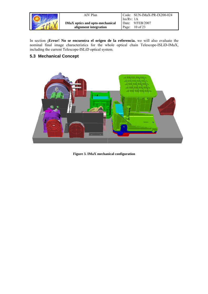
5.3 Mechanical Concept
Figure 3. IMaX mechanical configuration

AIV Plan
IMaX optics and opto-mechanical alignment integration
Code: SUN-IMaX-PR-IX200-024 Iss/Rv: 1A Date: 9/FEB/2007 Page: 11 of 23
6. INTA TEST FACILITIES
6.1 Clean Room Area Laboratory
The features foreseen in the clean room and its main instrumentation are the following:
• Clean room area 10000 class, surface 45 m2. Includes a thermal vacuum chamber, three optical tables and main instrumentation for optical integration and characterization.
• Visible and IR MTF Test benches
Equipment for testing the optical quality of optical systems by means the Modulation Transfer Function (MTF). A light line is projected on the optical system and analyzing the image of the Line Transfer Function is obtained the Optical Transfer Function (OTF), which module correspond the MTF. The optical bench offers the possibility to work in the IR wavelength bands 3-5 micron and 8–12 micron, using for this an IR illumination source and a IR mono-element detector cooled by liquid nitrogen. Both finite and infinite conjugate systems can be tested. The MTF is presented in real time.
• Theodolites:
This Instrument allows the measurement of horizontal and vertical angles with very high precision. The equipment let to measure the optical axis of instruments with respect to the mechanical axis with precision lower than 0.5 arcsec. INTA has various theodolites Leica T3000 and various Total-station (with rangefinder and automatically controlled) and has great experience in working with this equipment in triangulation to obtain high precision axial measurements.
Figure 4. Theodolite Leica T3000
• Autocollimator
The autocollimator is similar to the theodolite but has a higher optical aperture and focal length allowing a more easy location of the reflected beam through complicated windows or poor illuminated conditions. The equipment is easily combined with the

AIV Plan
IMaX optics and opto-mechanical alignment integration
Code: SUN-IMaX-PR-IX200-024 Iss/Rv: 1A Date: 9/FEB/2007 Page: 12 of 23
theodolites assuring a very compact equipment. The Nikon 6D autocollimator provides an exceptional accuracy and reliability required for demanding measurements such as checking parallelism of end surfaces, squareness, flatness of surface plates, straightness of movement and calibration of rotary stages.
The typical specifications are: • Telescope Magnification:38x
• Objective: f=300mm; effective aperture: 70mm
• Measuring Range: 30 minutes of arc.
• Minimum Reading: 0.5 seconds of arc.
• Readout System: Adjustment in viewfield and reading on micrometer
• Measuring Accuracy: 0.5 second of arc within a range of 5 minutes of arc.
• Phase Shifting Interferometer (PSI)
The Zygo GPI-XP Phase Modulation Interferometer system provides non contact measurement of flat or spherical surfaces, and transmitted wavefront measurement of optical components and assemblies. INTA has many reference spheres to adapt the interferometer to any optical instrument.
The high accuracy (< λ/100 P-V) assure the correct measurement of interferometric wavefront for testing End-to-End systems or optical instrument, and it is ideal to perform measurements of alignment verification and optical quality of pre- and post Thermal Vacuum and Vibration testing.
Figure 5. ZYGO interferometer GPI-XP
• On axis Differential Interferometer (ODI)
The equipment (Agilent 10719A) is basically a very compact interferometer allowing differential measurements between a measurement mirror and a reference mirror. The sub micron resolution (better than 5 nm.), friendly use and long range of measurements

AIV Plan
IMaX optics and opto-mechanical alignment integration
Code: SUN-IMaX-PR-IX200-024 Iss/Rv: 1A Date: 9/FEB/2007 Page: 13 of 23
(up to 10m.) make this system as ideal to analyze optical alignment in vacuum conditions with complicated geometries.
• Control Measurement Machine
Figure 6. 7-axis FARO Platinum series
The Platinum FaroArm’s .0005" accuracy is used for inspecting, reverse engineer or perform CAD-to-Part-analysis on parts, fixtures and assemblies with great precision. It also features true portability and improved ergonomics.
The Platinum FaroArm includes extended-use on-board batteries. The portable cmm platform has a universal 3.5" mounting ring for easy adaptability, while the base offers mounting options that afford "measure-where-you make-it capability.
The arm itself is internally counterbalanced for "neutral buoyancy" and fatigue-free usage. In fact, overload sensors prevent users from stressing the arm and help ensure precise measurement.
FARo arm has 7 axis. With it's pistol grip handle, the seventh axis models provide greater flexibility when used with custom probes; and expands capabilities with the optional FARO Laser Line Probe. Inverted configurations are also available for mounting upside-down in confined spaces or hard to reach areas.
FaroArm Test Methods
1) Single Point Articulation Performance Test (SPAT): The probe of the FaroArm is placed within a conical socket, and individual points are measured from multiple approach directions. Each individual point measurement is analyzed as a range of deviations about the average value for point location. This test is the most recognized method for determining articulating measurement machine repeatability.
2) Volumetric Performance: Determined by using traceable length artifacts, which are measured at various locations and orientations throughout the working volume of the FaroArm. This test is the most recognized method for determining articulating measurement machine accuracy.
• Long Distance Microscope.
This instrument is used to assemble the Focal Plane unit with the optical system. For this operation is needed to take a reference of the imaginary focal plane and mount the active area just in this plane. This instrument allows working from a working distance between 15 and 45 cm. The catadioptric objective included in the instrument allows

AIV Plan
IMaX optics and opto-mechanical alignment integration
Code: SUN-IMaX-PR-IX200-024 Iss/Rv: 1A Date: 9/FEB/2007 Page: 14 of 23
getting a resolution better than 2 microns, enough to meet any basically integration requirement.

AIV Plan
IMaX optics and opto-mechanical alignment integration
Code: SUN-IMaX-PR-IX200-024 Iss/Rv: 1A Date: 9/FEB/2007 Page: 15 of 23
7. OPTOMECHANICAL ASSEMBLY 7.1 Subsystems footprint verification
Subsystems footprint flatness should have a tight tolerance between their respective perpendiculars. Perpendicular to each footprint area will be measured by means of the Control Metrology Machine and then compared all of them. Objective of this operation is assuring that all the subsystems are assembled in the same plane
Control Metrology Machine will be attached to the optical bench. Footprint areas corresponding to F4, mounting 1, collimator holder, etalon, beamsplitter mounting and cameras will be tested. Corresponding planes and parallelism between them will be then derived.
7.2 Alignment cube location
Figure 7. Internal alignment cube location
An alignment cube is needed to have an external optical reference. The cube will be located in the closest corner to F4 mounting. It must be parallel to the optical bench surface. Positioning will be done with a theodolite and some other cubes located temporary on the subsystem footprint areas. This cube will be used only as optical reference during internal IMaX alignment procedure. Another cube or cubes will be available to perform IMaX integration with SUNRISE. The cube described during this operation could be covered by the external IMaX cover.
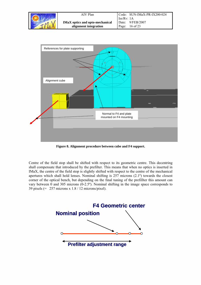
7.3 Mounting F4 (Optical Support 0, IX-OP-OM-050)
A disk with a pinhole in its centre will be placed in F4 mounting (Optical Support 0, IX-OP-OM-050). The three mechanical references which can be found on its mounting will be used as well for leaning a small plane-parallel plate for retro-reflection purposes. Align the normal to this plate with normal to the reference cube. This operation will be carried out with a theodolite. Once aligned, a He-Ne laser will be inserted by the pin-hole perpendicular to the plate. F4 mounting has not got vertical adjustment, so the height reached during this operation by the centre of F4 will be used as the line of sight height of IMaX. The mechanical design of F4 mounting shall allow changing easily the field stop position between room and vacuum positions. Axial difference of these two positions is 1,48 mm.
AIV Plan
IMaX optics and opto-mechanical alignment integration
Code: SUN-IMaX-PR-IX200-024 Iss/Rv: 1A Date: 9/FEB/2007 Page: 16 of 23
References for plate supporting
Alignment cube
Normal to F4 and platemounted on F4 mounting
References for plate supporting
Alignment cube
Normal to F4 and platemounted on F4 mounting
Figure 8. Alignment procedure between cube and F4 support.
Centre of the field stop shall be shifted with respect to its geometric centre. This decentring shall compensate that introduced by the prefilter. This means that when no optics is inserted in IMaX, the centre of the field stop is slightly shifted with respect to the centre of the mechanical apertures which shall hold lenses. Nominal shifting is 257 microns (2.1º) towards the closest corner of the optical bench, but depending on the final tuning of the prefillter this amount can vary between 0 and 305 microns (0-2.5º). Nominal shifting in the image space corresponds to 39 pixels (= 257 microns x 1.8 / 12 microns/pixel).
F4 Geometric center
Prefilter adjustment range
Nominal positionF4 Geometric center
Prefilter adjustment range
Nominal position

AIV Plan
IMaX optics and opto-mechanical alignment integration
Code: SUN-IMaX-PR-IX200-024 Iss/Rv: 1A Date: 9/FEB/2007 Page: 17 of 23
7.4 Preliminary centring
Using the laser direction mount, centre and orientate remainder mountings: pre-filter and ROCLI´s mount (Optical Support 1, IX-OP-OM-100), doublet mount (Optical Support 2, IX-OP-OM-200), mirrors mount (Optical Support 3, IX-OP-OM-400) and beamsplitter mount (Optical Support 4, IX-OP-OM-500). Place a plate with recorded reticule in the theoretical position of the image plane, where CCD cameras should go. Mounts will be provided with their centring tools during this operation. No optics is yet inserted but the three mirrors (two of them in the etalon mount and the other in ROCLIs mount). Centring and orientation will be done using the laser reference and the theodolite. Laser will be used for passing the light through the centre pinhole in each mounting, and theodolite for orientation (leaning a plane parallel plate in a plane perpendicular to the mechanical axis of the component). Use shims where needed when laser height cannot be reached.
LáserHe-Ne
= útiles de centrado
Ejes paralelos
LáserHe-Ne
= útiles de centrado
Ejes paralelos
Figure 9. Set-up for preliminary centering
7.5 Folding mirrors adjustment
Folding mirrors in Optical Support 3 (IX-OP-OM-400) require a previous and external alignment procedure prior to its integration on IMaX optical bench. During this pre-operation it shall be assured that:

AIV Plan
IMaX optics and opto-mechanical alignment integration
Code: SUN-IMaX-PR-IX200-024 Iss/Rv: 1A Date: 9/FEB/2007 Page: 18 of 23
• Angle between normal of the two mirrors is 90 degrees. This operation will be done with a theodolite, verifying that the system is working as a “retro-projector” (eyepiece reticule and returned reticule are superimposed)
• Angle between normal to the first mirror and input mechanical reference at the aperture is 45 degrees, as is shown in Figure 10
Figure 10. Set-up for folding mirrors integration and adjustment. Translation and tilt adjustment is
critical to avoid any chief ray displacement at the output of the second mirror. Figure shows the angle to be measured.
Once integrated, the subsystems is brought to the optical bench and oriented by autocollimation in the same way that the others subsystems (plane parallel plate on the mechanical reference plane and centring tools).
7.6 Fine adjustment
Place theodolite parallel with optical axis. Remove centring tool from F4 support. Place a reflecting plane-parallel plate in ROCLIs mount (removing the structure which holds the pre-filter), and adjust mount orientation by auto-collimation. Focus theodolite on centring tool inserted in ROCLIs mount and refine the mount centring. When the theodolite is focussed onto the centring tool is possible to distinguish both the projected reticule and the centring tool small pin-hole. To do this better use a CCD camera and capture the image of the projected reticule over the pin-hole. Using Matlab features included in the Image Processing Toolbox, is possible to achieve a high resolution centring, in the order of one image pixel.
Once ROCLIs mount is so centred and aligned, remove the centring tool and repeat operation with the next mount, i.e. the doublet mount. Once finished, continue with the next one and so on. Further components will show larger projected reticules because of their distances to the theodolite. This fact could decrease adjustment resolution. Reticule thickness is foreseen between one and five millimetres. Use of the digital technique to refine adjustment avoids loss of accuracy during the alignment process.
AIV Plan
IMaX optics and opto-mechanical alignment integration
Code: SUN-IMaX-PR-IX200-024 Iss/Rv: 1A Date: 9/FEB/2007 Page: 19 of 23
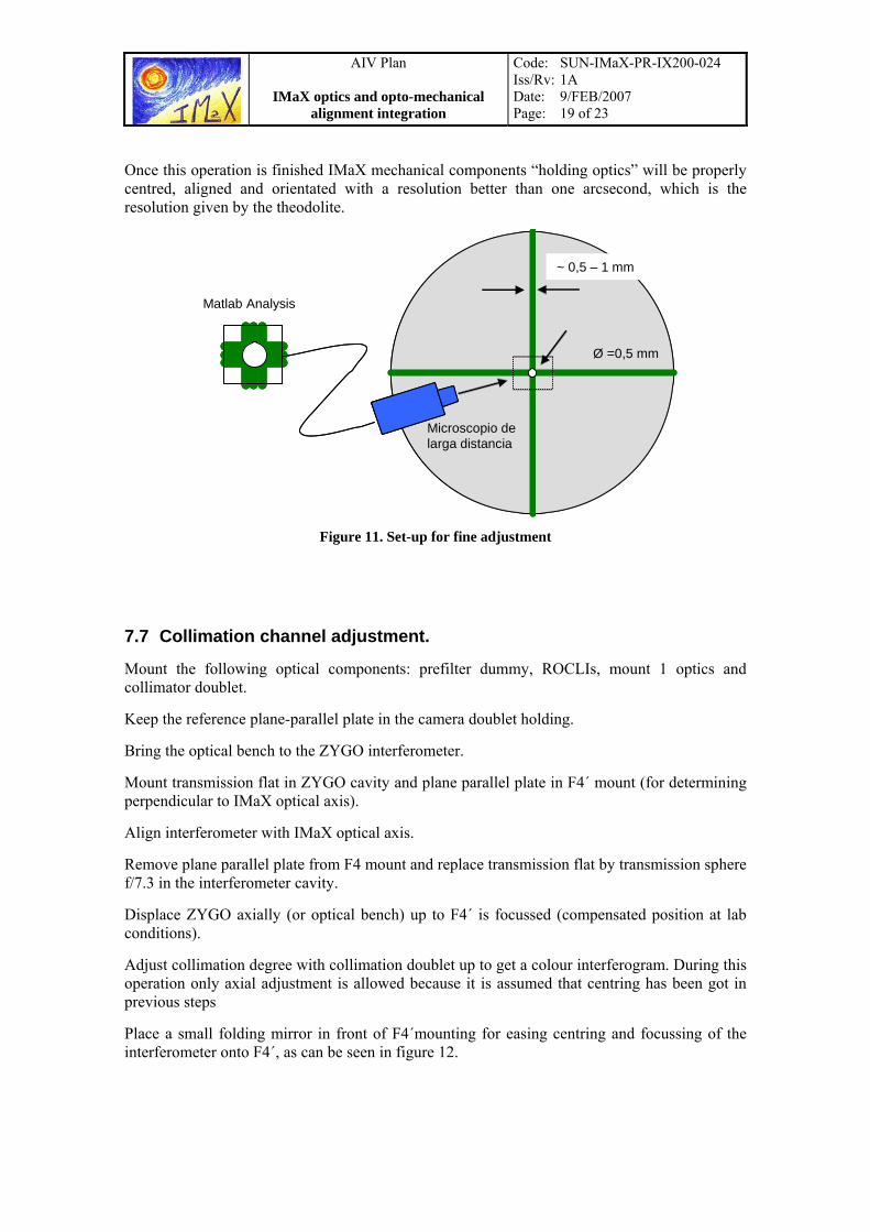
Once this operation is finished IMaX mechanical components “holding optics” will be properly centred, aligned and orientated with a resolution better than one arcsecond, which is the resolution given by the theodolite.
~ 0,5 – 1 mm
Ø =0,5 mm
Matlab Analysis
Microscopio de larga distancia
~ 0,5 – 1 mm
Ø =0,5 mm
Matlab Analysis
Microscopio de larga distancia
Figure 11. Set-up for fine adjustment
7.7 Collimation channel adjustment.
Mount the following optical components: prefilter dummy, ROCLIs, mount 1 optics and collimator doublet.
Keep the reference plane-parallel plate in the camera doublet holding.
Bring the optical bench to the ZYGO interferometer.
Mount transmission flat in ZYGO cavity and plane parallel plate in F4´ mount (for determining perpendicular to IMaX optical axis).
Align interferometer with IMaX optical axis.
Remove plane parallel plate from F4 mount and replace transmission flat by transmission sphere f/7.3 in the interferometer cavity.
Displace ZYGO axially (or optical bench) up to F4´ is focussed (compensated position at lab conditions).
Adjust collimation degree with collimation doublet up to get a colour interferogram. During this operation only axial adjustment is allowed because it is assumed that centring has been got in previous steps
Place a small folding mirror in front of F4´mounting for easing centring and focussing of the interferometer onto F4´, as can be seen in figure 12.

AIV Plan
IMaX optics and opto-mechanical alignment integration
Code: SUN-IMaX-PR-IX200-024 Iss/Rv: 1A Date: 9/FEB/2007 Page: 20 of 23
f/7.3
f/25
ZYGO
f/7.3
f/25
ZYGO
Figure 12. Collimation channel adjustment. Folding mirror located in front of F4 includes tip, tilt and displacement adjustment to facilitate centring and orientation of the beam coming from the interferometer. With this mirror it is not necessary moving the interferometer.
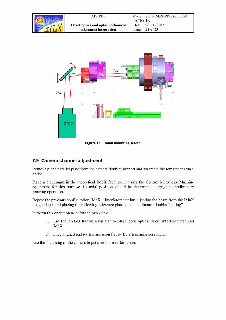
7.8 Etalon mounting (Etalon Support, IX-OP-OM-300)
Etalon is mounted once the collimation channel has been adjusted, and taking into account that this component works in collimated beam.
The plane parallel plate, or mirror, located in the camera doublet holding is removed, and maintaining the same IMaX + interferometer set-up than in the step before, we have to search the colour interferogram coming from the first side of the etalon. With this operation we are assuring that the etalon is perpendicular to the optical axis.
Etalon tilt adjustment will be done later, when the two cameras are mounted.
AIV Plan
IMaX optics and opto-mechanical alignment integration
Code: SUN-IMaX-PR-IX200-024 Iss/Rv: 1A Date: 9/FEB/2007 Page: 21 of 23
f/7.3
f/25
ZYGO
f/7.3
f/25
ZYGO
Figure 13. Etalon mounting set-up.
7.9 Camera channel adjustment
Remove plane parallel plate from the camera doublet support and assemble the remainder IMaX optics.
Place a diaphragm in the theoretical IMaX focal point using the Control Metrology Machine equipment for this purpose. Its axial position should be determined during the preliminary centring operation.
Repeat the previous configuration IMaX + interferometer but injecting the beam from the IMaX image plane, and placing the reflecting reference plate in the “collimator doublet holding”.
Perform this operation as before in two steps:
1) Use the ZYGO transmission flat to align both optical axes: interferometer and IMaX.
2) Once aligned replace transmission flat by f/7.2 transmission sphere.
Use the focussing of the camera to get a colour interferogram.
AIV Plan
IMaX optics and opto-mechanical alignment integration
Code: SUN-IMaX-PR-IX200-024 Iss/Rv: 1A Date: 9/FEB/2007 Page: 22 of 23
f/7.3
ZYGO
f/7.3
ZYGO
f/7.3
ZYGO
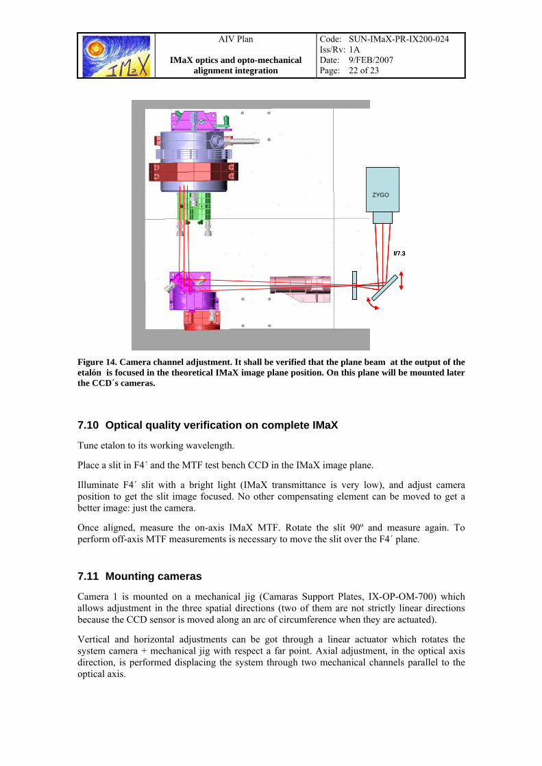
Figure 14. Camera channel adjustment. It shall be verified that the plane beam at the output of the etalón is focused in the theoretical IMaX image plane position. On this plane will be mounted later the CCD´s cameras.
7.10 Optical quality verification on complete IMaX
Tune etalon to its working wavelength.
Place a slit in F4´ and the MTF test bench CCD in the IMaX image plane.
Illuminate F4´ slit with a bright light (IMaX transmittance is very low), and adjust camera position to get the slit image focused. No other compensating element can be moved to get a better image: just the camera.
Once aligned, measure the on-axis IMaX MTF. Rotate the slit 90º and measure again. To perform off-axis MTF measurements is necessary to move the slit over the F4´ plane.
7.11 Mounting cameras
Camera 1 is mounted on a mechanical jig (Camaras Support Plates, IX-OP-OM-700) which allows adjustment in the three spatial directions (two of them are not strictly linear directions because the CCD sensor is moved along an arc of circumference when they are actuated).
Vertical and horizontal adjustments can be got through a linear actuator which rotates the system camera + mechanical jig with respect a far point. Axial adjustment, in the optical axis direction, is performed displacing the system through two mechanical channels parallel to the optical axis.
AIV Plan
IMaX optics and opto-mechanical alignment integration
Code: SUN-IMaX-PR-IX200-024 Iss/Rv: 1A Date: 9/FEB/2007 Page: 23 of 23
A one millimetre displacement in the vertical and horizontal actuator produces a slight tilt in the plane of the sensor, estimated in approximately 60 microns measured between two extreme pixels.
1 mm
30º
CCD
62 µm
1 mm
30º
CCD
62 µm
Figure 15. Effect of the CCD inclination when linear actuator is operated.
Before the camera is mounted the focal plane position shall be identified when the MTF is measured. Before removing the microscope objective of the MTF equipment a reticule will be located in the image plane position. Once the microscope objective of the MTF equipment is removed the reticule is monitored with a microscope (a long distance microscope, for instance).
Once the microscope is focused remove the reticule and replace with the mechanical jig which includes the camera. Adjust the sensor area in the three spatial directions in order to get the right CCD positioning.
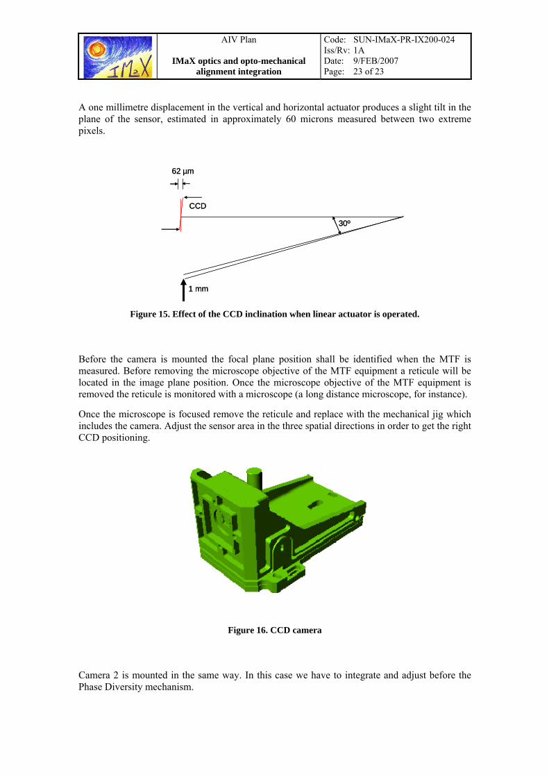
Figure 16. CCD camera
Camera 2 is mounted in the same way. In this case we have to integrate and adjust before the Phase Diversity mechanism.