DESIGN PRINCIPLES: MECHANICAL VENTILATORS
41
DESIGN PRINCIPLES: MECHANICAL VENTILATORS Prof. Yasser Mostafa Kadah – www.k-space.org EE 497 – Spring 2015
-
Upload
phungthien -
Category
Documents
-
view
229 -
download
2
Transcript of DESIGN PRINCIPLES: MECHANICAL VENTILATORS
DESIGN PRINCIPLES:
MECHANICAL VENTILATORS
Prof. Yasser Mostafa Kadah – www.k-space.orgEE 497 – Spring 2015

Recommended References
Iain Mackenzie, Core Topics in Mechanical Ventilation, Cambridge University
Press, Cambridge, 2008. (ISBN: 978-0521867818)
Rüdiger Kramme, Klaus-Peter Hoffmann, Robert S. Pozos (Eds.), Springer
Handbook of Medical Technology, Springer-Verlag, Berlin, 2011. (ISBN:
978-3-540-74657-7)
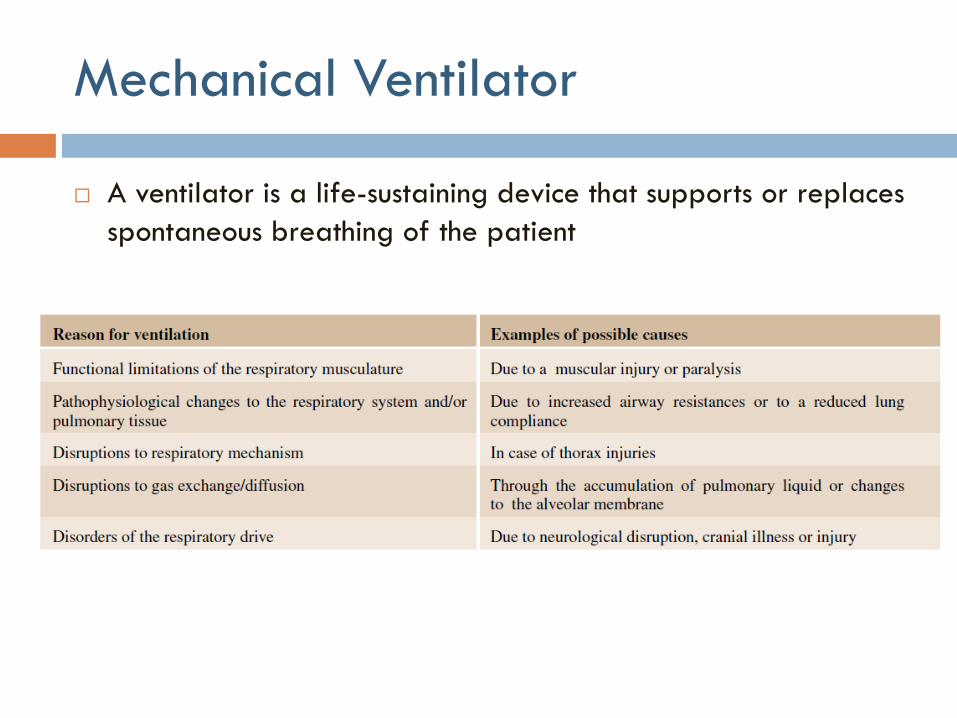
Mechanical Ventilator
A ventilator is a life-sustaining device that supports or replaces
spontaneous breathing of the patient
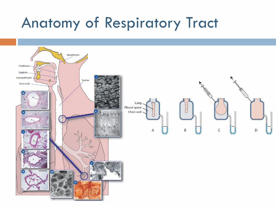
Anatomy of Respiratory Tract
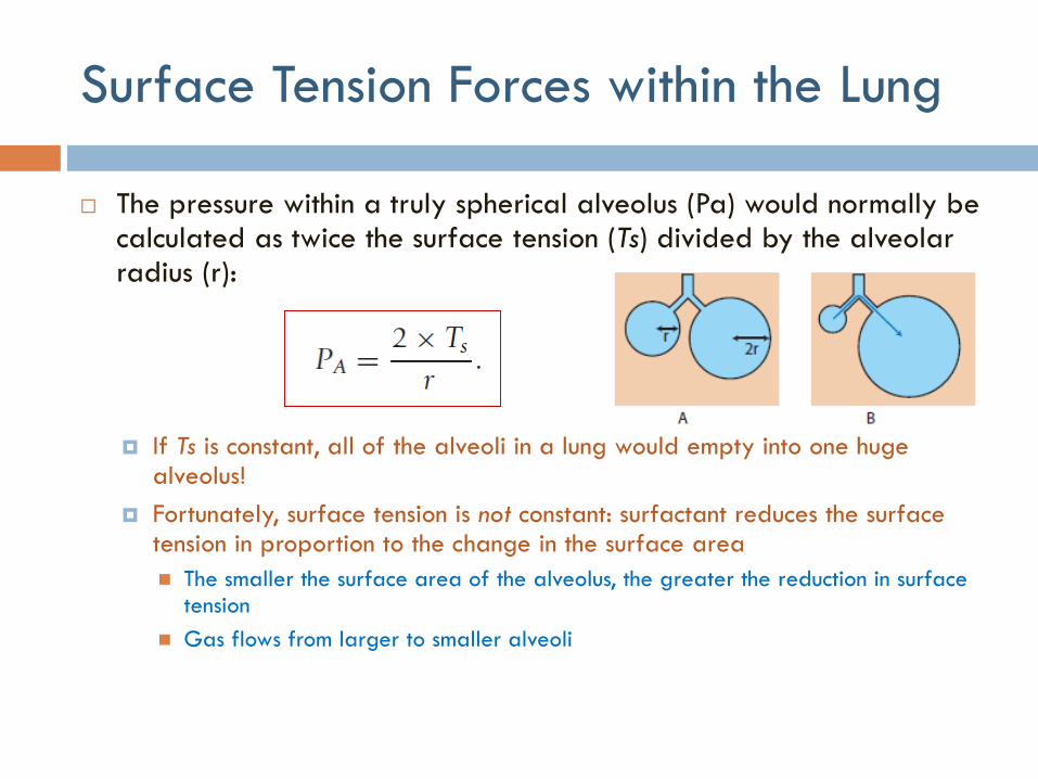
The pressure within a truly spherical alveolus (Pa) would normally be calculated as twice the surface tension (Ts) divided by the alveolar radius (r):
If Ts is constant, all of the alveoli in a lung would empty into one huge alveolus!
Fortunately, surface tension is not constant: surfactant reduces the surface tension in proportion to the change in the surface area
The smaller the surface area of the alveolus, the greater the reduction in surface tension
Gas flows from larger to smaller alveoli
Surface Tension Forces within the Lung
Lung Compliance
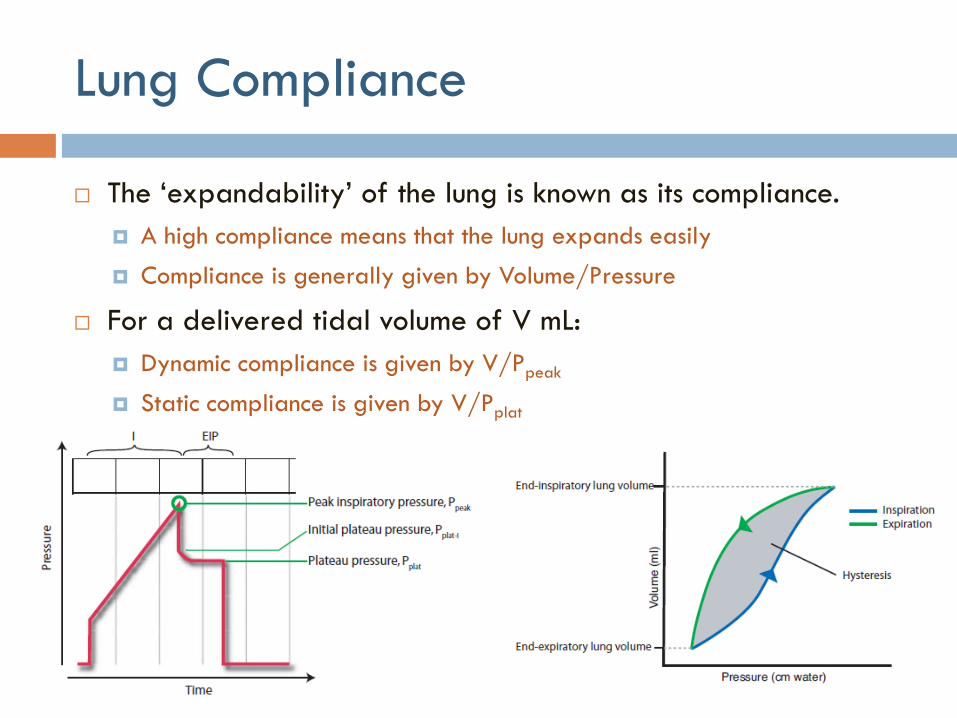
The ‘expandability’ of the lung is known as its compliance.
A high compliance means that the lung expands easily
Compliance is generally given by Volume/Pressure
For a delivered tidal volume of V mL:
Dynamic compliance is given by V/Ppeak
Static compliance is given by V/Pplat
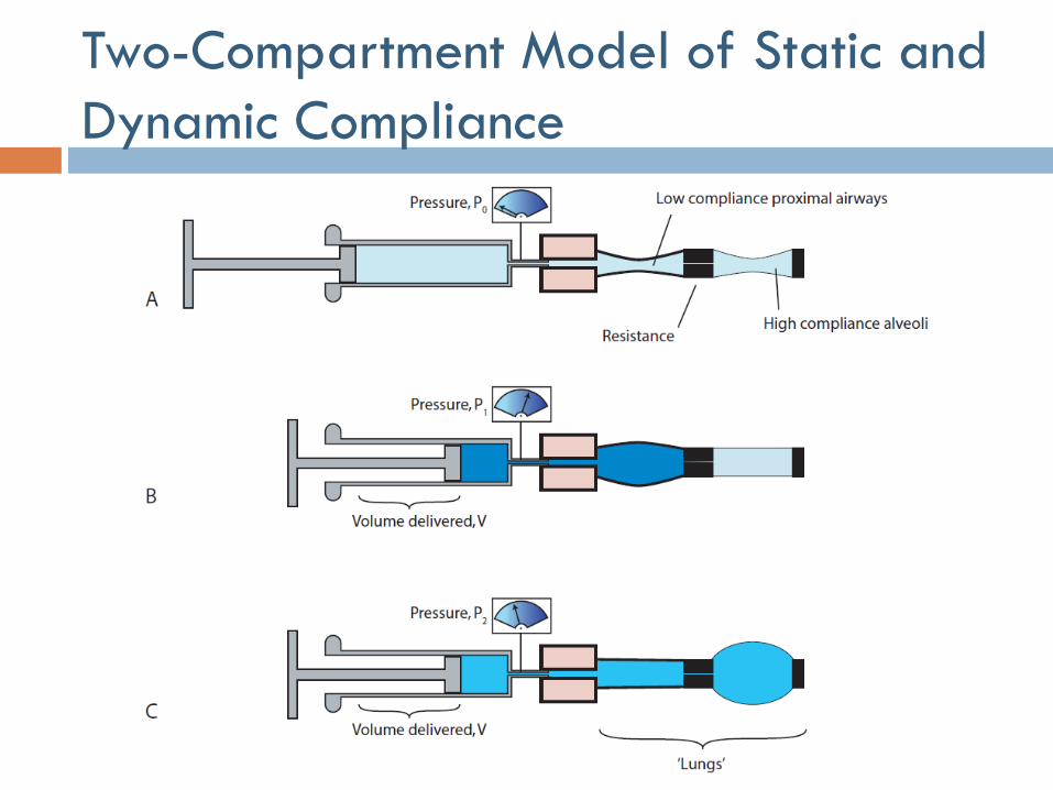
Two-Compartment Model of Static and
Dynamic Compliance
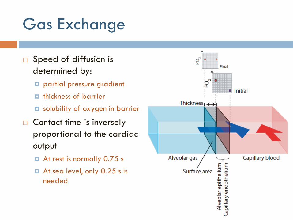
Gas Exchange
Speed of diffusion is
determined by:
partial pressure gradient
thickness of barrier
solubility of oxygen in barrier
Contact time is inversely
proportional to the cardiac
output
At rest is normally 0.75 s
At sea level, only 0.25 s is
needed
Ventilator Tasks
Oxygenation of the patient
Provide and supply the patient with a mixture of oxygen and air
Partial or total assumption of respiratory work
Generate and dose defined gas flow and respiratory pressure
Monitoring of the device and patient
Generate alarms and visualize changes
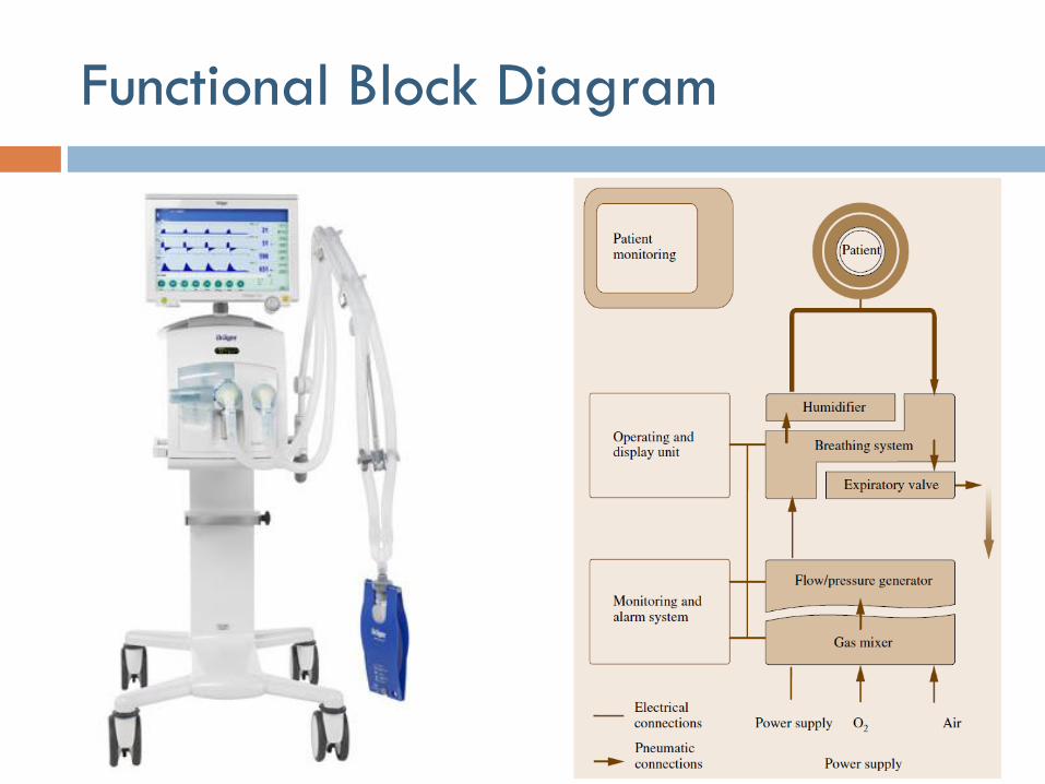
Functional Block Diagram
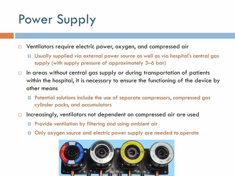
Power Supply
Ventilators require electric power, oxygen, and compressed air
Usually supplied via external power source as well as via hospital’s central gas
supply (with supply pressure of approximately 3–6 bar)
In areas without central gas supply or during transportation of patients
within the hospital, it is necessary to ensure the functioning of the device by
other means
Potential solutions include the use of separate compressors, compressed gas
cylinder packs, and accumulators
Increasingly, ventilators not dependent on compressed air are used
Provide ventilation by filtering and using ambient air
Only oxygen source and electric power supply are needed to operate

Gas Mixer
Gas mixer allows the user to vary the oxygen concentration of inspiratory
gas between 21% and 100% by volume
Mechanical gas mixers (old technology)
Electronically-controlled gas mixer integrated in ventilator (standard now)
Gas mixers usually responsible for ensuring that breathing gas to be
supplied is prepared and delivered in required quantity and rate
It is often the threshold ranges which pose the greatest challenges to these
metering systems
For volume of 20 ml with an oxygen concentration of 30% by volume, 17.7ml of
gas must be delivered via compressed air valve and 2.3ml via oxygen valve
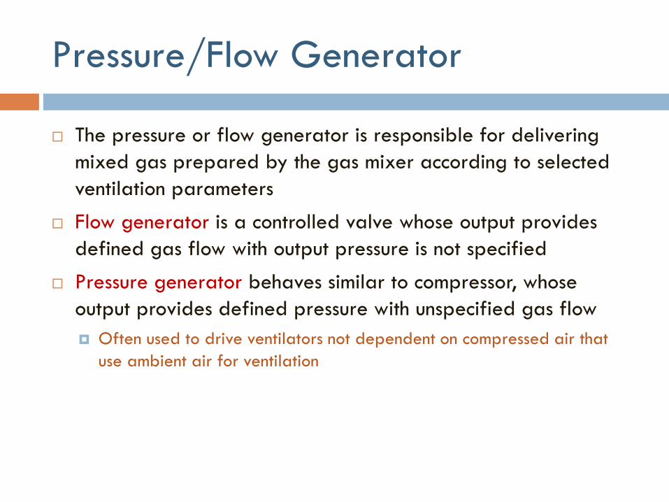
Pressure/Flow Generator
The pressure or flow generator is responsible for delivering
mixed gas prepared by the gas mixer according to selected
ventilation parameters
Flow generator is a controlled valve whose output provides
defined gas flow with output pressure is not specified
Pressure generator behaves similar to compressor, whose
output provides defined pressure with unspecified gas flow
Often used to drive ventilators not dependent on compressed air that
use ambient air for ventilation

Breathing System
Breathing system forms interface between patient and the ventilator
Clinical ventilators are usually connected to patient via inspiratory and expiratory hose (dual-hose circuit).
Expiratory valve is closed during the inspiratory phase.
Gas flow delivered through inspiratory port passes through breathing gas humidifier before entering patient’s lungs
To make it adapted to climatic conditions in patient’s lungs
After inspiratory phase, patient exhales when expiratory valve is opened
Expiratory gas passes through ventilator again, but not reused for following inspiration
Based on this characteristic, the breathing systems of ventilators are also referred to as non-rebreathing circuits
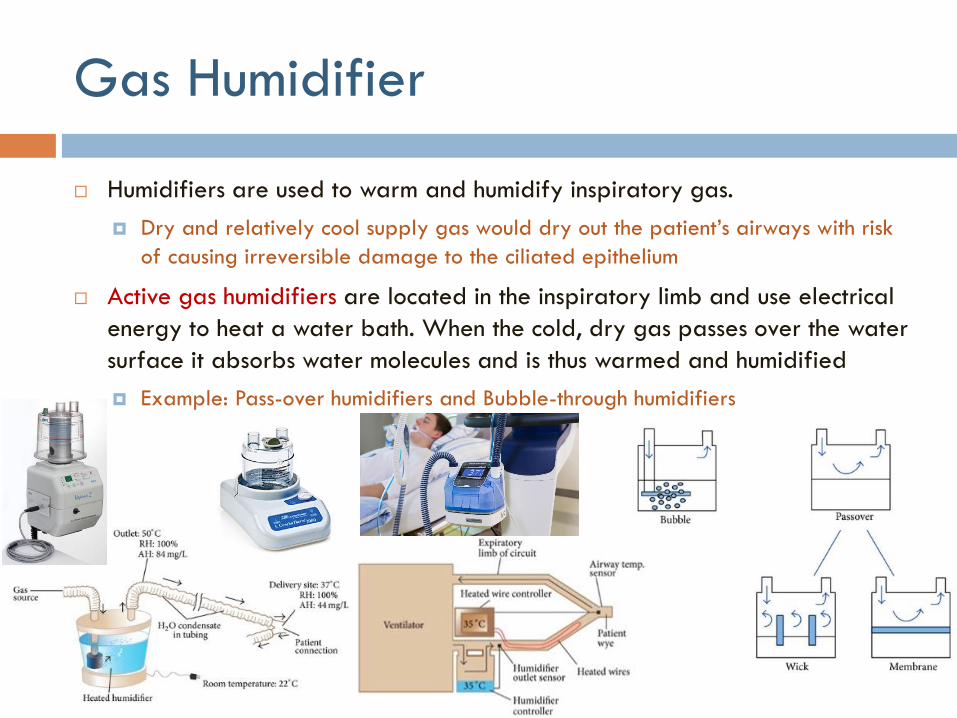
Gas Humidifier
Humidifiers are used to warm and humidify inspiratory gas.
Dry and relatively cool supply gas would dry out the patient’s airways with risk
of causing irreversible damage to the ciliated epithelium
Active gas humidifiers are located in the inspiratory limb and use electrical
energy to heat a water bath. When the cold, dry gas passes over the water
surface it absorbs water molecules and is thus warmed and humidified
Example: Pass-over humidifiers and Bubble-through humidifiers

Gas Humidifier
Passive breathing gas humidifiers, termed heat and moisture exchangers
(HMEs), are placed close to patient and designed to buffer significant
fraction of moisture and heat expired by patient.
Retained moisture is then used to condition inspired gas passing through HME
during next inspiration
Using HME together with active breathing gas humidifier in single breathing
circuit is not permitted as it would significantly impair resistance of HME
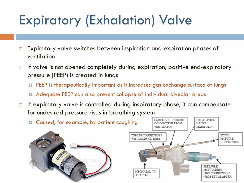
Expiratory (Exhalation) Valve
Expiratory valve switches between inspiration and expiration phases of
ventilation
If valve is not opened completely during expiration, positive end-expiratory
pressure (PEEP) is created in lungs
PEEP is therapeutically important as it increases gas exchange surface of lungs
Adequate PEEP can also prevent collapse of individual alveolar areas
If expiratory valve is controlled during inspiratory phase, it can compensate
for undesired pressure rises in breathing system
Caused, for example, by patient coughing
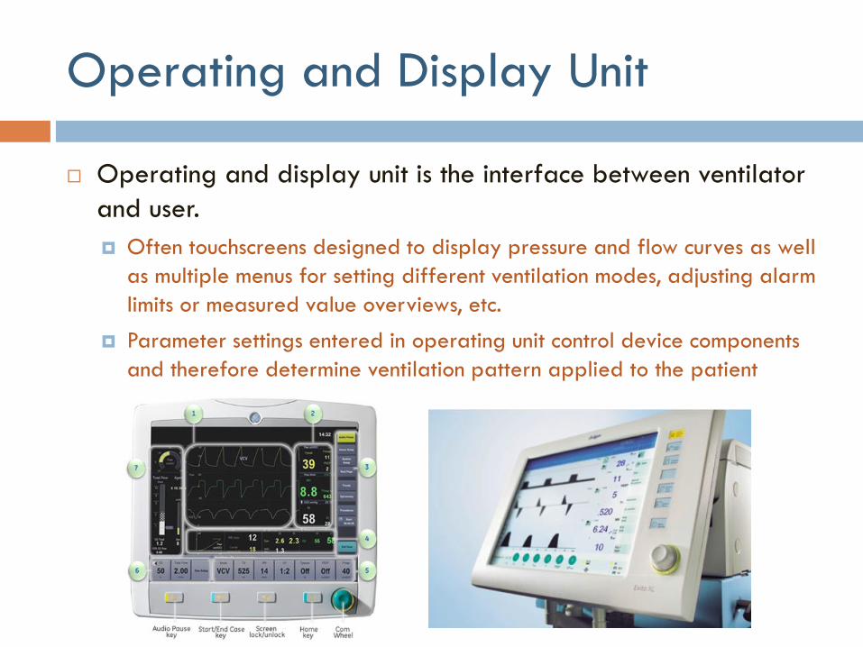
Operating and Display Unit
Operating and display unit is the interface between ventilator
and user.
Often touchscreens designed to display pressure and flow curves as well
as multiple menus for setting different ventilation modes, adjusting alarm
limits or measured value overviews, etc.
Parameter settings entered in operating unit control device components
and therefore determine ventilation pattern applied to the patient
Alarm System
Ensures that ventilation parameters set in operating and display
unit are actually applied
Issues audible and visual alarms to alert staff to critical changes
in the patient’s condition or technical malfunctions
Monitors the following:
Inspiratory oxygen concentration (controlled by the gas mixer)
Ventilation Pressure and Volume (to monitor the pressure/flow generator)
Inspiratory breathing gas temperature (when using active gas humidifier)
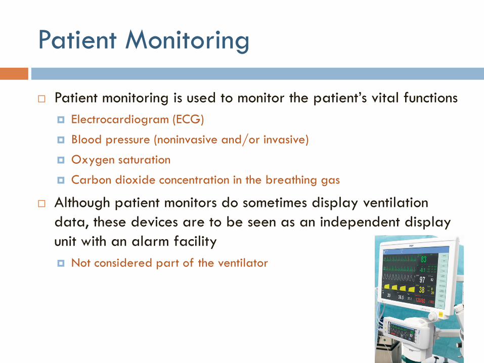
Patient Monitoring
Patient monitoring is used to monitor the patient’s vital functions
Electrocardiogram (ECG)
Blood pressure (noninvasive and/or invasive)
Oxygen saturation
Carbon dioxide concentration in the breathing gas
Although patient monitors do sometimes display ventilation
data, these devices are to be seen as an independent display
unit with an alarm facility
Not considered part of the ventilator
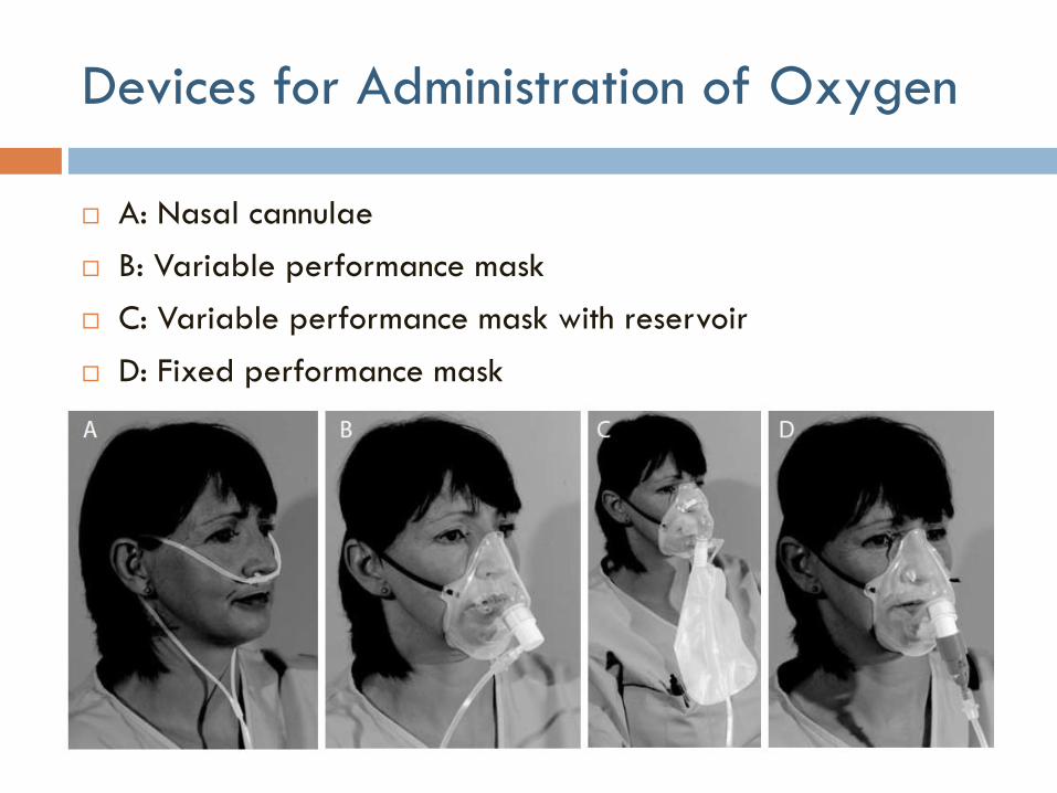
Devices for Administration of Oxygen
A: Nasal cannulae
B: Variable performance mask
C: Variable performance mask with reservoir
D: Fixed performance mask

Venturi Mechanism
If oxygen is supplied to the venturi device at the correct flow
rate, air will be entrained through the vents to provide an air/
oxygen mixture with a specific oxygen concentration

Continuous Flow Systems
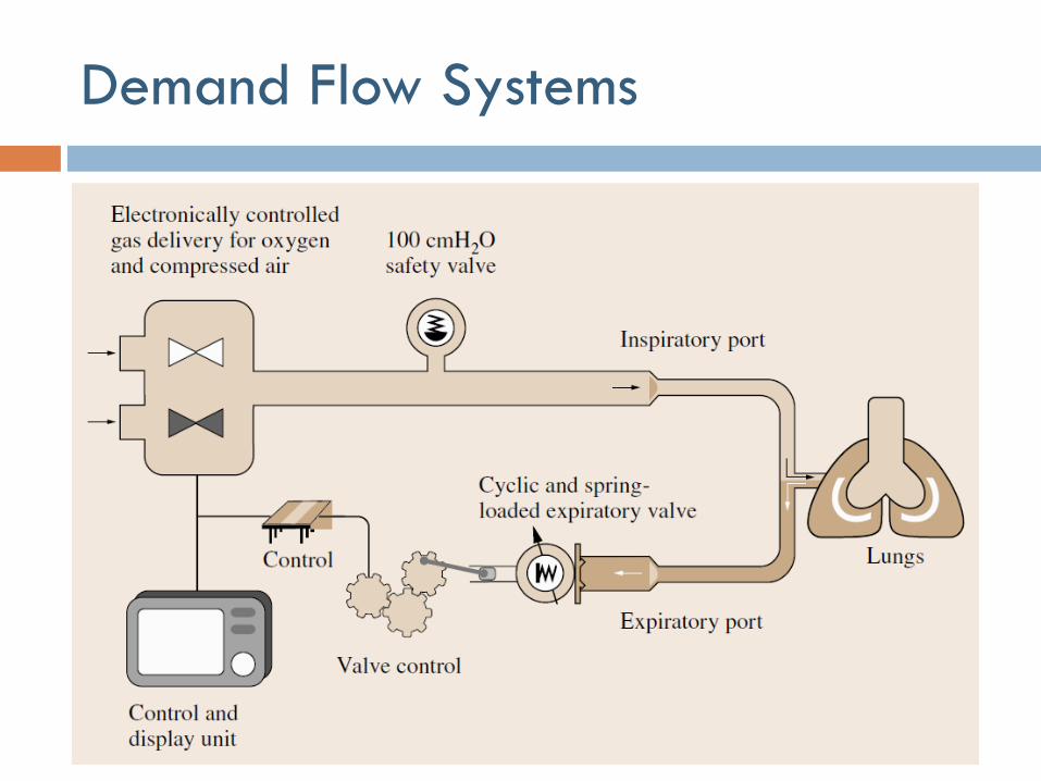
Demand Flow Systems

Forms of Mechanical Ventilation
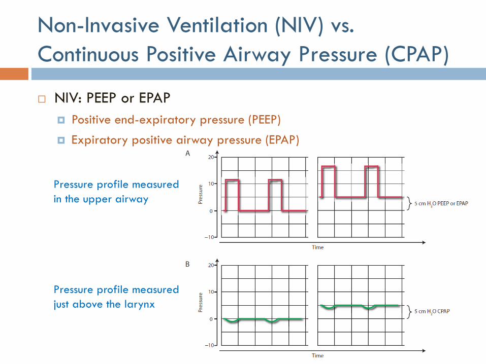
Non-Invasive Ventilation (NIV) vs.
Continuous Positive Airway Pressure (CPAP)
NIV: PEEP or EPAP
Positive end-expiratory pressure (PEEP)
Expiratory positive airway pressure (EPAP)
Pressure profile measured
in the upper airway
Pressure profile measured
just above the larynx
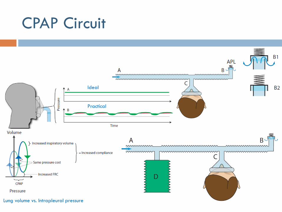
CPAP Circuit
Ideal
Practical
Lung volume vs. Intrapleural pressure

NIV Circuit
Unlike ventilator circuits used for anesthesia or critical care
which have two limbs, one taking fresh gas to the patient and
a second returning expired gas to the ventilator, breathing
circuits for non-invasive ventilation (NIV) only have one limb for
taking fresh gas to the patient
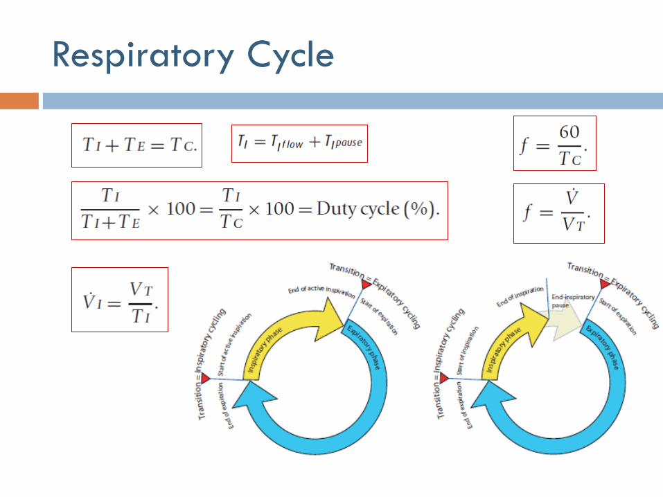
Respiratory Cycle
Trigger, Limit, Cycle, and Baseline
Variables
Trigger variable is one that is measured and used to start
inspiration
Limit variable is one that can reach and maintain a preset
value before inspiration ends (i.e., does not end respiration)
Cycle variable is one that is measured and used to end
respiration
Baseline variable is the parameter controlled during expiration
Pressure control is most practical and used in all modern ventilators
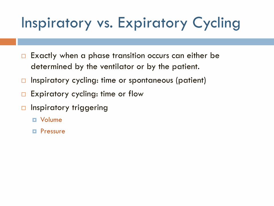
Inspiratory vs. Expiratory Cycling
Exactly when a phase transition occurs can either be
determined by the ventilator or by the patient.
Inspiratory cycling: time or spontaneous (patient)
Expiratory cycling: time or flow
Inspiratory triggering
Volume
Pressure

Mandatory, Spontaneous and
Triggered Inspiratory Cycling
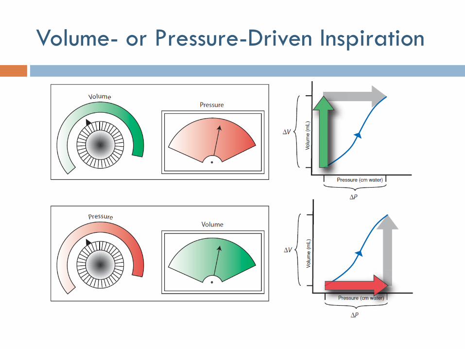
Volume- or Pressure-Driven Inspiration
Classifying Modes of Mechanical
Ventilation
A “mode” of mechanical ventilation can be generally defined
as a predetermined pattern of interaction between a
ventilator and a patient.
There are over 100 names for modes of ventilation on commercially
available mechanical ventilators.
Neither the manufacturing community nor the medical community has
developed a standard taxonomy for modes

Classification of Modes
In mandatory breaths (if present)
What determines inspiratory cycling?
What drives inflation and what is the breath targeted to or limited by?
Is feedback intra-breath or inter-breath?
What determines expiratory cycling?
In triggered breaths (if present)
What breath types are present? Mandatory-pattern, supported or both?
In supported breaths (if present), what drives inflation (control parameter)
and what is the breath targeted to or limited by?
Is feedback intra-breath or inter-breath?
What determines expiratory cycling?
Are spontaneous breaths accommodated and if so, when?
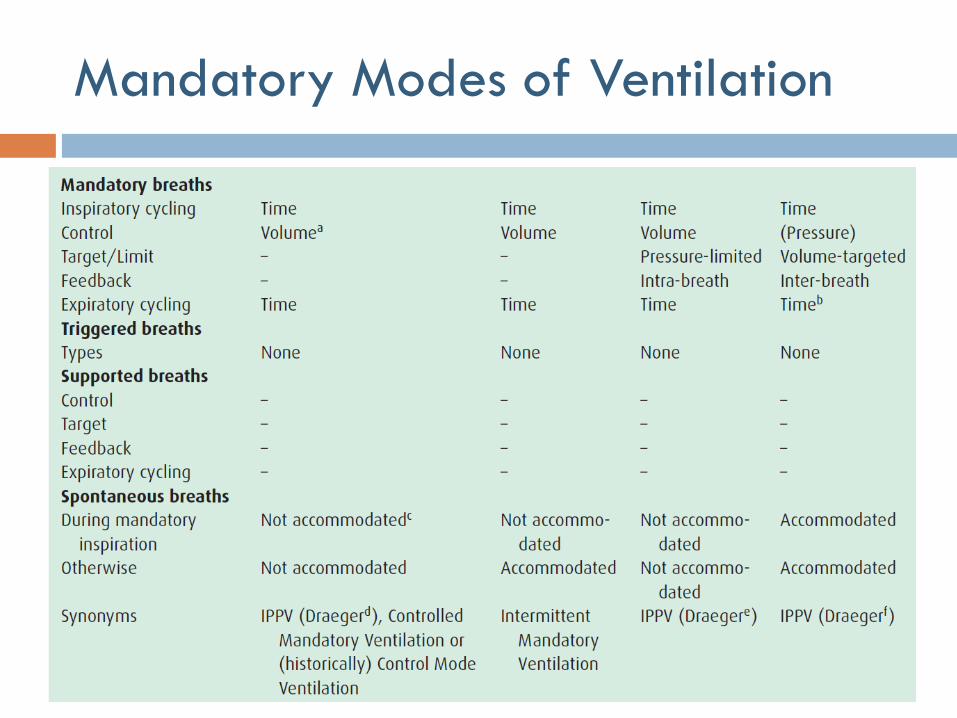
Mandatory Modes of Ventilation
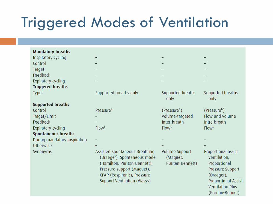
Triggered Modes of Ventilation
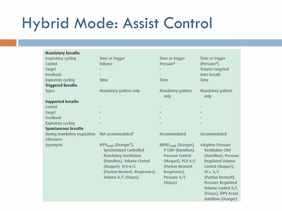
Hybrid Mode: Assist Control
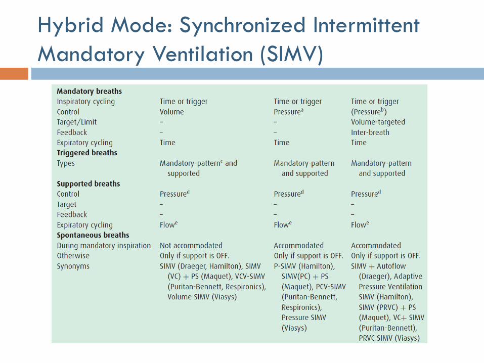
Hybrid Mode: Synchronized Intermittent
Mandatory Ventilation (SIMV)
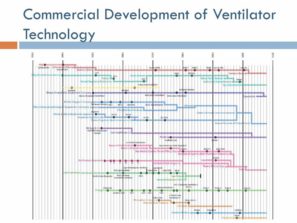
Commercial Development of Ventilator
Technology
Suggested Readings and Assignments
Chapters 1, 3 & 5 of Recommended Reference #1
Chapter 27 of Recommended Reference #2
Problem set posted on web site