Design Principles for Wastewater Pumping Stations
56
Ver.0.6 This is an electronic ESF document that DP-13 is uncontrolled when copied or printed Page 1 of 56 Design Principles for Wastewater Pumping Stations DP-13 Ver. 0.6 Date: 1 November 2021
Transcript of Design Principles for Wastewater Pumping Stations
Ver.0.6 This is an electronic ESF document that DP-13 is uncontrolled when copied or printed Page 1 of 56
Design Principles for
Wastewater Pumping Stations
DP-13
Ver. 0.6
Date: 1 November 2021
Ver.0.6 This is an electronic ESF document that DP-13 is uncontrolled when copied or printed Page 2 of 56
Revision Description Released by Date
0.1 Draft J de Villiers 30/10/2017
0.2 Final draft J de Villiers 28/2/2018
0.3 Working draft for comment J de Villiers 22/6/2018
0.4 Draft to include hybrid and wet-well options.
Document restructured. Internal review
J de Villiers 28/09/2020
0.5 Internal review. Combining DP-06 and DP-13 J de Villiers 17/02/2021
0.6 Draft for public consultation J de Villiers 1/11/2021
Reviewed by:
Rev. 0.5 – Internal working group
Ver.0.6 This is an electronic ESF document that DP-13 is uncontrolled when copied or printed Page 3 of 56
Table of contents
GLOSSARY: TERMS AND ABBREVIATIONS ..................................................................................... 6
PART A – PREAMBLE AND GENERAL DESIGN REQUIREMENTS ........................................................ 8
1. INTRODUCTION ..................................................................................................................... 9
2. REFERENCED STANDARDS ...................................................................................................... 9
2.1. STANDARDS LIST ........................................................................................................................... 9
2.2. Watercare standards ............................................................................................................ 9
2.3. NATIONAL AND INTERNATIONAL STANDARDS ................................................................................... 10
2.4. OTHER PUBLICATIONS .................................................................................................................. 10
3. DESIGN DELIVERABLES ........................................................................................................ 10
4. CRITICALITY AND INFRASTRUCTURE FLEXIBILITY PRINCIPLES ................................................ 11
4.1. DESIGN LIFE ............................................................................................................................... 11
4.2. FUNCTION CLASSES AND CRITICALITY .............................................................................................. 12
4.3. RESILIENCE AND REDUNDANCY ...................................................................................................... 12
4.3.1. Resilience measurements {Table based on the IIMM, 2015 example table 3.2.8} .......... 13
4.3.2. Scoring ............................................................................................................................. 14
4.3.3. Risk .................................................................................................................................. 14
5. SAFETY AND HAZARD MITIGATION ...................................................................................... 14
5.1. SAFETY IN DESIGN GUIDELINES ...................................................................................................... 14
5.2. SAFETY IN FACILITIES DESIGN GUIDELINES ........................................................................................ 14
6. DESIGN PROCESS PUMPING STATIONS ................................................................................. 15
7. PUMPING STATION PLANNING CONSIDERATIONS ................................................................ 20
8. DESIGN OUTPUT FORMAT ................................................................................................... 20
9. PUMPING STATION SITE ...................................................................................................... 20
9.1. SITE GROUND CONDITIONS ........................................................................................................... 21
10. GENERAL DESIGN CONSIDERATIONS ................................................................................. 23
11. DESIGN REVIEW ............................................................................................................... 27
12. CONSTRUCTION ............................................................................................................... 28
13. PUMPING STATION ASSET DATA ...................................................................................... 28
14. TESTING AND HANDOVER ................................................................................................ 28
14.1. COMMISSIONING ..................................................................................................................... 28
14.2. REJECTION OF MATERIALS OR PRODUCTS ..................................................................................... 29
14.3. HANDOVER DOCUMENTS .......................................................................................................... 30
PART B – TYPICAL PUMP STATION DESIGN PARAMETERS ............................................................ 31
1. MATERIAL SELECTION .......................................................................................................... 32
Ver.0.6 This is an electronic ESF document that DP-13 is uncontrolled when copied or printed Page 4 of 56
1.1. WET WELL ................................................................................................................................. 32
1.2. INLET AND OUTLET PIPEWORK ....................................................................................................... 32
1.3. PIPE MATERIAL ........................................................................................................................... 32
1.4. VALVES ..................................................................................................................................... 32
1.5. NON-RETURN VALVES .................................................................................................................. 32
1.6. ISOLATION VALVES ....................................................................................................................... 33
1.7. AIR RELEASE VALVES .................................................................................................................... 33
2. RECEIVING STRUCTURE (DISCHARGE MANHOLE) .................................................................. 33
3. GRIT COLLECTION AND SCREENS .......................................................................................... 33
4. PUMPING STATION INLET SYSTEM ....................................................................................... 33
4.1. GENERAL ................................................................................................................................... 33
4.2. INLET STRUCTURE MATERIAL PREFERENCE ........................................................................................ 34
5. WET WELL INLET ................................................................................................................. 34
6. WET WELL ........................................................................................................................... 34
6.1. SIZE OF THE WET WELL AND LEVELS ................................................................................................ 34
7. PUMP STATION OVERFLOW ................................................................................................. 35
8. WASH/PUMP-OUT .............................................................................................................. 35
9. VENTILATION ...................................................................................................................... 36
10. PUMPING SYSTEM ........................................................................................................... 36
10.1. HYDRAULIC DESIGN .................................................................................................................. 36
10.2. PUMP SELECTION .................................................................................................................... 36
10.3. PUMP PRODUCT REQUIREMENTS ................................................................................................ 38
11. RISING MAIN ................................................................................................................... 38
11.1. GENERAL ............................................................................................................................... 38
11.2. HYDRAULIC DESIGN .................................................................................................................. 38
11.3. RISING MAIN LEVELS ................................................................................................................ 39
11.4. PARALLEL RISING MAINS ........................................................................................................... 39
PART C – PUMP STATION TYPE SPECIFIC CONSIDERATIONS ......................................................... 40
1. WET WELL ONLY SUBMERGED PUMPING STATIONS ............................................................. 41
1.1 ACCESS AND HANDLING ................................................................................................................ 41
1.2 MONITORING AND CONTROL ......................................................................................................... 42
1.3 PUMP INTAKE ............................................................................................................................. 42
1.4 PUMP SELECTION ........................................................................................................................ 42
1.5 WET WELL MATERIAL .................................................................................................................. 42
2. HYBRID PUMPING STATIONS ............................................................................................... 43
2.1 ACCESS AND HANDLING CONSIDERATIONS ....................................................................................... 43
2.2 PUMP PRIMING ........................................................................................................................... 44
2.3 MONITORING AND CONTROL ......................................................................................................... 44
Ver.0.6 This is an electronic ESF document that DP-13 is uncontrolled when copied or printed Page 5 of 56
3. WET WELL / DRY WELL PUMPING STATIONS ........................................................................ 45
3.1 WET WELL ........................................................................................................................ 45
3.1.1 PUMP INTAKES (WET WELL OUTLET PIPEWORK) .................................................................................. 46
3.2 DRY WELL ............................................................................................................................. 46
3.3 ACCESS AND HANDLING CONSIDERATIONS ........................................................................... 46
PART D – ELECTRICAL, CONTROL AND TELEMETRY ...................................................................... 47
1. ELECTRICAL, CONTROL AND TELEMETRY .............................................................................. 48
1.1. ELECTRICAL ................................................................................................................................ 48
1.2. CONTROL SYSTEM AND TELEMETRY ................................................................................................ 48
PART E – INFRASTRUCTURE AND SUPPORT SYSTEMS .................................................................. 50
1. WATER SUPPLY ................................................................................................................... 51
1.1. ABLUTION FACILITIES ................................................................................................................... 51
2. LIGHTING ............................................................................................................................ 51
3. VENTILATION ...................................................................................................................... 51
4. SITE DRAINAGE ................................................................................................................... 51
5. NOISE CONTROL AND VIBRATION ........................................................................................ 52
6. LIFTING EQUIPMENT ........................................................................................................... 52
7. SECURITY, ACCESS AND FIRE ALARMS .................................................................................. 52
8. SIGNAGE ............................................................................................................................. 53
9. SITE ACCESS ROAD .............................................................................................................. 53
10. ODOUR CONTROL ............................................................................................................ 53
APPENDIX A: WATERCARE NETWORK DISCHARGE CONSENT (NDC) EXECUTIVE SUMMARY .......... 54
Ver.0.6 This is an electronic ESF document that DP-13 is uncontrolled when copied or printed Page 6 of 56
Glossary: Terms and abbreviations Accept(ance) a sign-off by Watercare that it is in general agreement with a
proposal. This sign-off does not transfer the designer’s
liability to Watercare.
ADWF Average dry weather flow.
AEE Assessment of environmental effects.
BEP Best efficiency point, typically at about 85% of the pump
shut-off head. This is the pump design point.
CS1, CS2, CS3, CS4 Watercare engineering compliance statements for design
and construction.
dB Decibels.
DN Nominal metric diameter designation conforming to the
International Standards Organization.
ΣDDT Trichloride-2,2-bis(p-chlorophenyl)ethane, synthetic organic
compound used as an insecticide.
EDC Engineered discharge consent.
FD Functional description completed to Watercare’s template.
GRP Glass reinforced pipe.
Head Measure of liquid surface elevation.
H2S Hydrogen Sulphide.
H&S Health and Safety.
kPa Kilo-Pascal.
LIM Land Information Memorandum.
l/s Litres per second.
MH Manhole.
NDC Network Discharge Consent. Watercare’s global discharge
consent for overflows from its wastewater network in
existing urban areas and some planned future urban areas.
NES National Environmental Standard.
ppb Parts per billion.
ppm Parts per million.
PN Nominal internal pressure that a component can safely
withstand.
P&ID Piping and instrumentation diagram.

Ver.0.6 This is an electronic ESF document that DP-13 is uncontrolled when copied or printed Page 7 of 56
Rising main Pressurised wastewater pipe through which wastewater is
elevated to a point of discharge.
SCS Soil contaminant standard.
VOC Volatile organic compound.
Wet well or storage tanks washer Automated wash-down system to clean the wet well or
storage tanks.
WGS84 World geodetic system. WGS84 is the latest reference
coordinate system used by global positioning systems (GPS).

Ver.0.6 This is an electronic ESF document that DP-13 is uncontrolled when copied or printed Page 8 of 56
PART A – PREAMBLE AND GENERAL DESIGN REQUIREMENTS
Ver.0.6 This is an electronic ESF document that DP-13 is uncontrolled when copied or printed Page 9 of 56
1. Introduction
Design and construction of pumping stations need to be completed by competent persons to the
minimum requirements as set out in this standard.
This standard covers the planning and design principles for wastewater pump stations. Construction
and material standards are universally referenced across Watercare, but this document will specify
specific considerations where appropriate. The civil and mechanical design of transmission rising
mains are covered in the Principles for the Design of Transmission Water and Wastewater Pipelines
(DP-07), and for network mains in the Code of Practice for land development and subdivision:
wastewater (COP-02).
Wet well only submersible pumping stations should be considered in the first instance as these
configurations require lower capital outlay and have a reduced carbon footprint. This document also
provides guidance and highlights the considerations for the different pumping station configurations
to suit the application and site.
The electrical standards and standard pumping control templates are available separately and shall be
read in conjunction with this standard. Watercare’s telemetry requirements are location based and
require input from Watercare to identify the applicable standards and/or site requirement at the
pump station site.
For the design of pumping stations by land developers the developer should consult with Watercare
as early as possible to ensure compliance with the process stages outlined in Part A, Section 6.1.
Failure to follow this process will delay obtaining Watercare’s approval.
2. Referenced standards 2.1. Standards list
This standard must be read in conjunction with the Watercare, national and international standards listed below. Where conflict or ambiguity exists, this standard shall take precedence. Where there is conflict between referenced standards, the higher level of standard shall take precedence.
2.2. Watercare standards DP-07 Design principles for transmission water and wastewater pipeline design
DP–10 Safety in Design guide
DP-11 Health and Safety in Facility Design guidelines
DP-12 Architectural design guidelines
7363 – Watercare CAD manual
AI- Data and Asset Information standard
MS – Material supply standard
DP-09 Electrical design standard
DW18 - Pump station electrical drawing set
DW05 – Access structure drawings for wastewater infrastructure
Ver.0.6 This is an electronic ESF document that DP-13 is uncontrolled when copied or printed Page 10 of 56
CG – General civil construction standard
ME – General mechanical construction standard
EC - General electrical construction standards
COP-03 Code of Practice for commissioning
2.3. National and international standards NZS 1170 Structural design actions
Part 5 Earthquake actions – New Zealand
Part 5 Supp 1 earthquake actions – New Zealand - Commentary
AS/NZS 4219 Seismic performance of engineering systems in buildings
NZS 3101 Concrete structures
NZS 3106 Design of concrete structures for the storage of liquids
AS 3996 access covers and grates
AS/NZS1657 Fixed platforms, walkways, stairways and ladders. Design, construction and installation
AS 1418
AS 1418 Cranes, hoists and winches
AS 4991 Lifting devices
NZS 3640 chemical preservation of round and sawn timber
AS/NZS 3000 Wiring rules
AS/NZS 61439 Low voltage switchgear and controlgear assemblies
ISO 9906 Rotodynamic pumps – Hydraulic performance acceptance tests
WSA 04 Sewage pumping station code of Australia
2.4. Other publications Roberts, R, New Zealand Geotechnical Society, 2017, New Zealand Ground investigation
specification, Volume 0, 1, 2 and 3.
Worksafe NZ, Approved Code of Practice for cranes.
3. Design deliverables Design work shall be completed by Chartered Professional Engineers or a suitably qualified engineer
who have their work reviewed by a Chartered Professional Engineer in accordance with the
Watercare compliance statement policy. Any design produced may be subjected to review by a
Chartered Professional Engineer.
The designer must consider the design under the full operational requirements and apply good
engineering practice that reflects:
Ver.0.6 This is an electronic ESF document that DP-13 is uncontrolled when copied or printed Page 11 of 56
• Compliance with New Zealand legislation, the most recent national standards, regulations
and local conditions
• Watercare 40:20:20 policy adoption
• Watercare standards as included and referenced in this standard
• Historical information that may impact on the design
• Community and customer expectations
• Other information or specific conditions as provided by Watercare
The design shall not re-draw or amend a current approved Watercare standardised design. Specific
design drawings shall cross-reference to the standard Watercare design and constructions
standards. Where template designs are provided, they shall be amended for material components
only.
The following comprehensive documents shall be provided to Watercare for evaluation of the
design:
a) Geotechnical reporting on the suitability of the land for the life of the asset
b) Basis of design report describing options and selection of design
c) Risk analysis
d) Design report
e) Material schedules
f) Project execution plan
g) Site specific specification for construction
h) Nominated minimum levels of construction supervision
i) Drawings showing location, detailed long sections, pipe grades and sectional details
j) Functional descriptions (FD) of the transmission system function in network
k) O&M manual draft
l) Standard operating procedure (SoP) draft
m) New assets register in accordance with Watercare’s data and asset information standards
n) Design compliance statement – See Watercare compliance statement policy
4. Criticality and infrastructure flexibility principles 4.1. Design life
The design life for transmission pumping stations system and associated structures is expected to
provide 100 years of service life within an acceptable level of service (quality and capacity of service)
offset against an acceptable cost of maintenance of the service at this level. Some components may
require maintenance or intervention before the 100-year service life, such as instrumentation or
pump replacements, and must be included in the overall lifecycle cost of the pump station.
Alternative life expectancy may be specified depending on the projected operation of the pump
station.
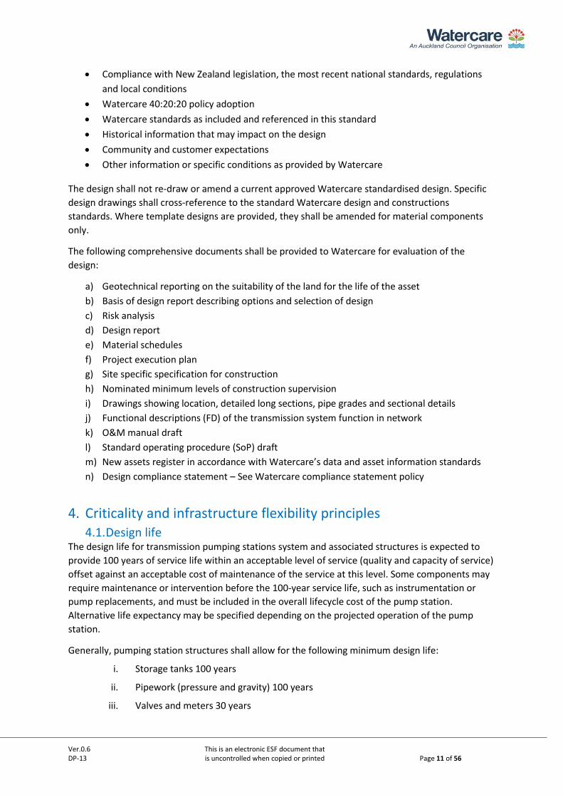
Generally, pumping station structures shall allow for the following minimum design life:
i. Storage tanks 100 years
ii. Pipework (pressure and gravity) 100 years
iii. Valves and meters 30 years
Ver.0.6 This is an electronic ESF document that DP-13 is uncontrolled when copied or printed Page 12 of 56
iv. Electrical equipment 25 years
v. SCADA and control 15 years
Note: Further information on life cycle cost and optimal point of replacement can be found in the
International Infrastructure Maintenance Manual (IIMM, 2015)
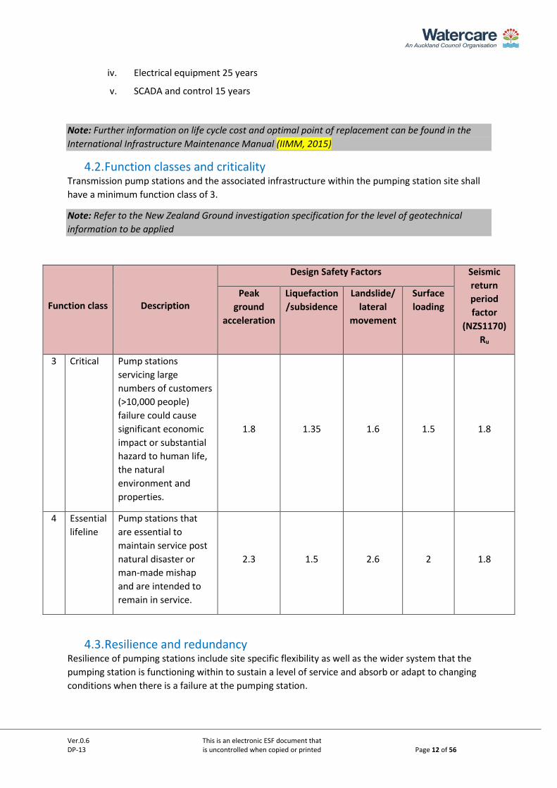
4.2. Function classes and criticality Transmission pump stations and the associated infrastructure within the pumping station site shall
have a minimum function class of 3.
Note: Refer to the New Zealand Ground investigation specification for the level of geotechnical
information to be applied
Function class Description
Design Safety Factors Seismic
return
period
factor
(NZS1170)
Ru
Peak
ground
acceleration
Liquefaction
/subsidence
Landslide/
lateral
movement
Surface
loading
3 Critical Pump stations
servicing large
numbers of customers
(>10,000 people)
failure could cause
significant economic
impact or substantial
hazard to human life,
the natural
environment and
properties.
1.8 1.35 1.6 1.5 1.8
4 Essential
lifeline
Pump stations that
are essential to
maintain service post
natural disaster or
man-made mishap
and are intended to
remain in service.
2.3 1.5 2.6 2 1.8
4.3. Resilience and redundancy Resilience of pumping stations include site specific flexibility as well as the wider system that the
pumping station is functioning within to sustain a level of service and absorb or adapt to changing
conditions when there is a failure at the pumping station.
Ver.0.6 This is an electronic ESF document that DP-13 is uncontrolled when copied or printed Page 13 of 56
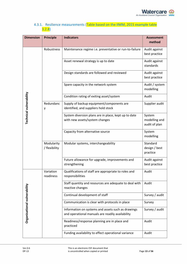
4.3.1. Resilience measurements {Table based on the IIMM, 2015 example table 3.2.8}
Dimension Principle Indicators Assessment
method
Tech
nic
al v
uln
erab
ility
Robustness Maintenance regime i.e. preventative or run-to-failure Audit against
best practice
Asset renewal strategy is up to date Audit against
standards
Design standards are followed and reviewed Audit against
best practice
Spare capacity in the network system Audit / system
modelling
Condition rating of exiting asset/system Audit
Redundanc
y
Supply of backup equipment/components are
identified, and suppliers hold stock
Supplier audit
System diversion plans are in place, kept up to date
with new assets/system changes
System
modelling and
audit of plan
Capacity from alternative source System
modelling
Modularity
/ flexibility
Modular systems, interchangeability Standard
design / best
practice
Future allowance for upgrade, improvements and
strengthening
Audit against
best practice
Org
anis
atio
nal
vu
lner
abili
ty
Variation
readiness
Qualifications of staff are appropriate to roles and
responsibilities
Audit
Staff quantity and resources are adequate to deal with
reactive changes
Audit
Continual development of staff Survey / audit
Communication is clear with protocols in place Survey
Information on systems and assets such as drawings
and operational manuals are readily availability
Survey / audit
Readiness/response planning are in place and
practiced
Audit
Funding availability to effect operational variance Audit
Ver.0.6 This is an electronic ESF document that DP-13 is uncontrolled when copied or printed Page 14 of 56
Dimension Principle Indicators Assessment
method
Insurance are up to date and with appropriate risk
cover
Audit
Leadership
/ culture
Decisive decision making Survey
Situational awareness Survey
System knowledge Survey
Innovative thinking Survey
External
partners
Ability to leverage on external knowledge Survey
Partnerships, design and service delivery
arrangements
Audit
Behavioural/communication barriers that could
restrict productive solutions
Survey
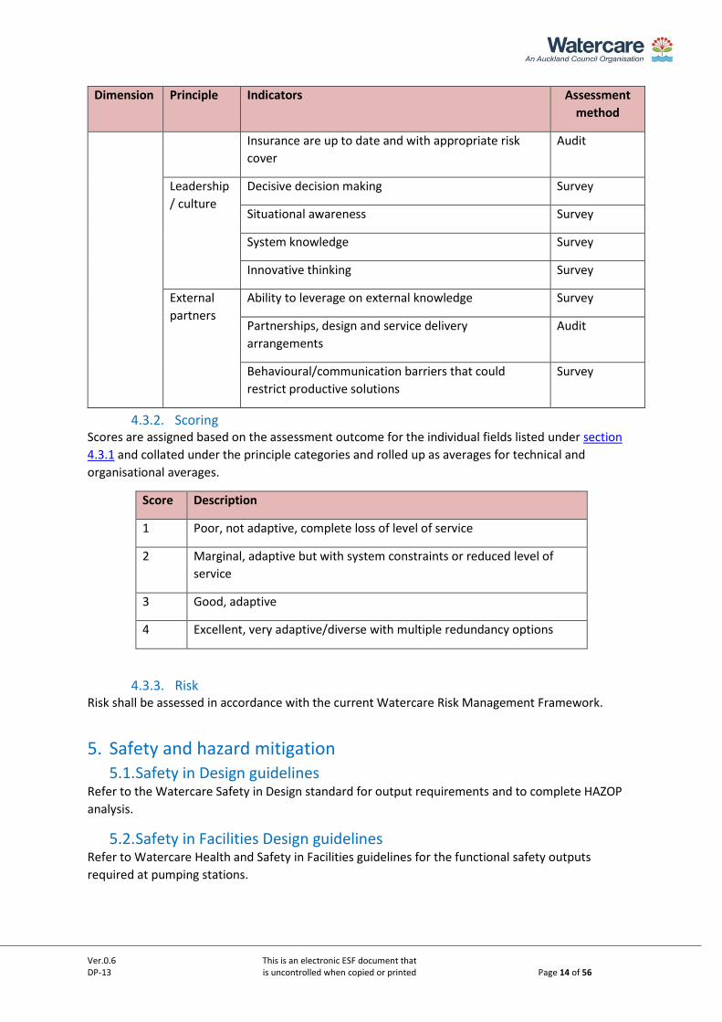
4.3.2. Scoring Scores are assigned based on the assessment outcome for the individual fields listed under section
4.3.1 and collated under the principle categories and rolled up as averages for technical and
organisational averages.
Score Description
1 Poor, not adaptive, complete loss of level of service
2 Marginal, adaptive but with system constraints or reduced level of
service
3 Good, adaptive
4 Excellent, very adaptive/diverse with multiple redundancy options
4.3.3. Risk Risk shall be assessed in accordance with the current Watercare Risk Management Framework.
5. Safety and hazard mitigation 5.1. Safety in Design guidelines
Refer to the Watercare Safety in Design standard for output requirements and to complete HAZOP
analysis.
5.2. Safety in Facilities Design guidelines Refer to Watercare Health and Safety in Facilities guidelines for the functional safety outputs
required at pumping stations.
Ver.0.6 This is an electronic ESF document that DP-13 is uncontrolled when copied or printed Page 15 of 56
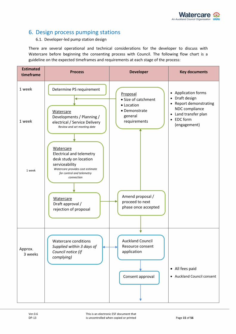
6. Design process pumping stations 6.1. Developer-led pump station design
There are several operational and technical considerations for the developer to discuss with
Watercare before beginning the consenting process with Council. The following flow chart is a
guideline on the expected timeframes and requirements at each stage of the process:
Estimated
timeframe Process Developer Key documents
1 week
1 week
1 week
• Application forms • Draft design • Report demonstrating
NDC compliance • Land transfer plan • EDC form
(engagement)
Approx. 3 weeks
• All fees paid
• Auckland Council consent
Determine PS requirement
Watercare Developments / Planning / electrical / Service Delivery
Review and set meeting date
Watercare Electrical and telemetry desk study on location serviceability Watercare provides cost estimate
for control and telemetry
connection
Auckland Council Resource consent application
Consent approval
Watercare conditions Supplied within 3 days of Council notice (if complying)
Watercare Draft approval / rejection of proposal
Proposal
• Size of catchment
• Location
• Demonstrate general requirements
• Demonstrate planning considerations & NDC compliance
Amend proposal / proceed to next phase once accepted
Ver.0.6 This is an electronic ESF document that DP-13 is uncontrolled when copied or printed Page 16 of 56
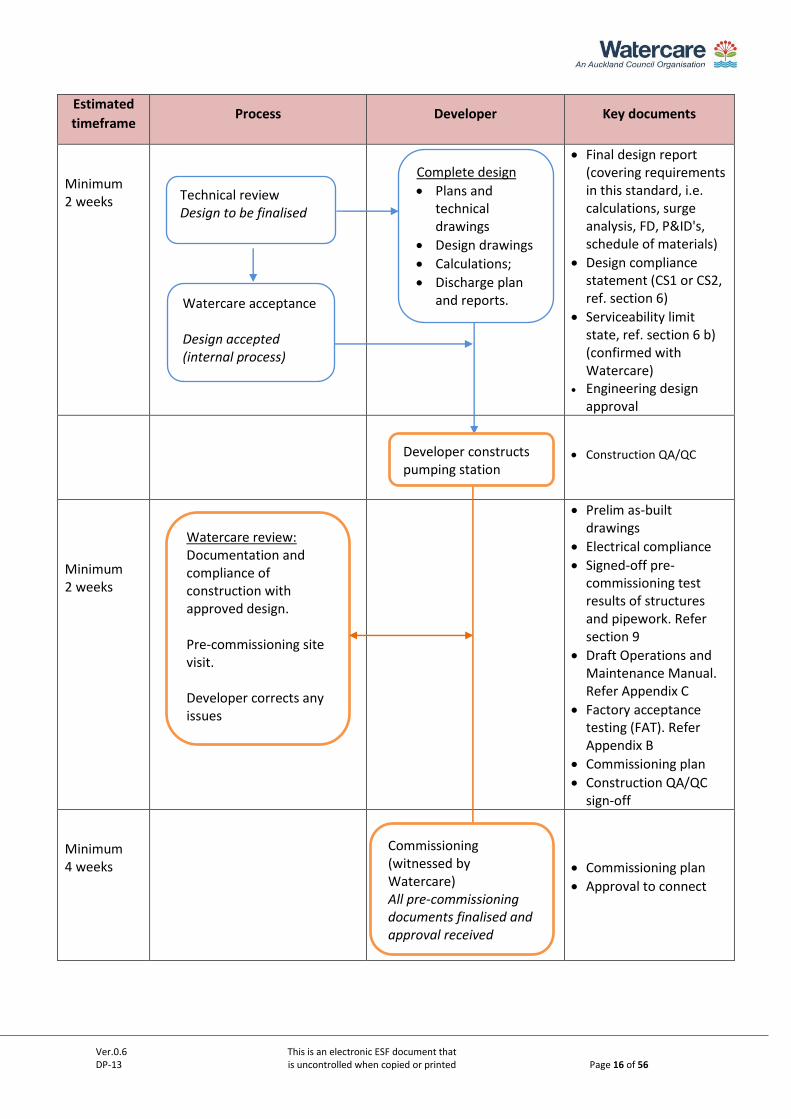
Estimated
timeframe Process Developer Key documents
Minimum 2 weeks
• Final design report (covering requirements in this standard, i.e. calculations, surge analysis, FD, P&ID's, schedule of materials)
• Design compliance statement (CS1 or CS2, ref. section 6)
• Serviceability limit state, ref. section 6 b) (confirmed with Watercare)
• Engineering design approval
• Construction QA/QC
Minimum 2 weeks
• Prelim as-built drawings
• Electrical compliance
• Signed-off pre-commissioning test results of structures and pipework. Refer section 9
• Draft Operations and Maintenance Manual. Refer Appendix C
• Factory acceptance testing (FAT). Refer Appendix B
• Commissioning plan
• Construction QA/QC sign-off
Minimum 4 weeks
• Commissioning plan
• Approval to connect
Commissioning (witnessed by Watercare) All pre-commissioning documents finalised and approval received
Complete design
• Plans and technical drawings
• Design drawings
• Calculations;
• Discharge plan and reports.
Technical review Design to be finalised
Watercare acceptance Design accepted (internal process)
Developer constructs pumping station
Watercare review: Documentation and compliance of construction with approved design. Pre-commissioning site visit. Developer corrects any issues
Ver.0.6 This is an electronic ESF document that DP-13 is uncontrolled when copied or printed Page 17 of 56
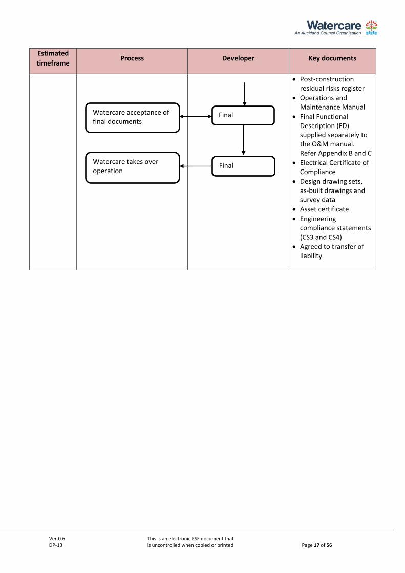
Estimated
timeframe Process Developer Key documents
• Post-construction residual risks register
• Operations and Maintenance Manual
• Final Functional Description (FD) supplied separately to the O&M manual. Refer Appendix B and C
• Electrical Certificate of Compliance
• Design drawing sets, as-built drawings and survey data
• Asset certificate
• Engineering compliance statements (CS3 and CS4)
• Agreed to transfer of liability
Watercare acceptance of final documents
Watercare takes over operation
Final documentation
Final documentation
Ver.0.6 This is an electronic ESF document that DP-13 is uncontrolled when copied or printed Page 18 of 56
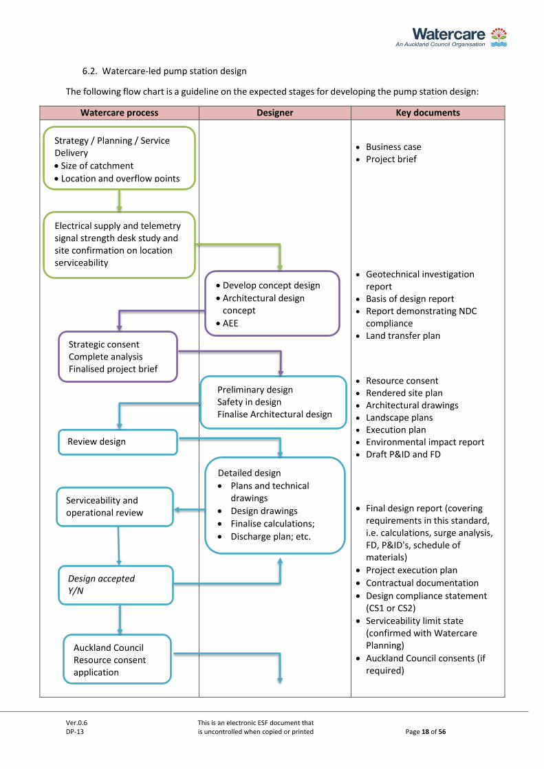
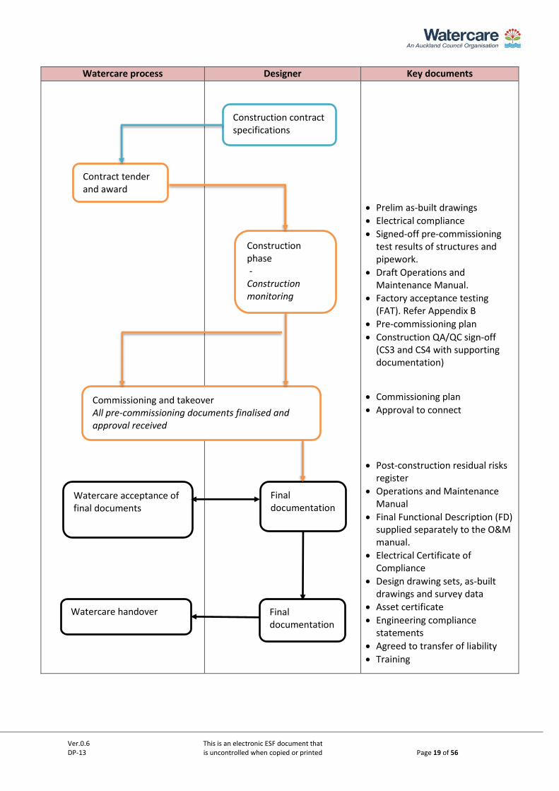
6.2. Watercare-led pump station design
The following flow chart is a guideline on the expected stages for developing the pump station design:
Watercare process Designer Key documents
• Business case • Project brief
• Geotechnical investigation report
• Basis of design report • Report demonstrating NDC
compliance • Land transfer plan
• Resource consent • Rendered site plan • Architectural drawings • Landscape plans • Execution plan • Environmental impact report • Draft P&ID and FD
• Final design report (covering requirements in this standard, i.e. calculations, surge analysis, FD, P&ID's, schedule of materials)
• Project execution plan
• Contractual documentation
• Design compliance statement (CS1 or CS2)
• Serviceability limit state (confirmed with Watercare Planning)
• Auckland Council consents (if required)
Strategy / Planning / Service Delivery
• Size of catchment
• Location and overflow points
Electrical supply and telemetry signal strength desk study and site confirmation on location serviceability
Review design
Preliminary design Safety in design Finalise Architectural design
Auckland Council Resource consent application Building consent application
Strategic consent Complete analysis Finalised project brief
• Develop concept design
• Architectural design concept
• AEE
Detailed design
• Plans and technical drawings
• Design drawings
• Finalise calculations;
• Discharge plan; etc.
Serviceability and operational review (Design to be finalised)
Design accepted Y/N
Ver.0.6 This is an electronic ESF document that DP-13 is uncontrolled when copied or printed Page 19 of 56
Watercare process Designer Key documents
• Prelim as-built drawings
• Electrical compliance
• Signed-off pre-commissioning test results of structures and pipework.
• Draft Operations and Maintenance Manual.
• Factory acceptance testing (FAT). Refer Appendix B
• Pre-commissioning plan
• Construction QA/QC sign-off (CS3 and CS4 with supporting documentation)
• Commissioning plan
• Approval to connect
• Post-construction residual risks register
• Operations and Maintenance Manual
• Final Functional Description (FD) supplied separately to the O&M manual.
• Electrical Certificate of Compliance
• Design drawing sets, as-built drawings and survey data
• Asset certificate
• Engineering compliance statements
• Agreed to transfer of liability
• Training
Construction contract specifications
Contract tender and award
Construction phase - Construction monitoring
Commissioning and takeover All pre-commissioning documents finalised and approval received
Watercare acceptance of final documents
Watercare handover
Final documentation
Final documentation
Ver.0.6 This is an electronic ESF document that DP-13 is uncontrolled when copied or printed Page 20 of 56
7. Pumping station planning considerations The feasibility study shall consider technical, environmental and financial criteria over the entire
design life of the system.
When planning and designing for a pumping station; consideration shall be given to pumping station
placement including:
• Future expansion / upgrades that will allow the existing infrastructure to accommodate overall increase in the capacity of the pumping station and other staged infrastructure
• Running costs, life-cycle and ongoing maintenance costs
• The impact on existing pumping stations requires a full system integrated design
• Septicity within the pump station and connected pipework, odour issues and corrosion of equipment and pipes
• Environmental and health and safety risks
• Dry-weather storage capacity
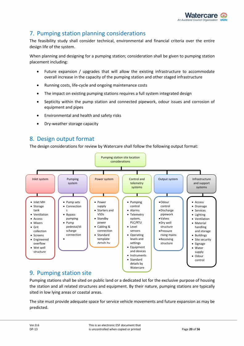
8. Design output format The design considerations for review by Watercare shall follow the following output format:
9. Pumping station site Pumping stations shall be sited on public land or a dedicated lot for the exclusive purpose of housing
the station and all related structures and equipment. By their nature, pumping stations are typically
sited in low lying areas or coastal areas.
The site must provide adequate space for service vehicle movements and future expansion as may be
predicted.
Pumping station site location considerations
Pumping system
Power system Control and telemetry systems
Output system Infrastructure and support
systems
Inlet system
• Inlet MH
• Storage tank
• Ventilation
• Access
• Mixers
• Grit collection
• Screens
• Engineered overflow
• Wet well structure
• Pump sets
• Connections
• Bypass pumping
• Pump pedestal/discharge connection
•
• Power supply
• Starters and VSDs
• Standby power
• Cabling & connection
• Standard template details by
• Pumping control
• Alarms
• Telemetry system, PLC/RTU
• Level sensors
• Operating levels and settings
• Equipment and devices
• Instruments
• Standard details by Watercare
•Odour control
•Discharge pipework
•Valves
•Dry well structure
•Pressure rising mains
•Receiving structure
• Access
• Drainage
• Services
• Lighting
• Ventilation
• Material handling and storage
• Buildings
• Site security
• Signage
• Water supply
• Odour control
Ver.0.6 This is an electronic ESF document that DP-13 is uncontrolled when copied or printed Page 21 of 56
A reverse sensitivity (or non-sensitivity) covenant must be placed on the titles to be issued for any
adjoining lots within a minimum of 20 metres from the pumping station lot boundary. Factors that
determine the covenant distance to be greater than 20 metres shall be based on the nature of the
pump station operations, the pump station size and its location.
Land developers must notify all prospective purchasers’ of the lots that are adjacent to the pumping
station of its location and associated structures. Examples of such plans could be the development
plan (scheme plan) that the developer lodges with council under s223.
The pumping station general site layout shall have:
a) A level aspect within the boundaries of the pumping station.
b) 24hr all-weather vehicle access, adequate parking and adequate manoeuvrability and hard stand areas to access all components for maintenance and replacement.
c) Odour control system(s) shall be required at the pumping station and have a minimum of 12m horizontal clearance from the adjacent property boundaries.
d) A minimum ADWF storage capacity to satisfy the conditions of the NDC (see Appendix A) and an engineered overflow.
Note: Watercare requires a typical ADWF storage capacity of 4 hours, or best practicable option (BPO) to meet the requirements of the NDC. Watercare’s assessment of suitable storage may be influenced by operational resilience, the upstream connecting network and the catchment interconnectivity and may therefore require the capacity to be increased.
e) Dedicated underground mains power supply.
f) A dedicated control room or cabinet to house electrical equipment as specified in the Watercare electrical and control standards. Control rooms and cabinets shall be a minimum of 500mm above the 0.5%AEP flood level.
g) The infrastructure must be designed to remain in service under a 0.5%AEP event.
h) Building doors, switchboards, control cabinets and chamber cover-plates are to be provided with adequate clearances for maintenance access.
i) Electrical connection facilities for the provision of a temporary generator.
j) Dedicated utility service ducting.
k) The pump station inlet structure.
l) Wet well configuration with associated outlet valves and metering.
m) Chemical storage and handling facility if required
n) Landscaping and planting as required by consent conditions or as otherwise specified by Watercare during the design review. Refer to Watercare architectural design guidelines.
9.1. Site ground conditions Ground investigations shall be completed in accordance with the New Zealand Ground investigation
specification, 2017 (http://www.nzgs.org/library/nz-ground-investigation-specification).
All data collected shall be uploaded to the New Zealand Geotechnical Database in AGS4 format at: https://www.nzgd.org.nz
Ver.0.6 This is an electronic ESF document that DP-13 is uncontrolled when copied or printed Page 22 of 56
Contaminated sites should be avoided. Where a contaminated site has been confirmed, written
approval to proceed shall be obtained from the Auckland Council. The following issues shall be
addressed in the request for approval:
• The nature of the contamination;
• Compliance with statutory requirements;
• Options to de-contaminate the area;
• Selection of pipeline materials to achieve the required life expectancy of the wastewater
main;
• Safety of construction and maintenance personnel; and
Any contaminants in the soil, including topsoil on the site, shall be at the lesser levels of the health-
based or environmental related protection values as described below:
• Health based protection values:
NES Soil contaminant standards (SCS) for residential land use (no produce, if applicable) as
derived in accordance with Ministry for the Environment Methodology for Deriving
Standards for Contaminants in Soil to Protect Human Health (Chapter 7). In the absence of
a derived NES Soil SCS, then a standard following the hierarchy outlined in the Ministry for
the Environment, Contaminated Land Management Guidelines No 2 shall be adopted.
• Environmental related protection values:
Auckland Council Air Land and Water (ALW) Plan criteria for discharges as described in
Rules 5.5.41.
• No asbestos containing material or volatile organic compounds in site soils.
No free (or separate) phase liquid contaminants and groundwater contaminant concentrations,
except for volatile organic compounds, which must be below the Australian and New Zealand
Guidelines for Fresh and Marine Water Quality at the level of protection for 80% of freshwater
species. Concentrations of volatile organic compounds shall be below typical laboratory screening
detection limits (0.5 mg/L or lower).
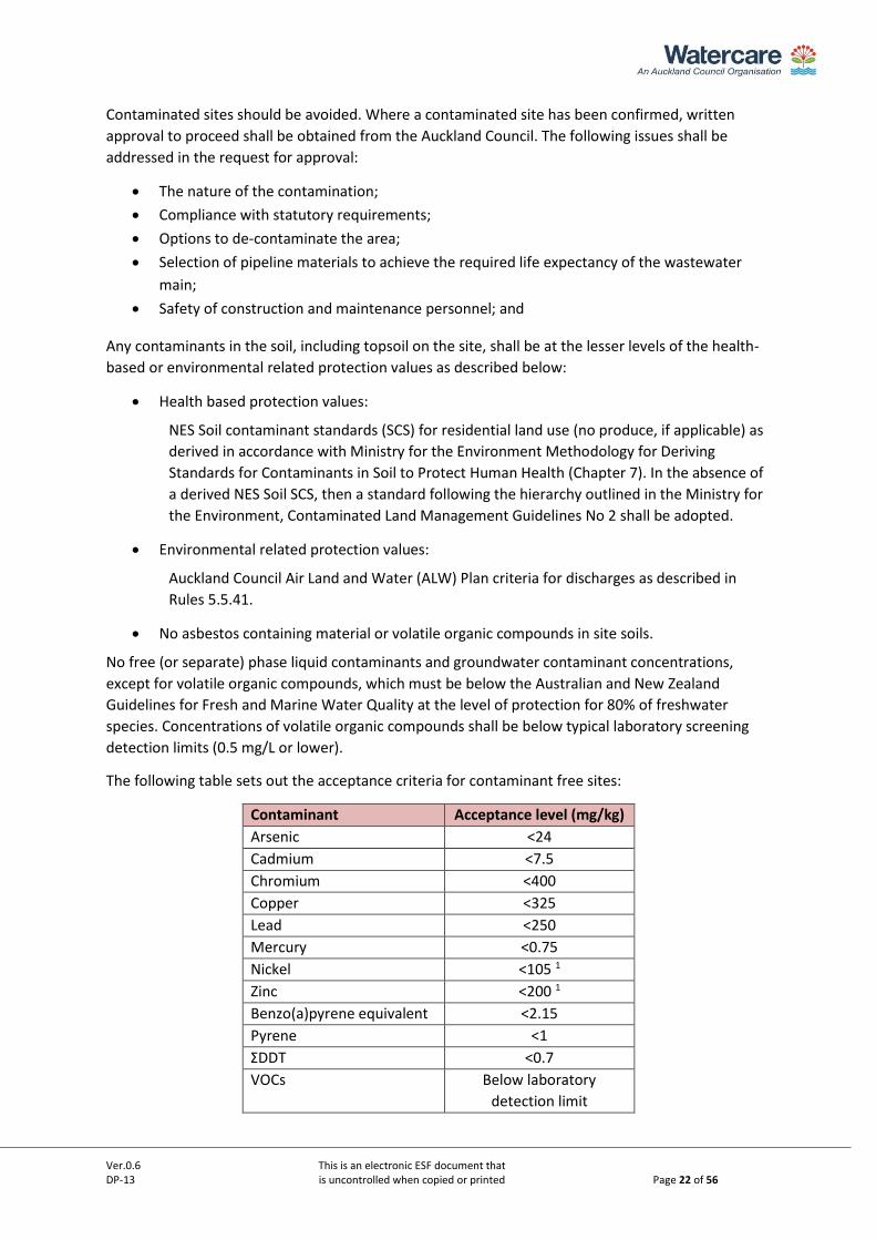
The following table sets out the acceptance criteria for contaminant free sites:
Contaminant Acceptance level (mg/kg)
Arsenic <24
Cadmium <7.5
Chromium <400
Copper <325
Lead <250
Mercury <0.75
Nickel <105 1
Zinc <200 1
Benzo(a)pyrene equivalent <2.15
Pyrene <1
ΣDDT <0.7
VOCs Below laboratory
detection limit
Ver.0.6 This is an electronic ESF document that DP-13 is uncontrolled when copied or printed Page 23 of 56
1 Can use upper limit background concentration in Auckland region (i.e. 320 for Nickel and 1160 for Zinc) if the soil is
volcanic source
A site investigation including soil sampling and testing must be undertaken and a report submitted
to Watercare in accordance with the requirements of the Ministry for the Environment, 2011,
Contaminated Land Management Guidelines No. 1 - Reporting on Contaminated Sites in New
Zealand. Testing shall be conducted by a NATA/IANZ accredited laboratory.
Soil testing data is required at the position for the proposed pumping station. Depending on the size
of the proposed site additional soil testing at more than one location may be required if a single sample
is not considered representative of the site.
10. General design considerations The general design considerations include:
a) Determine pumping system demands for transmission pump stations in accordance with DP-
07 Design principles for transmission water and wastewater pipeline design, Part B, and for
network pump station refer to COP-02.
b) Determine the station lifting height requirements, flow losses through pipework and fittings to calculate the total head.
c) Develop the system curve that considers:
• The flow velocity at initial flows and ultimate state flows including any staging.
• Friction losses, minor losses and static head.
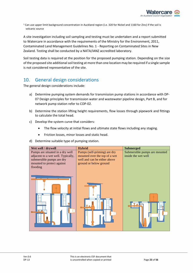
d) Determine suitable type of pumping station.
Wet well / drywell Hybrid Submerged Pumps are situated in a dry well
adjacent to a wet well. Typically,
submersible pumps are dry
mounted to protect against
flooding
Pumps (self-priming) are dry
mounted over the top of a wet
well and can be either above
ground or below ground
Submersible pumps are mounted
inside the wet well
Ver.0.6 This is an electronic ESF document that DP-13 is uncontrolled when copied or printed Page 24 of 56
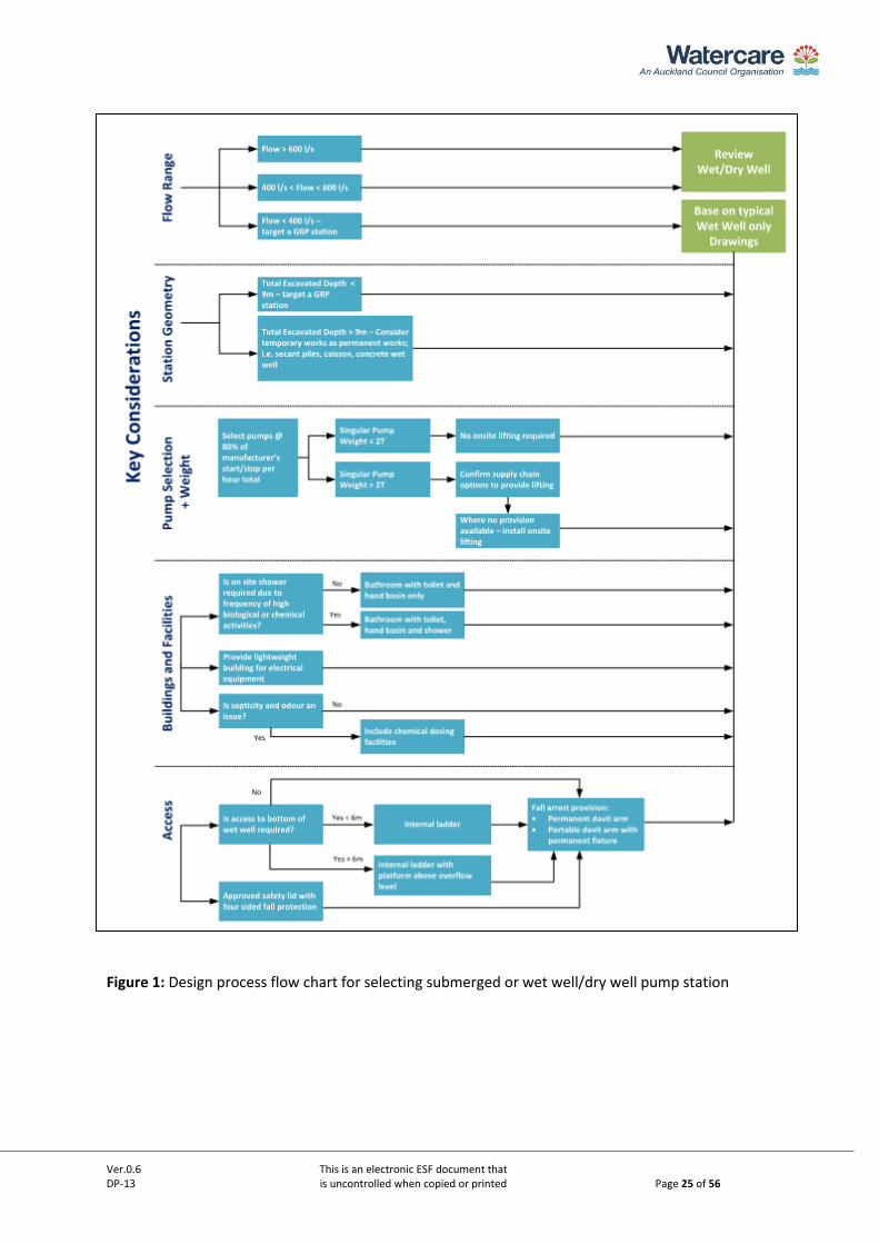
The below table and flow chart in Figure 1 provides high-level guidance on typical
application of the three major layout types. The preferred pumping arrangement is a wet
well only submersible pumping station to align with Watercare’s 40/20/20 goals.
The pumping station arrangement shall ultimately be determined by pump size, lifting
considerations and any special considerations to be determined in conjunction with
Watercare at the commencement of the project (for example site location and proximity to
public).
The selection of pumping arrangement shall generally follow the following flow chart, noting
that the flow chart does not include hybrid type pumping stations, which may be suitable in
the following scenarios:
• <200l/s flow
• <40m total dynamic head
• <6m suction side lift
Note: When larger pumps are considered a suitable material handling solution must be provided.
Consideration must be given to the above ground footprint, safety, and storage of any on-site
devices and the site layout equipment to be brought on site. The diagram shows typical
selection criteria.
Please refer to the below flow chart to help optimise the pumpstation type selection:
Ver.0.6 This is an electronic ESF document that DP-13 is uncontrolled when copied or printed Page 25 of 56
Figure 1: Design process flow chart for selecting submerged or wet well/dry well pump station
Ver.0.6 This is an electronic ESF document that DP-13 is uncontrolled when copied or printed Page 26 of 56
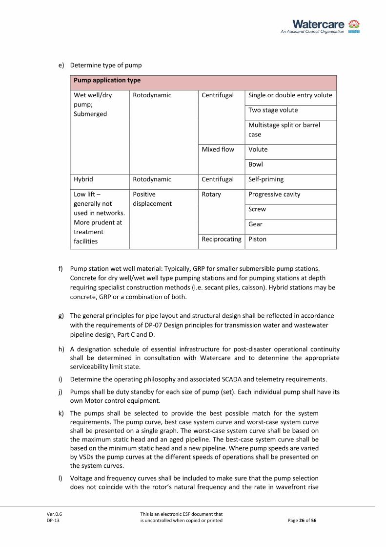
e) Determine type of pump
Pump application type
Wet well/dry
pump;
Submerged
Rotodynamic Centrifugal Single or double entry volute
Two stage volute
Multistage split or barrel
case
Mixed flow Volute
Bowl
Hybrid Rotodynamic Centrifugal Self-priming
Low lift –
generally not
used in networks.
More prudent at
treatment
facilities
Positive
displacement
Rotary Progressive cavity
Screw
Gear
Reciprocating Piston
f) Pump station wet well material: Typically, GRP for smaller submersible pump stations.
Concrete for dry well/wet well type pumping stations and for pumping stations at depth
requiring specialist construction methods (i.e. secant piles, caisson). Hybrid stations may be
concrete, GRP or a combination of both.
g) The general principles for pipe layout and structural design shall be reflected in accordance
with the requirements of DP-07 Design principles for transmission water and wastewater
pipeline design, Part C and D.
h) A designation schedule of essential infrastructure for post-disaster operational continuity shall be determined in consultation with Watercare and to determine the appropriate serviceability limit state.
i) Determine the operating philosophy and associated SCADA and telemetry requirements.
j) Pumps shall be duty standby for each size of pump (set). Each individual pump shall have its own Motor control equipment.
k) The pumps shall be selected to provide the best possible match for the system requirements. The pump curve, best case system curve and worst-case system curve shall be presented on a single graph. The worst-case system curve shall be based on the maximum static head and an aged pipeline. The best-case system curve shall be based on the minimum static head and a new pipeline. Where pump speeds are varied by VSDs the pump curves at the different speeds of operations shall be presented on the system curves.
l) Voltage and frequency curves shall be included to make sure that the pump selection does not coincide with the rotor’s natural frequency and the rate in wavefront rise
Ver.0.6 This is an electronic ESF document that DP-13 is uncontrolled when copied or printed Page 27 of 56
does not cause electromagnetic disturbances.
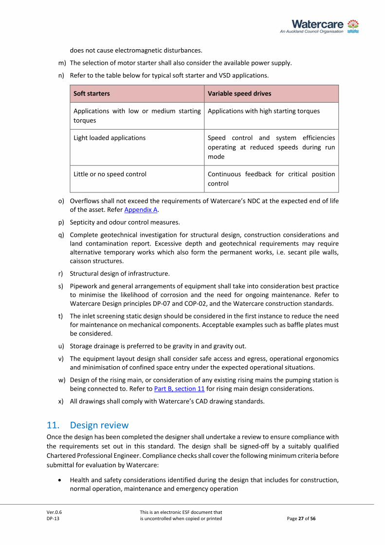
m) The selection of motor starter shall also consider the available power supply.
n) Refer to the table below for typical soft starter and VSD applications.
Soft starters Variable speed drives
Applications with low or medium starting
torques
Applications with high starting torques
Light loaded applications Speed control and system efficiencies
operating at reduced speeds during run
mode
Little or no speed control Continuous feedback for critical position
control
o) Overflows shall not exceed the requirements of Watercare’s NDC at the expected end of life of the asset. Refer Appendix A.
p) Septicity and odour control measures.
q) Complete geotechnical investigation for structural design, construction considerations and land contamination report. Excessive depth and geotechnical requirements may require alternative temporary works which also form the permanent works, i.e. secant pile walls, caisson structures.
r) Structural design of infrastructure.
s) Pipework and general arrangements of equipment shall take into consideration best practice to minimise the likelihood of corrosion and the need for ongoing maintenance. Refer to Watercare Design principles DP-07 and COP-02, and the Watercare construction standards.
t) The inlet screening static design should be considered in the first instance to reduce the need for maintenance on mechanical components. Acceptable examples such as baffle plates must be considered.
u) Storage drainage is preferred to be gravity in and gravity out.
v) The equipment layout design shall consider safe access and egress, operational ergonomics and minimisation of confined space entry under the expected operational situations.
w) Design of the rising main, or consideration of any existing rising mains the pumping station is being connected to. Refer to Part B, section 11 for rising main design considerations.
x) All drawings shall comply with Watercare’s CAD drawing standards.
11. Design review Once the design has been completed the designer shall undertake a review to ensure compliance with
the requirements set out in this standard. The design shall be signed-off by a suitably qualified
Chartered Professional Engineer. Compliance checks shall cover the following minimum criteria before
submittal for evaluation by Watercare:
• Health and safety considerations identified during the design that includes for construction, normal operation, maintenance and emergency operation
Ver.0.6 This is an electronic ESF document that DP-13 is uncontrolled when copied or printed Page 28 of 56
• Community and environmental impact assessment
• System components, layout and configuration meet this standard and are in accordance with the typical pumping station standard details in the standard drawings
• Pump selection
• Plans indicating layout covering pipe size, grade, material types, transfer points and long sections
• Details of air release/vacuum and scour points
• Route selection meets concept/planning design
• Easements as appropriate
• Geotechnical data and considerations are taken into account during design
• Provisions made for future extension as appropriate, including upgrade staging and triggers
• Life cycle cost
• Compliance with referenced standards
12. Construction Each section, the inlet structure, the wet well with pumps and the outlet system shall be constructed
but not connected until individually tested, unless suitable isolation is available to complete individual
tests before testing and commissioning the system (refer to section 14 on commissioning).
Construction practices for components shall comply with the following Watercare standards:
a) General civil construction standard
b) General mechanical construction standard
c) General electrical construction standard
d) Material supply standard
13. Pumping station asset data Pumping station data shall be captured in accordance with Watercare Data and Asset Information
standard and the Watercare CAD manual and as specified in the project specific Exchange of
Information Requirements (EIR).
Note: As a minimum, redline mark-ups will be accepted for commissioning in anticipation of the final
asbuilts being provided at handover.
14. Testing and Handover 14.1. Commissioning
This section shall be read with Watercare’s Code of Practice for Commissioning.
All pre-testing and quality assurance checks shall be completed before commencing with
commissioning.
Once the individual sections have been tested, the final connections are made ready for
commissioning of the pumps. A suitably qualified Watercare representative for the respective
Ver.0.6 This is an electronic ESF document that DP-13 is uncontrolled when copied or printed Page 29 of 56
engineering disciplines shall witness the commissioning in conjunction with the third-party
professional(s) that is responsible for the commissioning works.
Commissioning work shall not progress unless the following documentation has been provided and
has been accepted to proceed:
• Preliminary as-built drawings
• Electrical compliance
• Signed-off pre-commissioning test results of structures and pipework
• Draft Functional Description
• Process and instrumentation diagrams (P&ID)
• Draft Operations and Maintenance (O&M) Manual
• Factory acceptance testing (FAT) completed, see Watercare Code of Practice for Commissioning (COP-03)
• Redline mark-up as-built drawings
• Training
• Commissioning plan
• Applicable construction quality control signed off
The commissioning plan shall include, but is not limited to:
• HAZOP study
• Testing of all control system inputs and outputs (I/O’s), see Watercare Code of Practice for Commissioning (COP-03)
• Wet well level sensors and height adjustment
• Alarm status
• Pump control units
• Remote control and data transmission (RTU and PLC checks)
• Data logging and analysis
• Pump flow rates and rising main performance
• Noise and vibration level conforming during operation
• Odour control testing (following operational time) where required
Following the commissioning of the pumping station, any odour control systems installed shall be
tested. A minimum of 4 weeks of operation shall have passed from the date of commissioning before
testing H2S levels at all venting locations. Any faults shall be corrected and retested after a further 4
weeks of bio-acclimatisation. H2S concentration shall be measured under still atmospheric conditions.
Any non-conformance with this standard shall be corrected and re-tested.
14.2. Rejection of materials or products All materials specified shall be accepted or standardised equipment as appropriate. Where products
are required to be sourced that is not listed on any of these materials lists, prior approval by Watercare
is required.
Ver.0.6 This is an electronic ESF document that DP-13 is uncontrolled when copied or printed Page 30 of 56
Materials supplied shall comply with the nominated standards and the minimum certification criteria
provided as part of the handover process. Where substitutions of any materials or products are
deemed necessary during the construction of the pumping station, approval in writing from both
Watercare and the pumping station designer is required.
Materials not accepted by Watercare shall be replaced at no additional cost to Watercare.
14.3. Handover documents Watercare shall take over the pumping station when all of the below documentation is finalised and
supplied and in accordance with the Watercare Code of practice for commissioning (CoP-04) and the
Data and Asset Information Standard (AI) documents:
a) Post-construction residual risks register
b) Signed construction quality control sheets
c) Operations and Maintenance Manual, see Watercare’s Data and Asset Information standard
d) Final Functional Description (FD) (supplied electronically and separate to the O&M manual), see Watercare’s Data and Asset Information standard
e) Electrical Certificate of Compliance
f) Provisional takeover certificate (following commissioning)
g) Design drawing sets, as-built drawings, models and survey data
h) New assets register including for associated linear assets in accordance with Watercare’s Data and Asset Information standard
i) Final handover certificate on completion of all as-built information and any outstanding retention items
j) Engineering compliance statements for design, construction and construction monitoring
Where materials have not been supplied by Watercare, all product and material warranties and guarantees shall be transferred to Watercare.
Ver.0.6 This is an electronic ESF document that DP-13 is uncontrolled when copied or printed Page 31 of 56
PART B – TYPICAL PUMP STATION DESIGN PARAMETERS
Ver.0.6 This is an electronic ESF document that DP-13 is uncontrolled when copied or printed Page 32 of 56
1. Material selection All materials shall comply with Watercare’s material supply standards. The following specific
considerations shall be considered at key infrastructure:
1.1. Wet well a) The wet well design shall consider high corrosion and sulphide attack on concrete surfaces.
Concrete wet wells shall be constructed from either concrete with resistance to corrosive
attack i.e. calcium aluminate, polymer concrete and be protected with a suitably painting
system, or alternative materials such as polyethylene and GRP.
b) Where painted coatings are used the designer must complete the product schedule in the
Material Supply standard and provide this to the coating supplier to support the coating
selection. The selected coating system must have a life expectancy without maintenance
more than 50 years.
1.2. Inlet and outlet pipework a) Inlet pipework to the wet well shall be selected to the appropriate design class from the
materials listed in the Watercare Material Supply standard.
b) Pump intake pipework from the wet well to the pump intake shall be internally and
externally corrosion protection to withstand high H2S levels and shall have a high abrasion
resistance rating in excess of 25 years. Refer to the Watercare Material supply standard for
the suitable epoxy coating system.
c) Inlet and outlet pipework material must be selected for longevity, corrosion and erosion
preventions properties, but also for ease of maintainability. Typical selection is ELS (epoxy
lined carbon steel) or stainless-steel pipe.
1.3. Pipe Material a) Pipe material shall be supplied in compliance with the applicable Watercare material
standard.
b) The minimum pipe pressure rating shall be PN16 and any other component valve or fitting
shall have a minimum pressure rating of PN16.
c) The maximum pressure design shall consider pipe and fittings to be pressure de-rated based
on the material maximum cyclic pressure range (MCPR).
d) The maximum operating pressure shall be less than the MCPR.
1.4. Valves a) Valves and componentry shall be suitable for use with wastewater and the installed
environment.
b) Valve installations shall be constructed with adequate support that will allow the valves to
be freestanding, should any other component be removed.
c) The pipework design shall allow for removal of valves and where required dismantling joints
shall be used.
d) Isolation and non-return valves shall be the same diameter as the pipework they are being
installed on.
e) Isolation valves shall be operable from ground level where buried unless inside the dry well.
1.5. Non-return valves a) Non-return valves shall be of the swing check type with a rubberised steel disc, or a pump
control valve and as accepted by Watercare. The selection must take into consideration any
pumping surge.
Ver.0.6 This is an electronic ESF document that DP-13 is uncontrolled when copied or printed Page 33 of 56
1.6. Isolation valves a) Isolation valves shall be of the metal seated gate type. Isolation valves shall be installed on
each pump intake (for wet well/dry well pumps) and on the pump discharge downstream of
the non-return valves.
1.7. Air release valves a) Air release valves where installed on the rising main, shall be double acting and as accepted
by Watercare.
b) The air valves shall be in an accessible chamber that is vented. Air valves must be designed
for connection of a suitable air treatment facility and where required and fitted with a vent
stack that ensure no noticeable odour at the nearest property boundary. H2S shall be less
than 0.004ppm measured at the filter outlet.
2. Receiving structure (discharge manhole) a) The rising main shall discharge into a fit-for-purpose manhole structure that will dissipate
the energy of the rising main prior to transition into the gravity system.
b) The rising main shall discharge into the discharge manhole on a rising gradient. The rise into
the receiving structure shall be a minimum of 3m long. No other connections shall be made
into the discharge manhole.
c) The fall through the chamber between the top of the rising main pipe entry and the outlet
pipe shall be a minimum of 150mm.
d) The rising main and manhole outlet shall not be more than 30 degrees out of alignment.
Where drop structures are considered, a specific design should be undertaken.
e) Refer to Part D, section 10 for odour control options.
3. Grit Collection and Screens 1. In areas where grit collection or pre-treatment by screening is required, the system shall be
incorporated into or upstream of the inlet structure.
2. Penstocks or knife-gate valves shall be installed upstream of screens to allow isolation for
cleaning.
4. Pumping Station Inlet System 4.1. General
The design of the inlet structure shall have the following functions and requirements:
a) Collect all wastewater inflow into the pumping station.
b) Provide access or location for grit collection when required.
c) Be able to facilitate bypass pumping and selective isolation by penstock or similar suitable valve for maintenance.
d) Isolation valves shall be accessible for operation without the need for confined space access.
e) The inlet structure shall be configured to minimise incoming flow turbulence and prevent build-up of debris.
Ver.0.6 This is an electronic ESF document that DP-13 is uncontrolled when copied or printed Page 34 of 56
4.2. Inlet structure material preference a) The inlet structure shall be constructed from either concrete with resistance to corrosive
attack i.e. calcium aluminate, polymer concrete; be protected with a suitable painting
system; or be constructed from corrosion resistant material (i.e. GRP or PE). The designer
must complete the project schedule in the Material Supply standard and provide this to the
coating supplier to support the coating selection.
5. Wet well inlet The inlet between the inlet structure and wet well shall have the following features:
a) An inlet arrangement to minimise turbulence that could create H2S gas generation or poor pump performance and be situated as far as possible away from the pump intakes.
b) Discharge from the inlet structure will not flow directly onto a pump intake and be arranged such that the inflow into the wet well during high flow does not cause eddies (e.g. deflector or flow diffuser).
c) The inlet height shall not exceed 1.5m above the bottom operating water level to limit air entrapment and shall be graded towards the pump takes.
6. Wet well a) Structural design shall be to the selected function class. Refer to Part A, section 4.2.
b) The wet well level shall be monitored.
c) The base of the wet well shall be shaped and angled to prevent septicity and “dead zones” where solids can accumulate.
d) Allow adequate clearance from well sides and base to pump intakes in accordance with the pump manufacturer’s installation recommendations.
e) Ventilation shall be installed for all pumping stations at a level of at least 150mm above the well overflow level and 150mm below the well lid. The location and angle of the outlet of the duct will allow condensation to freely drop back into the well and be at the furthest point away from the inlet. Ventilation shall not be directed through the dry well or control room
f) An air treatment facility shall be installed at ground level. The ventilation system shall be designed to provide an appropriate ventilation velocity. Refer to Part D, section 10 for biofilter and carbon filter requirements. The design of the air treatment facility shall be site specific with
consideration to frequency of operation and replacement of filter media or chemicals.
g) Watercare standard design details shall be used for all lids, see drawing set DW05. Hatches shall comply with AS3996 to the appropriate class.
h) All access hatches shall be fitted with a hinged safety grille underneath the lockable access hatch. Safety grilles shall be tested to comply with AS3996 class A. Perimeter protection shall be provided on all four sides of the opening for fall protection.
6.1. Size of the wet well and levels The size of the wet well shall be determined by the following criteria.
a) The maximum retention time of wastewater during normal operation shall be 2 hours.
Ver.0.6 This is an electronic ESF document that DP-13 is uncontrolled when copied or printed Page 35 of 56
b) The wet well operating range (pump start to the minimum level above pump intakes) to prevent settling (typically 1m) and limit the pump starts to no more than 80% of the pump manufacturer’s maximum recommended starts per hour.
c) The maximum top water level shall be determined by examination of the upstream surcharge level. The maximum top level is only reached when the duty pump is unable to manage the inflow. Standby pumps are switched on at this level and may be staged for more than one standby pump.
d) The overflow level is set above the maximum top water level. The overflow alarm is activated at this level and all pumps running. See section 7 below for overflow arrangements.
e) The volume between pump start and pump stop shall be determined by pump capacity and be set to limit the frequency of pump starts. The pump start level shall pump intake minimum submergence to avoid vortices from forming in the wet well and provide the required NPSH
f) A hydraulic model shall be carried out to test the wet well design for uniform hydraulic distribution over the pump station operational range.
g) Internal access platforms to support entry to the wet well via ladders shall be located above the overflow level.
7. Pump station overflow The pump station overflow may be placed at the pump station or another nearby suitable location in
a purpose-built overflow manhole and include the following requirements:
a) The overflow shall be from the inlet structure.
b) The overflow location and level (impact on well storage size) shall be determined through an
environmental impact assessment with resource consent requirements and conditions in
mind
c) The overflow shall be into an overflow structure with connecting outfall that must be
accessible by a sucker truck.
d) The outlet from the overflow manhole shall be fitted with a stainless-steel baffle plate or
concrete where maintainable, to prevent scum discharge to the environment.
e) Drainage fall shall be away from the overflow manhole to allow draining back to the wet well
f) The outfall outlet shall be fitted with a non-return flap valve or similar.
g) The outfall shall be constructed with a wing wall and fitted with a stainless-steel grid. The
stainless-steel grid bar spacing shall be minimum 25mm to prevent blockages and not be
more than 100mm spacing. It must be designed to allow ready access for maintenance and
cleaning.
h) The specific design shall take into consideration energy dissipation and erosion control in the
receiving environment.
8. Wash/pump-out a) The scour valve locations shall be at the lowest points of the pipeline.
b) The number of scour valve locations shall be decided based on the length of the rising main
at adequate intervals to reduce drain down time for repair and maintenance.
c) Scour valve locations shall provide access for sucker trucks
d) The chamber shall be provided with a sump for installation of a portable drainage pump
Ver.0.6 This is an electronic ESF document that DP-13 is uncontrolled when copied or printed Page 36 of 56
9. Ventilation a) All components, fixings, supports, etc. shall be fabricated from corrosion resistant materials.
Preferred materials include stainless steel 316, PVC and GRP as applicable.
b) Galvanised steel is not acceptable.
c) Refer to Part D, section 10 for air quality treatment.
10. Pumping System 10.1. Hydraulic design
The hydraulic design shall be determined by the following parameters:
a) Invert level of the incoming wastewater.
b) Pumping station capacity (initial and ultimate capacity).
c) Internal diameter, length, route and materials of the rising main, including surge and fatigue analysis, see section 10.2 below.
d) In deriving the system curve the static head shall be based on pump duty start level at 150mm below the invert level of the incoming wastewater pipe.
e) Levels and profile of the rising main and discharge point. See section 11 below.
f) High points - to account for possible characteristics controlled by intermediate highpoints along the rising main.
g) Combined detention times for wet well and rising main(s) not exceeding 8 hours where possible for initial flows.
h) Shear velocity to prevent slime build-up in rising mains that will increase flow resistance over time
i) Capacity restriction in the receiving sewer
10.2. Pump selection
a) Common pump arrangements are vertical centrifugal pumps in a dry well or wet well with direct motor drive, or self-priming surface mounted pumps. Submersible pumps in dry wells should be considered for transmission applications where surface and dry well flooding can occur. Dry-mounted submersible pumps require consideration of the specific cooling method. Wet mounted pumps are to be glycol cooled.
b) Pump with motor decibel rating shall be less than 80dB.
c) Pump selection shall be within ±5% of the pump best efficiency point (BEP) at the peak dry weather flow rate (PDWF) which equates to half the peak wet weather flow rate (PWWF) or the most frequent flow rate that the pump station will be operating at. The design flow capacity of a pump station is generally sized to match the PWWF. The pumps shall, however, be selected to also operate withing the acceptable operating range (AOR) of the pumps at the PWWF.
d) Where possible the minimum overall pump efficiency shall not be less than 70%. (depending on the pump and impeller type). Lower efficiency may be considered in the following exceptional circumstances:
i. There is no other pump available for the specified duties or
Ver.0.6 This is an electronic ESF document that DP-13 is uncontrolled when copied or printed Page 37 of 56
ii. The anticipation of excessive impeller clogging, and the associated maintenance outweighs the energy saving costs of selecting a more efficient impeller type or pump selection.
e) Pump head curves with very flat head flow characteristics can make the pump difficult to control due to small changes in system resistance that can create large changes in flow rate (i.e. ‘hunting'). The use of variable speed drives (VSD) in these scenarios shall require prior approval from Watercare.
f) Consideration to pump wear over the pump maintenance cycle to achieve flow design criteria.
g) Standby capacity shall be enough to maintain the pumping station operation in the event of duty pump failure or maintenance. Where a single duty pump provides the design flow capacity an equal capacity pump shall be provided for standby. Where three pumps of equal capacity are operating in parallel to provide the design flow capacity, a fourth pump of the same capacity shall be provided as standby. For large or critical pumping stations a minimum of two or more standby pumps shall be provided.
h) Where the pumping station has a wide range of flows rates different pump sizes should be considered to minimize power costs. The number and size of standby pumps should be assessed based on the ultimate flow conditions and available storage.
i) Phased pump installations should be considered to better align with growth projections. Reduced/trimmed impellers could be used initially, and variable speed drives should be considered. Adequate space shall be allowed for additional pumps or larger replacements if required with a phased installation.
j) Pump stop/start shall not typically exceed more than 80% of the pump manufacturer’s recommended maximum starts per hour at ADWF. Pumps shall be duty cycled on each successive pumping cycle.
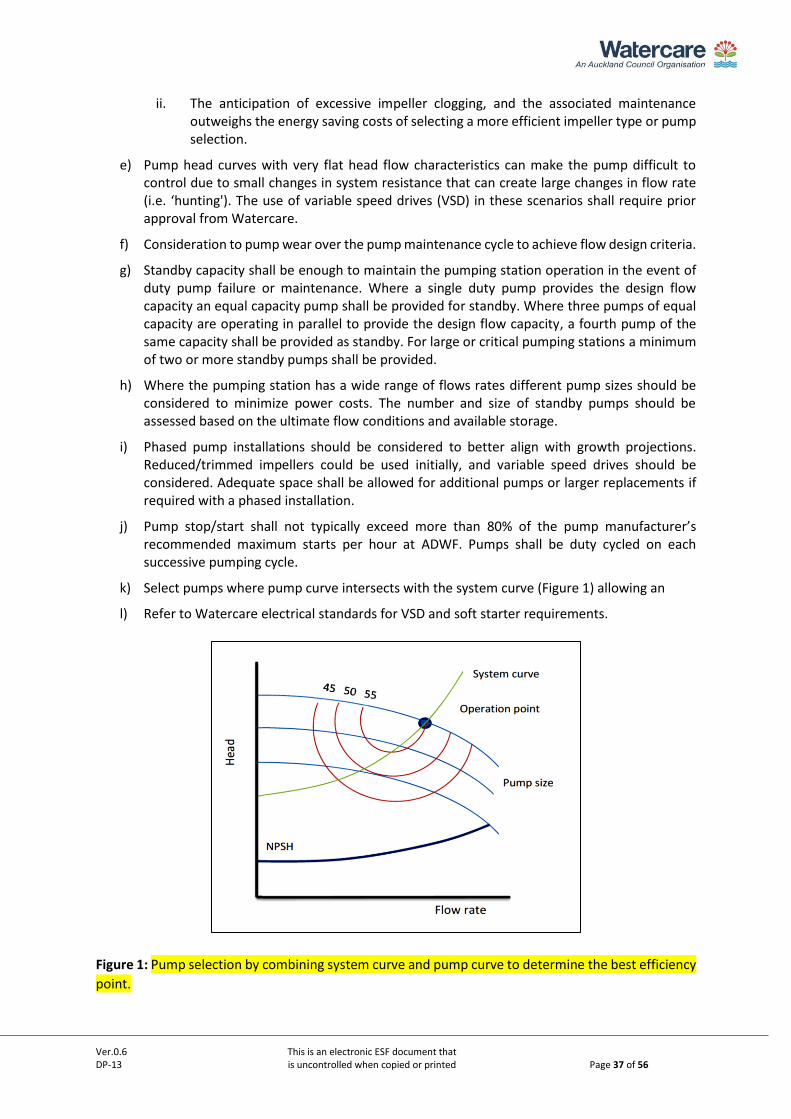
k) Select pumps where pump curve intersects with the system curve (Figure 1) allowing an
l) Refer to Watercare electrical standards for VSD and soft starter requirements.
Figure 1: Pump selection by combining system curve and pump curve to determine the best efficiency
point.
Ver.0.6 This is an electronic ESF document that DP-13 is uncontrolled when copied or printed Page 38 of 56
10.3. Pump product requirements The pump shall comply with the standards as listed and amended in Watercare’s material supply
standard.
11. Rising main 11.1. General a) The length of the rising main must be kept as short as possible.
b) The rising main shall be designed in accordance with Watercare Standard DP-07
c) Rising mains shall not be situated in private properties.
d) The rising main layout shall include a connection for bypass pumping.
11.2. Hydraulic design The rising main pipe shall be designed in combination with the pumping system (see section 10 above)
and include:
a) Length of the main and overall allowable detention time of up to 8 hours.
b) Maximum allowed number of pump starts and the impact of cyclic fatigue on the selected rising main material.
c) Withstand surge pressures not less than 200kPa. Pressure surges shall be within the amplitude of the acceptable limits throughout the system. The surge analysis shall consider the material fatigue of the selected pipe material and the derived maximum allowable operating pressure. The design shall identify solutions for Watercare’s approval to mitigate the surge effects.
Pressure surge solutions may include:
• Fast closing non-return valves.
• Controlled ramping up and ramping down of pumps.
• Slow-closing non-return valves.
This control method is before the pump stops. In such situations the pump control needs
to be co-ordinated, especially for power failure scenarios. Such non return valves will be
hydraulically controlled to shut between 20-30 seconds, or actuated valves could be
used.
• Pressure relief valve
d) Withstand a transient pressure of at least 80kPa below atmospheric pressure. Negative pressures can be prevented by:
• Pump inertia/flywheel to continue pump rotation for a short period after power
failure.
• Surge tank.
• Double acting air relief valves.
• Air vessel.
e) The minimum flow velocity shall be 0.9m/s. The minimum flow velocity shall be calculated at the expected start of the service life. The design shall be carried out based on full-bore flow
f) The maximum rising main flow velocity shall not be more than 3m/s at ultimate service at PWWF and not more than 2m/s at the PDWF or the flow rate at which the pump station normally or most frequently operates at.
Ver.0.6 This is an electronic ESF document that DP-13 is uncontrolled when copied or printed Page 39 of 56
g) The dynamic and static head.
h) Head loss shall be calculated using the Darcy-Weisbach equation with frictional coefficients determined using the Colebrook-White equation. A pipe roughness of 0.3mm shall be used in calculating the Colebrook-White friction factor (f). A Colebrook-White friction coefficient of 0.3 shall be used
i) Minor losses due to fittings, valves and other obstructions shall be determined using the component manufacturer’s value with a 10% inaccuracy factor. Where no data is available refer to Watercare’s design principles for transmission pipeline systems on manufactured fitting losses.
11.3. Rising main levels a) The rising main shall, wherever possible, rise continuously from the pumping station and
terminate at its upper end into the receiving structure.
b) Rising and falling mains (complex rising mains) shall be considered only when continuously
rising mains are not feasible
c) The minimum rising or falling grade shall be 0.5%.
Where a continuously rising main is not achievable the following shall be provided for:
d) Peaks and low points shall be minimised.
e) Peaks shall be constructed with a double acting air release valve structure. The air release chamber shall be fitted with suitable ventilation and treatment of foul air at the expected air flow rate.
f) Low points shall be prominent and shall incorporate a scour valve with pump-out arrangement that allows for safe access by a sucker truck and staff, refer to section 8 above.
g) Scour valve and air release valve chamber access shall where practical be in the back berm of the road corridor (the first 1m width of the road berm adjacent to the road carriageway is defined as the front berm).
11.4. Parallel rising mains a) Under exceptional circumstances, parallel pumping may be considered. For existing systems
where the design basis is for a completely new parallel system or where the existing systems
are redesigned and replaced a specific design philosophy must be developed and approved
by Watercare.
b) All pipelines operating in parallel shall be duty mains. Standby mains are not accepted due to
operational constraints with maintenance and septicity in the standby mains.
c) The operating points for parallel pumping stations shall be considered for the full system to
set individual pump duty points based on the pumping head for each pumping station or
pump set. The combined output shall be graphically determined using the individual
geodetic heads; head loss components for each pumping station to the discharge point and
then combined onto a single graph.
d) Where the common rising main is a complex rising main the graphical determination shall be
supported by modelling software. Watercare prefers that the modelling information is
provided in InfoWorks.
Ver.0.6 This is an electronic ESF document that DP-13 is uncontrolled when copied or printed Page 40 of 56
PART C – PUMP STATION TYPE SPECIFIC CONSIDERATIONS
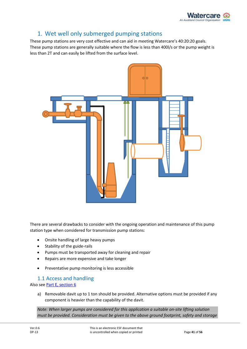
Ver.0.6 This is an electronic ESF document that DP-13 is uncontrolled when copied or printed Page 41 of 56
1. Wet well only submerged pumping stations These pump stations are very cost effective and can aid in meeting Watercare’s 40:20:20 goals.
These pump stations are generally suitable where the flow is less than 400l/s or the pump weight is
less than 2T and can easily be lifted from the surface level.
There are several drawbacks to consider with the ongoing operation and maintenance of this pump
station type when considered for transmission pump stations:
• Onsite handling of large heavy pumps
• Stability of the guide-rails
• Pumps must be transported away for cleaning and repair
• Repairs are more expensive and take longer
• Preventative pump monitoring is less accessible
1.1 Access and handling Also see Part E, section 6
a) Removable davit up to 1 ton should be provided. Alternative options must be provided if any
component is heavier than the capability of the davit.
Note: When larger pumps are considered for this application a suitable on-site lifting solution
must be provided. Consideration must be given to the above ground footprint, safety and storage
Ver.0.6 This is an electronic ESF document that DP-13 is uncontrolled when copied or printed Page 42 of 56
of the solution or transport and manoeuvring on site. Suitable solutions may include external
gantry cranes or jib cranes.
b) Man-access to the valve chamber and grit chambers are required.
c) Lid clearance should be provided to lifting any equipment from the surface
d) Pump guiderails shall be Schedule 80 Grade 316 stainless steel to prevent corrosion. The
guiderails shall have adequate support brackets to prevent rails from bending or buckling.
e) Pump lifting chains are to be tethered to the wet well opening with sufficient chain length to
allow loop at top of wet well.
f) Access shall be provided to the wet well invert for operations. This includes any platforms
required for ladders. The landing platform shall be above the high-high water level and
access below the platform to the invert of the wet well shall preferably be by portable
ladder or fixed installed slide down or fold down ladder from the platform. Fixed installed
ladders below the high-high level would increase the risk of trapping floating debris and
rags.
1.2 Monitoring and control Also see Part D.
a) Control cabinets must be installed above ground.
b) Cable ducting must not be continuous from the wet well to the control cabinets to prevent
gasses from entering the control cabinet.
1.3 Pump Intake a) The centre-to-centre clearance between pump intakes shall be designed in accordance with
industry standards and as required by the pump manufacturer to prevent vortices, air
entrapment and pre-swirl.
b) The side clearance from the centre of the pump intakes to the well walls shall be designed in
accordance with industry standards and as required by the pump manufacturer
c) Height of the pump intake off the wet well floor shall be in accordance with the pump
manufacturer’s specification.
1.4 Pump Selection a) Pump selection will be a pump with proven anti-clog performance
1.5 Wet Well Material a) GRP is preferred for wet wells 4.5m in diameter or less, and less than 9m deep due to cost
and carbon benefits, and benefits of off-site fabrication. GRP structural design is to be by the
GRP tank vendor. A structural loadings memo is to be provided to the manufacturer
outlining the structural design requirements.
b) For very deep wet wells (>9m) and wet wells in ground conditions that require extensive
temporary works (i.e. secant piles), consideration should be given to designing temporary
works to be incorporated into the permanent works (i.e. secant pile walls or caisson).
Corrosion resistance is to be applied as per Section 4.2, Part B.
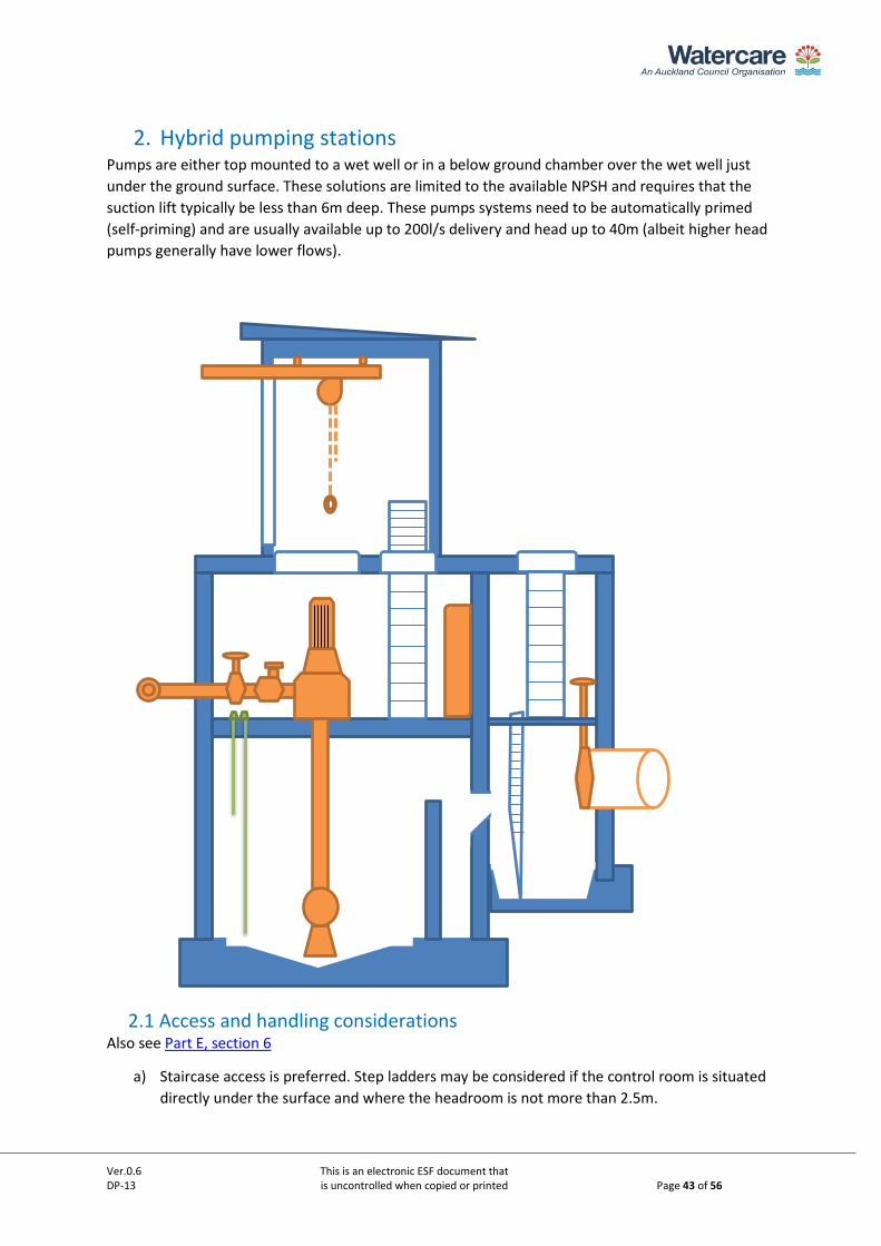
Ver.0.6 This is an electronic ESF document that DP-13 is uncontrolled when copied or printed Page 43 of 56
2. Hybrid pumping stations Pumps are either top mounted to a wet well or in a below ground chamber over the wet well just
under the ground surface. These solutions are limited to the available NPSH and requires that the
suction lift typically be less than 6m deep. These pumps systems need to be automatically primed
(self-priming) and are usually available up to 200l/s delivery and head up to 40m (albeit higher head
pumps generally have lower flows).
2.1 Access and handling considerations Also see Part E, section 6
a) Staircase access is preferred. Step ladders may be considered if the control room is situated
directly under the surface and where the headroom is not more than 2.5m.
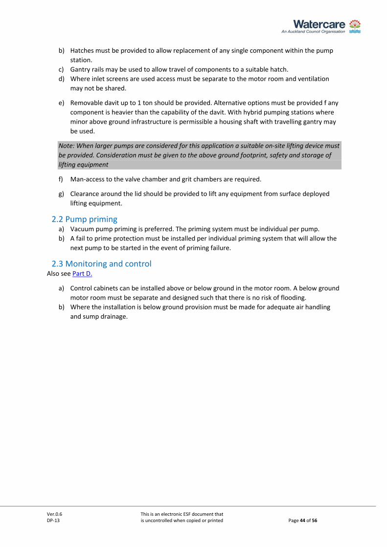
Ver.0.6 This is an electronic ESF document that DP-13 is uncontrolled when copied or printed Page 44 of 56
b) Hatches must be provided to allow replacement of any single component within the pump
station.
c) Gantry rails may be used to allow travel of components to a suitable hatch.
d) Where inlet screens are used access must be separate to the motor room and ventilation
may not be shared.
e) Removable davit up to 1 ton should be provided. Alternative options must be provided f any
component is heavier than the capability of the davit. With hybrid pumping stations where
minor above ground infrastructure is permissible a housing shaft with travelling gantry may
be used.
Note: When larger pumps are considered for this application a suitable on-site lifting device must
be provided. Consideration must be given to the above ground footprint, safety and storage of
lifting equipment
f) Man-access to the valve chamber and grit chambers are required.
g) Clearance around the lid should be provided to lift any equipment from surface deployed
lifting equipment.
2.2 Pump priming a) Vacuum pump priming is preferred. The priming system must be individual per pump.
b) A fail to prime protection must be installed per individual priming system that will allow the
next pump to be started in the event of priming failure.
2.3 Monitoring and control Also see Part D.
a) Control cabinets can be installed above or below ground in the motor room. A below ground
motor room must be separate and designed such that there is no risk of flooding.
b) Where the installation is below ground provision must be made for adequate air handling
and sump drainage.
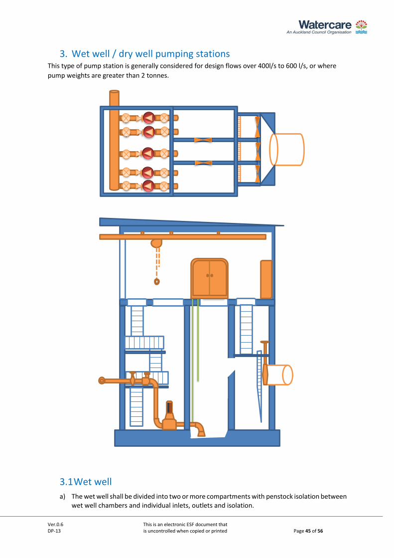
Ver.0.6 This is an electronic ESF document that DP-13 is uncontrolled when copied or printed Page 45 of 56
3. Wet well / dry well pumping stations This type of pump station is generally considered for design flows over 400l/s to 600 l/s, or where
pump weights are greater than 2 tonnes.
3.1 Wet well
a) The wet well shall be divided into two or more compartments with penstock isolation between wet well chambers and individual inlets, outlets and isolation.
Ver.0.6 This is an electronic ESF document that DP-13 is uncontrolled when copied or printed Page 46 of 56
b) Penstock valves are suitable for inlets in the wet well.
c) Benching shall be formed (fluted) to guide flow towards the pump suction, not pass solids from one pump suction to another and to achieve self-cleaning.
d) Access to the wet well needs to be provided by staircase to landing platforms that are designed to AS/NZS1657.
3.1.1 Pump intakes (wet well outlet pipework) a) The pump intake pipe shall be formed with a long radius bend facing downwards and a bell-
mouth.
b) The centre-to-centre clearance between pump intakes shall be a minimum of 1.5 times the external pipe diameter, or as otherwise required by the pump supplier to prevent vortices, air entrapment and pre-swirl.
c) The side clearance from the centre of the pump intakes to the well walls shall be minimum 0.8 times the external pipe diameter, or as otherwise required by the pump supplier.
3.2 Dry well The drywell needs to provide adequate clearances around machinery and equipment for visual
inspection, routine maintenance and replacement with the following consideration:
a) Structural design shall be to the selected function class.
b) General clearances around valves and pipework as stipulated in the Watercare Design
principles for transmission water and wastewater pipeline design, DP-07 Part C, and as
described by the Health and Safety in Facility design guidelines.
c) Adequate space for future replacement with larger diameter pipework and components.
d) The discharge manifold layout shall be designed to prevent solids settling and building up
within pipework .
e) Suitable drainage must be included to maintain the chamber in a dry condition from any
seepage. The floor must be graded to a sump location with sump pump that discharges
above the flood level.
a) 3.1.1 Sump pumps shall be duty standby and monitored.
b) The drywell sump shall be fitted with a level alarm.
3.3 Access and handling considerations Also see Part E, section 6
a) The drywell building shall be fitted with a running gantry that is able to lift any equipment
from the installed position onto the back of a truck.
b) Access shall be made available for truck hard-stand and suitable service doors to allow
equipment or vehicle handling.
c) Access shall generally be by staircase.

Ver.0.6 This is an electronic ESF document that DP-13 is uncontrolled when copied or printed Page 47 of 56
PART D – ELECTRICAL, CONTROL AND TELEMETRY
Ver.0.6 This is an electronic ESF document that DP-13 is uncontrolled when copied or printed Page 48 of 56
1. Electrical, Control and Telemetry Electrical, control and telemetry design and installation shall comply with the Watercare electrical and
control standards and template drawing set DW18 for pumping stations.
1.1. Electrical Additional to the electrical standards the following requirements for establishing electrical power on
site shall also be completed:
• Sites owned by Watercare shall be coordinated for connection through Watercare. Early engagement with the mains provider is required.
• Where mains electricity is not available at the site a new installation point (ICP) will be provided.
• Mains electricity shall be of sufficient capacity considering future expansion.
• Unless otherwise approved, substations on an electrical consumer’s premises shall be for the sole supply of the Watercare facility.
• Information required for the ICP include supply phase; maximum demand load in amps; physical address of connection; name and contact of the electrical contractor undertaking the works.
• Any easement requirements for electrical mains and transformers must be referred to Watercare.
1.2. Control system and Telemetry a) Watercare will complete a connection suitability study for the location, to establish the
telemetry requirements for the proposed pumping station site. A desk study will determine
if there is an available connection for the location.
b) If a connection is possible, the desktop study is followed by a site check to establish the
signal to noise level ratio to ensure a good quality signal is available.
c) Should there be no communications available, or the signal strength is less than -90dB a
specific design will be required.
d) The telemetry and radio system shall be from a Watercare standardised supplier, refer to
Watercare’s material supply standard. The installation shall be carried out by a Watercare
approved contractor.
e) The designer shall obtain a facility code from Watercare that is used to provide the tag
information used to configure the control system. The information required to obtain the
facility code is:
• GIS location of the site
• The physical address associated with the site
• Lot number or Land Registry identification
f) The SCADA software shall be developed and implemented by a Watercare approved
developer.
g) Watercare has five different control systems that operate in various areas, they are:
• Emerson DCS
• In Touch SCADA
• IFIX LNT SCADA
Ver.0.6 This is an electronic ESF document that DP-13 is uncontrolled when copied or printed Page 49 of 56
• Citect SCADA
• Abbey Systems Powerlink
For Watercare to complete the SCADA the following will be developed and supplied by the
designer:
i. A level one Functional Description (FD), to be reviewed and accepted by Watercare before software programming commences.
ii. Liaise with Watercare point of contact in the production of the Electrical/ Control system design.
iii. Process and instrumentation diagrams (P&IDs).
iv. Bill of materials.
v. Confirmed Input and Output lists (I/O).
Ver.0.6 This is an electronic ESF document that DP-13 is uncontrolled when copied or printed Page 50 of 56
PART E – INFRASTRUCTURE AND SUPPORT SYSTEMS
Ver.0.6 This is an electronic ESF document that DP-13 is uncontrolled when copied or printed Page 51 of 56
1. Water supply a) A metered water supply with reduced pressure zone backflow preventer (RPZ) shall be
installed to allow for wash-down and general cleaning. See G12/AS1 of the Building Code,
for the methods and devices required to comply with Watercare’s requirements.
b) Where firefighting supply is not within reach as per the New Zealand Code of Practice for
Firefighting Water Supplies, then a suitable firefighting supply shall be installed in
accordance with the Watercare Code of Practice for Land Development and Subdivision,
Chapter 6.
1.1. Ablution facilities a) The need for toilet and washing facilities shall be agreed with Watercare Operations and
provided if required.
2. Lighting a) Where considered an operational requirement or for safety reasons, site lighting must be
specified. The designer must confirm the requirement and location such as to provide
adequate lighting and not have obstructive and obtrusive effects. The lighting shall be
adequately controlled to prevent annoyance to the neighbouring properties.
b) Lighting shall be provided at the pump station control room and dry well. Lighting shall
provide proficient lighting to allow 24-hour operability and functions for maintenance.
c) Fluorescent lights should be avoided and shall be phase shifted to stop strobe effects on
machine rotating shafts where accepted to be used.
d) Positioning of lights shall be such that cast shadows or unlighted areas are avoided
e) The design shall consider the types of activities to ensure the safety of people for the task
types in the pumping station environment so that any hazards are visible and well lit.
3. Ventilation a) The ventilation characteristics must be documented.
b) The wet well shall not be ventilated to the dry well or the control room. The wet well
ventilation shall be designed in accordance with the inflow velocity and shall achieve a
minimum of 12 air changes per hour at a rate to meet the inflow velocity The dry well shall
not be ventilated to the control room.
c) The dry well shall have a minimum of 6 air changes per hour.
d) The control room shall have a minimum of 10 air changes per hour within the limitations of
AS/NZS61439 and be fitted with replaceable filters. Cooling of the control room shall be
provided where ventilation is not sufficient to control the temperature of the room
Note: Air changes may be adjusted on review of the requirements of the equipment suppliers.
4. Site drainage a) The site shall have adequate drainage and fall to prevent standing or ponding water and
prevent inflow into dry areas.
b) Overland drainage shall not affect neighbouring properties and may require a storm water
system to be installed for discharge to a suitable location.
Ver.0.6 This is an electronic ESF document that DP-13 is uncontrolled when copied or printed Page 52 of 56
5. Noise control and vibration a) Noise generated by the pumping station shall not exceed the Council permitted levels. The
design shall include measures to reduce noise appropriately. Where the maximum noise
level has not been specified in the resource consent the maximum shall level be 45 dB LAeq
(15min) measured at the pumping station boundaries.
b) Strong and long-term vibrations can cause soil settlement in certain soil types as well as
long-term structural problems. Apart from the effects on physical structures vibration may
also cause discomfort to adjacent property occupiers. The vibration velocity level shall not
exceed 1mm/s measured at the pumping station wet well.
6. Lifting equipment a) Lifting devices shall comply with AS1418, AS4991 and the Worksafe NZ Approved Code of
Practice for Cranes.
b) Adequate access shall be provided for mobile lifting plant around the pumping station
installation and suitable hard stand areas.
c) Overhead gantry cranes or jib cranes shall be provided for handling large pumps, motors and
valves.
The design of lifting equipment shall reflect:
i. The design safe working load (SWL shall be suitable for the heaviest component in the
plant.
ii. Equipment may need to be lifted in part or assembled.
iii. Positioning of equipment and the lifting cover area. In some instances, the layout may
require more than one gantry. The positioning shall provide for lifting equipment or
parts onto and off trucks.
iv. Structural design required where the crane girders and runways form part of the
building design. It should be considered that cranes may be used as part of the
temporary works when the pump station is constructed to lift materials and
components into the build.
v. Permanent access needs to be provided for overhead cranes. Isolators must be
provided adjacent to the crane access.
7. Security, access and fire alarms a) All cabinets and access manholes not accessible through the main pump station building
shall be lockable.
b) All entry points shall be fitted with an alarm that will signal unauthorised access through the
Watercare security system. Security systems are to be fitted with a dual communications
option that provides alarm to Watercare’s security supplier and the Watercare central
control room.
c) Fire alarms shall be monitored for high priority pumping stations. Fire alarm systems are to
be fitted with a dual communications option that provides alarm to Watercare’s service
supplier and the Watercare central control room. Lower priority pumping stations may be
fitted with a smoke alarm at the control panel only that provides a fire alarm to the
Watercare central control room.
Ver.0.6 This is an electronic ESF document that DP-13 is uncontrolled when copied or printed Page 53 of 56
d) Access lids shall be to the standard Watercare details and supplied with ‘universal' padlocks
and locking bolts and shall allow for replacement with Watercare’s transmission wastewater
crox key.
e) Where access lids of larger sizes and traffic loading are required, the design shall comply
with AS3996.
f) Pump stations shall be fitted with fire detection equipment to meet the Building Act
requirements.
8. Signage a) Signage shall be provided that identifies the pumping station as the property of Watercare
b) Informative operational, health and safety signage is required at the pumping station
perimeter. Refer to Watercare’s mechanical construction standard.
9. Site access road a) The site access road shall comply with Watercare’s general civil construction standard.
b) Adequate vehicle turning area shall be provided within the site.
c) The access road shall be sealed have a minimum laden load bearing capacity of 25tons
(unless otherwise stated) and a minimum width of 3.5m.
10. Odour control a) Refer to DP-07 Design Principles for Transmission Water and Wastewater Pipeline
Systems, for odour control requirements.
Ver.0.6 This is an electronic ESF document that DP-13 is uncontrolled when copied or printed Page 54 of 56
Appendix A: Watercare Network Discharge Consent (NDC) executive summary
Introduction
This summary provides a high-level overview of the considerations for complying with the
wastewater network discharge permit in the Auckland region.
The consent authorises the discharge of wastewater from Watercare’s wastewater networks to land,
freshwater and coastal receiving environments in accordance with section 15(1)(a) and (b) of the
Resource Management Act 1991, during times of dry and wet weather flow.
The overflows may occur as a result of network blockages and failures; network damage by third
parties; failure at pump stations or storage facilities and capacity constraints. Once a pumping
station is in operation overflows must be minimised, continuously monitored and inspected.
Existing networks area:
• Discharge from any new engineered overflow point within the existing network is allowed provided that the discharge frequency is not more than two (2) Wet Weather Overflow Events per year and the location of the proposed overflow point is not in a Class 1 Recreational Receiving Environment.
• Should the above not be achievable then the Best Practical Option (BPO) methodology and an improvement strategy may be considered to determine an alternative overflow frequency and/or overflow location. This option must be acceptable to Watercare before submitting to Auckland Council. The acceptance does not guarantee approval by Auckland Council
• No discharge is allowed to a Tangata Whenua Management Area as identified in the Regional Plan: Coastal, or an equivalent area in the Unitary Plan where discharges are a prohibited activity.
Future networks area:
• Discharge from any new engineered overflow point which is zoned for urban activity under the relevant Resource Management Act statutory document, and is within a future network is allowed provided that:
o The overflow point is located within 500m of a predetermined proposed overflow location as shown on the relevant indicative future urban area map or of a similar location (see map attached below)
o The overflow point is designed and managed to achieve the discharge frequency of no more than two Wet Weather Overflow Events per year, and the location of the proposed overflow point is not in a Class 1 Recreational Receiving Environment
o A minimum of four (4) hours storage at Dry Weather Flow is provided at or near the overflow point, or more as may be specified.
• Discharge from any new engineered overflow in the Indicative Future Urban Area but not identified in the below map as a predetermined proposed overflow location requires certification from Auckland Council. Watercare’s agreement and guidance are required before making the application and should be based on the following criteria:
Ver.0.6 This is an electronic ESF document that DP-13 is uncontrolled when copied or printed Page 55 of 56
o The potential overall risk of the discharge is very low or low. This is to be determined by the applicant using Watercare’s Methodology for the Assessment of Effects of Wet Weather Wastewater Overflows. The methodology is available from Watercare
o The overflow point is designed and managed to achieve the discharge frequency of no more than two (2) Wet Weather Overflow Events per year, and the location of the proposed overflow point is not in a Class 1 Recreational Receiving Environment
o The Best Practical Option (BPO) methodology and an improvement strategy may be considered to determine an alternative overflow frequency and/or overflow location. This option must be acceptable to Watercare before submitting to Auckland Council. The acceptance does not guarantee approval by Auckland Council.
o Direct discharges to the coastal marine area shall be avoided unless an assessment using the BPO methodology demonstrates that this is the most suitable location, taking into account cultural and ecological factors.
• No discharge is allowed to a Tangata Whenua Management Area as identified in the Regional Plan: Coastal, or an equivalent area in the Unitary Plan where discharges are a Prohibited Activity.
• No overflow point shall be located on private property without the written consent of the property owner and other affected parties that they agree to the location of the overflow point.
Future networks outside mapped areas:
Where a discharge application is outside any of the identified areas of the map, the statutory
assessment of the application should be based on providing the same conditions of the existing
statutory assessment for the NDC with the following criteria:
• Watercare requires that the applications use Watercare’s Methodology for the Assessment of
Effects of Wet Weather Wastewater Overflows, the Best Practical Option (BPO) methodology
and an improvement strategy may be considered to determine an alternative overflow
frequency and/or overflow location. The methodology and templates are available from
Watercare
• For the purpose of gaining consent with Auckland Council, additional considerations may be
required under the Auckland unitary plan and if applicable existing regional plans
• Stakeholder reports demonstrating consultation with Watercare, Auckland Council, local boards,
Auckland Regional Health Services and Iwi.
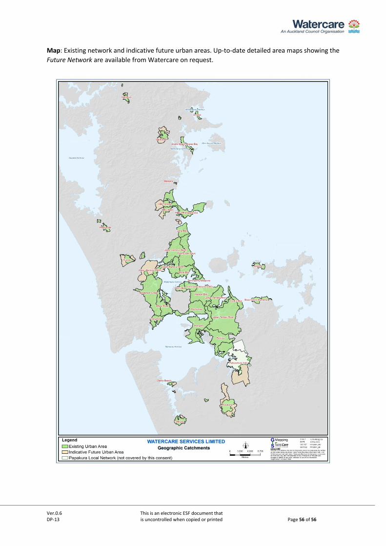
Ver.0.6 This is an electronic ESF document that DP-13 is uncontrolled when copied or printed Page 56 of 56
Map: Existing network and indicative future urban areas. Up-to-date detailed area maps showing the
Future Network are available from Watercare on request.