
Design of tube hydroforming machine and its application
44
Design of tube hydroforming machine and its application YAMAMOTO SUIATU KOGYOSHO Co.,LTD.
Transcript of Design of tube hydroforming machine and its application

Design of tube hydroforming machine
and its application
YAMAMOTO SUIATU KOGYOSHO Co.,LTD.

Basic tube hydroforming process sequence
Draw bending
machine
Design of tube hydroforming machine
Preforming Hydroforming
Preforming press Hydroforming press
Prebending
(Draw bending)

Hydroforming press Preforming press
A typical example of machine arrangement
for hydroforming process sequence
Draw bending
machine

Design of draw bending machine (1)
Compression booster
Pressure die assist booster
Rotational
bending form
Movable pressure die
Clamp die
Wiper die
Mandrel
Pressure die assist booster
Compression booster
Pressure die
Axial compressive force
Forward frictional force

Pressure die assist booster
Compression booster
Design of draw bending machine (2)
Axial compressive force is effective to increase
the thickness of the bend after the subsequent
hydroforming.
Forward frictional force is effective to decrease the
reduction of the peripheral length of the bend during
the draw bending.

Design of draw bending machine (3)
R1
R2
R1
R2
Stacked bending forms for different radius
bends progressively in one part (number of
bending forms: 2~5)
Pressure die
R1R1
R1R1
R2R2

An example of draw bending machine in the
hydroforming process sequence
Draw bending of tube for an engine cradle

Punch
Die set
Die set
Punch
Die set
Die set
Common plate
Design of preforming press
Multi-purpose pressSingle-purpose press(An example for an engine cradle)
Horizontal
cylinders
Slide cylinder
Slide
Moving
bolster

An example of single-purpose preforming press
Vertical cylinder:1,500KN

Examples of multi-purpose preforming press
2,000KN 3,500KN

Basic composition of hydroforming machine
Oil reservoir
High pressure
medium
Low pressure
medium
Oil
Pressure intensifier
Horizontal
cylinders for
axial feeding of
tube ends
Die closing press (machine)
Pressure
medium
reservoirOil
reservoir
Filter

Retro-fit hydroforming press
Re-use of hydraulic press as a hydroforming press by
adding the horizontal cylinders and pressure intensifier
Pressure intensifier
Pressure medium
reservoir
Equipment for driving
horizontal cylinders

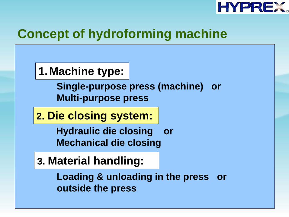
Concept of hydroforming machine
2. Die closing system:
3. Material handling:
Single-purpose press (machine) or
Multi-purpose press
Hydraulic die closing or
Mechanical die closing
Loading & unloading in the press or
outside the press
1.Machine type:

Single-purpose hydroforming press
Features: (1) Fixed target product
(2) Compact press size (Height & Area)
(3) High productivity
Slide cylinder
with a minimum
force and stroke
necessary to the
die closing
Horizontal cylinder
with a minimum
force and stroke
necessary to the
axial feeding of the
tube end

Examples of single-purpose hydroforming press
Die closing force:15,000KN Die closing force:8,000KN

Multi-purpose hydroforming press (1)
Space with area and
height necessary to
setting the largest
die set and handling
the workpiece
Slide cylinder with
force and stroke
necessary to
closing all die sets
(2) Horizontal cylinders for axial feeding of Features: (1) Conventional hydraulic press
Die set with
horizontal cylinders
tube ends are installed in each die set.

Multi-purpose hydroforming press (2)
Features: (1) Flexible positioning of horizontal cylinders on the bed
(2) Horizontal cylinders are commonly used for several die sets.
Bed
Horizontal cylinders

Die closing force:35,000KN Die closing force:35,000KN
Examples of multi-purpose hydroforming press(1)

Die closing force:50,000KN
Examples of multi-purpose hydroforming press(2)
Concept of hydroforming machine
2. Die closing system:
3. Material handling:
Single-purpose press (machine) or
Multi-purpose press
Hydraulic die closing or
Mechanical die closing
Loading & unloading in the press or
outside the press
1.Machine type:

Hydraulic die closing
Slide cylinder
Table cylinder
Top die
Bottom
die
Die set
Slide
Table
(1)Die closing by slide cylinder
(2)Die closing by table lifting cylinder

Mechanical die closing (1)
Cylinders for axial
feeding of tube ends
Transverse clamping of top and bottom dies
Top die lifting cylinder
Die-clamping cylinder
Clamping tool
Bottom die
Top die

Mechanical die closing (2)
Longitudinal clamping of top and bottom dies
Die holder
Die-clamp ring
Top die lifting cylinder
Die
Conical face

Concept of hydroforming machine
2. Die closing system:
3. Material handling:
Single-purpose press (machine) or
Multi-purpose press
Hydraulic die closing or
Mechanical die closing
Loading & unloading in the press or
outside the press
1.Machine type:

Material handling
Sufficient space for
loading and unloading
by robot arm
(1)Loading and
unloading in the
press
(2)Loading and
unloading outside
the press
Minimum space for
separating top and
bottom dies
Minimized
machine height
Automatic moving of bottom die

Specifications of hydroforming press
Die closing force
Axial feeding of tube ends
Pressure intensifier
Quick die change system
Productivity
Moving bolster etc.
Maximum pressure, Pressure control
Axial feeding force Double acting horizontal cylinder
Parallel forming, Shuttle die
Standard classification

Standard classification of die closing force
~10,000KN
15,000KN
25,000KN
35,000KN
Class of die
closing force
Automotive parts in
mass production
(Japan)
Sub-frames
Cross members
etc.Perimeter frames
Cross members
etc.Suspension members
Engine cradles
Cross members etc.
50,000KN Cross members etc.
Exhaust parts
Steering parts etc.
Top die
Bottom die Pmax
F
Die closing force F≧Pmax×A
A: Vertically projected
area of die cavity

Specifications of hydroforming press
Die closing force
Axial feeding of tube ends
Pressure intensifier
Quick die change system
Productivity
Moving bolster etc.
Maximum pressure, Pressure control
Axial feeding force Double acting horizontal cylinder etc.
Parallel forming, Shuttle die
Standard classification

pFa
Axial feeding force of tube end
Rough estimation of Fa (max)
Fa (max)=A1・σb+A2・Pmax
σb: Ultimate tensile strength of tubePmax: Maximum internal pressure
A1: Area of cross section of tube wall
A2: Area of cross section
inside the tube
Axial feeding of tube ends
Pmax
Inte
rna
l p
res
su
re P

Top die
Bottom
die
Energy-saving horizontal cylinder
Pressure medium
Hydraulic fluid
Patented
Pressure medium chamber for
compensating the internal pressure
Sealing punch

Double-acting horizontal cylinder
Features: (1) Co-axial inner and outer cylinders(2) Independent feed control
Outer cylinder
Inner cylinderpressure medium
pathPatented

Functions of double-acting horizontal cylinder (1)
Die segment case
Small corner radius
Movable die segments
Axial feeding of tube end
by inner cylinderAxial feeding of die segments
by outer cylinder

Functions of double-acting horizontal cylinder (2)
-20
-15
-10
-5
0
5
10
15
20
25
-210
-180
-150
-120
-90
-60
-30 0
30
60
90
120
150
180
210
Distance from the center in mm
Th
ick
nes
s st
rain
in %
Conventional method New method
TubeTube Expanding zone
φ78.8
φ60.5
245mm
Frictional
force
Frictional
force is
minimized

Specifications of hydroforming press
Die closing force
Axial feeding of tube ends
Pressure intensifier
Quick die change system
Productivity
Moving bolster etc.
Maximum pressure, Pressure control
Axial feeding force Double acting horizontal cylinder
Parallel forming, Shuttle die
Standard classification

Pressure intensifier
High pressure medium (Water containing emulsion oil of a few percent)
Hydraulic
cylinderServo
valve
High pressure
chamber
Maximum pressure
200~400MPaPressure
sensor

Control of internal pressure with axial feeding
of tube ends
dA
dB
A
BC
Zone not affected by axial feeding
of tube ends
dAdB
ABCPf
Pi
Inte
rnal
pre
ssu
re
Axial feeding of tube end
Large expansion
ratio
Small expansion
ratio

Specifications of hydroforming press
Die closing force
Axial feeding of tube ends
Pressure intensifier
Quick die change system
Productivity
Moving bolster etc.
Maximum pressure, Pressure control
Axial feeding force Double acting horizontal cylinder
Parallel forming, Shuttle die
Standard classification

Improvement of productivity by parallel forming
LoadingLoading
Unloading Unloading
Die set A Die set B

Cycle-time reduction by shuttle die system
Unloading
& loading
work-piece
Unloading
& loading
work-piece
Hydroforming stage
Hydroforming stage
Shuttle bottom die

Specifications of hydroforming press
Die closing force
Axial feeding of tube ends
Pressure intensifier
Quick die change system
Productivity
Moving bolster etc.
Maximum pressure, Pressure control
Axial feeding force Double acting horizontal cylinder
Parallel forming, Shuttle die
Standard classification

Quick die change system (1)
Moving bolster
Set-up position rightSet-up position left
Traversing direction left-right
Set-up position back
Traversing direction front-back

Quick die change system (2)
Automatic coupling device
Horizontal
cylinder(1)
Knock-out
cylinders
Piercing
cylinders
Horizontal
cylinder(2)
Hydraulic fluid for
knock-out cylinders
Hydraulic fluid for
piercing cylinders
Low pressure medium
Hydraulic fluid for
horizontal cylinder(1)
Hydraulic fluid for
horizontal cylinder(2)
Die
Die plate
High pressure medium
Piping in hydroforming die Piping in hydroforming machine

Examples of automatic coupling device
Die side
Machine side
Die side
Machine side

The End