TORNADO CABLE AND TUBE BLOWING MACHINE OPERATION & …
62
TORNADO CABLE AND TUBE BLOWING MACHINE OPERATION & MAINTENANCE 89000 – USA CABLE BLOWING MACHINE Copyright 2017 by General Machine Products (KT), LLC All rights reserved. No part of this publication may be copied, reproduced or transmitted in any form whatsoever without the written permission of General Machine Products (KT), LLC General Machine Products (KT), LLC • 3111 Old Lincoln Hwy • Trevose, PA 19053 • USA TEL: +1-215-357-5500 • FAX: +1-215-357-6216 • EMAIL: [email protected] QC Final Inspection by:_________________________ Date:__________________ Unit Serial Number:__________________ Build Date:__________________ Manual P/N 32613 September 18, 2017 USA Ver 2 rev
Transcript of TORNADO CABLE AND TUBE BLOWING MACHINE OPERATION & …

Page 1 of 62 General Machine Products (KT), LLC
TORNADO CABLE AND TUBE BLOWING MACHINE OPERATION & MAINTENANCE
89000 – USA CABLE BLOWING MACHINE
Copyright 2017 by General Machine Products (KT), LLC
All rights reserved. No part of this publication may be copied, reproduced or transmitted in any form whatsoever without the written permission of General Machine Products (KT), LLC
General Machine Products (KT), LLC • 3111 Old Lincoln Hwy • Trevose, PA 19053 • USA TEL: +1-215-357-5500 • FAX: +1-215-357-6216 • EMAIL: [email protected]
QC Final Inspection by:_________________________ Date:__________________
Unit Serial Number:__________________
Build Date:__________________
Manual P/N 32613 September 18, 2017 USA Ver 2 rev

Page 2 of 62 General Machine Products (KT), LLC
REVISION HISTORY:
Rev No
Date Details Author
01 01-2006 Original issue A. Miller
02 02-2006 Programming Instructions Updated A. Sibun
03 07-2006 New photo with air inlet pipe added A. Crawford
04 12-2006 Cable seal, collets and plug selection chart updated A. Miller
05 02-2007. Recommended spares list revised A. Crawford
06 01-2008 Programming Instructions Updated A. Sibun
07 03-2008 Programming Instructions Updated A. Sibun
08 11-2009 US GMP Version 1 A. Konschak
09 04-2011 Updated photos and pressure adjustments A. Konschak
10 07-2011 Various updates Version 2 A. Konschak
11 01-2012 Added 3/4” collet accessory A. Konschak
12 10-2012 Added updated Recommended Spare Parts A. Konschak
13 07-2014 Added color code chart to configuration page A Konschak
14 10-2016 Update recommended blowing lubricant qty. and photo A Konschak
15 11-2016 Update to supplied tools on p 37 A Konschak
16 12-2016 Added tool photos to p31. Update seals list. A. Konschak
17 04-26-17 Update hex key size for pressure switch on P 34 A. Konschak
18 06-29-17 Updated legal name of company A. Konschak

Page 3 of 62 General Machine Products (KT), LLC
CONTENTS 1. Safety Instructions 2. Critical Points 3. General Description 4. Specification 5. Operating Procedure - Sub-Duct Integrity and Lubrication 6. Operating Procedure—Cable Blowing 7. Maintenance 8. Procedure for Replacement of Chain Drives 9. Procedure for Replacement of Cable Collets 10. Procedure for Replacement of Sub-Duct Clamp Collets 11. Procedure for Replacement of Cable Seals 12. Procedure for Adjusting the Air Chamber and collet type cable infeed guide assembly height 13. Alignment of air chamber to the cable pusher unit 14. Monthly Service Check List 15. Service History Record 16. Troubleshooting Guide 17. Recommended Spare Parts APPENDICES Appendix 1 Layout of Cable Blowing Machine Appendix 2 Reserved Appendix 3 Cable Blowing Machine Service Connections Appendix 4 Hydraulic & Electrical Panel Layout Appendix 5 Appendix 6 Tornado Configuration Guide Appendix 6 Counter/Rate meter Programming Instructions Appendix 7 Flow and Pressure Control Manifold GMP Limited Warranty can be found at http://www.gmptools.com/warranty/
Page 4 of 62 General Machine Products (KT), LLC
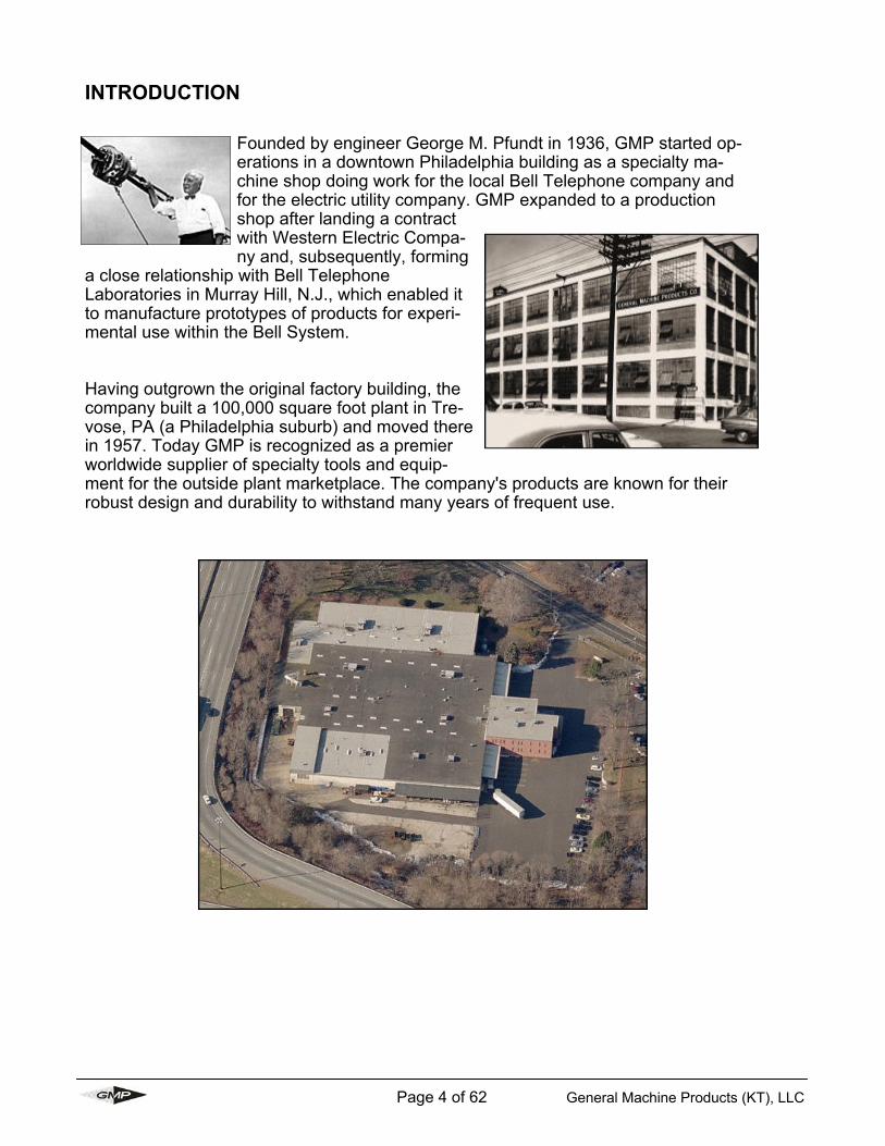
Founded by engineer George M. Pfundt in 1936, GMP started op-erations in a downtown Philadelphia building as a specialty ma-chine shop doing work for the local Bell Telephone company and for the electric utility company. GMP expanded to a production shop after landing a contract with Western Electric Compa-ny and, subsequently, forming
a close relationship with Bell Telephone Laboratories in Murray Hill, N.J., which enabled it to manufacture prototypes of products for experi-mental use within the Bell System. Having outgrown the original factory building, the company built a 100,000 square foot plant in Tre-vose, PA (a Philadelphia suburb) and moved there in 1957. Today GMP is recognized as a premier worldwide supplier of specialty tools and equip-ment for the outside plant marketplace. The company's products are known for their robust design and durability to withstand many years of frequent use.
INTRODUCTION
Page 5 of 62 General Machine Products (KT), LLC
1. SAFETY INSTRUCTIONS This equipment must only be used by authorized personnel who have been suitably trained and competent to do so. These instructions are to be made available to operators of this equipment at all times. Failure to observe these safety instructions could result in se-rious personal injury and or property damage. WORK AREA AND GENERAL SAFETY 1) Read and understand the operation and maintenance manual supplied with this equip-ment. Keep it in a convenient place for future reference. 2) Keep children and untrained personnel away from this equipment while in operation. 3) Keep all guards and safety devices in place. Do not operate this equipment with guards removed or damaged. 4) Keep hands, feet and loose clothing away from moving parts, especially at cable entry points. 5) Always stop the machine and isolate, compressed air, electrical and hydraulic services to carry out lubrication and servicing. 6) Check machine before starting for worn or damaged parts. Check that all nuts and bolts are tight. 7) If machine is left unattended, ensure that unauthorized use is prevented. 8) Never leave the machine unattended while in use. 9) Consider the use of safety barriers, especially when used in public places. 10) Beware of pinch points involved with rotating components, e.g. screw operated tractor drive lifting mechanisms. 11) Beware of hot surfaces, machine uses compressed air and hydraulic services. 12) When operating machine always wear eye protection, hard hat, safety shoes and leather gloves, machine operates with compressed air at 175 psi (12 bar) and hydraulic oil at 2000 psi (140 bar). 13) Some component and assembly parts are in excess of 55 lbs. (25kg). When lifting care must be taken, ensure sufficient man power/lifting gear is available, to prevent personal injury and damage to the machine. 14) Prior to installation ensure the sub-duct route is connected properly. 15) Beware of exposed electrical contacts. Do not touch. Or allow metal objects to come into contact.

Page 6 of 62 General Machine Products (KT), LLC
16) Waste hydraulic oils are to be disposed of via an environmentally acceptable method. 17) Wear ear protection if noise levels are considered high to prevent ear damage. 18) Machine may cause additional fire hazard if involved in an existing fire due to compressed air and hydraulic oils. 19) No personnel are to be in manholes or ducts when the Cable Blowing Machine is being operated. 20) The machine must be operated on firm ground. 21) Stay clear of cables or lines under tension. 22) Stay clear of pressurized line and sub-duct. 23) Only use the machine for its intended purpose, do not use the tractor drive without the air chamber to push or pull cable. 24) Do not place cable drum too close to the Cable Blowing Machine. 25) Do not tamper with pressure relief valves or pressure reducing valves. 26) The compressed air supply must not be allowed to enter the air chamber or sub-duct be-fore the top tractor drive frame has been closed and the cable inserted into the intake cable guide bracket assembly. 27) Do not open the air chamber until all the air has been exhausted and the air pressure gauge reads zero.
28) Never operate the blowing machine with the electronic control panel immersed in water. 29) To prevent damage to the hydraulic hoses and the emergency stop cable never leave them on the ground when not in use.
FAILURE TO DO SO MAY RESULT IN PERSONAL INJURY, AS THE CABLE COULD BE EJECTED FROM THE CABLE BLOWING MACHINE WITH HIGH FORCE AND VELOCITY.

Page 7 of 62 General Machine Products (KT), LLC
GENERAL HYDRAULICS SAFETY INSTRUCTIONS Escaping fluids under pressure can penetrate the skin and cause serious personal injury. Ob-serve the following precautions to avoid hydraulic hazards: 1) Ensure all hydraulic connections are securely tightened before operating the machine. 2) Check for leaks with a piece of cardboard. Do not use your hands! 3) Do not exceed working pressure of hydraulic hoses. 4) Visually inspect hoses regularly and replace if damaged. GENERAL PNEUMATIC SAFETY INSTRUCTIONS The GMP Fiber Optical Cable Blowing Machine is a pneumatic device, using pressurized air to project cable at high velocities. Please observe the following precautions when operating the Cable Blowing Machine: 1) Compressed air can cause flying debris. This could cause personal injury. Always wear personal protective equipment. 2) Ensure no personnel are in the manhole at the far end of the cable run. Severe personal injury may result. 3) Never open the air chamber when pressurized. 4) Only authorized, fully trained personnel should operate the air compressor. GENERAL ELECTRICAL SAFETY INSTRUCTIONS The electronic control assembly and power supply are electrical devices. Electric shock haz-ards exist that could result in severe personal injury. Observe the following precautions to avoid electrical hazards: 1) Do not operate in or near water. This includes setting the electronic control assembly on a wet surface or exposing them to rain. 2) Do not remove cover of electronic control assembly. There are no user serviceable parts inside. Refer servicing to qualified service personnel. 3) Check the condition of the emergency stop lead. Replace if worn or damaged. 4) Never run the blowing machine without the emergency stop cable being connected to the Blowing Machine and Power Pack.

Page 8 of 62 General Machine Products (KT), LLC
2. CRITICAL POINTS THAT DRAMATICALLY AFFECT THE OPERATION OF THE CABLE BLOWING MACHINE ▪ One (1) turn on the cable clamping screw ▪ Tractor drive to be closed at all times when cable is installed into machine. ▪ Air Chamber height adjustment correctly set. ▪ Cable infeed bracket height adjustment correctly set. ▪ Cord seals in air chamber correctly fitted to provide good sealing. ▪ Correct cable seals fitted. ▪ Sub-duct fully connected and pressure tested. ▪ Sub-duct cable exit retaining device fitted. ▪ Compressor capacity 175 psi (12 bar) and suitable for size of sub-duct being used. ▪ Cable drum must be located directly behind and in line with the blowing machine. ▪ Air chamber, tractor drive belts/chains, housing frames and cable guide intake assembly
must be clean and free from debris, sludge, dirt, water and lubricant, each time the blowing machine is used.
▪ The cable must be hand guided into the blowing machine through a dry clean cloth by the operator wearing work gloves. This will remove any dirt, debris and water on the cable.
▪ Ensure the compressed air supply is not applied to the cable until approximately 650 feet (200 meters) of cable have been installed or the hydraulic pressure begins to rise.
▪ The hydraulic pressure should be between 290 - 580 psi (20 - 40 bar) at the start of a blow-ing installation. If greater do not proceed. Check cable clamping screw setting, sub-duct, cable. Cable seals, cable collet sizes, air chamber/infeed guide height setting. Rectify be-fore recommencing the installation.
▪ Lubricate the drive chains before use with recommended lubricant. ▪ Do not repeatedly press the on/off button on the length/speed readout as this may result in
irrelevant digits being displayed or may alter the program. ▪ Always fit the hydraulic hose dust caps when the hose is not in use. Clean and check the
quick release couplings before use.

Page 9 of 62 General Machine Products (KT), LLC
DISCLAIMER GMP and CBS Products takes care in the design of its products to ensure that the cable is protected during installation. Due to the variety and differ-ent methods of cable manufacture the responsibility of checking the cable compatibility with the equipment lies with the operator. Therefore, GMP and CBS Products cannot accept liability for any damage to the cable.

Page 10 of 62 General Machine Products (KT), LLC
CABLE BLOWING MACHINE 3. GENERAL DESCRIPTION The cable blowing machine comprising of an air box and cable pusher has been designed to provide an effective and safe method of fi-ber optic cable installation. The system in-stalls fiber optic cable of 6 - 32mm overall di-ameter at up to 260 ft/min (80m/min) into pre-installed sub-ducts, employing the viscous drag compressed air principle. The machine is protected by preset pressure relief valve and preset pressure sensor. The compressed air is fed into the sub-duct, and the hydraulically powered cable feed sys-tem controls the fiber optic cable. The elec-tronic control system provides read out of speed and distance and automatic protection against duct obstruction. The system comes mounted on sturdy, height adjustable, wheeled tubular steel trolley unit for ease of site maneuverability, and is pow-ered by a hydraulic supply system operating from a recommended supply of 2000 psi x 5 gpm (140 bar x 20 liters/min). The cable-blowing unit can be detached from the trolley unit and located in a trench or man-hole (depending on the size of the manhole). The unit is supplied as standard with a Chicago fitting. The air supply hose should be 1 1/4” (32 mm) minimum bore, (not supplied by GMP). The unit is supplied with 2 x hydraulic hoses x 23 feet (7 meters) and an emergency stop lead x 26 foot (8 meters) long for connecting between the cable blowing machine and hydraulic power pack (or hydraulic power source). The unit is CE approved.

Page 11 of 62 General Machine Products (KT), LLC
FEATURES Fully labeled control panel containing: • Power ON/OFF button (silver) • Emergency Stop Button (red) • Blowing speed read out in either ft/min or m/min through a separate calibration • Length counter recording in feet or meters through a separate calibration • Hydraulic pressure read out dial • Air pressure read out dial • Air pressure control lever • Hydraulic on/off control valve • Emergency stop connection socket • Adjustable speed control for drive belts • Battery Charging Connection Control panels may be removed independently for repair work. CHASSIS • Front mounted wheels for ease of maneuverability • Light painted tubular steel frame • Adjustable frame allowing unit to be tilted at 20º to manhole • Adjustable rear legs for uneven terrain • Blowing unit is detachable from the trolley for trench / manhole location AIR BOX • Manufactured from aluminum • Range taking of cables from 6 - 32mm by means of interchangeable collets with double split
cable sealing arrangements. • Sub-duct sealing at mouth of box • Sub-duct gripping facility with non-duct crush and distortion design. • All seals are one size cord seals (except cable seals) • Upper section of air box is retained • Air box alignment is adjustable for varying cable diameters • Tools are not required to split box for insertion of cable and sub-duct. • On/off air control valve CABLE FEEDER • Manufactured from cast aluminum • Hydraulically powered • Unit lifts and splits to allow insertion of cable between drive belts • Drive belts are polyurethane and molded to unit ensuring long life between replacement. • Lifting facility, to allow unit level lift. • Belt tension can be set by means of adjustable chain drive tensioner fitted to side of unit • System relief valve fitted as standard to operate at 1600 psi (110 bar).

Page 12 of 62 General Machine Products (KT), LLC
4. SPECIFICATION
OPERATING CAPACITIES
Pushing Force: 0-220 lbs (0-100kg)
Pushing Speed: 0-260 ft/min (0-80m/min)
Cable Size: .24-1.26 inch (6-32mm) OD
Sub – Duct Size: 1/2-2 1/2 inch (10-63mm) OD
HYDRAULIC DRIVE SYSTEM
Operating Pressure: 1670 psi (115 bar) max
Flow: 4 gpm (15 liters/min) recommended
Pressure Switch Setting: 1450 psi (100 bar) .47-1.26 inch (12-32mm) OD cable
870 psi (60 bar) .24-.47 inch (6-12mm) OD cables
Relief Valve Setting: 1600 psi (110 bar) .47-1.26 inch (12-32mm) OD cable
Initial starting pressure: 290 - 580 psi (20-40 bar) (if greater, the set-up needs checking)
PNEUMATIC SYSTEM
Air Hose Bore (min): 1¼ (32mm)
Operating Pressure: 175 psi (12 bar)
Flow: The air supply should be filtered, cooled and dehumidified
For Ducts with an Inner Diameter of: Minimum Flow Acceptable
0 up to 1 inch (0 up to 25mm) : 150CFM 4m³/min
1 up to 1 1/8 inch (26 up to 30mm) : 185CFM 5 m³/min
1 1/8 up to 1 3/8 inch (31 up to 35mm) : 250CFM 7 m³/min
1 3/8 up to 1 5/8 inch (36 up to 40mm) : 375CFM 10 m³/min
1 5/8 up to 1 3/4 inch (41 up to 44mm) : 450CFM 12 m³/min
1015 psi (70 bar) .24-.47 inch (6-12mm) OD cables
1 3/4 up to 2 inch (44 up to 44mm): 700 CFM 19 m³/min

Page 13 of 62 General Machine Products (KT), LLC
ELECTRONIC CONTROL SYSTEM Power Requirements:
Fuse Rating: 3.15 amp (slow-blow)
DIMENSION AND WEIGHTS Height: 48 1/2” (1230mm)
Length: 42” (1060mm)
Width: 27 1/2” (700mm)
Weight: 155 lbs. (70kg)
Tire Size: 3.00 - 4 / 260 x 85
Tire Pressure: 25 psi (1.72 bar )
Drive Chain Lubrication: Metaflux 70 - 88 Chain Spray
INSTALLATION PRINCIPLE
Basic standard: Viscous Drag Method
Optional: Missile System
12 Volts DC ( gel cell battery supplied)
Charging the 12 volt battery before use: Plug in the supplied battery charger in the charging jack found on the right of the control panel. Initially charge the battery for 8 hours before use (to approximately 13 volts). Continuous charging of the battery with your charger will reduce the life of the battery. Remove the charger when charging is complete. When voltage dips to 12 volts, recharge the battery. Optimize battery life by turning off the display when not in use.

Page 14 of 62 General Machine Products (KT), LLC
5. OPERATING PROCEDURE SUB-DUCT INTEGRITY AND LUBRICATION
Sub-duct integrity and lubrication is entirely the responsibility of the operator. 1. Ensure that the sub-duct is fully prepared for use i.e.: Fully connected Pressure tested Cable exit retaining device fitted lubricated (if required)
VERIFYING AIR FLOW AND LUBRICATION (IF RE-QUIRED) 2. Clean the air chamber with a dry cloth, fit the cor-rect size cable seal collet, sub-duct seal collets and sub-duct clamp collets refer to sections 8 & 9 and ap-pendices 7 & 8 for further details. The collet with the horizontal “O” Ring grooves is fitted into the base of the air chamber and secured with a cap screw. Refit the radial seal cords. 3. Open the sub-duct clamp and place the sub-duct into the sub-duct seal collet and sub-duct clamp collet. Ensure the sub-duct is fully engaged into the sub-duct seal collet. 4. Clamp the sub-duct and tighten the two retaining nuts just enough to secure the duct. (Over tightening could strip the threads on the clamps)

Page 15 of 62 General Machine Products (KT), LLC
5. Fit the cable seal plug and two cable seals (coated with silicon grease) into the lower half cable seal col-let. Ensure that the split of the innermost seal is in the lower half of the air chamber slightly rotated from the vertical. The split of the outer most seal is also in the lower half of the air chamber slightly rotated from the vertical in the other direction to the innermost seal. Both grooves face away from the tractor drive. 6. Fit the upper cable guide collet ensure both seals are correctly located. 7. Re-fit the air chamber lid ensuring correct location on the dowels and tighten down the 4 retaining knobs.
8. Check the air valve is in the “closed” position and connect the air supply from the com-
pressor

Page 16 of 62 General Machine Products (KT), LLC
9. Notify installation team that preparations are competed and that checking the air flow through the sub-duct is about to commence.
10. Note: Only authorized fully trained operators should be allowed to operate the air
compressor. With the air compressor ready to provide air, turn the air valve to the “open” position.
11. Confirm that air is being expelled from the far end of the sub-duct under pressure. If not this indicates the run is too long, there is leak, an obstruction or the sub-duct is crushed or otherwise damaged or disconnected. This must be remedied before any cable blowing is undertaken, when confirmation is received, turn the air valve to the “closed” position and shut down the compressor.
Page 17 of 62 General Machine Products (KT), LLC
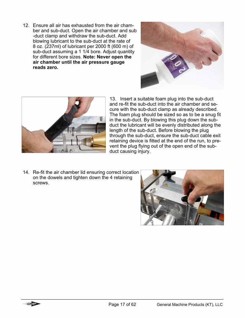
12. Ensure all air has exhausted from the air cham-ber and sub-duct. Open the air chamber and sub-duct clamp and withdraw the sub-duct. Add blowing lubricant to the sub-duct at the rate of 8 oz. (237ml) of lubricant per 2000 ft (600 m) of sub-duct assuming a 1 1/4 bore. Adjust quantity for different bore sizes. Note: Never open the air chamber until the air pressure gauge reads zero.
13. Insert a suitable foam plug into the sub-duct and re-fit the sub-duct into the air chamber and se-cure with the sub-duct clamp as already described. The foam plug should be sized so as to be a snug fit in the sub-duct. By blowing this plug down the sub-duct the lubricant will be evenly distributed along the length of the sub-duct. Before blowing the plug through the sub-duct, ensure the sub-duct cable exit retaining device is fitted at the end of the run, to pre-vent the plug flying out of the open end of the sub-duct causing injury.
14. Re-fit the air chamber lid ensuring correct location on the dowels and tighten down the 4 retaining screws.

Page 18 of 62 General Machine Products (KT), LLC
15. NOTIFY INSTALLATION TEAM
Notify installation team that preparations for lubricating the sub-duct are complete and ready to commence. 16. With the compressor ready to provide air, turn the air valve to the open position.
17. When the foam plug has been expelled from the end or the sub-duct, turn the air valve to the “closed” position and shut down the compressor. Allow the air chamber and sub-duct to exhaust all the com-pressed air. Note: Never open the air chamber un-til the air pressure gauge reads zero.
18. Open the air chamber and remove the cable seal collet plug.

Page 19 of 62 General Machine Products (KT), LLC
6. OPERATING PROCEDURE CABLE BLOWING
1. Position the Cable Blowing Machine in line with the proposed sub-duct.
2. Adjust the mounting frame to the desired height and angle by means of the front frame supports. Withdraw the front “R” clip and retaining pin while supporting the weight of the cable-blowing unit. Raise or lower the blowing unit and locate onto the support bar for the desired position. Refit the retaining pin and “R” clip. Alternatively the blowing unit may be detached from the trolley frame by withdrawing both “R” clips and retaining pins, while supporting the weight of the blowing unit. The blowing unit can then be located in a trench, manhole (depending on size) or at ground level. Ensure the blowing unit is stable and the electronic panel is not immersed in water.
3. If trolley mounted, stabilize the frame on uneven ground by adjusting the height on the piv-oting feet at the rear of the unit and locking in position. Note: Care should be taken when wheeling the trolley around not to catch the ad-justable feet pads on curbs or boulders, this may damage the pivoting foot.
4. Position the cable drum some 20 to 25 ft. (6 to 8 meters) directly behind and in line with the cable blowing machine. (Cable carrying device to be suitably leveled and restrained).
5. Ensure the battery is fully charged before commencement of installation. The battery is charged with the supplied charger thru the jack located on the right of the control panel.
6. Open tractor drive and unscrew retaining knobs on the air chamber.
7. Open the air chamber lid on the pivot bolts.
Clean any de-bris, sludge, dirt, water, lubricant, etc. from the air chamber, frame housing and cable intake guide brack-et assembly each time before use. Lubricate both chains before use. Clean both tractor drive belts before use. Ensure cord seals are intact and not damaged
It is imperative that all persons using, operating or maintaining this cable blowing ma-chine be fully trained and competent and authorized to do so and have read the entire operation manual.
General Machine Products and CBS Products Ltd, CANNOT BE HELD RESPONSIBLE FOR MISUSE OF THIS EQUIPMENT.

Page 20 of 62 General Machine Products (KT), LLC
8. Unscrew the sub-duct clamp retaining bolts.
Refer to the Section 4 “SPECIFICATION” for the correct pressure settings for the relief valve and pressure switch and to Section 6 “MAINTENANCE” for the setting procedures.
NOTE: The cable blowing machine is sup-plied as standard with the pressure relief valve set at 1600 psi (110 bar) and the pressure switch set at 1450 psi (100 bar), these settings are suitable for cables in the range 12 - 32mm O.D. For cables 6 - 12mm O.D. these settings need to be changed, refer to the section 4 “SPECIFICATION” for the correct pressure settings for the relief valve and pressure switch and to section 6 “MAINTENANCE” for the pressure setting pro-cedures.
9. Open the sub-duct clamp on the pivot bolts,
select and fit the correct size cable seal, sub duct seal and sub duct clamp collets for the cable and sub duct being used. (Refer to Tornado configu-ration guide on page 58). Always check and verify the correct size collets are fitted before operating the blowing machine.
10. Place the sub-duct into the sub-duct seal collet and sub-duct clamp collet. Ensure the sub-duct is fully engaged into the sub-duct seal collet.
11. Clamp the sub-duct and tighten the two retaining nuts. Remove the upper cable collet.

Page 21 of 62 General Machine Products (KT), LLC
12. Release the adjusting screw locking ring, turn the adjusting knob until the mark on the air chamber support bracket aligns with the size of the cable to be installed on the increment gauge. Tighten the locking ring to prevent any movement during installation. (Refer to sec-tion 11 for details).
13. Ensure that the sub-duct is fully prepared for use, i.e.
▪ Fully connected ▪ Pressure tested ▪ Cable exit retaining device fitted ▪ Lubricated
For further details on sub-duct lubrication refer to Section 5 14. Open the collet retaining bracket on the pivot bolt.

Page 22 of 62 General Machine Products (KT), LLC
15. Select the correct size cable infeed collet to suit the size of the cable to be installed and secure with the cap screw into each housing. Note: Sealing cord is not required on this
collet.
16. Adjust the height of the intake cable guide bracket to suit the size of the collet and the size of the cable to be installed. To adjust the height, unscrew the locking ring back to the adjusting knob, rotate the ad-justing knob on the underside of the brack-et, align the cable collet size arrow indica-tor for the range of cable collet being used, to the outside diameter (O.D.) cable size to be installed in the same color band for each marker plate i.e. silver to i.e. silver for a 12-16mm cable collet range with a 16mm O.D. cable or blue to blue for a 16-20mm cable collet range with a 16mm O.D. cable. When the correct setting is achieved hold the adjusting screw and turn the locking clock wise to lock in posi-tion and prevent any movement during installation. (Refer to section 11 for de-tails).
17. With the tractor drive unit in its upper position, guide the cable through the infeed guide assembly, tractor drive and feed approximately 6 ft (2 meters) into the sub-duct, by hand.
Always check and verify the correct size collets are fitted before operating the blowing machine.

Page 23 of 62 General Machine Products (KT), LLC
Close the infeed cable guide upper housing and secure with the swing bolt and thumb nut, ensure the cable is correctly located in the bore of the collet.
Close the tractor drive, ensuring the cable is located correctly in the Vee of both upper and lower drive chains. Set the clamping force The correct cable clamping force is vital to the performance of the machine. It should be set
as follows: Tighten the handle with one hand while rotating the clamp washers with the other. The clamp washers will turn easily until the handle begins to clamp them. When the clamp washers become almost impossible to turn with one hand this is the start point for the clamp force setting. Continue to turn the handle a fur-ther 1 full turn. This will ensure the correct cable clamp force.
20. Apply a smear of sili-
cone grease to each seal and install the first cable seal into the groove nearest the tractor drive. Ensure the split of the seal is in the lower half of the air chamber rotat-ed slightly to one side of the vertical, ensure the groove is away from the tractor drive facing the sub-duct.
Note: Ensure that the compressor air supply is never allowed to enter the air chamber or sub-duct when the top tractor drive frame is in the upper position. (i.e. not clamping the cable) and /or the infeed guide bracket is open or not cor-rectly secured. Failure to do so could result in personal injury due to the cable being ejected from the cable blowing machine with high force and velocity.

Page 24 of 62 General Machine Products (KT), LLC
21. Install the second seal into the outer groove with the seal split in the lower half of the air chamber rotated slightly to the other side of the vertical (compared to the first cable seal). Ensure the groove seal lip is away from the tractor drive facing the sub-duct.
22. Fit the upper cable guide collet in po-sition ensuring both seals are located correctly.
23. Re-fit the air chamber lid ensuring cor-rect location on the dowels and tighten down the 4 retaining knobs.
24. The hydraulic control lever is in the “OFF” position.
25. The speed control knob is in the “MIN” position (fully rotated counter-clockwise).
ENSURE THAT:

Page 25 of 62 General Machine Products (KT), LLC
26. The emergency stop button is set. (i.e. in upper po-sition). If not set, twist counter-clockwise to reset.
27. Connect the two hydraulic hoses and the emergency stop cable from the power pack (or hydraulic power source). Never run the blowing machine without the emergency stop cable being connected. NOTE: Only au-thorized, fully trained operators should be allowed to operate the hydraulic power pack (or hydraulic power source).
28. Check the air valve is in the closed position and connect the air supply from the compressor (if not already connected).
NOTE: ENSURE THE AIR VALVE REMAINS IN THE CLOSED POSITION UNTIL REQUIRED.
29. NOTIFY INSTALLATION TEAM Notify installation team that preparations are complete and cable blowing opera-tions are ready to commence.
30. Note: Only authorized, fully trained operators should be allowed to operate the air compressor and the power pack/hydraulic power source. Ensure that both services are available and running and have enough fuel for the duration of the blowing op-eration. Note: the air shut off valve is till in the closed position.
!

Page 26 of 62 General Machine Products (KT), LLC
31. Turn hydraulic valve to “ON” position. 32. Ensure the emergency stop button is in the reset position. (Twist counterclockwise to reset).
33. Press the on/off button. Note: Do not press the RST Button while powering up the counter.
The display will indicate the speed and distance travelled by the cable. To toggle between speed and distance press the SEL (green) button. R displayed on the left side of the screen desig-nates speed (rate). To reset the distance press RST (red) button. Note: It is possible to reset the distance to zero while installing, even if speed is being displayed on the screen.
34. Turn the speed control valve clockwise (towards “MAX”) until the required speed is achieved.

Page 27 of 62 General Machine Products (KT), LLC
35. Continue to install cable into sub-duct. The operator wearing work gloves should hand guide the cable into the blowing machine through a dry clean cloth to prevent any debris on the cable entering the blowing machine and to ensure the cable enters the machine inline with the tractor drive belt without and bending or deviation.
36. When approximately (650 ft.) 200 meters of cable have been installed into the sub-duct or the hy-draulic pressure begins to rise, “open” the air valve slowly to allow the compressed air to enter the air chamber. This assists the installation of the cable through the duct.
37. When the cable has reached its destination, the worker stationed at the other end of the duct will notify the operator to stop the machine by turning the hydraulic valve to the off position.
38. Turn the speed control knob to the “MIN” (counter clockwise) and press the reset button.
39. Turn the air valve to the “closed” position. Allow the air pressure to exhaust. This may take several minutes as there may be a considerable amount of air in the sub-duct. Do not open the air chamber until the air pressure gauge reads Zero.
Note: Care must be taken to avoid injury by clothing or fingers being dragged into the machine. Failure to do so will result personal injury.

Page 28 of 62 General Machine Products (KT), LLC
40. IF THE BLOWING MACHINE STOPS SUDDENLY If the cable blowing machine stops suddenly during the blowing operation it is likely that the pressure switch has tripped stopping the power pack because: A) The cable has reached its destination and the cable exit retaining device has stopped the travel of the cable. B) The cable has become jammed, has hit an obstruction in the duct or the cable blowing operation has reached its maximum capability. C) The power pack has developed a problem or has run out of fuel

Page 29 of 62 General Machine Products (KT), LLC
Push the emergency stop push button. Turn the hydraulic valve to the “off” position.
Turn the speed control knob to “MIN” position (fully counter clockwise)
Press the on/off button to turn the electric’s off.
Turn off the air supply (if required). Correct the problem that caused it to stop.
IN THE EVENT OF AN EMERGENCY

Page 30 of 62 General Machine Products (KT), LLC
1. Ensure the power pack is running 2. Turn the hydraulic valve to the “on” position.
3. Press the power on/off button 4. Turn the air valve to the open position (assuming the required amount of cable in in the duct)
5. Turn the speed control valve towards “MAX” until the required speed is achieved
TO RESTART

Page 31 of 62 General Machine Products (KT), LLC
7. MAINTENANCE To ensure reliable service from your Cable Blowing Machine, we recommend the unit be completely serviced every 6 months AIR CHAMBER The air chamber should be inspected after each oper-ation for seal damage or wear. Seal cord should be replaced if damaged or missing and secured in posi-tion with the adhesive provided. The cable seals should be checked for damage or wear and replaced with new ones if required. ALWAYS apply a smear of silicone grease to the seal bore and lip when installing the seal on to a cable. ALWAYS clean out any debris in the air chamber. TRACTOR DRIVE Inspect the chain drive blocks for wear each week. CHECK the chain tension weekly and adjust if necessary with the two ex-ternal adjustment screws. (Do not over tension) the chain should slightly lift off the chain guides, when pulled at the center by finger. THE CHAIN SHOULD BE LUBRICATED EACH TIME USED by applica-tion of Metaflux spray grease 70-88. This is achieved by running the cable blowing machine at about 150 ft/min (45m/min) without any cable or applied air and carefully inserting the spray tube from the canister into the red painted holes on the operator side of the aluminum drive castings (2). The spray tube should be carefully inserted until the chain can just be felt and then withdrawn about 7/8 to 1 inch (20 - 25mm) and spraying for approximately 1 second. Do not over lubricate, as this may lead to the drive belts being contaminated with lubri-cant. If contamination does result, wipe the belts clean thoroughly before attempting any blowing operation. Do not use harsh solvents. (This is based on normal use where the chains are not exposed to excessive contamination).
Seal Cord Locations

Page 32 of 62 General Machine Products (KT), LLC
GENERAL The machine should be stored under cover when not in use. The machine should be wiped clean after each time used. ALWAYS ensure that there are sufficient cable seals, cord seal, cord adhesive and silicone grease available in the toolbox to cover the next installation. ALWAYS ensure that the battery is fully charged, before the cable blowing machine is to be used. Note: The battery is not charged by the power pack. The machine uses a conventional gel cell battery and is charged through the Battery Charger Connection (see below). CHECK the tire pressures and condition weekly. Oil the frame pivot
points monthly and lubricate the Oilite bearings with light machine oil every month. Apply grease to the jacking screw thread each month. Clean out any dirt/debris from the cable-measuring wheel, measuring disc and speed pick up probe. Oil air chamber adjusting screw and cable infeed guide adjusting screw monthly. Grease axles every month. Check function of electrical panel each time. SERVICE CONNECTIONS CHECK the condition of the hydraulic hoses each time they’re used and replace if worn or damaged. CHECK the condition of the emergency stop cable each time it’s used and replace if worn or damaged. CHECK the condition of the compressed air hose each time and replace if worn or damaged.
Charging the 12 volt battery before use: Plug in the supplied battery charger in the charging jack found on the right of the control panel. Initially charge the battery for 8 hours before use (to approximately 13 volts). Continuous charging of the battery with your charger will reduce the life of the battery. Remove the charger when charging is complete. When voltage dips to 12 volts, recharge the battery. Optimize battery life by turning off the display when not in use.

Page 33 of 62 General Machine Products (KT), LLC
PROCEDURE FOR SETTING THE RELIEF VALVE AND PRESSURE SWITCH FOR CABLE SIZES .24-.47 inch (6-12mm) OD When installing small diameter cables with “soft/flexible” characteristics, it will be necessary to reduce the pressure relief valve and pressure switch settings to help prevent the cable from buckling or being jammed in the air chamber mounted collet. The pressure relief valve should be set to 1015 psi (70 bar). The pressure switch should be set to 870 psi (60 bar). For “softer/more flexible” cables the above values may have to be reduced proportionally to ena-ble successful installation. TO SET PRESSURE RELIEF VALVE FOR SMALL DIAMETER, .47 INCH OD (12MM) OR UNDER OR FLEXIBLE CABLE Clamp a piece of 1” O.D. dowel/round bar x 13” long in the drive belts so it butts up to the air chamber mounted collets (in effect placing the motors in stall mode). Note: The below procedure will put the unit in a hydraulic by-pass condition and will rapidly heat the oil. Try to keep the time in bypass to a minimum as the heated oil could change your readings. 1. Connect the hydraulic hoses and start the power pack. With the electric control panel
switched “off”, turn hydraulic on/off valve to the “on” position. 2. Rotate the speed control knob fully clockwise to “MAX” and observe pressure gauge read-
ing of approximately 1600 psi (110 bar). 3. Loosen the 1/2” lock nut and adjust pressure relief valve (see fig. 1) using a 5/32” Hex
wrench until the pressure gauge pointer drops to 1015 psi (70 bar). 4. Rotate the speed control knob counter-clockwise (towards “MIN”) until the pressure gauge
reads 0 psi (0 bar). 5. Rotate the speed control knob again, fully clockwise to “MAX” and re-check pressure
gauge reading of approximately 1015 psi (70 bar). 6. Re-adjust the relief valve slightly if needed until 1015 psi (70 bar) is indicated on the
gauge. Finally tighten the lock nut while preventing the relief valve adjustment from turn-ing.
7. Rotate the speed control knob again, fully clockwise to “MAX” and re-check the pressure reading of approximately 1015 psi (70 bar) after lock nut is tightened. If different, readjust.
Lock Nut
Adjusting Screw
Fig1
Pressure Relief Valve

Page 34 of 62 General Machine Products (KT), LLC
TO SET PRESSURE SWITCH FOR SMALL DIAMETER .47 INCH OD (12MM) OR UNDER OR FLEXIBLE CABLE Clamp a piece of 1” O.D. dowel/round bar x 13” long between top and bottom housings so it butts up to the air chamber mounted collets (in effect placing the motors in stall mode). Note: The be-low procedure will put the unit in a hydraulic by-pass condition and will rapidly heat the oil. Try to keep the time in bypass to a minimum as the heated oil could change the readings 1. Connect the electric lead to the power pack and blowing machine. 2. Rotate the speed control knob fully counter-clockwise to “MIN”. 3. Press the on/off button (to turn the electric’s on). 4. Turn the pressure switch adjusting screw fully in (clockwise) using a 1/8 inch Hex key
through the hole in the front of the panel (see fig. 2). 5. Start the power pack. 6. Turn the hydraulic on/off valve to “on” position. 7. Turn the speed control knob towards “max” (clockwise) until the pressure gauge reads 870
psi (60 bar). 8. Turn the pressure switch adjusting screw slowly out (counter-clockwise) until the power
pack stops. 9. Turn the speed control knob to minimum (turned fully counter-clockwise). 10. After 5 seconds has elapsed restart the power pack and turn the speed control knob slow-
ly towards ”MAX” and note what pressure the power pack stops, repeat the procedure and fine adjust the pressure switch adjusting screw until 870 psi (60 bar) is achieved.
When installation of cables of diameters .47inch (12mm) O.D. and above are re-quired again, reset the pressure relief valve and pressure switch to: Pressure relief valve 1600 psi (110 bar) Pressure switch 1450 psi (100 bar)
Pressure Switch Fig 2
Note:

Page 35 of 62 General Machine Products (KT), LLC
PROCEDURE DAILY WEEKLY MONTHLY
Clean all assemblies and components thoroughly
Inspect hydraulic hoses for leaks and cracks
Inspect fasteners, screws and retaining pins / wire
Check / adjust chain tension
Check tractor drive pads for wear / damage
Clean air chamber
Check / replace cord seals
Check / replace cable seals
Tire pressure / condition
Check condition of emergency stop lead
Clean rod infeed guide bracket and collets
Clean measuring wheel measuring disc and speed pick up probe
Function of electronic panel
Oil the frame pivot points
Grease jacking screw thread
Oil air chamber adjusting screw
Oil Oilite bearings with light machine oil
Grease mounting frame axles
Clean and lubricate chain*
Clean and lubricate the chain support slide bars
Check the condition of service and spare 12V DC battery
Check condition of the compressed air hose
7.1. MAINTENANCE SCHEDULE
* Should be more often if subjected to abnormal use and / or excessive contamination.

Page 36 of 62 General Machine Products (KT), LLC
PROBLEM SOLUTION
Tractor feed does not pull the cable off the drum
Assist the drum by turning it or pulling the ca-ble off the drum by hand.
The Cable Blowing Machine stops. Hydraulic pressure gauge reads zero.
Machine has tripped out on pressure switch, cable has hit an obstruction or become jammed. Turn hydraulic valve to off position. Turn speed control knob to “MIN”. If cable is jammed try restarting the Cable Blowing Machine. If this fails it may be necessary to pull the cable out a short distance and start again. Investigate obstruction in duct. If all else fails it may be necessary to remove the sub-duct and remake the bad connection.
It is difficult to keep the cable moving near the end of a duct run
Assist the Cable Blowing Machine by manual-ly pushing the cable into the tractor drive. DO NOT BEND OR CRIMP THE CABLE.
The cable is hard to re-start having stopped
Put air to the system with the cable clamped between the upper and lower drive chains. The tractor feed can be restarted after the air pressure has increased and stabilized. If the cable cannot be restarted, this may be due to the weight of cable in the sub-duct, it will be necessary to pull the cable out and restart the installation with the full air pressure applied.
7.2. TYPICAL PROBLEMS EXPERIENCED WHEN CABLE BLOWING:

Page 37 of 62 General Machine Products (KT), LLC
PART No. DESCRIPTION Location 36292 5/32" T-Handle Hex Wrench 1 32604 Battery Tester 2 34444 1/8" T-Handle Hex Wrench 3 89142 3mm Hex Key 4 89143 4mm Hex Key 5 89144 5mm Hex Key 6 89145 6mm Hex Key 7 89147 3mm dia O-Ring Cord 10 ft. 8 89148 Silicone Grease Dow Corning 7 100gr Tube 9 89588 Sealing Cord Glue 10 89153 Chain Lubrication Spray 11 89150 Pliers 6” 12 87096 Screwdriver 6” (slot) 13 89146 13-17mm Open Ended Wrench 14 32616 1 x 13 Wooden Dowel 15 32617 1/2 Combination Wrench 16 32485 Charging Transformer 17 32486 Power Cord 18
Tornado Tool Kit
4 5 6 7
8
9
10
11
12
13
14 15
16
17
18
2
3
1

Page 38 of 62 General Machine Products (KT), LLC
8. PROCEDURE FOR REPLACEMENT OF CHAIN DRIVES Tools required: 6mm Hex Key 13mm Wrench Ensure the hydraulic hoses to the power pack are disconnected from the blowing ma-chine before carrying out this procedure.
1. Remove the hydraulic motor from the top frame using 6mm Hex Key. Do not discon-nect hydraulic hoses connected to the motor.
2. Remove the stop washer on the bottom of the main jacking screw using a 6 mm Hex key.
3. Unscrew the main clamping screw and separate the top and the bottom of the push-er unit. Place in a safe location.
4. On the lower unit, slacken the 2 chain ad-justers using a 13mm wrench.
5. Remove the swing bolt from the side of unit using a 13mm wrench.
6. Pull the tensioner pin out from the sprocket assembly. Remove spacer from other side.

Page 39 of 62 General Machine Products (KT), LLC
7. Remove the tension sprocket assembly 8. Remove the chain-connecting link.
9. Remove the chain. 10. Check the chain support slide bars for wear. Clean and relubricate.
11. Pass the pre-lubricated new chain around the drive sprocket. Feed the chain along the unit and reconnect the chain-connecting link. Remember to install the 2 center connecting link plates.
12. Align the tension sprocket with the chain and locate into position. Insert the tension pin through the tension sprocket. Place the ten-sion pin spacer on the tension pin through the opposite hole. Refit swing bolts using a 13mm wrench. Adjust the chain evenly via the swing bolts, checking free rotation of the chain. Do not over tighten the chain.
Replace the chain in the top housing using the same steps that are used above for the bot-tom housing.

Page 40 of 62 General Machine Products (KT), LLC
Reassembling the top and the bottom parts of the pusher unit.▪ ▪ Refit the main clamping screw. ▪ Replace the stop washer on the bottom of the main jacking screw using a 6mm Hex key. ▪ Replace the hydraulic motor using the 6mm Hex key. Adjust top chain, do not over tighten
chain.

Page 41 of 62 General Machine Products (KT), LLC
9. PROCEDURE FOR REPLACEMENT OF CABLE COLLETS Ensure the air supply is disconnected from the blowing machine before carrying out this procedure.
Tools Required 4mm Hex Key
Step 1 Collet Removal ▪ Ensure that the air valve is closed and the air pressure is at zero. ▪ Open the air chamber to expose the collets. ▪ Remove the socket head cap screw (2) using a 4mm
Hex key and remove the collet (2)
Step 2 Collet Refitting ▪ Select the replacement collets (refer to appendix 5 for collet information) ▪ Clean the air chamber with a dry cloth. ▪ Fit the appropriate collets and secure with a socket head cap screw using a 4mm Hex key.
The collet with horizontal O-ring grooves is fitted into air chamber base. ▪ Re-new any worn or damaged radial cord seals and always renew both air chamber split
cord seals. Ensure there is sufficient cord to butt up to the sub-duct and the cable seal.
Note: Correct fitting of the cord seals is a major factor in air leakage from the air chamber.
▪ Close the air chamber.
NOTE: The main seals in the air chamber consist of a 3mm cord seal, which is cut to the correct length and permanently fixed with adhesive.

Page 42 of 62 General Machine Products (KT), LLC
10. PROCEDURE FOR REPLACEMENT OF SUB-DUCT COLLETS Ensure the air supply is disconnected from the blowing machine before carrying out this procedure. Always check and verify the correct size collets are fitted before operating the blowing machine. SUB-DUCT CLAMP COLLETS Tools Required 4mm Hex Key Step 1 Collet Removal Open the sub-duct clamp. Remove the socket head cap screws (2) using a 4mm Hex
key and remove the collet (2).
Step 2 Collet Refitting Select he replacement collets (refer to Appendix 6 for collet information) Clean the sub-duct clamp with a dry cloth. Fit the required collets and secure with a socket head cap screws using a 4mm Hex key. Close the sub-duct clamp. SUB-DUCT SEAL COLLETS Tools Required 4mm Hex Key Step 1 Collet Removal Ensure that the air valve is closed and the air pressure
gauge is at zero. Open the air chamber to expose the collets. Remove the socket head cap screw (2) using a 4mm Hex key. Step 2 Collet Refitting Select the collets (refer to Appendix 6 for collet information). Clean air chamber with a dry cloth. Fit the replacement collets and secure with a socket head cap screw using a 4mm Hex
key. Re-new any worn or damaged radial cord seals always renew both air chamber split cord
seals. Note: Correct fitting of the cord seals is a major factor in air leakage from the air cham-ber. Close the air chamber. Note: The main seals in the air chamber consist of a 3mm cord seal, which is cut to the correct length and permanently fixed with adhesive.
Page 43 of 62 General Machine Products (KT), LLC
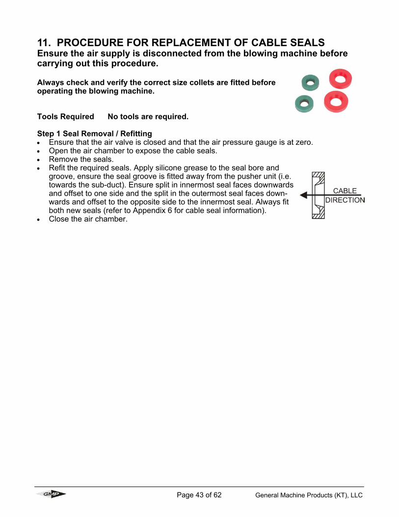
11. PROCEDURE FOR REPLACEMENT OF CABLE SEALS Ensure the air supply is disconnected from the blowing machine before carrying out this procedure. Always check and verify the correct size collets are fitted before operating the blowing machine. Tools Required No tools are required. Step 1 Seal Removal / Refitting Ensure that the air valve is closed and that the air pressure gauge is at zero. Open the air chamber to expose the cable seals. Remove the seals. Refit the required seals. Apply silicone grease to the seal bore and
groove, ensure the seal groove is fitted away from the pusher unit (i.e. towards the sub-duct). Ensure split in innermost seal faces downwards and offset to one side and the split in the outermost seal faces down-wards and offset to the opposite side to the innermost seal. Always fit both new seals (refer to Appendix 6 for cable seal information).
Close the air chamber.

Page 44 of 62 General Machine Products (KT), LLC
12. PROCEDURE FOR THE AIR CHAMBER AND COLLET TYPE CABLE INFEED CABLE GUIDE ASSEMBLY HEIGHT Step 1 When changing collets and seals to accept smaller / larger sizes of cable it is necessary to adjust the height of the air chamber and the collet type infeed guide assembly. This setting must be carried out accurately, as failure to do so will seriously impair the function of the machine. AIR CHAMBER: To adjust the air chamber bracket in either direction, release the
adjusting knob locking ring and turn the knob placed directly under the air chamber. Down for smaller OD cables, and up for larger OD cables.
Select the adjustment required using the increment gauge on the side of the unit.
Tighten the locking ring to prevent any movement during installation.
CABLE INFEED GUIDE ASSEMBLY: To adjust the collet type cable infeed guide assembly brack-
et in either direction, release the adjusting knob locking ring and turn the knob placed directly under the infeed guide bracket, down for smaller OD cables, and up for larger OD cables.
Select the adjustment required using the increment gauges on the side of the infeed cable guide bracket. Align the cable collet size arrow indicator for the range of ca-ble collet being used, to the outside diameter (OD) cable size to be installed in the same color band for each marker plate i.e. silver to silver for a 12-16mm cable collet range with a 16mm OD cable. Or blue to blue for a 16-20mm cable collet range with a 16mm OD cable.
Tighten the locking ring to prevent any movement during installation.

Page 45 of 62 General Machine Products (KT), LLC
13. ALIGNMENT OF AIR CHAMBER TO THE CABLE PUSHER UNIT 1. Insert a round parallel bar between the top and bottom cable
pusher housings and clamp down. Ensure the rod doesn't inter-fere with metering wheel and that it passes through he air cham-ber. (See picture).
2. Refer to Section 11.0 Procedure for adjusting the air chamber and infeed guide assembly height and the height of the air chamber. Adjust the air chamber such that the top face of the lower housing is inline with the centre line of the rod.
3. The lateral alignment of the air chamber needs to be checked adjusted. The objective is to position the air chamber such that the center line of the rod is parallel with the center line of the air chamber, adjustment is made by slackening the four socket cap screws that secure the air chamber to the support bracket (see picture). When the alignment is correct re-tighten the four socket cap screws.

Page 46 of 62 General Machine Products (KT), LLC
14. MONTHLY SERVICE – CHECK LIST 1. Remove the drive chains from the pusher unit. Check both of the chains for excessive
wear. Replace, if required and lubricate with the spray grease provided. 2. Remove any debris from the housings. 3. Check the chain supports slide bars for excessive wear and lubricate with the spray
grease provided. Replace, if required. 4. Check all other moving parts e.g. bearings, shafts, sprockets etc. . and lubricate. 5. Check main jacking screw . and lubricate. 6. Check all hydraulic fittings and check for leaks. 7. Check the hydraulic hoses for external damage. 8. Check the electrical lead for external damage. 9. Check the electrical plug and sockets. 10. Check the function of the electronic control module. 11. Check the operation of the emergency stop button. 12. Check condition of cable seals and cord seals in the air chamber. 13. Check the operation of the cable measuring device. 14. Check the wheel tire pressures and free rotation. Inflate and lubricate, as necessary. 15. Clean the infeed cable guide bracket. 16. Complete service history record.

Page 47 of 62 General Machine Products (KT), LLC
Service no Date Carried out by Record of service/repair
15. SERVICE HISTORY RECORD

Page 48 of 62 General Machine Products (KT), LLC
16. TROUBLESHOOTING GUIDE
Initial starting hydraulic pressure at the point of starting a cable installation the hydrau-lic pressure must be between 290 - 580 psi (20-40 bar). If not, do not continue. See the below sections “Will Not Achieve Max Pressure” and “Runs At Higher Than Ex-pected Pressure” to rectify the problem before commencing cable installation. WILL NOT ACHIEVE MAX PRESSURE • Hydraulic control valve not open fully • Speed control not positioned fully • Faulty power pack (check performance) • Jacking screw not tight enough (producing belt slip) • Worn pads due to cable slip • Excessive lubrication of chains (on to pads causing belt slip) RUNS AT HIGHER THEN EXPECTED PRESSURE • Chains too tight / excessive clamping force. • Poor lubrication • Seized chain links • Over tightening of jacking screw • Misalignment of air chamber slider • Cable drum not rotating freely • Misalignment of entry guide • Poor duct, installation / friction • Insufficient out-put from compressor • Incorrect seal/collet fitted • Dirt / debris in pusher housings CABLE BLOWING MACHINE STOPS SUDDENLY DURING CABLE INSTALLATION • Max pressure achieved • Obstacle in duct installation • Power Pack out of fuel • Emergency button pressed • Damaged lead between Power Pack and blowing machine ENGINE DOES NOT STOP AT MAX PRESSURE • Emergency lead not connected • Electrical control panel not switched on • Battery low on power • Pressure switch unplugged • Fuse blown in control panel

Page 49 of 62 General Machine Products (KT), LLC
EXCESSIVE AIR LEAKAGE FROM AIR CHAMBER • Damaged cord seal • Cable seals worn, incorrect size, wrong way round, misalignment of air chamber bracket in
relation to cable diameter • Incorrect collets COUNTER NOT READING OR GIVING INCORRECT READINGS • Battery low on power • Counter program has been changed - clear program and re-program as described on page
60

Page 50 of 62 General Machine Products (KT), LLC
Part No Description Qty Required
89140 Tornado Belt Orange 2
32294 Motor Hydraulic 32 cc 2
89147 Seal Cord (cut to length as required) 10 ft.
89148 Silicon Grease 1 tube
89588 Silicon Cord Glue 1 tube
89156 Wheel Blower Pneumatic 2
89151 Wheel Blower Solid 2
34471 Wheel Blower w/Metal Hub 2
89153 Lubricant Chain Spray 1 can
31727 Chain Support Slide Bar 1
32512 Battery 12 V DC 1
32216 Bearing Belt Drive 4
32217 Circlip - ExternaI 20mm 4
89401 Bolt Swing F/Clamp Housing 2
28883 Thumb Nut Cap 2
28882 Thumb Nut 2
32307 Seloc Pin M6X24 2
17. RECOMMENDED SPARE PARTS

Page 51 of 62 General Machine Products (KT), LLC
LAYOUT OF CABLE BLOWING MACHINE
1 Cable Pusher 2 Air Chamber 3 Sub-Duct Clamp 4 Cable infeed bracket assembly 5 Unit Lifting Point 6 Hydraulic Control Panel 7 Electronic Control Panel 8 Air “Open / Close” Valve
9 Air Hose Connection 10 Hydraulic Hose Connection (at rear of unit) 11 Emergency stop socket (on side of unit) 12 Frame Leveling Foot 13 Tool Box 14 Mounting Frame 15 Tractor Drive Movement Indicator 16 12 Volt Battery Access door (under unit)
Appendix 1
4
12 11
10
5 1
15
2
3
8
9
6
14
7
13 16

Page 52 of 62 General Machine Products (KT), LLC
Appendix 2

Page 53 of 62 General Machine Products (KT), LLC
Appendix 3
Air Compressor
Power Pack
Compressed Air Hose Connected to Cable Blowing
Machine
Hydraulic Hose Connections Power Pack to Cable Blowing
Machine
Cable Blowing Machine
Emergency Stop Cable Power Pack to Cable
Blowing Machine Fiber Optic
Cable Cable Drum
Sub Duct
CABLE BLOWING MACHINE SERVICE CONNECTIONS

Page 54 of 62 General Machine Products (KT), LLC
1 Air Pressure Gauge 2 Hydraulic Pressure Gauge 3 Speed Control Knob 4 Hydraulic “On / Off” Lever 5 Power “On / Off” Button 6 Emergency Stop Button 7 Length / Speed Digital Display 8 Hydraulic Control Panel 9 Electronic Control Panel
HYDRAULIC AND ELECTRONIC CONTROL PANEL LAYOUT
2 8 5 9
6
7
4 3
1
Appendix 4

Page 55 of 62 General Machine Products (KT), LLC
How to specify the collets and seals to match your cable and duct size . 1. Select one (1) Duct Clamp (locator A) that represents the size of the duct that you're using. 2. Select one (1) Duct Seal (locator B) that represents the size of the duct that you're using. 3. Select the Cable Collet (locator C). Always use a Cable Collet on the cable exit side.
If you use either 6-9 mm or 9-12 mm cable, use a Cable Guide (locator D) on the cable in feed side, for anything larger than these sizes, use a Cable Collet on the in feed side.
4. Select the Cable Seals (locator E) that match your cable size. 5. Select one (1) Cable Seal Plug (locator F) that match your cable size.
A
B
C E Exit Side In Feed Side
Let our "Cable Blowing Experts" tailor your configuration. Call our Hotline at 1-800-345-6009 for any questions. Locator Description Qty needed
(A) Duct Clamp 1 (2 halves) (B) Duct Seal 1 (2 halves) (C) Cable Collet 1 or 2 (2 halves) see note 3 (D) Cable Guide 0 or 1 (2 halves) see note 3 (E) Cable Seals 1 (pkg of 10) (F) Cable Seal Plug 1 unit
In order to configure your Tornado to work with your specific cable requirements you must select items below that match your duct and cable size at additional charge
89021 DUCT CLAMP 1" 89041 DUCT CLAMP 1.25" 89061 DUCT CLAMP 1.50" 89071 DUCT CLAMP 2"
(Loc A) DUCT CLAMPS (O.D. Controled) 89033 DUCT CLAMP 3/4”
(Loc C & D) CABLE COLLETS (6-28 MM) & GUIDES (6-12 MM) 89081 6-9 MM (.23 - .35") (1 Collet REQ) (exit side) Collet & guide used together
for this size cable 89082 6-9 MM (.23 - .35") (1 Guide REQ) (in feed side)
89083 9-12 MM (.35 - .47") (1 Collet REQ) (exit side) Collet & guide used together for this size cable 89084 9-12 MM (.35 - .47") (1 Guide REQ) (in feed side)
89091 12-16 MM (.47 - .63") (2 Collets REQ) 89092 16-20 MM (.63 - .79") (2 Collets REQ) 89101 20-24 MM (.79 - .95") (2 Collets REQ) 89102 24-28 MM (.95 - 1.10") (2 Collets REQ)
Same collet used on both in feed and exit side
89022 DUCT SEAL 1" 89042 DUCT SEAL 1.25" 89062 DUCT SEAL 1.50" 89072 DUCT SEAL 2"
(Loc B) DUCT SEALS (O.D. Controled) 89034 DUCT SEAL 3/4”
Tornado Configuration Guide
D C or
Appendix 5
89125 6-7.5 MM (.23 - .29") 89126 7.5-9 MM (.29 - .35") 89127 9-10.5 MM (.35 - .41") 89128 10.5-12 MM (.41 - .47") 89129 12-14 MM (.47 - .55") 89130 14-16 MM (.55 - .63") 89131 16-18 MM (.63 - .71") 89132 18-20 MM (.71 - .79") 89133 20-22 MM (.79 - .87") 89134 22-24 MM (87 - .94") 89135 24-26 MM (.94 - 1.02") 89136 26-28 MM (1.02 - 1.10")
(Loc F) CABLE SEAL PLUGS (6-28 MM)
89162 28-30 MM (1.10 - 1.18") 89164 30-32 MM (1.18 - 1.26")
89085 6-7.5 MM (.23 - .29") 10/PK 89086 7.5-9 MM (.29 - .35") 10/PK 89087 9-10.5 MM (.35 - .41") 10/PK 89088 10.5-12 MM (.41 - .47") 10/PK 89093 12-14 MM (.47 - .55") 10/PK 89094 14-16 MM (.55 - .63") 10/PK 89095 16-18 MM (.63 - .71") 10/PK 89096 18-20 MM (.71 - .79") 10/PK 89103 20-22 MM (.79 - .87") 10/PK 89104 22-24 MM (.87 - .95") 10/PK 89105 24-26 MM (.95 - 1.02") 10/PK 89106 26-28 MM (1.02 - 1.10") 10/PK
(Loc E) CABLE SEALS (6-28 MM)
89110 28-30 MM (1.10 - 1.18") 10 PK 89111 30-32 MM (1.18 - 1.26") 10 PK
ID COLOR CODES GREEN 1 LINE
GREEN 2 LINES PURPLE 1 LINE
PURPLE 2 LINES SILVER 1 LINE
SILVER 2 LINES GOLD 1 LINE
GOLD 2 LINES BLUE 1 LINE
BLUE 2 LINES RED 1 LINE
RED 2 LINES BLACK 1 LINE
BLACK 2 LINES

Page 56 of 62 General Machine Products (KT), LLC
Notes:

Page 57 of 62 General Machine Products (KT), LLC
The device must be wired and installed into the machine prior to programming. Tornado is fitted with C-M-DEV-CUB5R, reflective version The DIP switch positions are as follows:
1 OFF 2 OFF 3 OFF 4 OFF
Please see the attached CUB5 Program-ming Overview attached to this document. • Press and hold SEL for 2 seconds to enter programming mode • Enter the Pro-Code 222 by pressing RST to change numbers and SEL to skip
to the next number. • Once correct Press and Hold SEL for 2 seconds • Pro-no should now be flashing, press RST • Press RST to move through the various sections 1-input, 2-rate 3-display,
sections 4 and 5 will be unavailable, see the next page of instructions for the parameters required.
• Press SEL to enter that section • To change the value of a parameter press RST • Press SEL to move to the next parameter (You will have to hold for 2 seconds
on certain parameters). • When all the parameters in the section have been scrolled through you will
return to the Pro-no display, press RST to scroll to another section else press SEL to exit programming mode.
Programming Parameters for CUB5R Counter/rate Meter Serial Numbers 0315 Onwards
Appendix 6

Page 58 of 62 General Machine Products (KT), LLC
First reset the current settings to Factory Settings on the counter: Scroll to 3-DSPLAY
Skip through the parameters until FACT SET is displayed. Change this to YES by pressing RST PRO NO should be displayed, Press SEL.
Continue to re-program the Counter by pressing and holding SEL to re-enter programming mode. Pro-no will be displayed, press RST to move through the relevant sections. The following parameters are required for the Tornado counter: Press RST Once: Counter Parameters (1-INPUT)
INPA-B = Cnt ud - if correct press SEL. CNT A DP = 0 - if correct press SEL. CNT A SCF = 0.01 (Metric, m) or 0.0328 (Imperial, ft) - once
correct press & Hold SEL. CNT A RST = TO ZERO - if correct press SEL. CNT A DIR = NOR - if correct press SEL. CNT B LD = 0 - once correct press & Hold SEL. CNT B BAT = NO - if correct press SEL. RST P-UP = NO - if correct press SEL. USER INP = NO - if correct press SEL.
Press RST Twice: Rate Parameters (2-RATE)
RATE ENB = YES - if correct press SEL. RATE DP = 0 - if correct press SEL. RATE DSP = 60 - once correct press & Hold SEL. RATE INP = 100 (Metric, m/min) or 30.5 (Imperial, ft/min)-
once correct press & Hold SEL. LO-UDT = 1.0 - if correct press SEL. HI-UDT = 2.0 - if correct press SEL.
Press RST Three times: DISPLAY (3-DSPLAY)
SEL ENB = YES - if correct press SEL. RST ENB = YES - if correct press SEL. D-SCROLL = NO - if correct press SEL. PRO CODE = 222 - CODE REQUIRED TO RE-PROGRAM -
once correct press & Hold SEL. FACT SET = NO - Press SEL Twice

Page 59 of 62 General Machine Products (KT), LLC
CUB5 PROGRAMMING QUICK OVERVIEW

Page 60 of 62 General Machine Products (KT), LLC
Appendix 7 TORNADO W/MANIFOLD LESS POWER PACK
The modified Tornado Cable Blowing Machine is designed to be used with an alternative hydraulic power source in lieu of the standard Tornado Power Pack. The unit is equipped with an external flow and pressure control manifold, which effectively regulates the hydraulic power source as high as 12 gpm (45 l/m) and 3000 psi (207 bar) to the required 4 gpm (15 l/m) at 1700 psi (117 bar) . The manifold is fitted with 3/8" hydraulic quick release couplings. The power source must be connected to manifold's inlet and outlet with two detachable hoses via the quick release cou-pling. (Fig1)
Inlet Parker P/N FF-371-8FP
Outlet Parker P/N FF-372-8FP
Fig 1
GMP P/N 89007
Important: The Tornado Emergency Stop Accessory Kit (GMP P/N 29003), is required with an alternative power source in order to be connected with Tornado’s emergency stop circuit. Note: The cartridges are factory set. Do not tamper nor adjust.
!

Page 61 of 62 General Machine Products (KT), LLC
Emergency Stop Kit P/N 29003
The kit is designed to connect the gasoline engine of an alternative hydraulic power source with the emergency stop circuit of the GMP P/N 89007 Tornado with manifold less power pack. The kit consists of: • Emergency Stop Terminal Box includes M4 screws and
lock washers • Armored Cable 26 ft. (8m) with connectors • ScotchLok® inline splice connector • Wire (brown) 5 ft. (1.5m) with spade connector Installation procedure: • Mount the emergency stop terminal box to the hydraulic unit in an accessible location. • Connect the terminal box's black wire (with ring terminal) to the hydraulic unit frame for
grounding. Remove powder coating or paint if required. • Connect engine's stop switch wire with the brown wire via the ScotchLok® connector. • Connect terminal box's red wire (with spade male connector) to the female spade con-
nector of the brown wire. • Connect engine’s stop circuit to the emergency stop terminal box via the armored cable. • Verify that the circuit is wired properly. Ensure that when the emergency stop button is
depressed on the Tornado’s control panel that the engine stops.
Wiring Schematic
Connect to hot end of engine stop switch
Connect to chassis ground
Emergency Stop Terminal Box

Page 62 of 62 General Machine Products (KT), LLC
GMP • 3111 Old Lincoln Hwy • Trevose, PA 19053 • USA TEL: +1-215-357-5500 • FAX: +1-215-357-6216 • EMAIL: [email protected]