DESIGN OF SOFTWARE ARCHITECTURE Instructor: Dr. Hany H. Ammar Dept. of Computer Science and...
169
DESIGN OF SOFTWARE ARCHITECTURE Instructor: Dr. Hany H. Ammar Dept. of Computer Science and Electrical Engineering, WVU 1
-
Upload
harold-bond -
Category
Documents
-
view
225 -
download
1
Transcript of DESIGN OF SOFTWARE ARCHITECTURE Instructor: Dr. Hany H. Ammar Dept. of Computer Science and...
DESIGN OFSOFTWARE ARCHITECTURE
Instructor: Dr. Hany H. Ammar
Dept. of Computer Science and Electrical Engineering, WVU
1
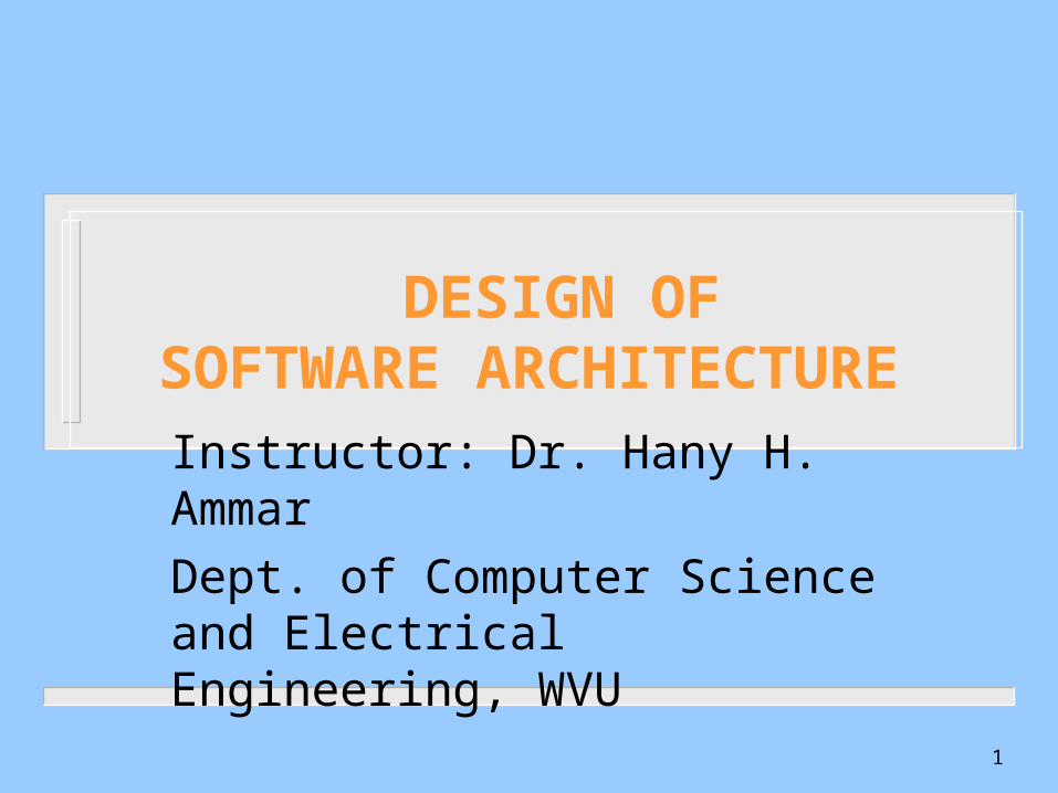
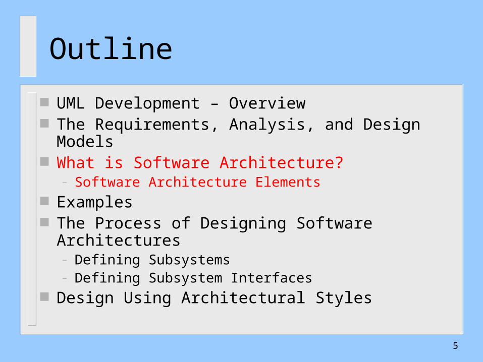
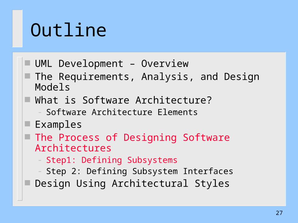
Outline UML Development – Overview The Requirements, Analysis, and Design Models What is Software Architecture?
– Software Architecture Elements Examples The Process of Designing Software Architectures
– Defining Subsystems– Defining Subsystem Interfaces
Design Using Architectural Styles – Software Architecture Styles– The Attribute Driven Design (ADD)
2
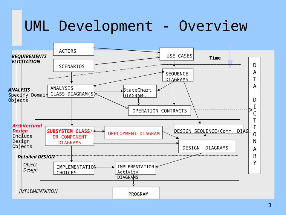
UML Development - Overview
PROGRAM
ACTORS
ANALYSISSpecify Domain Objects
Detailed DESIGN
IMPLEMENTATION
DATA
DICTION
ARY
TimeUSE CASES
ANALYSISCLASS DIAGRAM(S)
IMPLEMENTATIONActivity DIAGRAMS
SEQUENCEDIAGRAMS
OPERATION CONTRACTS
StateChart DIAGRAMs
DEPLOYMENT DIAGRAMSUBSYSTEM CLASS/OR COMPONENT
DIAGRAMS
Architectural DesignIncludeDesign Objects
ObjectDesign
SCENARIOS
REQUIREMENTSELICITATION
DESIGN DIAGRAMS
IMPLEMENTATIONCHOICES
DESIGN SEQUENCE/Comm DIAG.
3

The Requirements, Analysis, and Design Models
Static Analysis Dynamic Analysis
Functional/ NonfunctionalRequirements
Use Case Diagrams/Sequence Diagrams(the system level)
- Analysis Class Diagrams- State Diagrams/Refined Sequence Diagrams (The object level)
Requirements ElicitationProcess
The AnalysisProcess
Static ArchitecturalDesign
Dynamic Design
The DesignProcess
• Design Class Diagrams andComponents Diagrams• Design Sequence/• Collaboration Diagrams4
Outline
UML Development – Overview The Requirements, Analysis, and Design Models What is Software Architecture?
– Software Architecture Elements Examples The Process of Designing Software Architectures
– Defining Subsystems– Defining Subsystem Interfaces
Design Using Architectural Styles
5
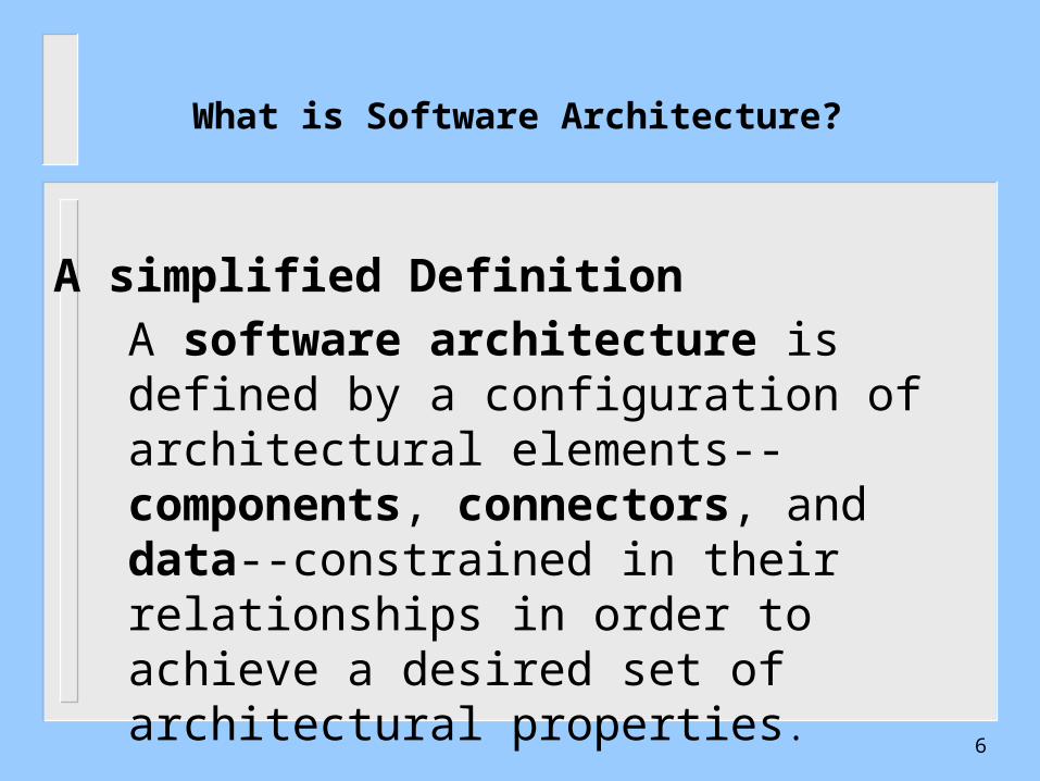
What is Software Architecture?
A simplified Definition
A software architecture is defined by a configuration of architectural elements--components, connectors, and data--constrained in their relationships in order to achieve a desired set of architectural properties.
6
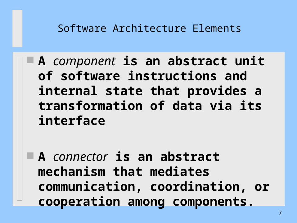
Software Architecture Elements
A component is an abstract unit of software instructions and internal state that provides a transformation of data via its interface
A connector is an abstract mechanism that mediates communication, coordination, or cooperation among components.
7
Software Architecture Elements
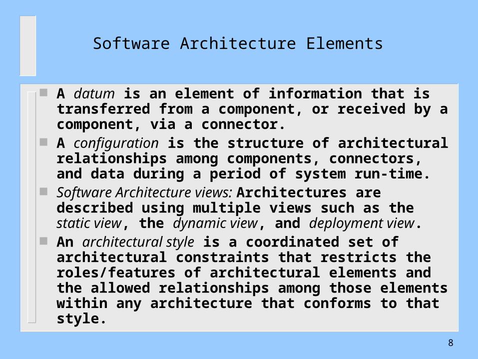
A datum is an element of information that is transferred from a component, or received by a component, via a connector.
A configuration is the structure of architectural relationships among components, connectors, and data during a period of system run-time.
Software Architecture views: Architectures are described using multiple views such as the static view, the dynamic view, and deployment view.
An architectural style is a coordinated set of architectural constraints that restricts the roles/features of architectural elements and the allowed relationships among those elements within any architecture that conforms to that style.
8
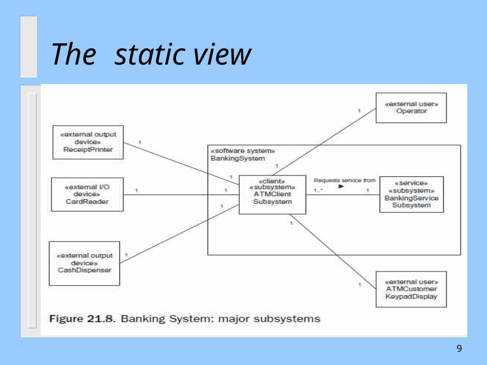
The static view
9
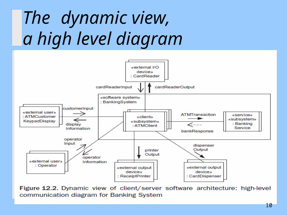
The dynamic view, a high level diagram
10
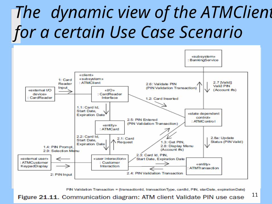
The dynamic view of the ATMClient for a certain Use Case Scenario
11
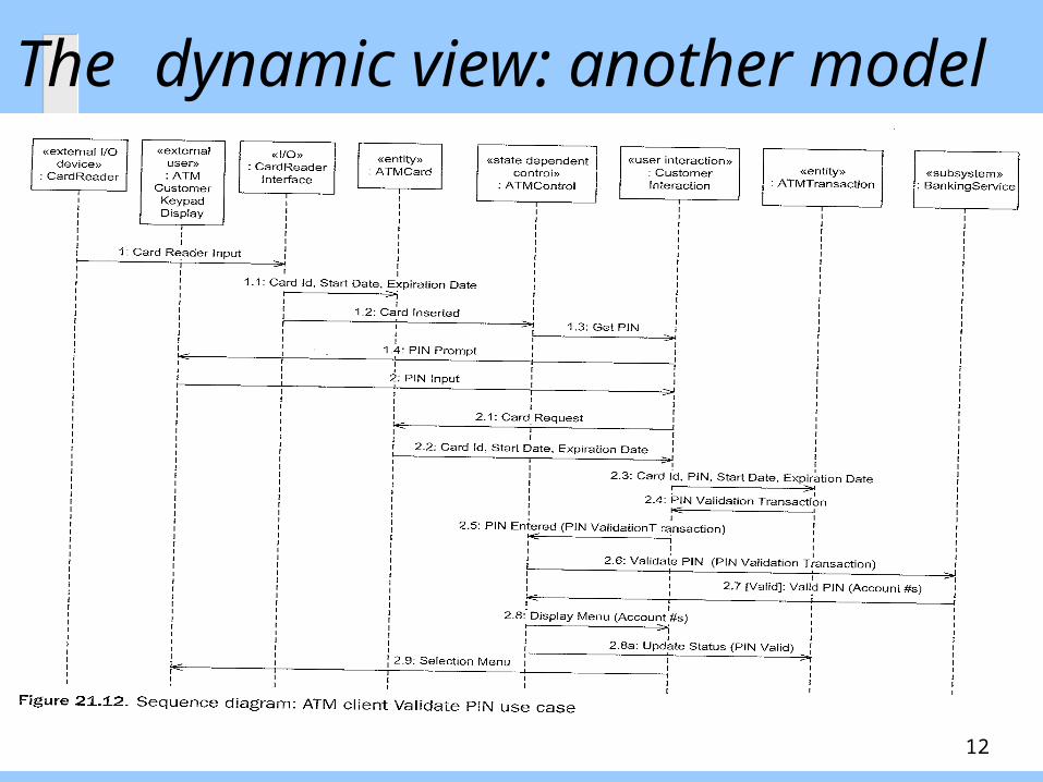
The dynamic view: another model
12
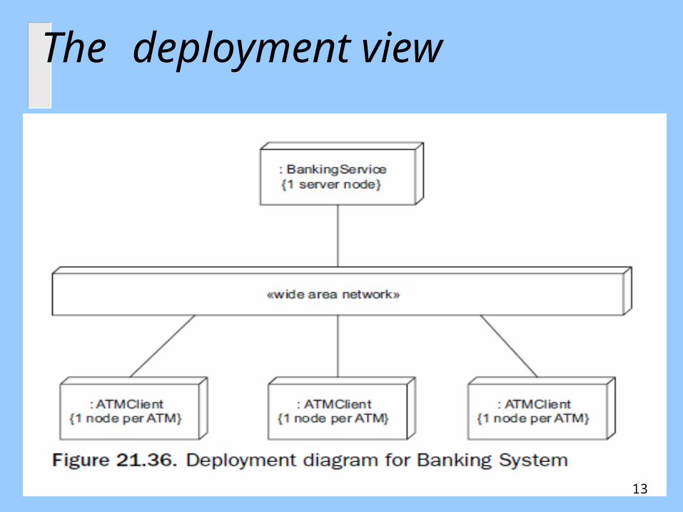
The deployment view
13

Introducing Architecture StylesMore details on architecture styles to be discussed later
The Layered Architecture
e.g Network
Services
Architecture
14

Network Services ArchitectureDeployment view
15
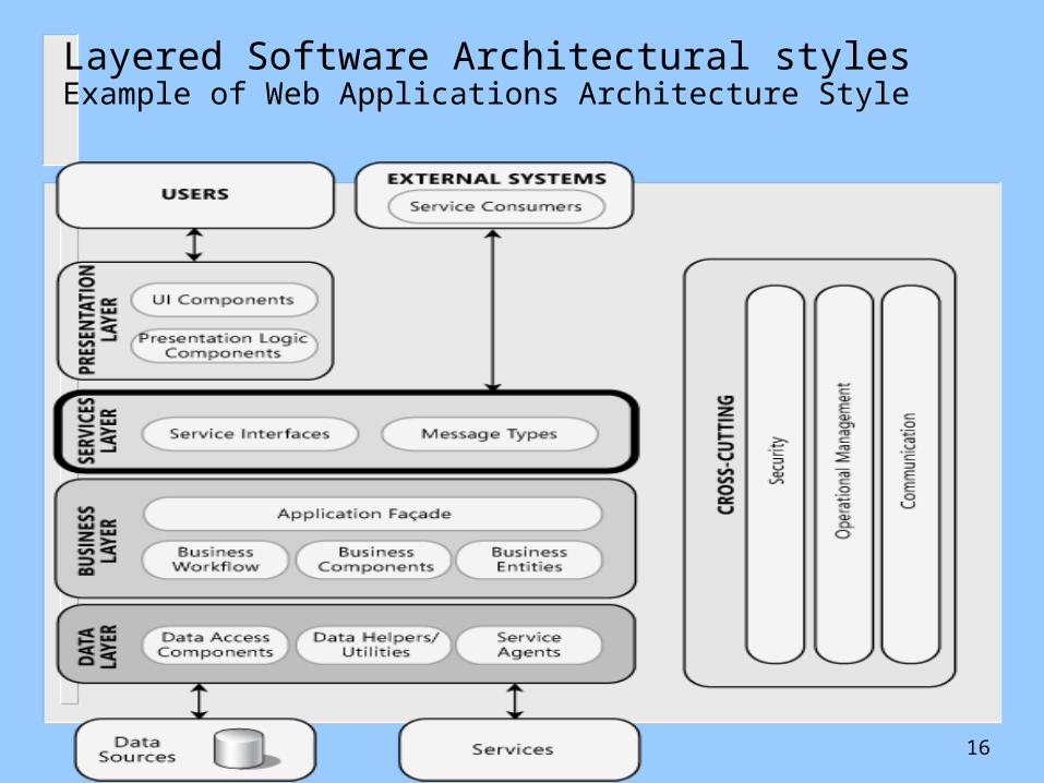
Layered Software Architectural stylesExample of Web Applications Architecture Style
16
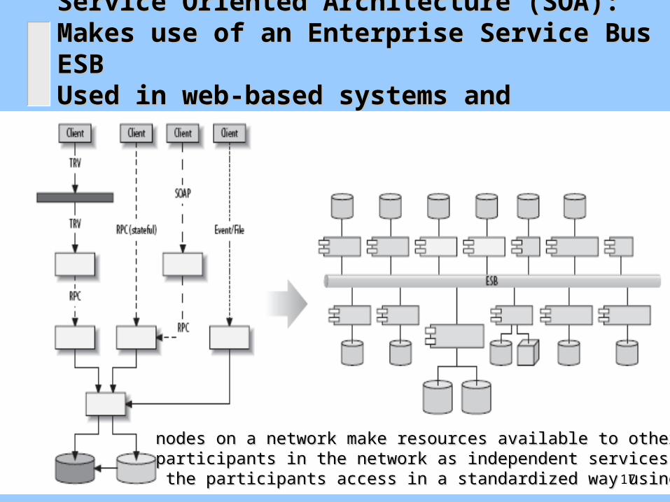
Service Oriented Architecture (SOA): Service Oriented Architecture (SOA): Makes use of an Enterprise Service Bus ESBMakes use of an Enterprise Service Bus ESBUsed in web-based systems and distributed computingUsed in web-based systems and distributed computing
nodes on a network make resources available to other nodes on a network make resources available to other participants in the network as independent services thatparticipants in the network as independent services that the participants access in a standardized way using the ESBthe participants access in a standardized way using the ESB17
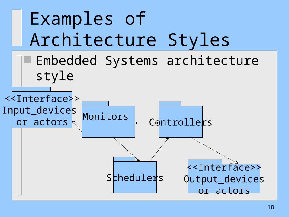
Examples of Architecture Styles
Embedded Systems architecture style
Monitors
<<Interface>>Input_devices
or actors Controllers
<<Interface>>Output_devices
or actorsSchedulers
18
Outline
UML Development – Overview The Requirements, Analysis, and Design Models What is Software Architecture?
– Software Architecture Elements Examples The Process of Designing Software Architectures
– Defining Subsystems– Defining Subsystem Interfaces
Design Using Architectural Styles
19
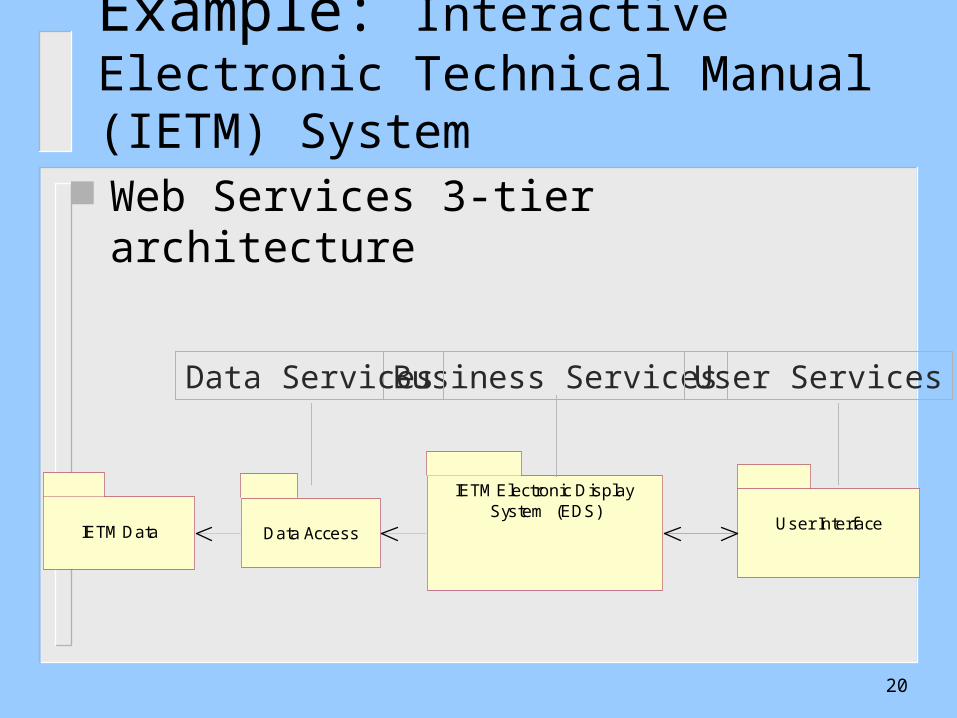
Example: Interactive Electronic Technical Manual (IETM) System
Web Services 3-tier architecture
Data Access
IETM Electronic Display System (EDS)
IETM Data User Interface
Business Services User ServicesData Services
20
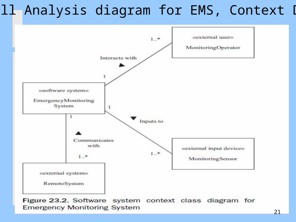
Recall Analysis diagram for EMS, Context Diag.
21
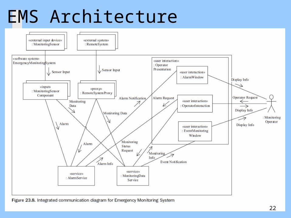
EMS Architecture
22
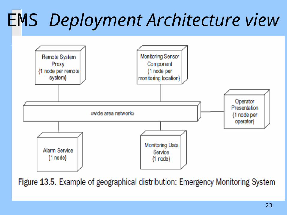
EMS Deployment Architecture view
23
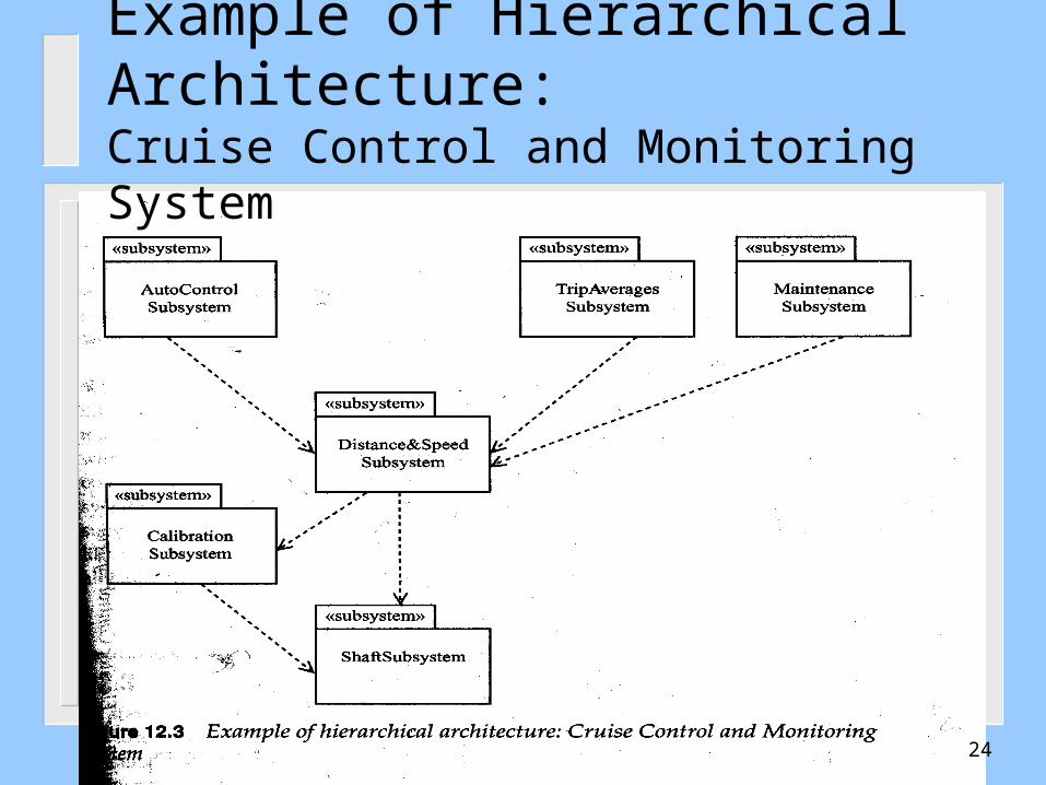
Example of Hierarchical Architecture:Cruise Control and Monitoring System
24
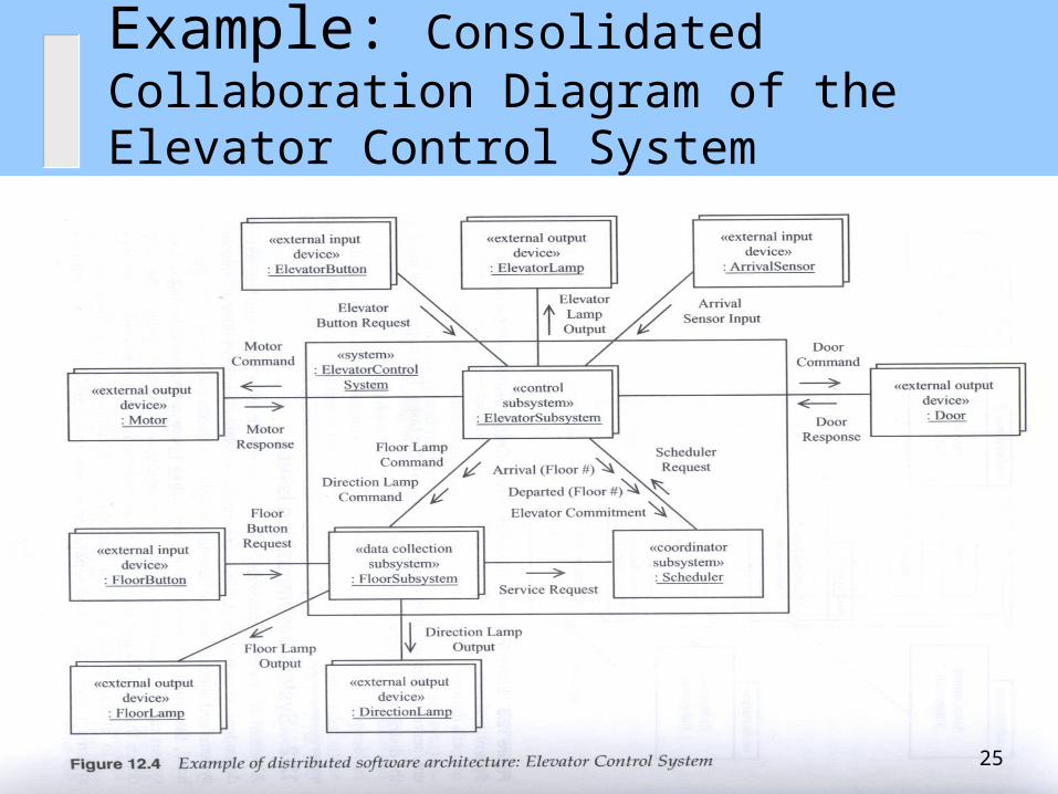
Example: Consolidated Collaboration Diagram of the Elevator Control System
25

Online Shopping System: Structured Classes with Ports
26
Outline
UML Development – Overview The Requirements, Analysis, and Design Models What is Software Architecture?
– Software Architecture Elements Examples The Process of Designing Software Architectures
– Step1: Defining Subsystems– Step 2: Defining Subsystem Interfaces
Design Using Architectural Styles
27

Information Available At Architectural Design The Requirements model
– Use cases, Use case Diagram, system sequence diagrams
The Analysis model– Analysis class diagram, – stateCharts for multi-modal classes, and – Domain Object sequence diagrams
28
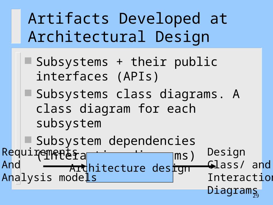
Artifacts Developed at Architectural Design
Subsystems + their public interfaces (APIs) Subsystems class diagrams. A class
diagram for each subsystem Subsystem dependencies (interaction
diagrams)
Architecture design
RequirementsAndAnalysis models
DesignClass/ and InteractionDiagrams
29
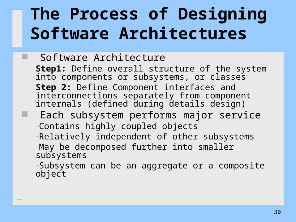
The Process of Designing Software Architectures
Software Architecture Step1: Define overall structure of the system into components or subsystems, or classesStep 2: Define Component interfaces and interconnections separately from component internals (defined during details design)
Each subsystem performs major service –Contains highly coupled objects–Relatively independent of other subsystems –May be decomposed further into smaller subsystems–Subsystem can be an aggregate or a composite object
30
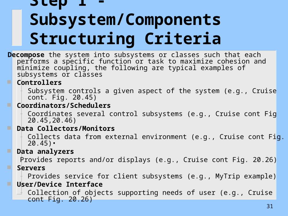
Step 1 - Subsystem/Components Structuring Criteria
Decompose the system into subsystems or classes such that each performs a specific function or task to maximize cohesion and minimize coupling, the following are typical examples of subsystems or classes
Controllers – Subsystem controls a given aspect of the system (e.g., Cruise cont. Fig. 20.45)
Coordinators/Schedulers – Coordinates several control subsystems (e.g., Cruise cont Fig 20.45,20.46)
Data Collectors/Monitors – Collects data from external environment (e.g., Cruise cont Fig. 20.45)•
Data analyzersProvides reports and/or displays (e.g., Cruise cont Fig. 20.26)
Servers– Provides service for client subsystems (e.g., MyTrip example)
User/Device Interface– Collection of objects supporting needs of user (e.g., Cruise cont Fig. 20.26)
31
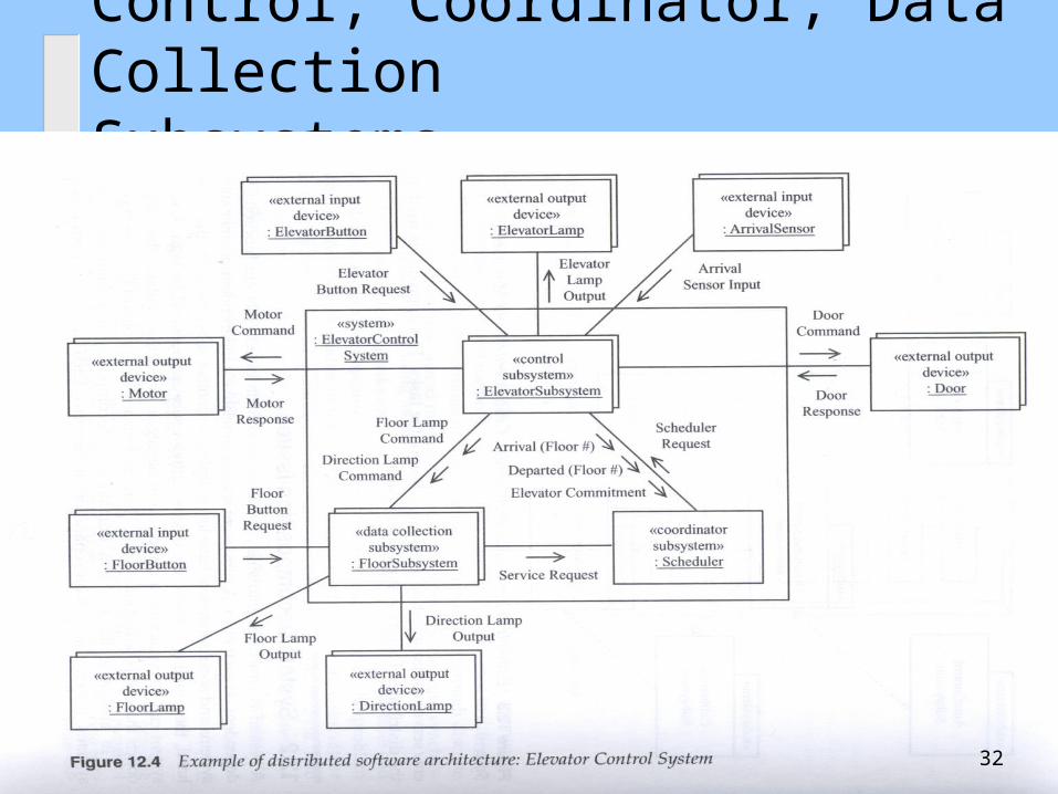
Control, Coordinator, Data CollectionSubsystems
32
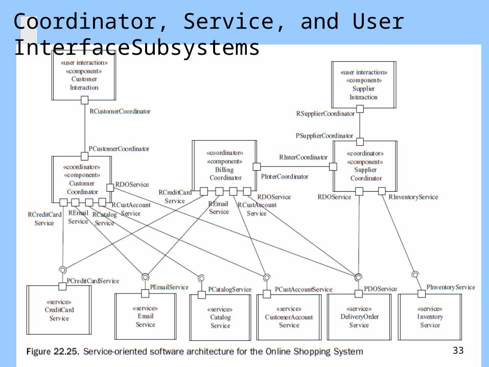
Coordinator, Service, and User InterfaceSubsystems
33

Service subsystems, Input & User Interface
34
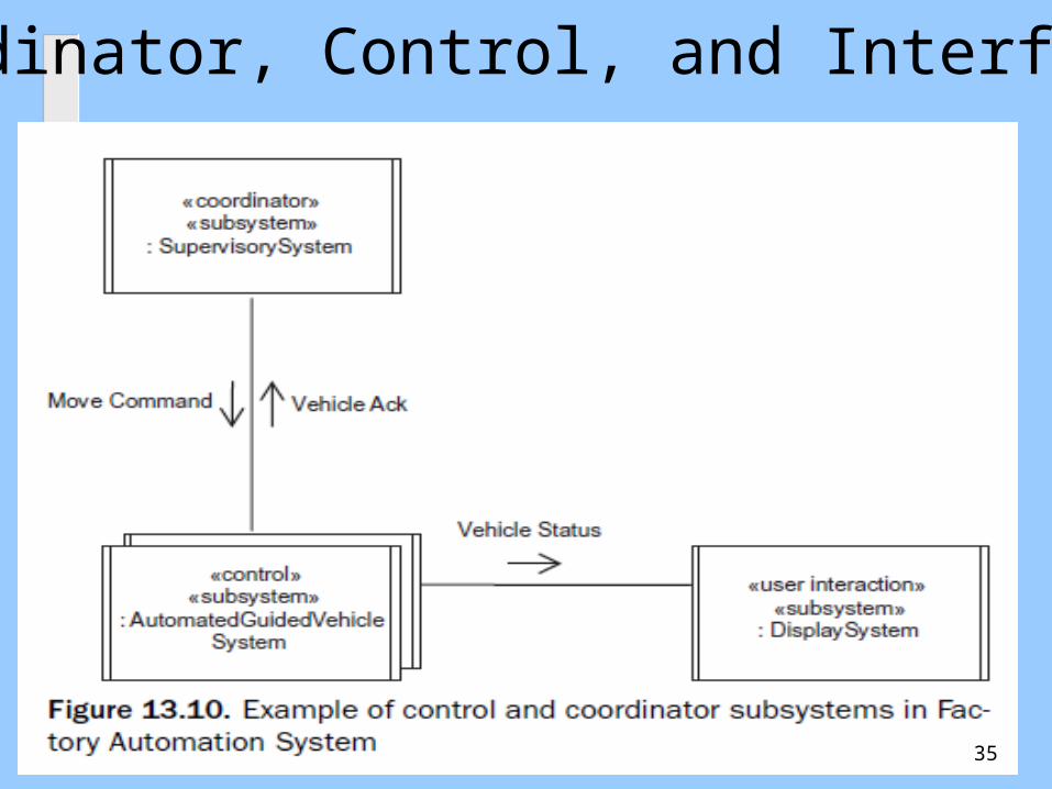
Coordinator, Control, and Interface
35
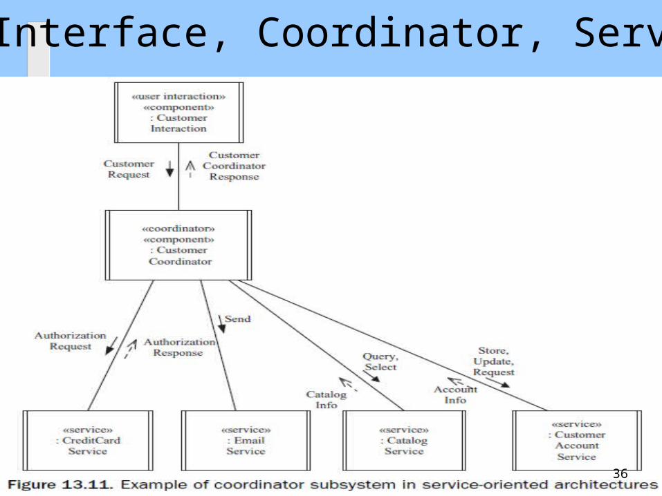
User Interface, Coordinator, Service
36

Another way of forming subsystems
Aggregate into the same subsystem– Objects that participate in the same use case
(functional cohesion)– Objects that have a large volume of interactions
(e,g, Control object & objects it controls) or share common data or file structures (communicational cohesion)
– Object that execute in the same time (temporal cohesion)
37
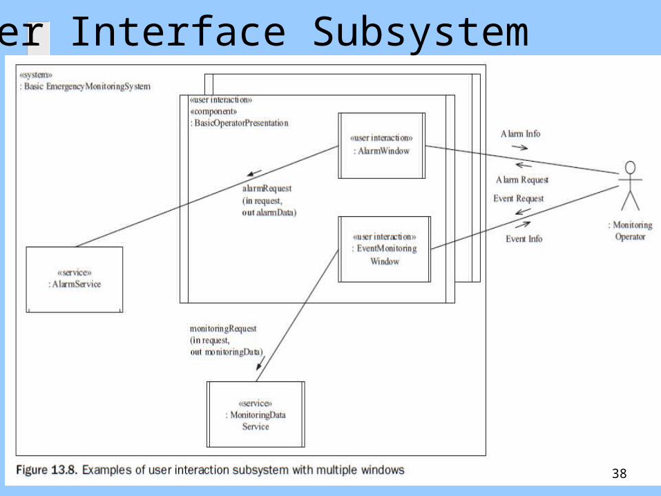
User Interface Subsystem
38
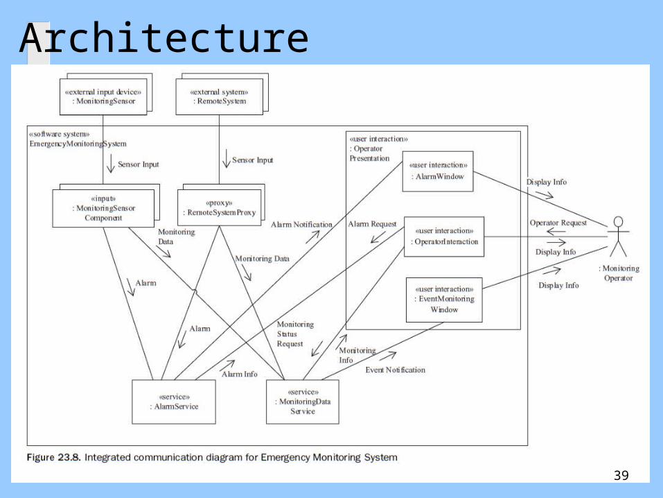
Architecture
39
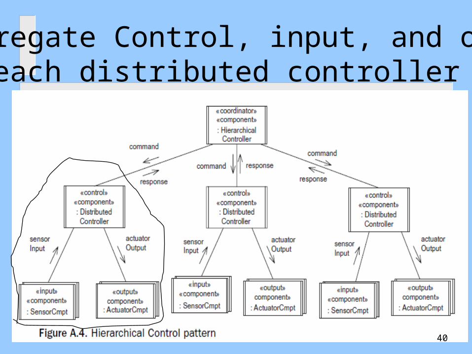
Aggregate Control, input, and outputof each distributed controller
40
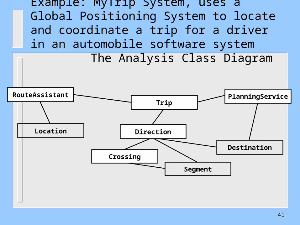
Example: MyTrip System, uses a Global Positioning System to locate and coordinate a trip for a driver in an automobile software system
The Analysis Class Diagram
Location
Segment
Crossing
Direction
Destination
TripRouteAssistant PlanningService
41

Design Class DiagramMyTrip Subsystems
Location
Segment
Crossing
Direction
Destination
RoutingSubsystem PlanningSubsystem
TripRouteAssistant PlanningService
42
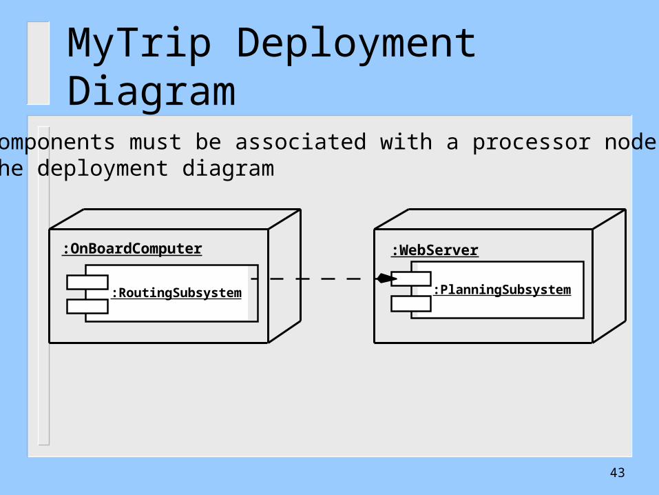
MyTrip Deployment Diagram
:RoutingSubsystem :PlanningSubsystem
:OnBoardComputer :WebServer
Components must be associated with a processor node in the deployment diagram
43

New Classes and Subsystems
TripLocation
PlanningService
SegmentCrossing
RouteAssistant
Direction
Destination
TripProxy
SegmentProxy
PlanningSubsystem
Message
Connection
CommunicationSubsystem
RoutingSubsystem
44
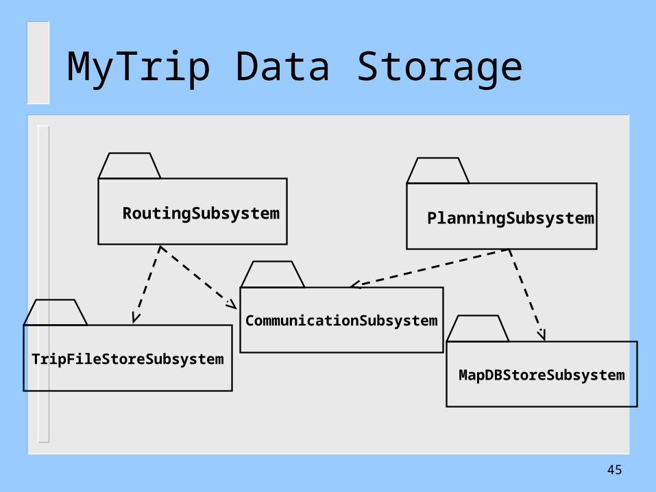
MyTrip Data Storage
PlanningSubsystem
MapDBStoreSubsystemTripFileStoreSubsystem
RoutingSubsystem
CommunicationSubsystem
45
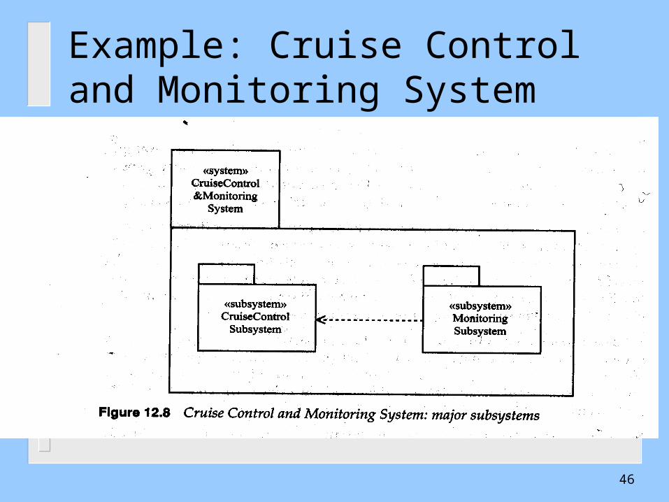
Example: Cruise Control and Monitoring System
46
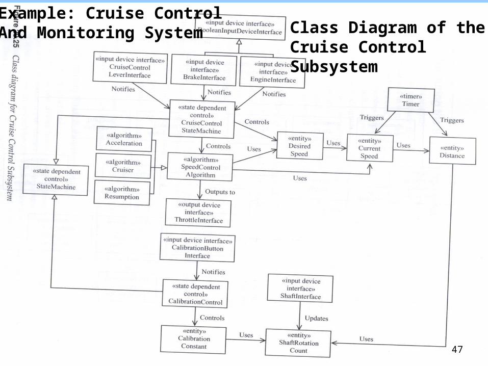
Example: Cruise Control And Monitoring System Class Diagram of the
Cruise Control Subsystem
47
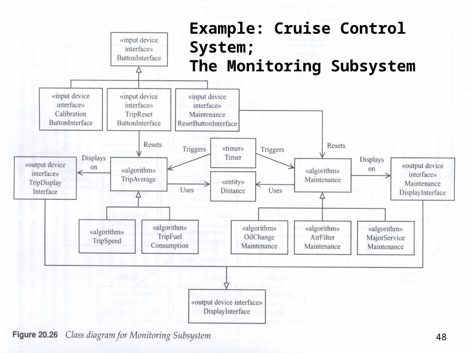
Example: Cruise Control System;The Monitoring Subsystem
48

Example: Aggregating classes into a subsystem using temporal cohesion
49
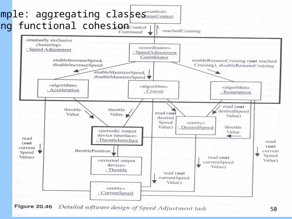
Example: aggregating classesUsing functional cohesion
50
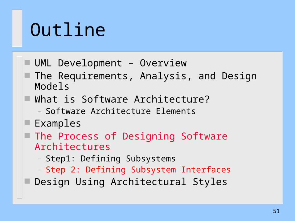
Outline
UML Development – Overview The Requirements, Analysis, and Design Models What is Software Architecture?
– Software Architecture Elements Examples The Process of Designing Software Architectures
– Step1: Defining Subsystems– Step 2: Defining Subsystem Interfaces
Design Using Architectural Styles
51
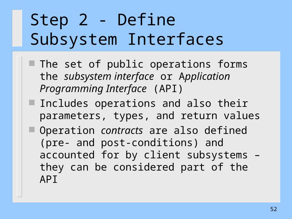
Step 2 - Define Subsystem Interfaces
The set of public operations forms the subsystem interface or Application Programming Interface (API)
Includes operations and also their parameters, types, and return values
Operation contracts are also defined (pre- and post-conditions) and accounted for by client subsystems – they can be considered part of the API
52
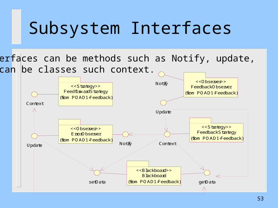
Subsystem Interfaces
FeedforwardStrategy
(from POAD1-Feedback)
<<Strategy>> FeedbackObserver<<Observer>>
(from POAD1-Feedback)
FeedbackStrategy<<Strategy>>
(from POAD1-Feedback)ErrorObserver<<Observer>>
(from POAD1-Feedback)
Blackboard<<Blackboard>>
(from POAD1-Feedback)
Context
Update Notify Context
Update
Notify
setData getData
Interfaces can be methods such as Notify, update, Or can be classes such context.
53
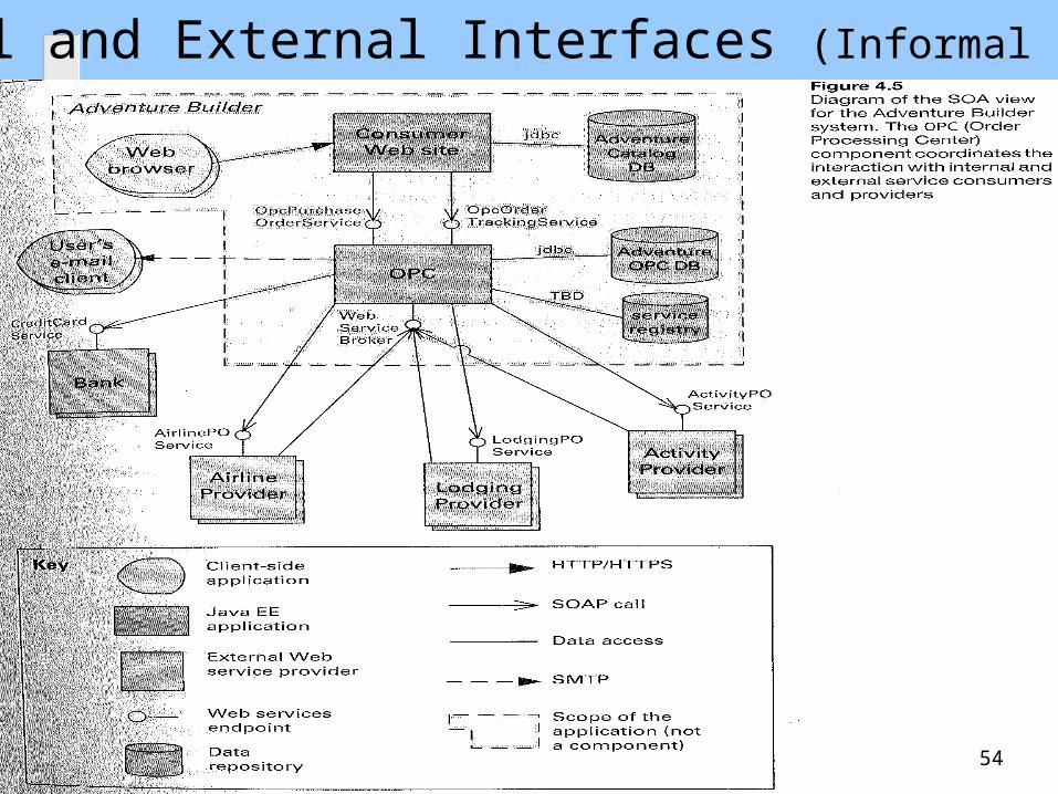
Internal and External Interfaces (Informal Notation)
54
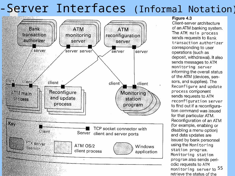
Client-Server Interfaces (Informal Notation)
55

Client-Server Interfaces (Informal Notation)
56
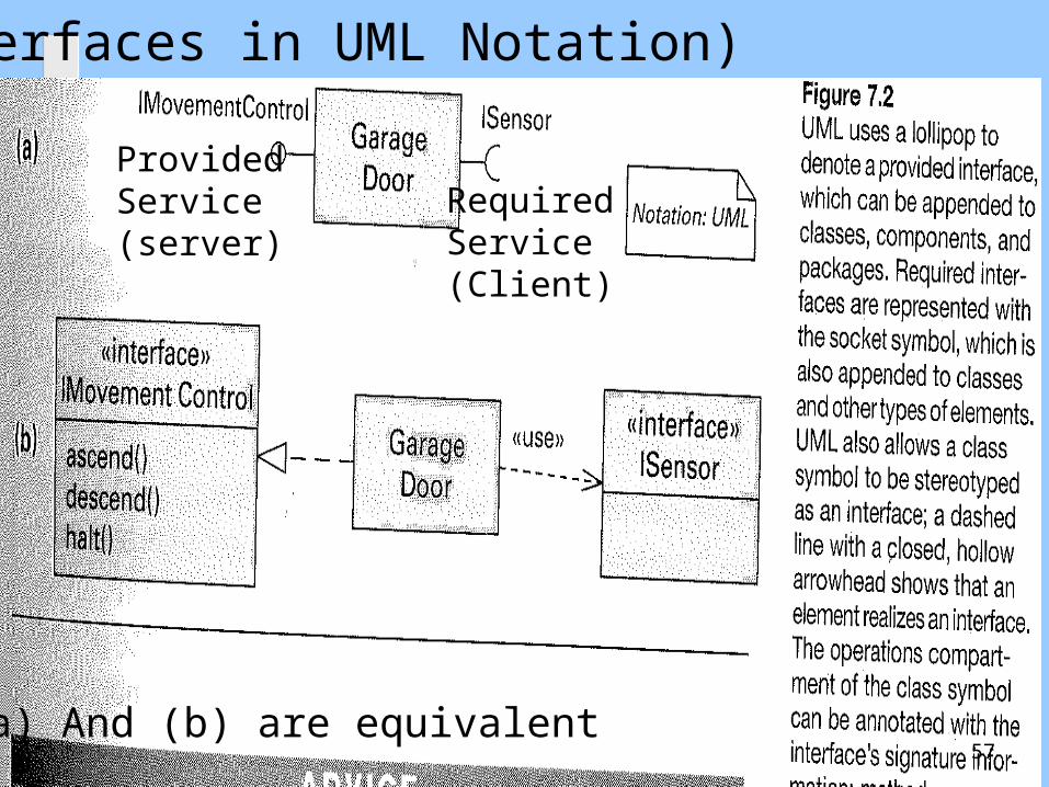
(a) And (b) are equivalent
ProvidedService(server)
RequiredService(Client)
Interfaces in UML Notation)
57
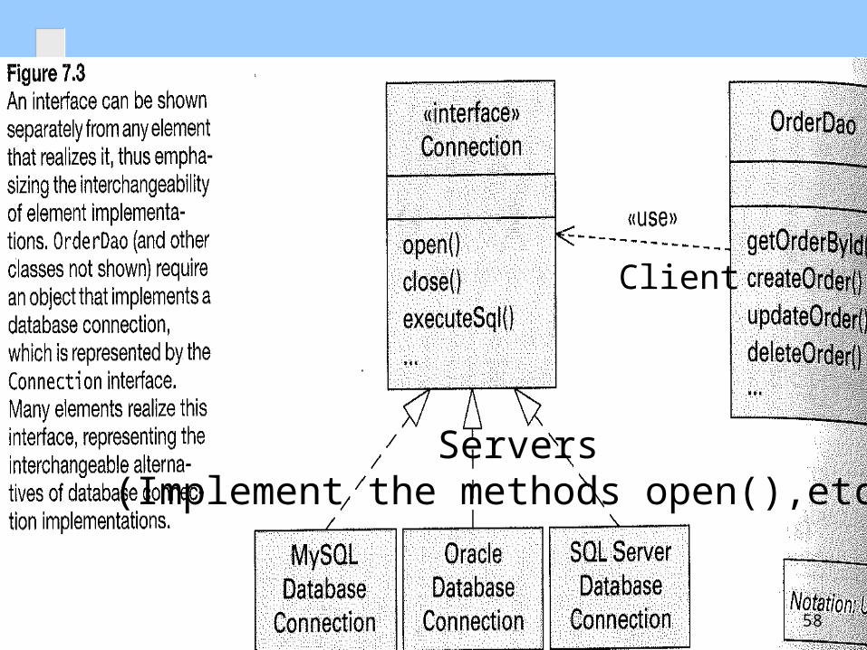
Client
Servers(Implement the methods open(),etc.)
58
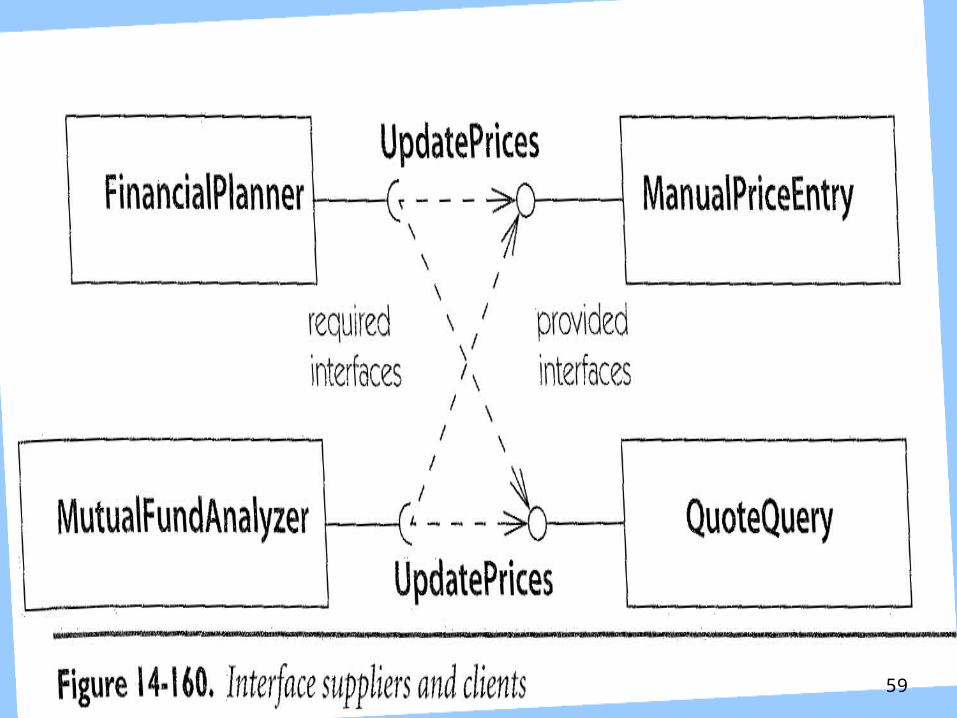
59
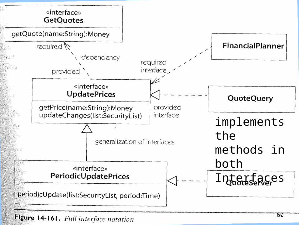
implements themethods in bothInterfaces
60
Example: A Digital Sound RecorderFrom Requirements-to-Analysis-to-Design
The main function of the DSR is to record and playback speech.
The messages are recorded using a built-in microphone and they are stored in a digital memory.
The DSR contains an alarm clock with a calendar. The user can set a daily alarm. The alarm beeps until the user presses a key, or after 60 seconds.
61

Digital Sound Recorder:A Complete ExampleFrom Requirements-to-Analysis-to-Design
62
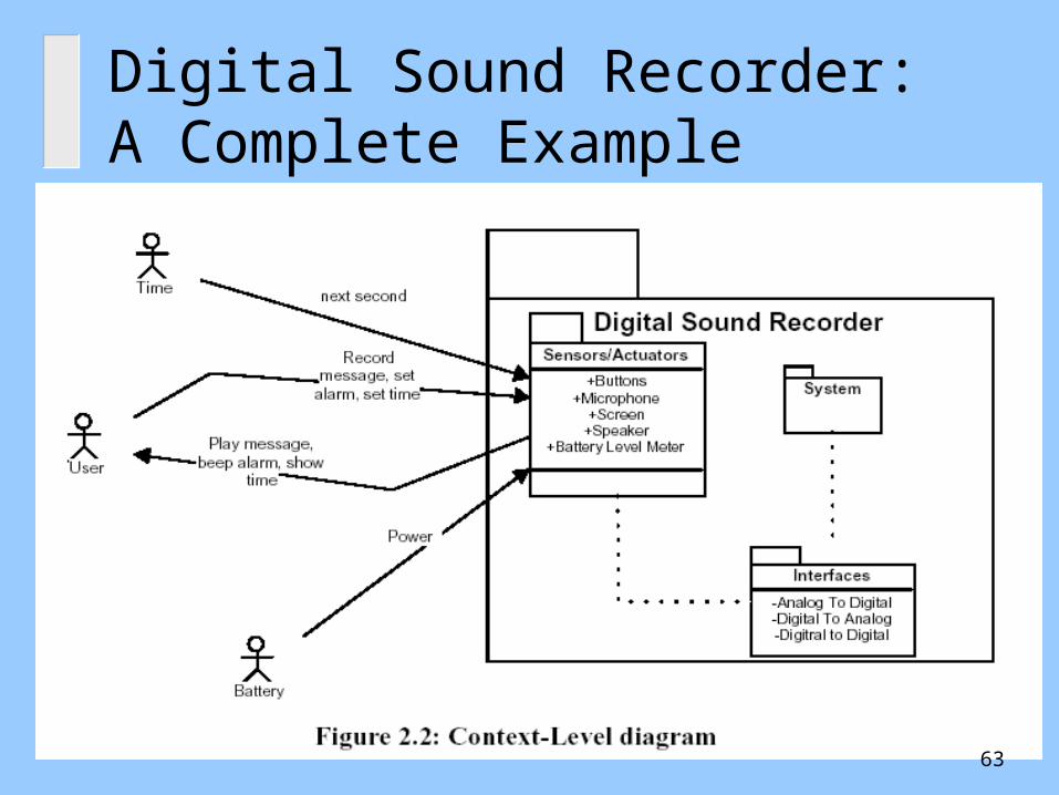
Digital Sound Recorder:A Complete Example
63

Digital Sound Recorder:A Complete Example
SystemSequenceDiagram
64
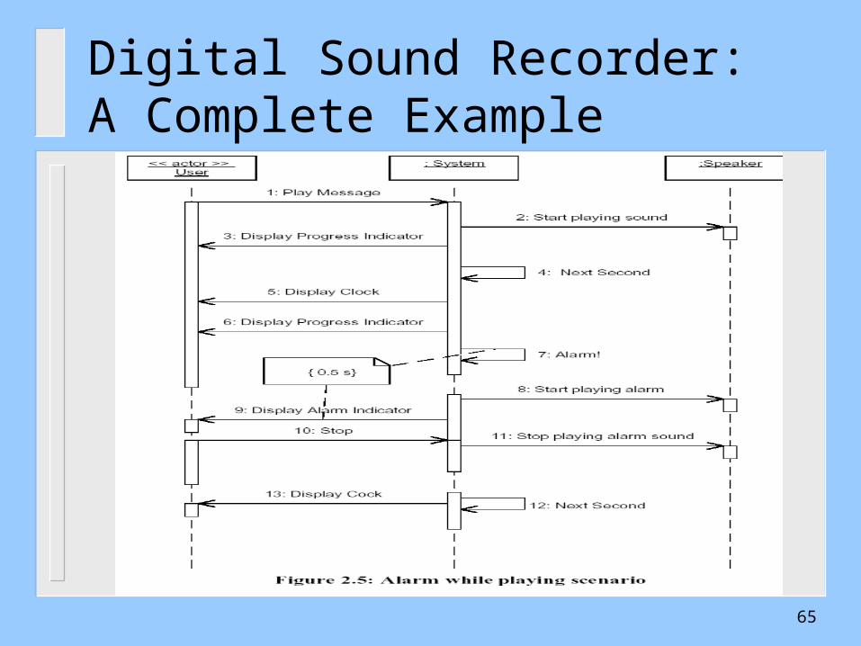
Digital Sound Recorder:A Complete Example
65
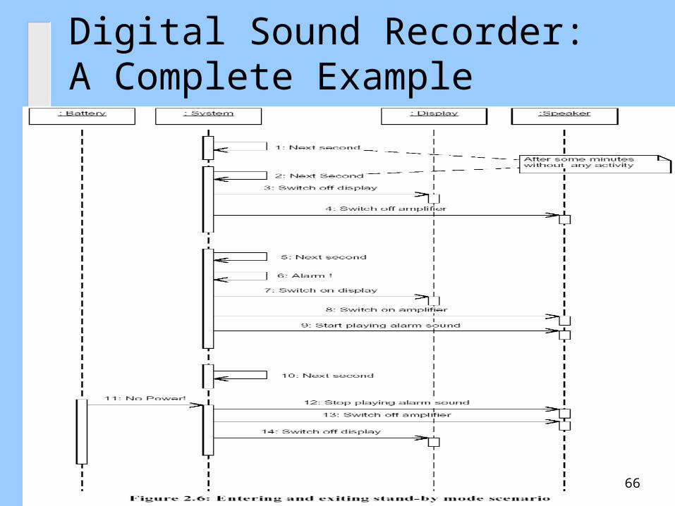
Digital Sound Recorder:A Complete Example
66

Digital Sound Recorder:A Complete Example
AnalysisClass Diagram
67
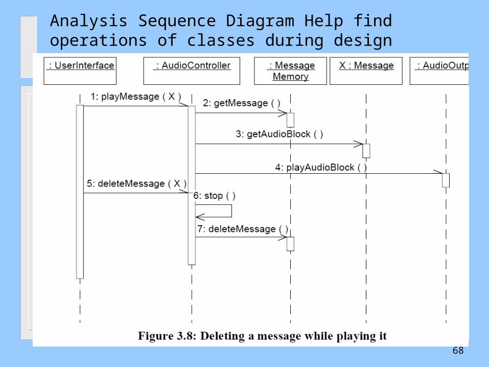
Analysis Sequence Diagram Help find operations of classes during design
68
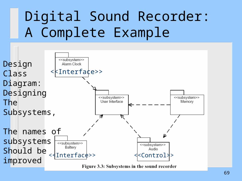
Digital Sound Recorder:A Complete Example
DesignClass Diagram:DesigningThe Subsystems,
The names ofsubsystemsShould beimproved
<<Interface>>
<<Interface>> <<Control>>
69
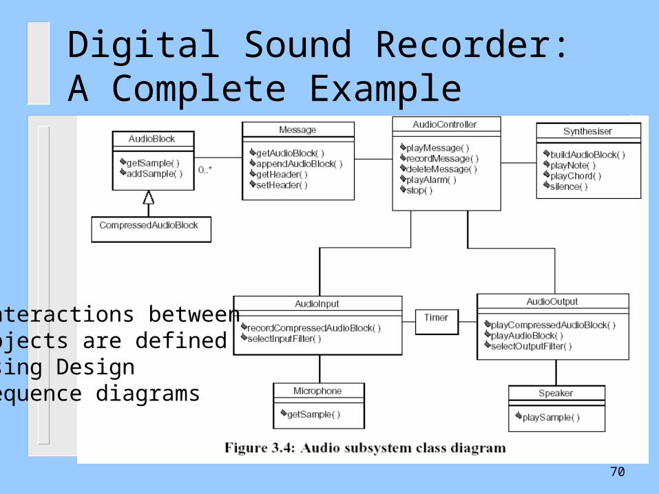
Digital Sound Recorder:A Complete Example
Interactions betweenObjects are defined Using Design Sequence diagrams
70

Digital Sound Recorder:A Complete Example
71

Digital Sound Recorder:A Complete Example
72

Digital Sound Recorder:A Complete Example
73
Outline UML Development – Overview The Requirements, Analysis, and Design Models What is Software Architecture?
– Software Architecture Elements Examples The Process of Designing Software Architectures
– Defining Subsystems– Defining Subsystem Interfaces
Design Using Architectural Styles– Software Architecture Styles– The Attribute Driven Design (ADD)
74
75
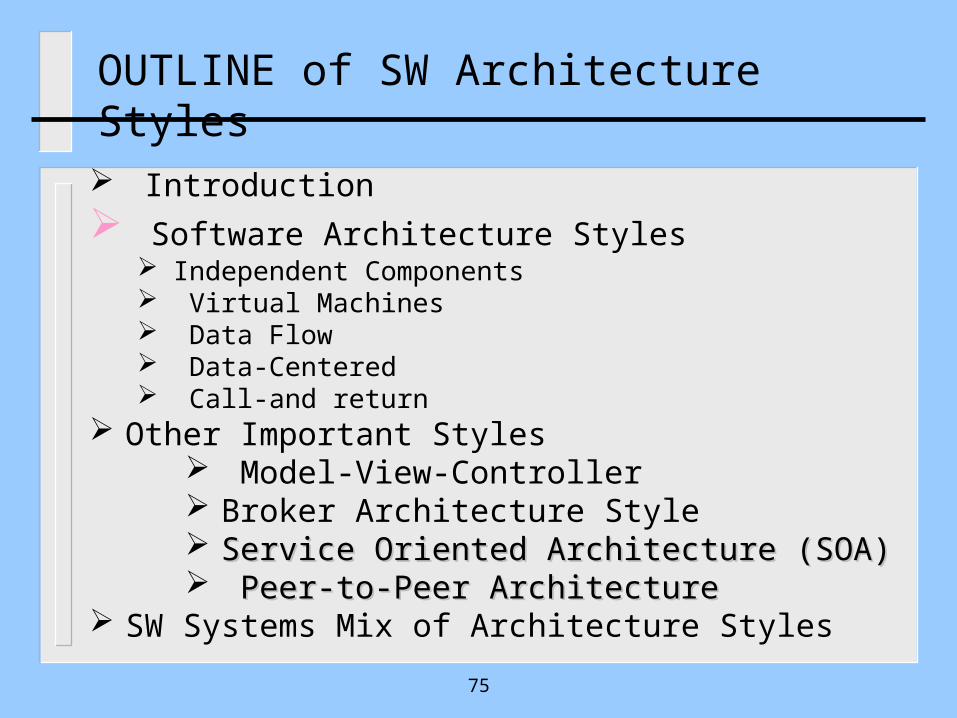
OUTLINE of SW Architecture Styles
Introduction Software Architecture Styles
Independent Components Virtual Machines Data Flow Data-Centered Call-and return
Other Important Styles Model-View-Controller Broker Architecture Style Service Oriented Architecture (SOA)Service Oriented Architecture (SOA) Peer-to-Peer ArchitecturePeer-to-Peer Architecture
SW Systems Mix of Architecture Styles
Design Using Architectural Styles
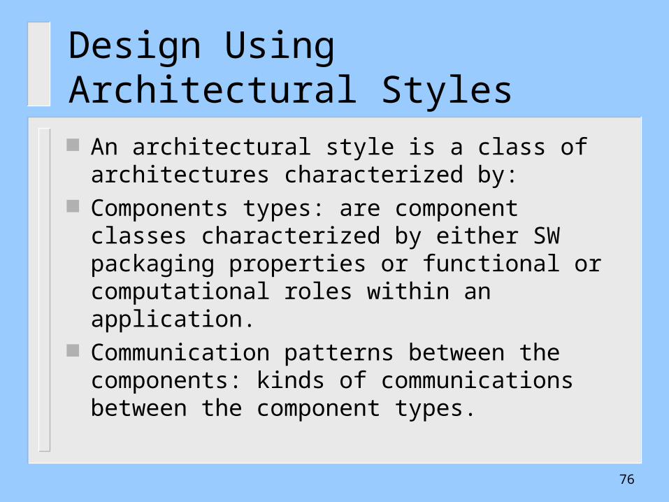
An architectural style is a class of architectures characterized by:
Components types: are component classes characterized by either SW packaging properties or functional or computational roles within an application.
Communication patterns between the components: kinds of communications between the component types.
76

77
Families of Architecture Styles
There is a number of families of styles that has been defined and used in many software systems Notable examples are:
1. Independent Components: Event-based Architectures
2. Virtual Machines
3. Data Flow: Pipes and Filters
4. Data-Centered Systems
5. Call-and Return Architectures
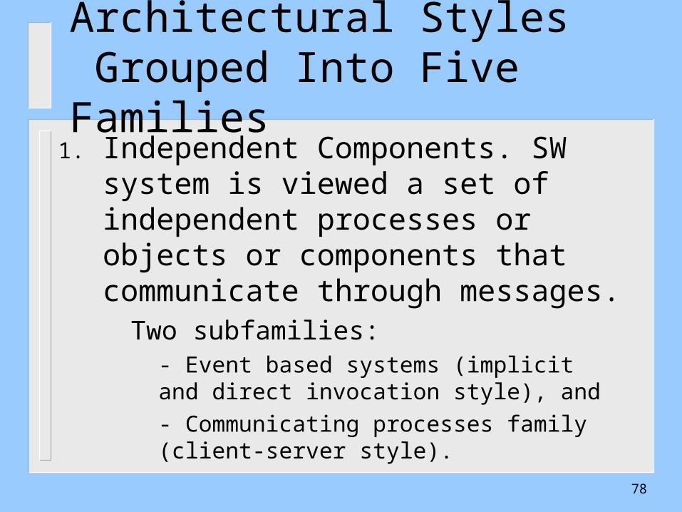
Architectural Styles Grouped Into Five Families
1. Independent Components. SW system is viewed a set of independent processes or objects or components that communicate through messages.
Two subfamilies: - Event based systems (implicit and direct invocation style), and
- Communicating processes family (client-server style).
78
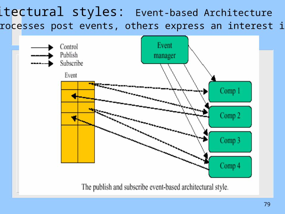
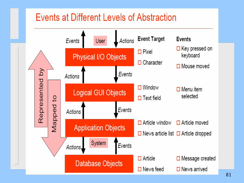
Architectural styles: Event-based ArchitectureSome processes post events, others express an interest in events
79
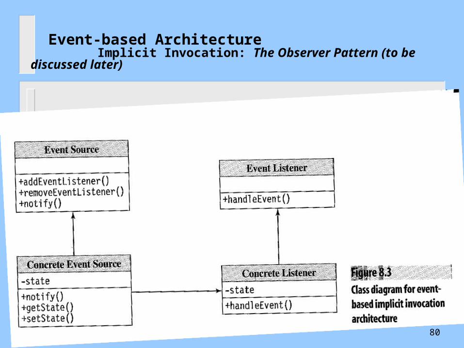
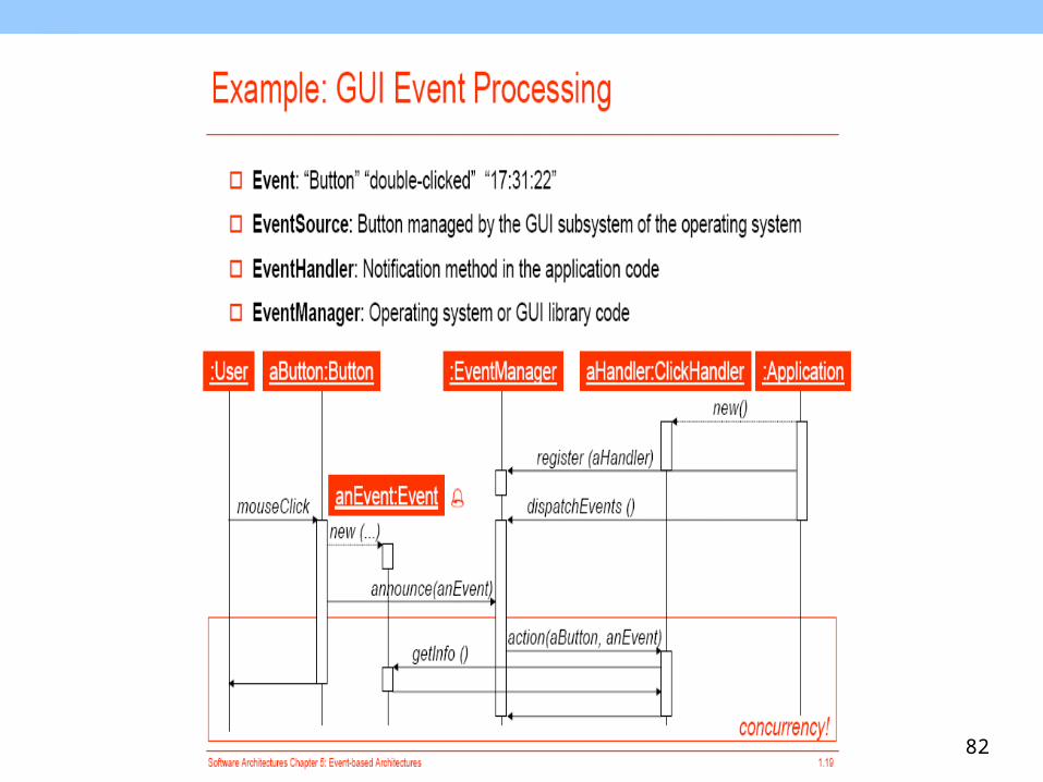
Event-based Architecture Implicit Invocation: The Observer Pattern (to be discussed later)
80
81
82
83
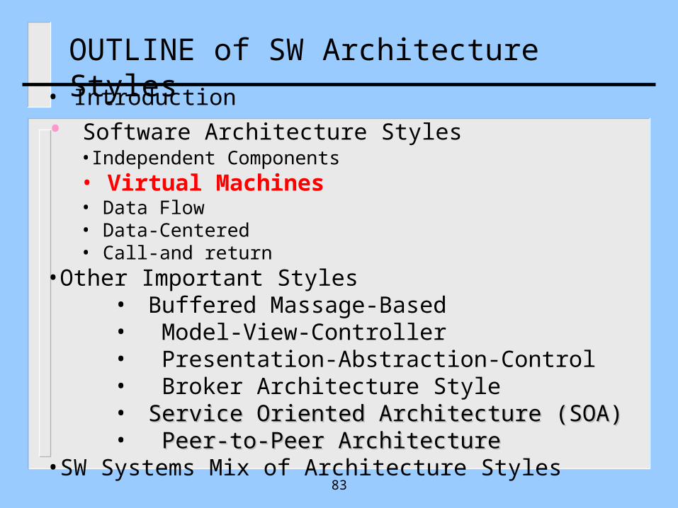
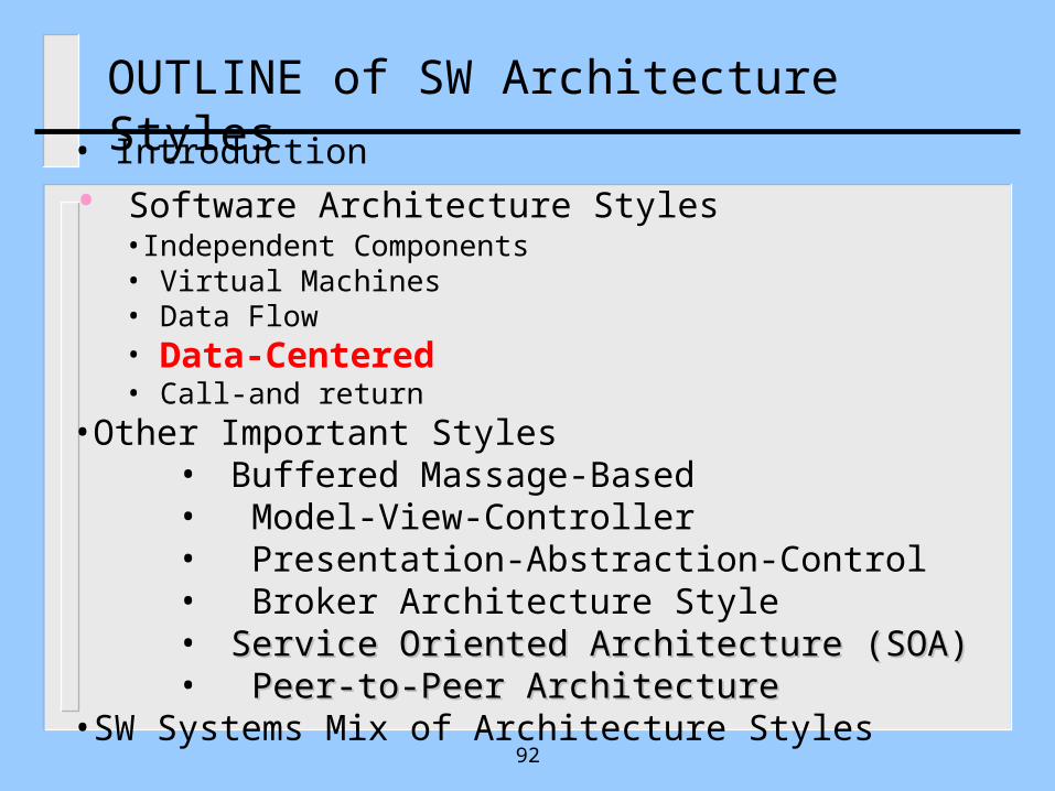
OUTLINE of SW Architecture Styles• Introduction
• Software Architecture Styles•Independent Components• Virtual Machines• Data Flow• Data-Centered• Call-and return
•Other Important Styles• Buffered Massage-Based • Model-View-Controller• Presentation-Abstraction-Control• Broker Architecture Style• Service Oriented Architecture (SOA)Service Oriented Architecture (SOA)• Peer-to-Peer ArchitecturePeer-to-Peer Architecture
•SW Systems Mix of Architecture Styles
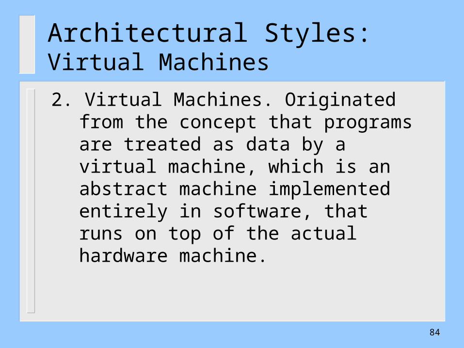
Architectural Styles: Virtual Machines
2. Virtual Machines. Originated from the concept that programs are treated as data by a virtual machine, which is an abstract machine implemented entirely in software, that runs on top of the actual hardware machine.
84
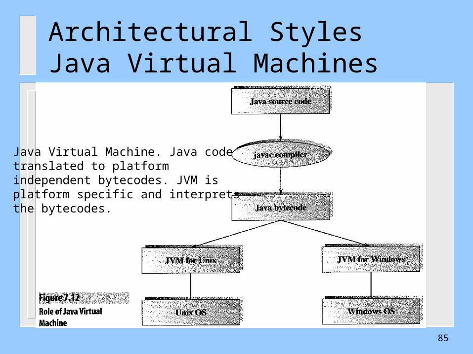
Architectural Styles Java Virtual Machines
Java Virtual Machine. Java code translated to platform independent bytecodes. JVM is platform specific and interprets the bytecodes.
85
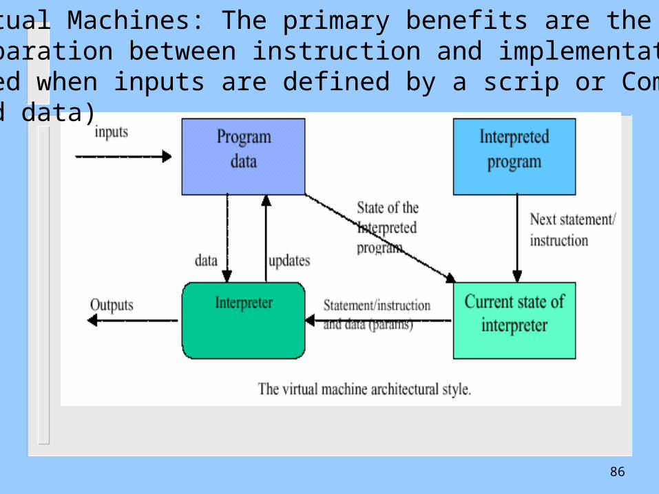
Virtual Machines: The primary benefits are the separation between instruction and implementation,(Used when inputs are defined by a scrip or Commands, and data)
86

87
OUTLINE of SW Architecture Styles• Introduction
• Software Architecture Styles•Independent Components• Virtual Machines• Data Flow• Data-Centered• Call-and return
•Other Important Styles• Buffered Massage-Based • Model-View-Controller• Presentation-Abstraction-Control• Broker Architecture Style• Service Oriented Architecture (SOA)Service Oriented Architecture (SOA)• Peer-to-Peer ArchitecturePeer-to-Peer Architecture
•SW Systems Mix of Architecture Styles
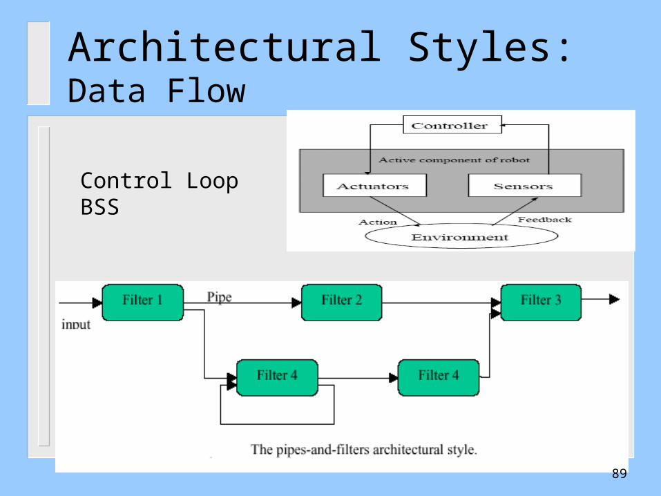
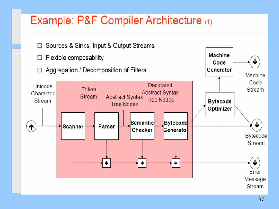
3. Data Flow. Include batch sequential systems (BSS) and pipes and filters (PF).
– - BSS: different components take turns at processing a batch of data, each saving the result of their processing in a shared repository that the next component can access. Ex. Dynamic control of physical processes based on a feedback loop.
- PF: A stream of data processed by a complex structure of processes (filters). Ex, UNIX.
Architectural Styles: Data Flow
88
Architectural Styles: Data Flow
Control LoopBSS
89
90
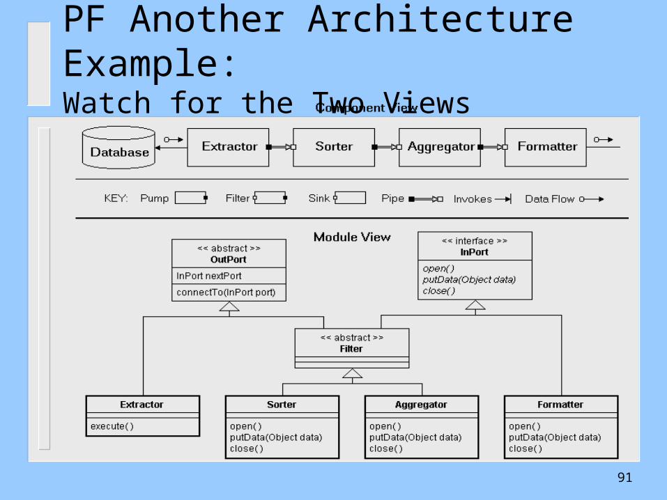
PF Another Architecture Example:Watch for the Two Views
91
92
OUTLINE of SW Architecture Styles• Introduction
• Software Architecture Styles•Independent Components• Virtual Machines• Data Flow• Data-Centered• Call-and return
•Other Important Styles• Buffered Massage-Based • Model-View-Controller• Presentation-Abstraction-Control• Broker Architecture Style• Service Oriented Architecture (SOA)Service Oriented Architecture (SOA)• Peer-to-Peer ArchitecturePeer-to-Peer Architecture
•SW Systems Mix of Architecture Styles
Architectural Styles
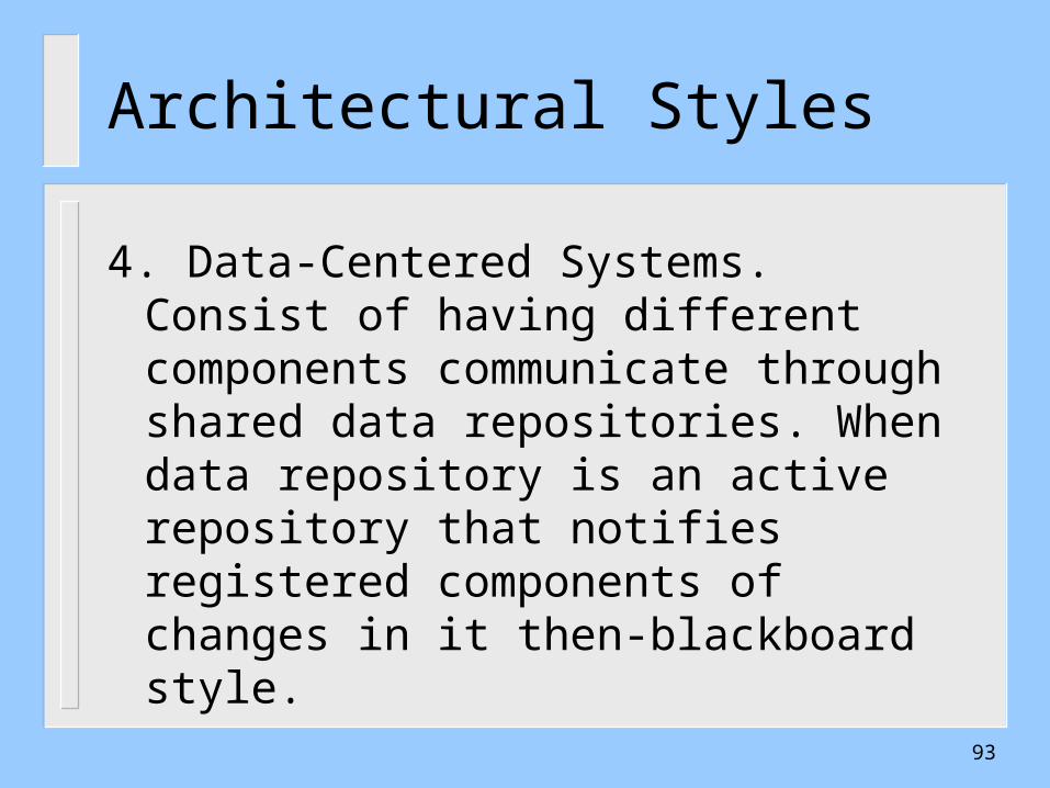
4. Data-Centered Systems. Consist of having different components communicate through shared data repositories. When data repository is an active repository that notifies registered components of changes in it then-blackboard style.
93
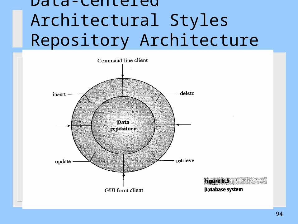
Data-Centered Architectural StylesRepository Architecture Style
94
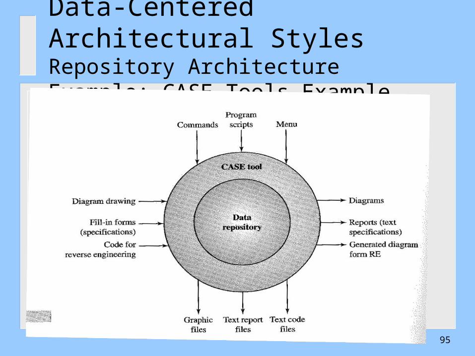
Data-Centered Architectural StylesRepository Architecture Example: CASE Tools Example
95

Data-Centered Architectural StylesRepository Architecture Example: Compiler Architecture
96

Data-Centered Systems: Central data repository Components perusing shared data, and communicating through it.Used in Database intensive systems
97

Data-Centered Architectural StylesBlackboard Architecture Style Example
Compare with the PFs Style
98
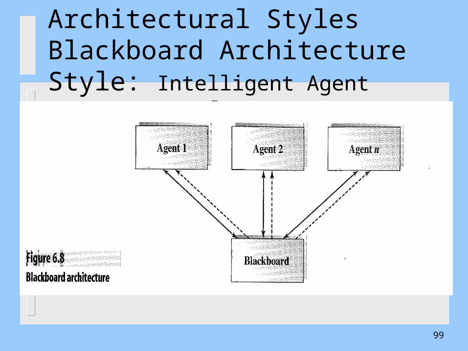
Data-Centered Architectural StylesBlackboard Architecture Style: Intelligent Agent Systems Example
99

Data-Centered Architectural StylesBlackboard Architecture Style: Travel Counseling System Example
100
101
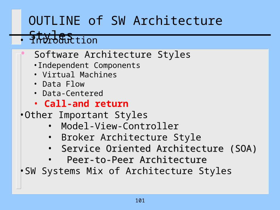
OUTLINE of SW Architecture Styles• Introduction
• Software Architecture Styles•Independent Components• Virtual Machines• Data Flow• Data-Centered• Call-and return
•Other Important Styles• Model-View-Controller• Broker Architecture Style• Service Oriented Architecture (SOA)Service Oriented Architecture (SOA)• Peer-to-Peer ArchitecturePeer-to-Peer Architecture
•SW Systems Mix of Architecture Styles
Architectural styles
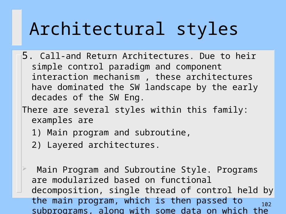
5. Call-and Return Architectures. Due to heir simple control paradigm and component interaction mechanism , these architectures have dominated the SW landscape by the early decades of the SW Eng.
There are several styles within this family: examples are
1) Main program and subroutine,
2) Layered architectures.
Main Program and Subroutine Style. Programs are modularized based on functional decomposition, single thread of control held by the main program, which is then passed to subprograms, along with some data on which the subprograms can operate. 102
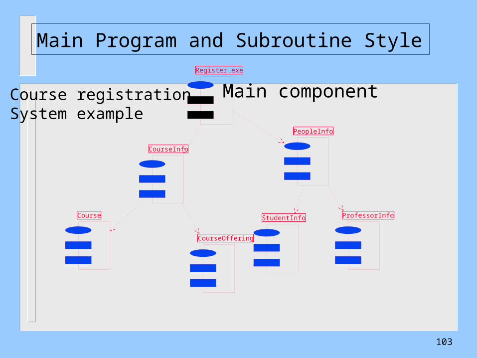
Main Program and Subroutine Style
CourseInfo
PeopleInfo
Course
CourseOffering
StudentInfo ProfessorInfo
Register.exe
Course registrationSystem example
Main component
103

Architectural styles
-) Layered. Functionality is divided into layers of abstraction-each layer provides services to the layer(s) above it, and uses the services of layer(s) below it. In its purest form, each layer access only the layer below it, but does not depend on other lower layers.
104
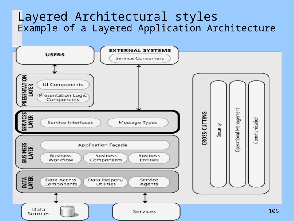
Layered Architectural stylesExample of a Layered Application Architecture
105
106
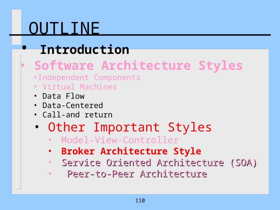
OUTLINE• Introduction• Software Architecture Styles
•Independent Components• Virtual Machines• Data Flow• Data-Centered• Call-and return
• Other Important Styles• Model-View-Controller• Broker Architecture Style• Service Oriented Architecture (SOA)Service Oriented Architecture (SOA)• Peer-to-Peer ArchitecturePeer-to-Peer Architecture
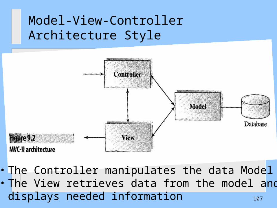
Model-View-Controller Architecture Style
• The Controller manipulates the data Model• The View retrieves data from the model and
displays needed information 107
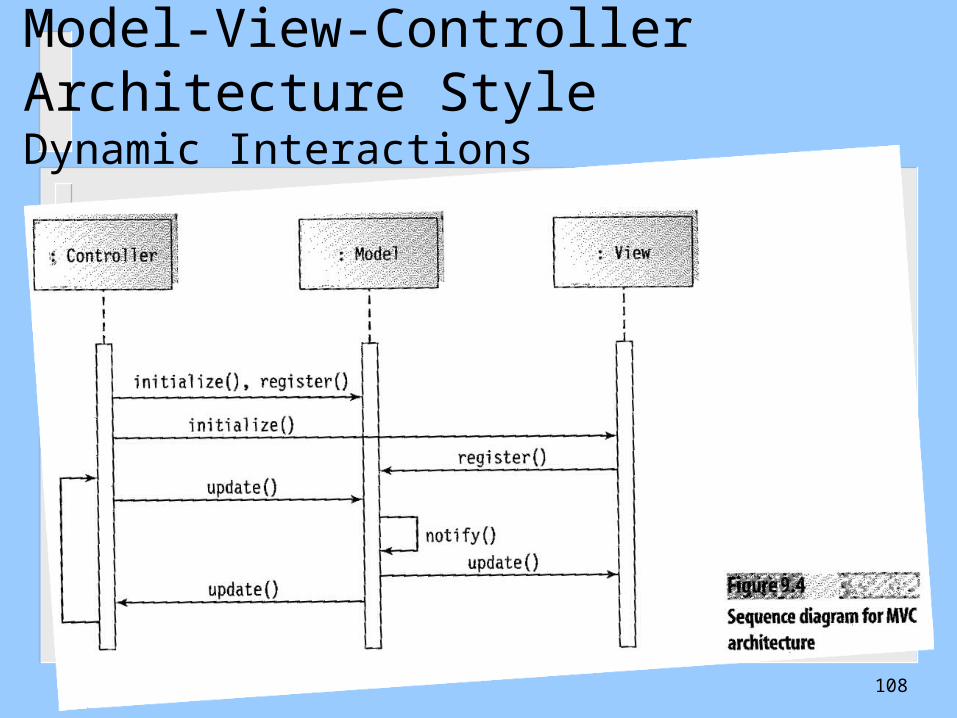
Model-View-Controller Architecture StyleDynamic Interactions
108
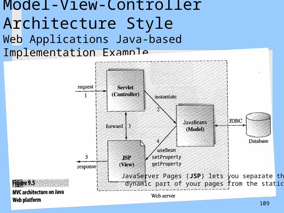
Model-View-Controller Architecture StyleWeb Applications Java-based Implementation Example
JavaServer Pages (JSP) lets you separate the dynamic part of your pages from the static HTML
109
110
OUTLINE• Introduction• Software Architecture Styles
•Independent Components• Virtual Machines• Data Flow• Data-Centered• Call-and return
• Other Important Styles• Model-View-Controller• Broker Architecture Style• Service Oriented Architecture (SOA)Service Oriented Architecture (SOA)• Peer-to-Peer ArchitecturePeer-to-Peer Architecture
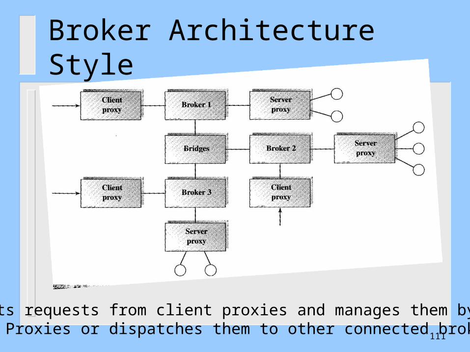
Broker Architecture Style
Brokers gets requests from client proxies and manages them by forwarding to server Proxies or dispatches them to other connected brokers
111

Broker Architecture Style
112
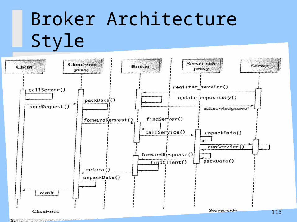
Broker Architecture Style
113
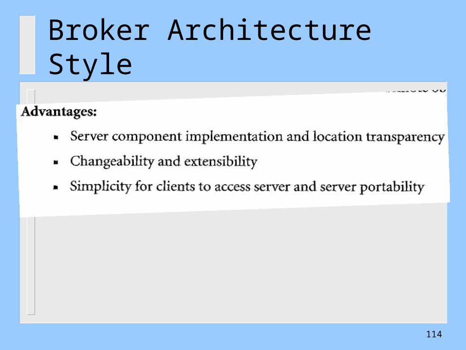
Broker Architecture Style
114
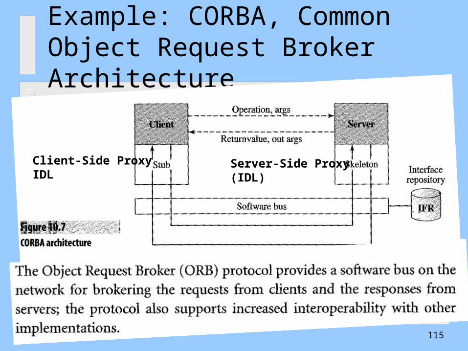
Example: CORBA, Common Object Request Broker Architecture
Client-Side ProxyIDL
Server-Side Proxy(IDL)
115
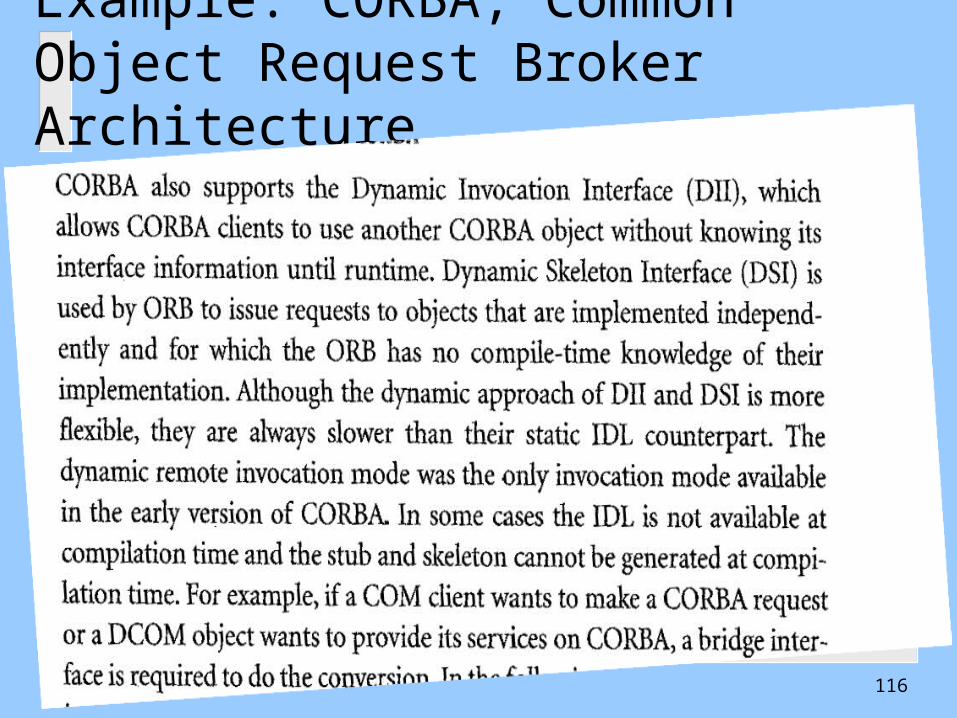
Example: CORBA, Common Object Request Broker Architecture
116

117
OUTLINE• Introduction• Software Architecture Styles
•Independent Components• Virtual Machines• Data Flow• Data-Centered• Call-and return
• Other Important Styles• Model-View-Controller• Broker Architecture Style• Service Oriented Architecture (SOA)Service Oriented Architecture (SOA)• Peer-to-Peer ArchitecturePeer-to-Peer Architecture

Service Oriented Architecture (SOA) Service Oriented Architecture (SOA) StyleStyleMakes use of an Enterprise Service Bus ESBMakes use of an Enterprise Service Bus ESBUsed in web-based systems and distributed computingUsed in web-based systems and distributed computing
nodes make resources available to other nodes make resources available to other participants in the system as independent services thatparticipants in the system as independent services that the participants access in a standardized way using the ESBthe participants access in a standardized way using the ESB
BeforeSOA
The SOA Style
118
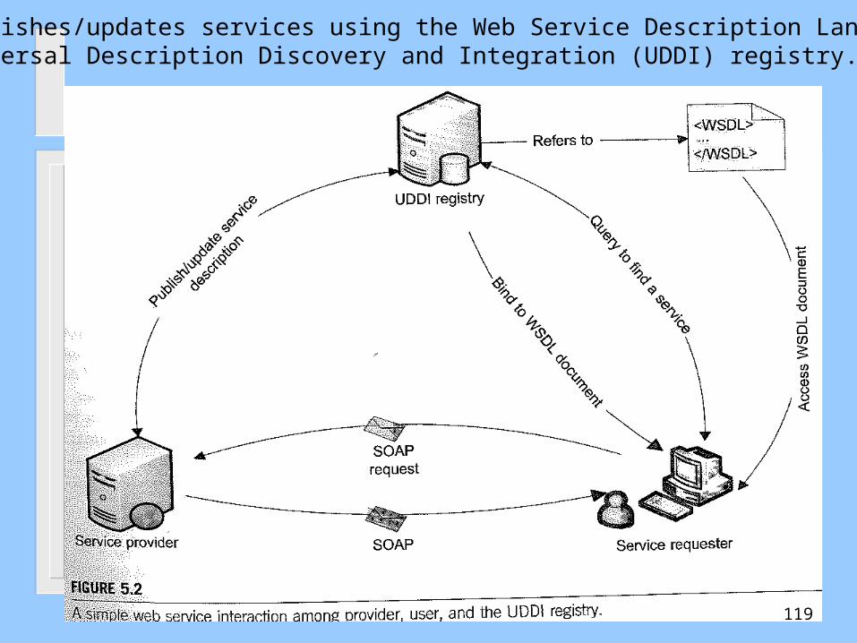
The SP publishes/updates services using the Web Service Description Language (WSDL)On the Universal Description Discovery and Integration (UDDI) registry.
119
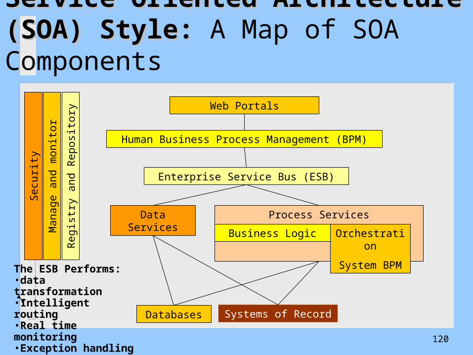
Service Oriented Architecture (SOA) Service Oriented Architecture (SOA) Style: Style: A Map of SOA Components
Process Services
Orchestration
System BPM
Business Logic
Databases
Data Services
Enterprise Service Bus (ESB)
Systems of Record
Web Portals
Human Business Process Management (BPM)
Sec
urity
Reg
istr
y an
d R
epos
itory
Man
age
and
mon
itor
The ESB Performs: •data transformation•Intelligent routing•Real time monitoring•Exception handling•Service security
120

Cloud Services ArchitectureSOA supports Cloud Computing Models
The Grid of Servicesand Resources
Clients request the Grid Servicesand Resources from the Service Directory
121
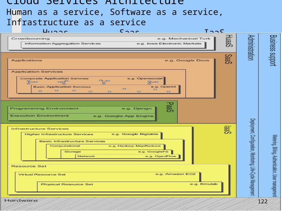
Cloud Services ArchitectureHuman as a service, Software as a service, Infrastructure as a service Huaas Saas IaaS
122
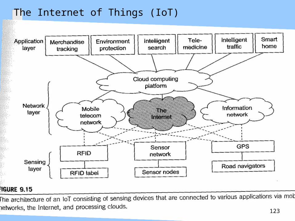
The Internet of Things (IoT)
123

Example in Telemedicine
124

125
126
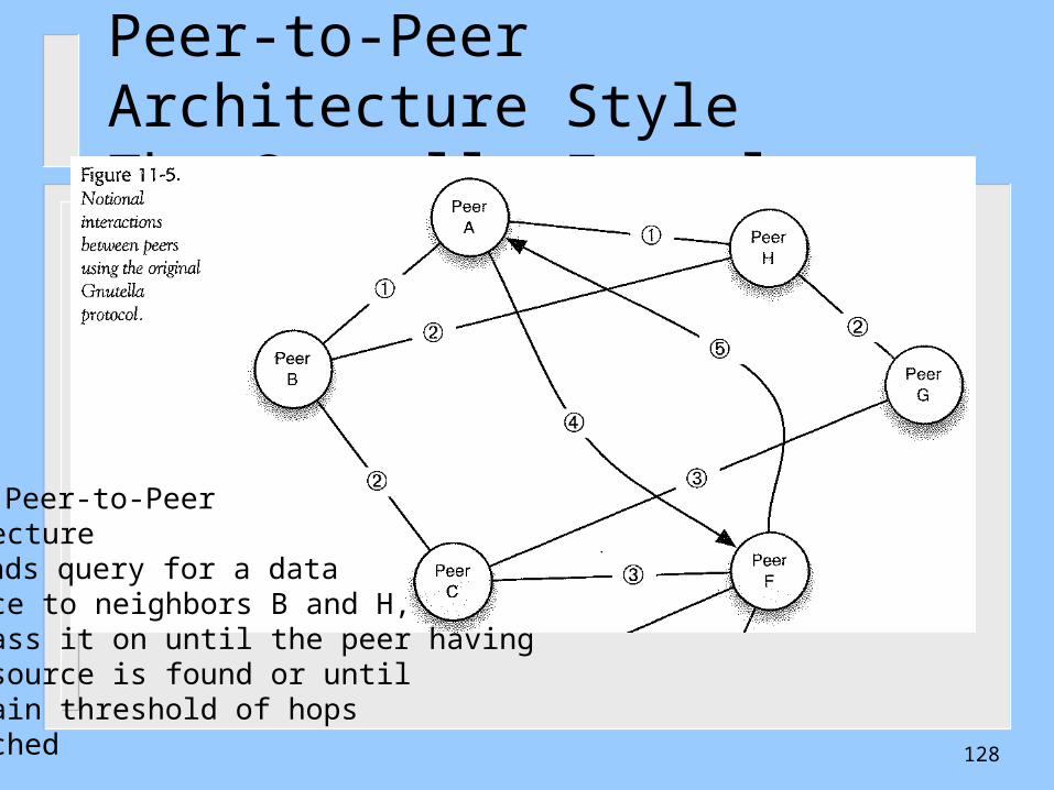
OUTLINE• Introduction• Software Architecture Styles
•Independent Components• Virtual Machines• Data Flow• Data-Centered• Call-and return
• Other Important Styles• Model-View-Controller• Broker Architecture Style• Service Oriented Architecture (SOA)Service Oriented Architecture (SOA)• Peer-to-Peer ArchitecturePeer-to-Peer Architecture
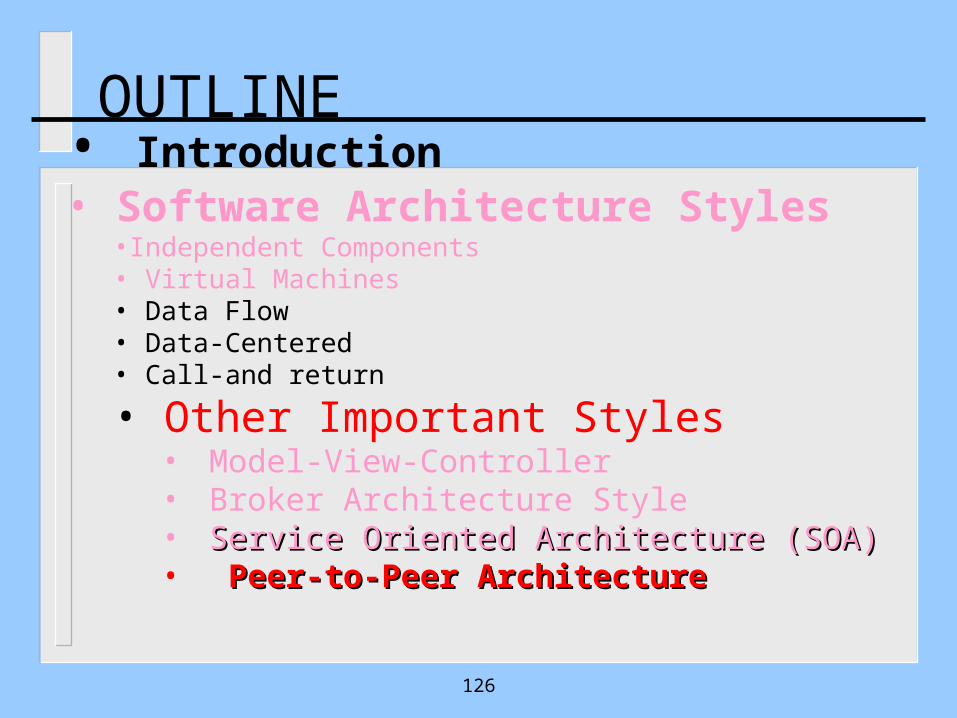
Peer-to-Peer Architecture Style
127
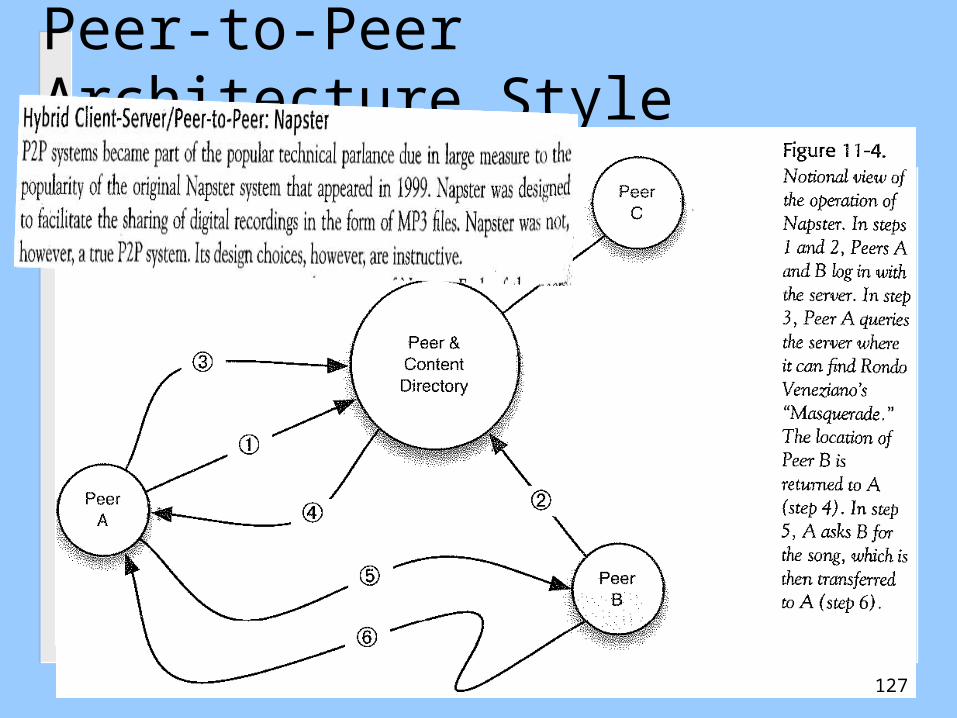
Peer-to-Peer Architecture StyleThe Gnutella Example
• Pure Peer-to-PeerArchitecture• A sends query for a data resource to neighbors B and H, they pass it on until the peer havingthe resource is found or until a certain threshold of hopsis reached 128
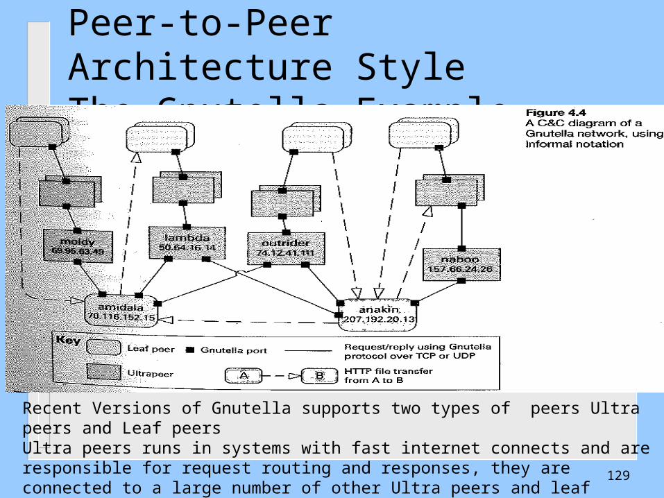
Peer-to-Peer Architecture StyleThe Gnutella Example
Recent Versions of Gnutella supports two types of peers Ultra peers and Leaf peersUltra peers runs in systems with fast internet connects and are responsible for request routing and responses, they are connected to a large number of other Ultra peers and leaf peers, while the leaf peers are connected to a small number of Ultra peers
129

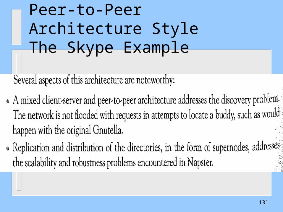
Peer-to-Peer Architecture StyleThe Skype Example
• A mixed client-Server and Pee-to-Peer• Skype Peers get promoted to a supernode status based on their network connectivityAnd machine performance• Supernodes perform the Communication and routingof massages to establish a call• When a user logs in to the serverhe is connected to a supernode• If a peer becomes a supernode he unknowingly bears the cost of routing a potentially large number of calls.
130
Peer-to-Peer Architecture StyleThe Skype Example
131
Conclusions• An architectural style is a coordinated set of
architectural constraints that restricts the roles/features of architectural elements and the allowed relationships among those elements
• Choosing a style to implement a particular system depends on several factors based on stakeholders concerns and quality attributes
• Most SW systems use a mix of architecture styles
132
SW Systems-Mix of Architecture Styles
Most SW systems use a mix of architecture styles. Ex, personnel management system with a scheduling component, implemented using the independent component style, and a payroll component, using the batch sequential style.
Choosing a style to implement a particular system depends on several factors. The technical factors concern the level of quality attributes that each style enables us to attain. EX, event-based systems-achieve very high level of evolvability, at the expense of performance and complexity. Virtual-machine style-achieve very high level of portability, at expense of performance and perhaps even testability.
133
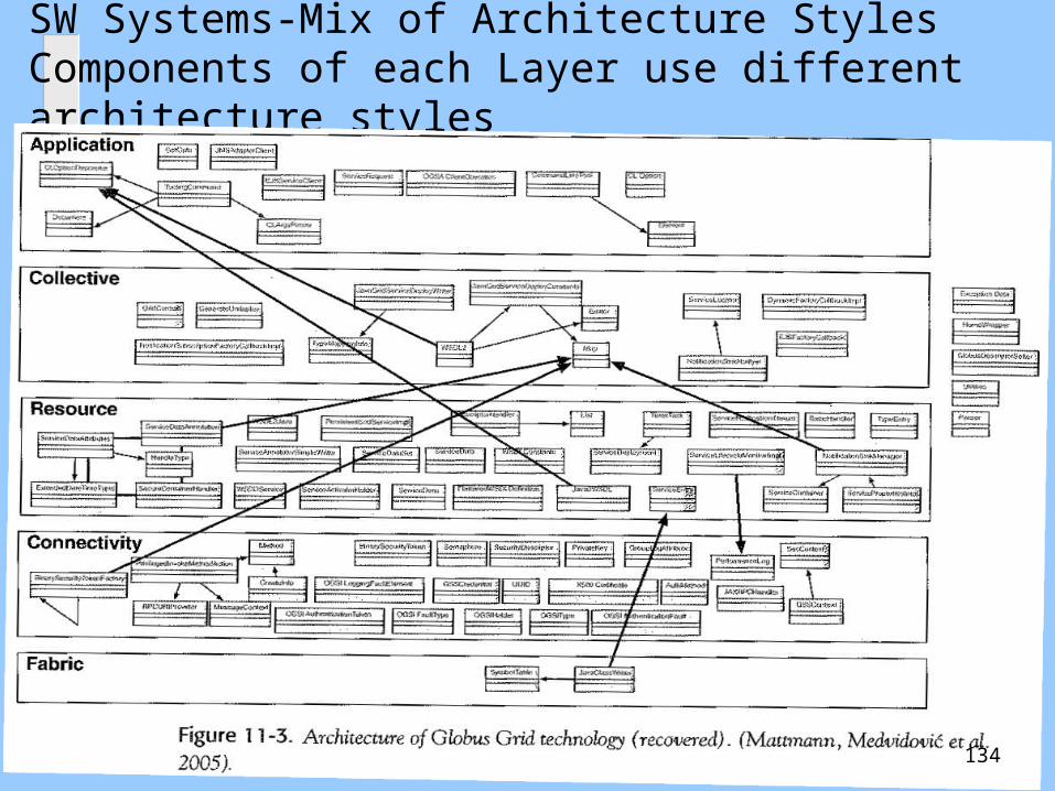
SW Systems-Mix of Architecture StylesComponents of each Layer use different architecture styles
134

SW Systems-Mix of Architecture Styles
135
Outline
UML Development – Overview The Requirements, Analysis, and Design Models What is Software Architecture?
– Software Architecture Elements Examples The Process of Designing Software Architectures
– Defining Subsystems– Defining Subsystem Interfaces
Design Using Architectural Styles– Software Architecture Styles– The Attribute Driven Design (ADD)
136
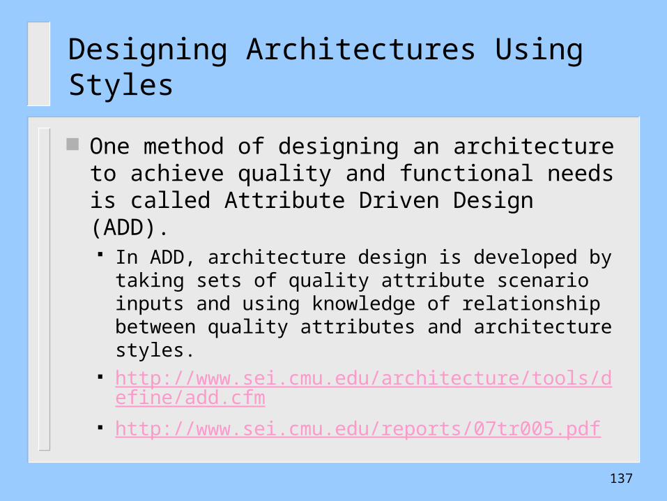
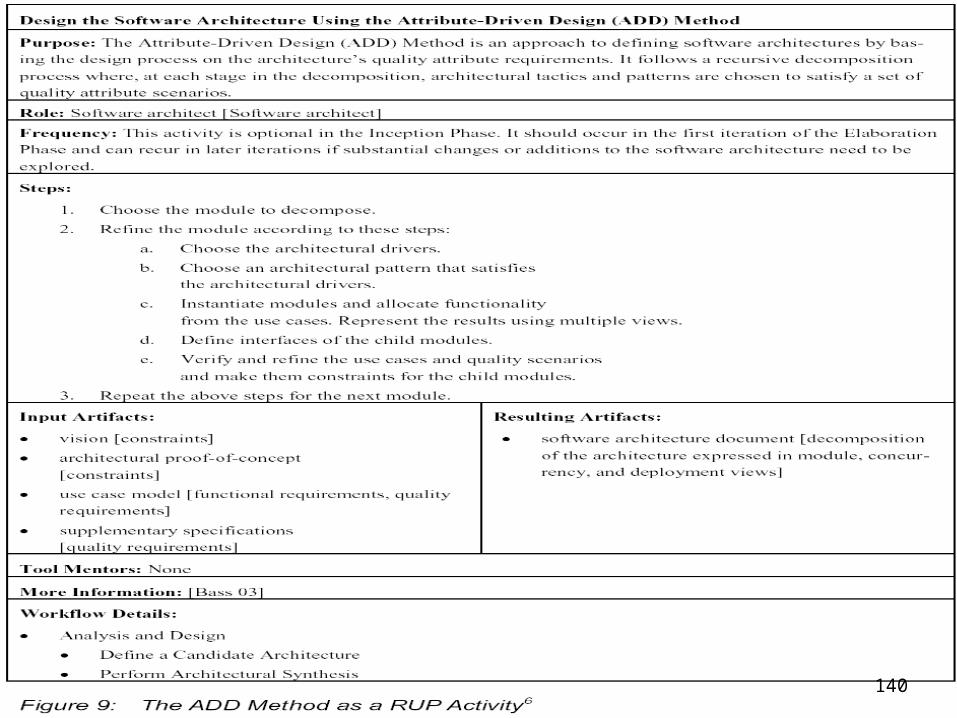
Designing Architectures Using Styles
One method of designing an architecture to achieve quality and functional needs is called Attribute Driven Design (ADD). In ADD, architecture design is developed by taking sets
of quality attribute scenario inputs and using knowledge of relationship between quality attributes and architecture styles.
http://www.sei.cmu.edu/architecture/tools/define/add.cfm
http://www.sei.cmu.edu/reports/07tr005.pdf
137
Attribute-Driven Design (ADD)
A Method for producing software architecture based on process decomposition, stepwise refinement and fulfillment of attribute qualities.
It is a recursive process where at each repetition, tactics and an architecture style or a pattern is chosen to fulfill quality attribute needs.
138
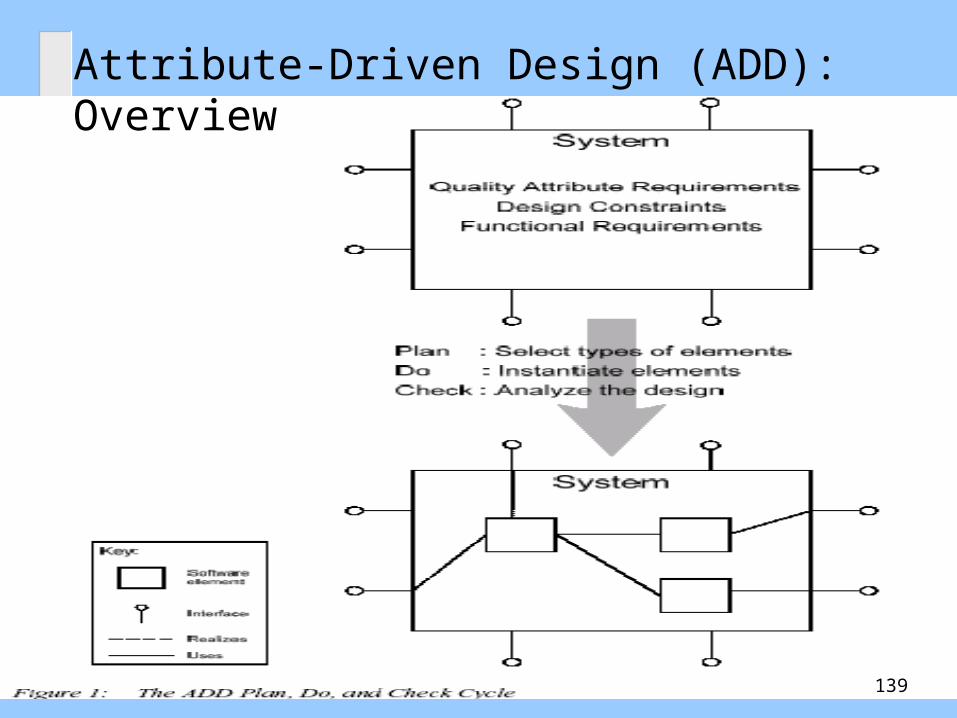
Attribute-Driven Design (ADD): Overview
139
140

Updated ADD Stepshttp://www.dtic.mil/cgi-bin/GetTRDoc?Location=U2&doc=GetTRDoc.pdf&AD=ADA460414
141

Step 1: Confirm There Is Sufficient Requirements Information
WHAT DOES STEP 1 INVOLVE?1. Make sure that the system’s stakeholders have prioritized the requirements according to business and mission goals.2. You should also confirm that there is sufficient information about the quality attribute requirements to proceed.
142

Step 2: Choose an Element of the System to Decompose
In this second step, you choose which element of the system will be the design focus in subsequent steps. You can arrive at this step in one of two ways:1. You reach Step 2 for the first time. The only element you
can decompose is the system itself. By default, all requirements are assigned to that system.
2. You are refining a partially designed system and have visited Step 2 before.4 In this case, the system has been partitioned into two or more elements, and requirements have been assigned to those elements. You must choose one of these elements as the focus of subsequent steps.
143
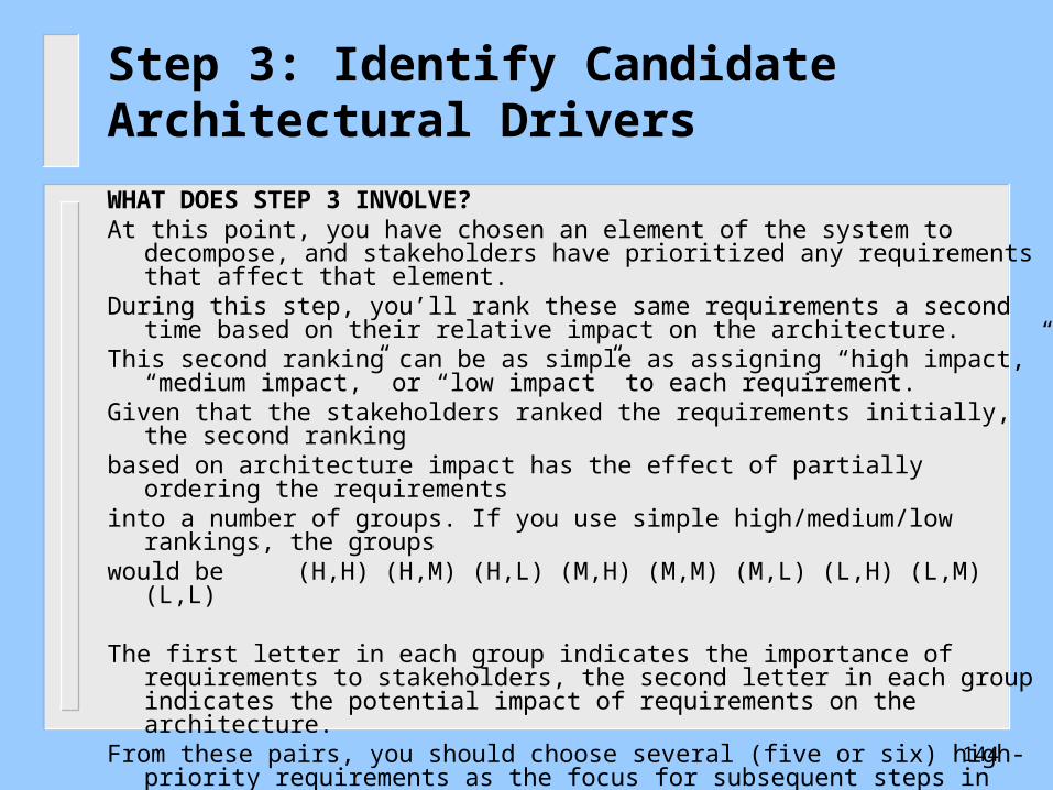
Step 3: Identify Candidate Architectural Drivers
WHAT DOES STEP 3 INVOLVE?At this point, you have chosen an element of the system to decompose, and stakeholders
have prioritized any requirements that affect that element. During this step, you’ll rank these same requirements a second time based on their
relative impact on the architecture. This second ranking can be as simple as assigning “high impact,” “medium impact,” or
“low impact” to each requirement.Given that the stakeholders ranked the requirements initially, the second rankingbased on architecture impact has the effect of partially ordering the requirementsinto a number of groups. If you use simple high/medium/low rankings, the groupswould be (H,H) (H,M) (H,L) (M,H) (M,M) (M,L) (L,H) (L,M) (L,L)
The first letter in each group indicates the importance of requirements to stakeholders, the second letter in each group indicates the potential impact of requirements on the architecture.
From these pairs, you should choose several (five or six) high-priority requirements as the focus for subsequent steps in the design process.
144
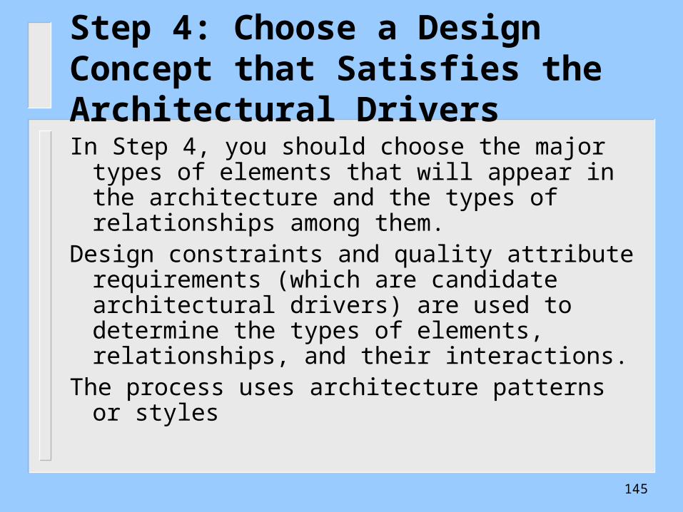
Step 4: Choose a Design Concept that Satisfies the Architectural Drivers
In Step 4, you should choose the major types of elements that will appear in the architecture and the types of relationships among them.
Design constraints and quality attribute requirements (which are candidate architectural drivers) are used to determine the types of elements, relationships, and their interactions.
The process uses architecture patterns or styles
145
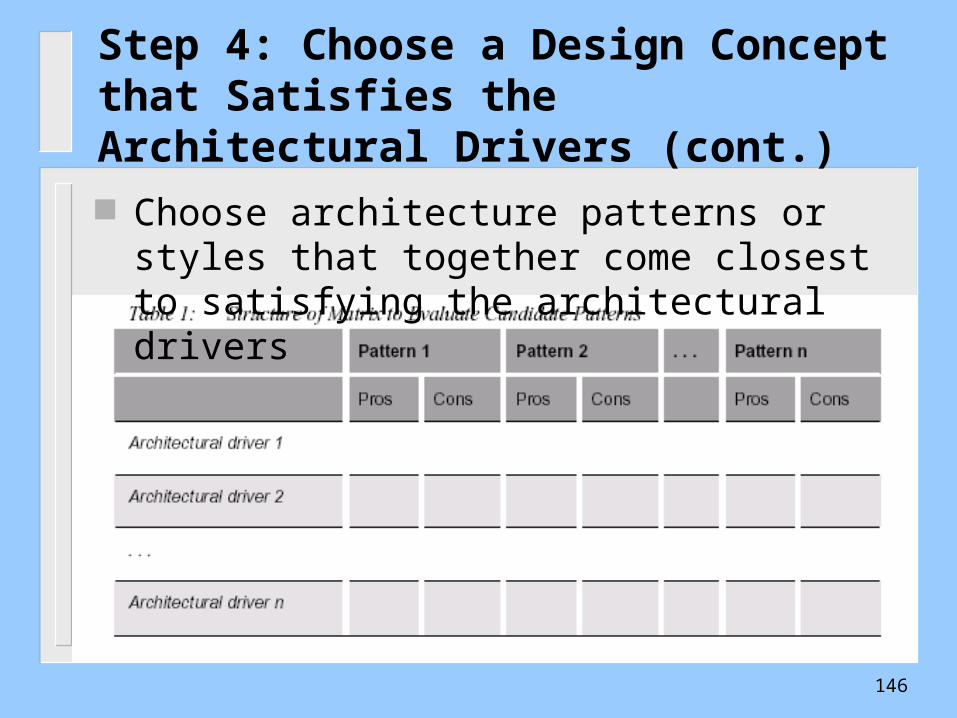
Step 4: Choose a Design Concept that Satisfies the Architectural Drivers (cont.)
Choose architecture patterns or styles that together come closest to satisfying the architectural drivers
146
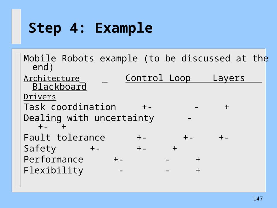
Step 4: Example
Mobile Robots example (to be discussed at the end) Architecture Control Loop Layers
BlackboardDriversTask coordination +- - +Dealing with uncertainty - +- +Fault tolerance +- +- +-Safety +- +- +Performance +- - +Flexibility - - +
147

Step 4: Major Design Decisions
Decide on an overall design concept that includes the major types of elements that will appear in the architecture and the types of relationships among them.
Identify some of the functionality associated with the different types of elements
Decide on the nature and type of communications (synchronous/asynchronous) among the various types of elements (both internal software elements and external entities)
148
Step 5: Instantiate Architectural Elements and Allocate Responsibilities In Step 5, you instantiate the various types of software
elements you chose in the previous step. Instantiated elements are assigned responsibilities from the functional requirements (captured in use-cases) according to their types
At the end of Step 5, every functional requirement (in every use-case) associated with the parent element must be represented by a sequence of responsibilities within the child elements.
This exercise might reveal new responsibilities (e.g., resource management). In addition, you might discover new element types and wish to create new instances of them.
149
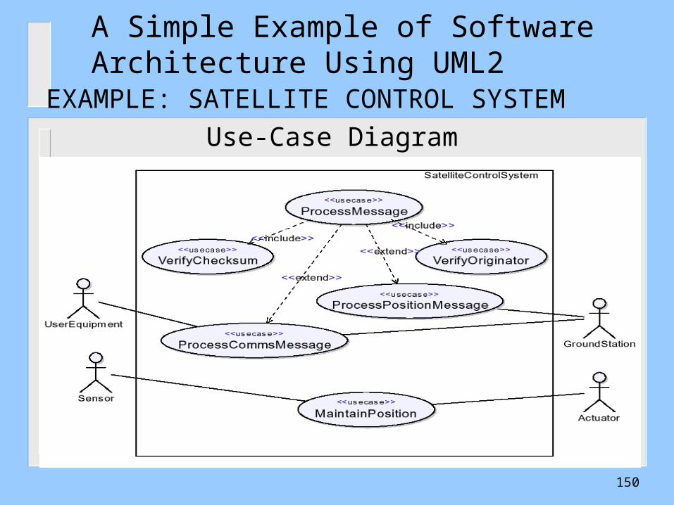
A Simple Example of Software Architecture Using UML2
EXAMPLE: SATELLITE CONTROL SYSTEM
Use-Case Diagram
150
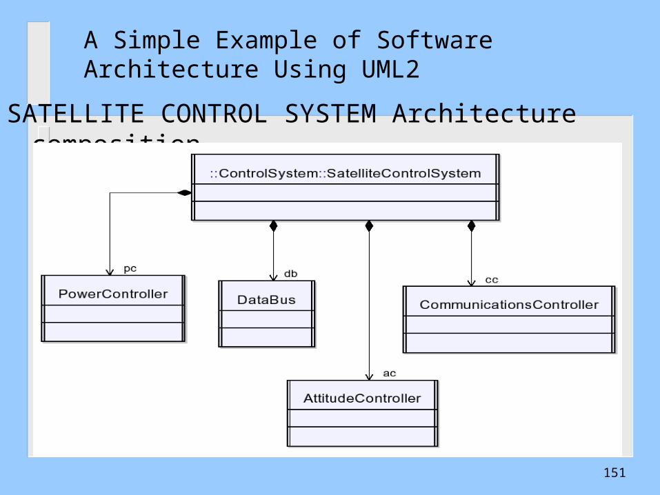
A Simple Example of Software Architecture Using UML2
SATELLITE CONTROL SYSTEM Architecture composition
151
Step 6: Define Interfaces for InstantiatedElements
WHAT DOES STEP 6 INVOLVE? In step 6, you define the services and
properties required and provided by the software elements in our design. In ADD, these services and properties are referred to as the element’s interface.
Interfaces describe the PROVIDES and REQUIRES assumptions that software elements make about one another.
152

SATELLITE CONTROL SYSTEM Architecture Structure
A Simple Example of Software Architecture Using UML2
153
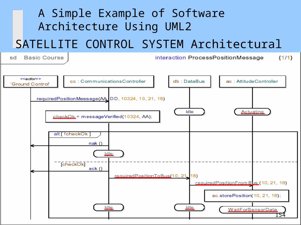
A Simple Example of Software Architecture Using UML2
SATELLITE CONTROL SYSTEM Architectural Behavior
154

Step 6: Major Design Decisions
Decisions will likely involve several of the following:
The external interfaces to the system The interfaces between high-level system
partitions, or subsystems The interfaces between applications within high-
level system partitions The interfaces to the infrastructure (reusable
components or elements, middleware, run-time environment, etc.)
155
Step 7: Verify and Refine Requirements and Make Them Constraints for Instantiated Elements
WHAT DOES STEP 7 INVOLVE? In Step 7, you verify that the element
decomposition thus far meets functional requirements, quality attribute requirements, and design constraints. You also prepare child elements for further decomposition.
Refine quality attribute requirements for individual child elements as necessary (e.g., child elements that must have fault-tolerance, high performance, high security, etc.)
156
Example 1 Mobile Robotics System
Overview– controls manned, partially-manned, orunmanned vehicle--car, submarine, spacevehicle, etc.– System performs tasks that involve planningand dealing with obstacles and other externalfactors.– System has sensors and actuators and real-time
performance constraints.
157
Mobile Robotics System Requirements( Candidate Architecture Drivers)
Req 1: System must provide both
deliberative and reactive behavior.
Req 2: System must deal with uncertainty.
Req. 3 System must deal with dangers in
robot’s operation and environment.
Req. 4: System must be flexible with respect
to experimentation and reconfiguration of
robot and modification of tasks.
158

Choose an architecture style
159

Control Loop ArchitectureEvaluate Control Loop Architecture--Strengths and
Weaknesses w.r.t candidate architecture drivers• Req 1--deliberative and reactive behavior
– advantage-simplicity– drawback-dealing with unpredictability
• feedback loops assumes continuous changes inenvironment and continuous reaction
• robots are often confronted with disparate, discreteevents that require very different modes of reactivebehavior.
– drawback-architecture provides no leverage fordecomposing complex tasks into cooperating components.
160
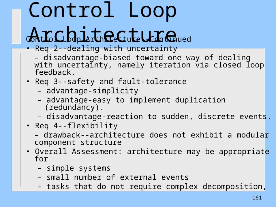
Control Loop ArchitectureControl Loop Architecture--Continued• Req 2--dealing with uncertainty
– disadvantage-biased toward one way of dealing with uncertainty, namely iteration via closed loop feedback.
• Req 3--safety and fault-tolerance– advantage-simplicity– advantage-easy to implement duplication (redundancy).– disadvantage-reaction to sudden, discrete events.
• Req 4--flexibility– drawback--architecture does not exhibit a modular component structure
• Overall Assessment: architecture may be appropriate for– simple systems– small number of external events– tasks that do not require complex decomposition,
161
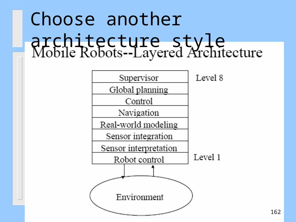
Choose another architecture style
162
Layered Architecture
Evaluate Layered Architecture--Strengths andWeaknesses• Req 1--deliberative and reactive behavior
– advantage-architecture defines clear abstractionlevels to guide design
– drawback-architectural structure does notreflect actual data and control-flow patterns
– drawback-data hierarchy and control hierarchyare not separated.
163
Layered Architecture
Layered Architecture--Continued• Req 2--dealing with uncertainty
– advantage-layers of abstraction should providea good basis for resolving uncertainties.
• Req 3--safety and fault-tolerance– advantage-layers of abstraction should also help(security and fault-tolerance elements in each layer)– drawback-emergency behavior may require
short-circuiting of strict layering for faster recovery when failures occur.
164
Layered Architecture
Layered Architecture--Continued• Req 4--flexibility
– drawback-changes to configuration and/orbehavior may involve several or all layers
• Overall Assessment– layered model is useful for understanding and
organizing system functionality– strict layered architecture may break down with
respect to implementation and flexibility.
165
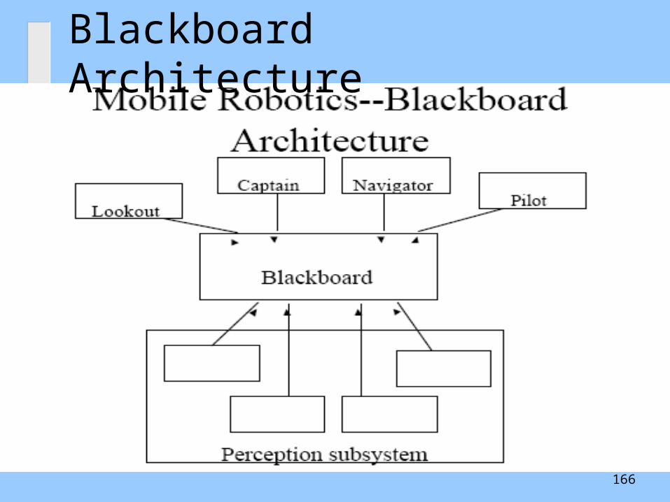
Blackboard Architecture
166
Blackboard Architecture
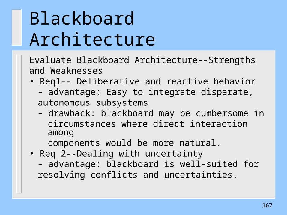
Evaluate Blackboard Architecture--Strengthsand Weaknesses• Req1-- Deliberative and reactive behavior
– advantage: Easy to integrate disparate,autonomous subsystems
– drawback: blackboard may be cumbersome incircumstances where direct interaction amongcomponents would be more natural.
• Req 2--Dealing with uncertainty– advantage: blackboard is well-suited for
resolving conflicts and uncertainties.
167
Blackboard Architecture
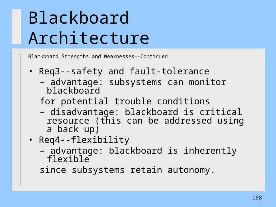
Blackboard Strengths and Weaknesses--Continued
• Req3--safety and fault-tolerance– advantage: subsystems can monitor blackboardfor potential trouble conditions– disadvantage: blackboard is critical resource
(this can be addressed using a back up) • Req4--flexibility
– advantage: blackboard is inherently flexiblesince subsystems retain autonomy.
168
Architecture Comparison
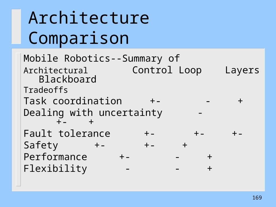
Mobile Robotics--Summary ofArchitectural Control Loop Layers
BlackboardTradeoffsTask coordination +- - +Dealing with uncertainty - +- +Fault tolerance +- +- +-Safety +- +- +Performance +- - +Flexibility - - +
169