
Design of Gravity Outlet Structures
21
to too low a groundwater level, navigation may be hampered, and/or side slopes may become unstable. - Maximum Allowable.Storage Level/MASL: As the water level cannot be kept at DDL constantly (this would lead to economically unfeasible drainage systems), there is a need to define a highest boundary: the MASL. This boundary is equal to the DDL, plus the maximum tolerable rise of the water level in the system. The MASL is determined by the agricultural drainage criteria on which the design of the field drainage system is based (Chapter 17) and by the design criteria which apply to the main drainage system (Chapter 19). The determination of MASL is also based on economic considerations: it is the level at which the investments needed in the drainage system (enlarging storage capacity) outweigh the risk of economic losses (chance of exceeding MASL, multiplied by losses incurred by yield reduction or damage to canals, structures, housing, etc.). Depending on the envisaged land use and on the operation and maintenance requirements of the drainage system, the DDL and the MASL may vary throughout the year. For the design of the outlet structure, the most unfavourable levels should be selected in combination with the highest outer water levels: usually this will be the lowest DDL and MASL and/or the smallest difference between MASL and DDL. 24.3 Design of Gravity Outlet Structures This section reviews the various types of gravity outlet structures, presents the relationships between storage and the hydraulic design of gravity outlets, and formulates guidelines for selecting hydraulic dimensions. 24.3.1 Types of Gravity Outlet Structures Gravity outlet structures can be a drainage sluice with doors, a gated culvert, or a siphon. Drainage Sluice A drainage sluice consists of a weir and a set of doors. Each of the two doors hinges around a vertical axis, and is positioned in such a way that inner water can flow freely to the outer water, whereas they prevent a flow in the opposite direction (Figure 24.18). The doors will remain closed as long as the pressure from the outer water is greater or equal to the pressure from the inner water. In case of fresh water on both sides, an equilibrium situation occurs when the water levels on both sides are equal. When the outer waters are salty, or when they contain a considerably larger sediment load than the inner waters, the densities differ, so that an equilibrium situation will occur when the inner water level is higher and compensates for the (denser) outer water. In case of salt outer water, the inner water level must be around 1 .O12 times the outer water level to have equilibrium (Section 24.3.3). A drainage sluice can be self-operating, manually operated, or automatically operated. 1020
Transcript of Design of Gravity Outlet Structures

to too low a groundwater level, navigation may be hampered, and/or side slopes may become unstable.
- Maximum Allowable.Storage Level/MASL: As the water level cannot be kept at DDL constantly (this would lead to economically unfeasible drainage systems), there is a need to define a highest boundary: the MASL. This boundary is equal to the DDL, plus the maximum tolerable rise of the water level in the system. The MASL is determined by the agricultural drainage criteria on which the design of the field drainage system is based (Chapter 17) and by the design criteria which apply to the main drainage system (Chapter 19). The determination of MASL is also based on economic considerations: it is the level at which the investments needed in the drainage system (enlarging storage capacity) outweigh the risk of economic losses (chance of exceeding MASL, multiplied by losses incurred by yield reduction or damage to canals, structures, housing, etc.).
Depending on the envisaged land use and on the operation and maintenance requirements of the drainage system, the DDL and the MASL may vary throughout the year. For the design of the outlet structure, the most unfavourable levels should be selected in combination with the highest outer water levels: usually this will be the lowest DDL and MASL and/or the smallest difference between MASL and DDL.
24.3 Design of Gravity Outlet Structures
This section reviews the various types of gravity outlet structures, presents the relationships between storage and the hydraulic design of gravity outlets, and formulates guidelines for selecting hydraulic dimensions.
24.3.1 Types of Gravity Outlet Structures
Gravity outlet structures can be a drainage sluice with doors, a gated culvert, or a siphon.
Drainage Sluice A drainage sluice consists of a weir and a set of doors. Each of the two doors hinges around a vertical axis, and is positioned in such a way that inner water can flow freely to the outer water, whereas they prevent a flow in the opposite direction (Figure 24.18).
The doors will remain closed as long as the pressure from the outer water is greater or equal to the pressure from the inner water. In case of fresh water on both sides, an equilibrium situation occurs when the water levels on both sides are equal. When the outer waters are salty, or when they contain a considerably larger sediment load than the inner waters, the densities differ, so that an equilibrium situation will occur when the inner water level is higher and compensates for the (denser) outer water. In case of salt outer water, the inner water level must be around 1 .O12 times the outer water level to have equilibrium (Section 24.3.3).
A drainage sluice can be self-operating, manually operated, or automatically operated.
1020

Figure 24.18 Plan view of an outlet sluice with vertical doors (Smedema and Rycroft 1983)
The principle of self-operation is based on differences in water pressure. As soon as the pressure exerted by the inner water against the doors exceeds the pressure of the outer water, the doors will open and water will flow out of the drained area. The doors close when the pressure from the outer water is higher than the inner. For this kind of operation, the sluice should be fitted with vertical doors, which should be constructed as indicated in Figure 24.18. In closed position, the doors should form a ‘V’ to counteract the outer pressure. In open position, the doors should not be allowed to open entirely to enable the outer water to exert the pressure that is needed to close the doors again. To facilitate and quicken the closing process, the doors must be balanced in such a way that only little overpressure is needed to close them in a very short time (seconds).
It should be noted that the overpressure needed to operate the doors is also needed to overcome friction forces.
Manual operation requires a watchman, who monitors the levels and operates the doors in accordance with a given strategy. In the case of automatic operation this process is automated.
.
Drainage sluices enable self-operation and offer possibilities for navigation during the drainage period, provided that the water velocities in the sluice are not too high. Other advantages are that, by applying two doors, larger single openings can be realized, that no energy supply is required, and that no personnel is needed to operate them. Therefore, drainage sluices can even be applied in remote areas. Nevertheless, there are certain circumstances where the operation of the drainage sluice should be either manual or automated: if there is an infrequent need to use the drainage sluice (e.g. where the outer water levels fluctuate with the season), when large waves play a role (so that the doors would be continuously opening and closing because of fluctuating outer water levels), and/or when quality control of inner or outer water is required. In these circumstances, the water levels on either side of the doors should
1021


upstream energy level - - ~
H
I - - - & - -&-- - - - - L I - -
e level = crest level
Figure 24.20 Subcritical flow over a weir
24.20). This means that the discharge depends on the upstream energy level and the downstream water level.
forh, 2 i H : Q = pbhd,/g(H-h,)
I When the upstream flow velocity remains low, the velocity head vU2/2g is small and can be neglected. The upstream energy level H in the above equation can be replaced by the upstream water level hu.
(24.8)
where, in addition to the symbols already defined Q = discharge(m3/s) b = width of the outlet (m) hd = downstream water level (m) p = discharge coefficient, which includes losses due to friction and
contraction over the weir (-)
Thijsse (see De Vries et al. 1947-1951) gives some indicative values of p, valid for subcritical flow conditions.
p = 1.3 for smooth surfaces, rounded crests, gentle downstream slope, small
p = 1.1 for average conditions p = 0.9 for rough surfaces, sharp crests, steep downstream slope, large
difference in head
difference in head
Critical Flow Flow is in a critical state when the inertial and gravitational forces are in equilibrium, which occurs when the Froude number equals 1. The Froude number can be determined by
V
Fr = JgRcoss (24.9)
1023

Figure 24.21 Critical flow over a weir
where
Fr = Froude number (-) v = average flow velocity (m/s) R = hydraulic radius, being the wetted area divided by the wet perimeter (m) s = slope of the energy line (-)
For a constant upstream water level, maximum discharge occurs during critical flow, i.e. when the discharge is independent of the downstream water level (hd < 2/3 H) (Figure 24.21)
or by neglecting the velocity head vu
2 2 1 3 3 for hd < - hu: Q = Cd b -hu j g 3 hu (24.10)
where
C d = discharge coefficient (-)
Note that under critical flow conditions, the water level above the crest (critical depth h,) depends on the upstream energy level as
2 2 h, = - H % 3hu(m) 3
The discharge coefficient Cd includes losses due to friction and contraction and depends on the shape of the weir and the upstream water level. The value of Cd can be determined as Cd = 0.93 + 0.10 H/L for 0.10 I H/L I 0.70 (Bos 1989).
Gated Culverts Gated culverts are applied when the outlet structure does not have a navigation function. The cross-section of a culvert can be circular, square, or rectangular. An advantage of a culvert is that the top of the embankment (inspection road) will remain undisturbed.
To prevent the outer water from entering the drained area, the structure is fitted with a gate, which can be operated either by hydraulic forces or manually. The
1024


TYPE
1 downstream endsubmerged
P:: IUql l lOW
downstream end not submerged hu 31.56 hd d d lullflow
downstream end not submerged h >t.Sd h; < d partlylullllow
downstream end not submerged hu <1.5d
2Ld:al flow
DETAIL
alternative shape01 culvert entrance with radius r>O
PROFILE
-7 - 8. -
:% . ..-x
. 32 hu I -
downstream end not submerged hu <1.5d h i < hC subcritical flow. control at downstreamend
downstream end not submerged hu <1.5d hd > h.c. supercriticalllow, control at downstreamend
d
Figure 24.23 Classification of culvert flow
Siphons A siphon consists of a closed conduit siphoning the water through an embankment that separates the drained area from the outer waters. Siphons are seldom applied as gravity outlets. The hydraulic calculation of flow through siphons is based on pipe- flow principles. Siphons will not be further discussed here. Reference is made to French (1 986) and Chow ( 1 964).
1026

The selection of the outlet location depends on hydrological considerations (tidal or non-tidal area), topographical considerations (lowest spot of the area to be drained), soil mechanical considerations (foundation possibilities), effects of wave attack, and sedimentation and scouring at the outer side of the outlet.
From a drainage point of view, the location of outlets in tidal areas is generally most favourable in those areas with the lowest low water levels. The site should preferably be selected near a natural gully, so that optimum use can be made of the natural drainage characteristics (Chapter 19). The outlet itself should not be constructed in the gully because this might pose foundation problems; instead, it should be placed just beside the gully and be connected to it by a short canal.
In a non-tidal river area, the outlet should be located at the lowest site in the drained area. Also in this case, use should be made of the existing natural drainage channels in the area. For drained areas with relatively long stretches along the river, it is advisable to apply two or even more outlets, because otherwise all the drainage water would have to be conveyed to the lowest part of the area before draining to the river,
If the outer water levels cause a prolonged period of impeded drainage, additional measures (e.g. pumps) will be needed. Another alternative could be to construct a channel, parallel to the river, to a location further downstream. The slope of this channel should be less than the slope of the river bed, so that sufficient head can be obtained to allow gravity discharge.
The outlet structure should be protected from waves by an indent in the dike in a direction that depends on the predominant wave direction. Problems of sedimentation may then occur, however, for which additional measures are required (e.g. dredging and flushing; see Section 24.3.3).
If the outlet has to discharge to a meandering river or to rapidly changing tidal forelands, locations that might be subject to meandering and/or scouring should be avoided, because both processes may affect the proper functioning of the outlet.
, which would result in a relatively large storage area.
24.3.3 Discharge Capacities of Tidal Drainage Outlets
To calculate the discharge capacity of tidal drainage outlets, one needs data on inner water levels (DDL and MASL), the volume of water to be drained (represented by the drainage coefficient), a representative tidal curve of the outer water, hydraulic characteristics of the planned structure and of the foreshore channel, and the characteristics of the storage area.
The actual inner water levels depend on the incoming water, the volume that can be stored, and the volume that can be discharged during one tidal cycle. The incoming water is represented by the drainage coefficient, being a desired depth of excess water during a certain maximum period of time. Its background has already been discussed in Chapter 17. The volume of water that can be stored in the drainage area is the product of the total wetted surface area (area of canals and of storage basins) and the maximum allowable rise (MASL-DDL). To determine the storage capacity of a drained area, sloping sides of canals and/or storage reservoirs should be averaged
1027

between DDL and MASL, and the average area should be multiplied by the maximum allowable rise (MASL-DDL).
The stored water will have to be evacuated within the drainage period. The length of this period depends on the outer water levels, which are governed by the tidal fluctuation, in combination with river discharges.
From Figure 24.2, it could be observed that discharge starts when the water levels on both sides of the outlet are (more or less) equal. As was mentioned earlier, the design should take into account the head loss over the outlet structure and the higher density of outside waters. Discharge stops when the outside water level becomes higher than the level inside.
The volume to be evacuated through the outlet can be obtained by balancing the drainage volume with the available storage and keeping in mind that storage can be used only temporarily.
Computation of Outlet Width and Storage Capacity To compute the outlet width and the corresponding required storage capacity in the drained area, the following procedure can be followed:
A . Outlet Width Step 1: Select a design tidal range, which should reflect the most unfavourable outer water conditions for drainage. (In most cases, it equals the minimum tidal range.) The data should preferably cover a period of at least one lunar month, so that spring and neap tides are included.
Step 2: Determine the length of drainage periods T, during the selected tidal cycle on the basis of the design drainage level and the maximum allowable storage level.
Step 3: Subdivide each drainage period into small periods At during which the conditions can be considered constant, so that the steady-state formulae for sub- critical and critical flow conditions can be applied. The value of At can best be chosen in the range of 1500 to 3000 seconds.
Step 4: Choose a crest elevation and take it as reference level (see Section 24.3.4 for remarks on the best choice).
Step 5: For each time interval At, determine the flow situation and the corresponding values of hu and h, (Figure 24.24).
Water starts flowing through the drainage outlet when the water level inside exceeds the water level outside (provided that inside and outside waters have equal density). There will be subcritical flow as long as h, 2 2/3 hu. By expressing Equation 24.8 per unit sluice width, we obtain
(24.11) v ~ , = qs At = p h, At ,/- where
vAt = drained volume per metre sluice width during time step At (m’)
I 1028

average high water level
Figure 24.24 Determination of the water levels inside (u) and outside (d) a t the middle of each time step during subcritical flow conditions
q, = average drainage discharge per metre sluice width during time step At
At = time step (s) hu = the average upstream water level, measured at the middle of time step
hd = the average downstream water level, measured at the middle of time step
under subcritical flow conditions (m’/s)
At (m>
At (m) Select a value for the discharge coefficient p.
Critical flow starts as soon as hd < 213 hu (Point A in Figure 24.25) and continues until the downstream water level starts to rise and rèaches the value h, = 2/3 hu again (Point B in Figure 24.25). During the period AB, the discharge over the weir is controlled by the critical depth of flow above the weir; h, = 213 hu. Note that the values of hu for these time steps can be determined by linear interpolation between A and B.
As long as critical flow conditions occur, v,, can be calculated with Equation 24.1 O
(24.12)
where
q, = average drainage discharge per metre sluice width during time step At under critical flow conditions (m’/m.s)
Select a value for the discharge coefficient Cd.
Step 6: Calculate the volume of drainage water that collects during a tidal day using
V = q T A , (24.13)
1029

subcritical (low
;< /ycriticalflowy\ >i I I I 1 I I I average hioh water level
_ - - _ _
average low water level
hd = 2/3 hu
Figure 24.25 Determination of the duration of critical flow conditions
where
V
q T A, = the drainage area (m’)
= the total volume of water to be discharged during the drainage period
= the drainage coefficient (m/s) = length of tidal period (s)
“1
Note: Normally the drainage Coefficient is expressed in mm/d. To convert it to m/s, multiply the coefficient by 10”/(24 x 3600).
Step 7: Calculate the design outlet width using
where Cval is the total potential discharge volume per unit outlet width during the tidal period considered.
B. Storage Capacity During the storage periods T,, the drainage water should be stored inside the drained area. The following procedure can be applied to determine the required storage capacity:
Step 8: Select from the design tidal range the longest period T, during which no drainage is possible.
Step 9: Determine the drainage discharge Q by using
Q = 9‘4,
1030
(24.15)

Step IO: Calculate the volume of water V, that needs to be stored during the period T, by multiplying the discharge with the period selected in Step 8 using
Vs = QTs (24.16) I I Step 11: Calculate the average storage area A,, i.e. the average of the storage areas
at maximum allowable storage level (MASL) and design drainage level (DDL), using , l
vs MASL- DDL A, = (24.17)
Step 12: If the calculation has been made for average tidal conditions, neglecting spring and neap tides, it is advisable to create a storage area ofat least 1.5 times the dimensions calculated under Step 1 1.
Example 24.3 Given (Figure 24.26):
Average highest water level AHWL = 4.38m Average lowest water level ALWL = 2.62m Maximum allowable storage level MASL = 3.90 m Desired drainage level DDL = 3.60m Drainage coefficient 4 = 50mm/day Drainage area AD = 5000ha Discharge coefficients P = 1.2
Cd = 0.9 Acceleration of gravity g = 9.81 m/s2
water level in m
time in h
Figure 24.26 Average tidal levels used in Example 24.3
1031

Asked: A. Design width of the outlet structure;
B. Required storage area;
C . A check on the computations by a simple reservoir calculation.
water level above chosen crest level in m 4.80
4.60
4.40
4.20
4.00
3.80
3.60
3.40
3.20
3.00
2.80
2.60
2.40
2.20
2.00
1 .eo
i .60
1.4c
1.2c
1 .o0
I(
' 3 h 5 0 m i n T 8 h 2 0 m i n ' ? 3 h 4 0 m i n Î 9 h
tidal period = 24 h 50 min )I
>: Ts1 * Td 1 * TS2 * Td2
! ! 1
chosencresl level I I I I I I I I I I I I I I
Figure 24.27 Determination of drainage and storage periods in Example 24.3
1032
i
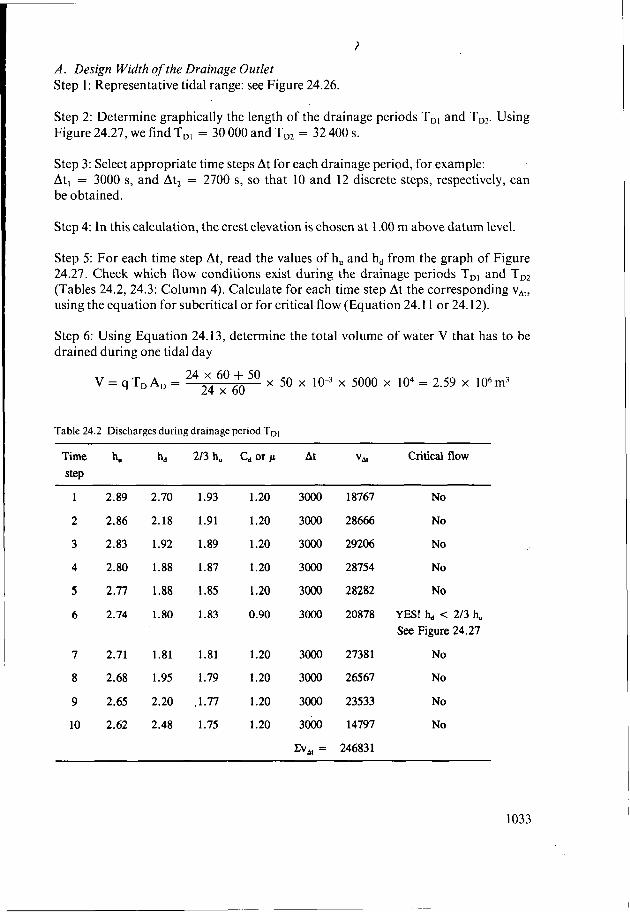
A . Design Width of the Drainage Outlet Step 1 : Representative tidal range: see Figure 24.26.
Step 2: Determine graphically the length of the drainage periods TDI and T,,. Using Figure 24.27, we find TDI = 30 O00 and TD, = 32 400 s.
Step 3: Select appropriate time steps At for each drainage period, for example: Atl = 3000 s, and At2 = 2700 s, so that 10 and 12 discrete steps, respectively, can be obtained.
Step 4: In this calculation, the crest elevation is chosen at 1 .O0 m above datum level.
Step 5: For each time step At, read the values of hu and h, from the graph of Figure 24.27. Check which flow conditions exist during the drainage periods TD, and T,, (Tables 24.2, 24.3: Column 4). Calculate for each time step At the corresponding vAt, using the equation for subcritical or for critical flow (Equation 24.1 1 or 24.12).
Step 6: Using Equation 24.13, determine the total volume of water V that has to be drained during one tidal day
24 -k 50 x 50 x x 5000 x lo4 = 2.59 x 10⁶m3 24 x 60 V = qTDAD =
Table 24.2 Discharges during drainage period TDI
Time hu h, 213 hu Cd or p At VAI critical flow SkP
1
2
3
4
5
6
7
8
9
10
2.89
2.86
2.83
2.80
2.77
2.74
2.71
2.68
2.65
2.62
2.70
2.18
1.92
1.88
1.88
1.80
1.81
1.95
2.20
2.48
1.93 1.20
1.91 1.20
1.89 1.20
1.87 1.20
1.85 1.20
1.83 0.90
1.81 1.20
1.79 1.20
,1.77 1.20
1.75 1.20
3000
3000
3000
3000
3000
3000
3000
3000
3000
3000
c v , =
18767
28666
29206
28754
28282
20878
2738 1
26567
23533
14797
24683 1
No
No
No
No
No
YES! < 213 hu See Figure 24.27
No
No
No
No
1033

< Table 24.3 Discharges during drainage period T D ~
Time step hu hd 213 hu c d Of p At VB critical flow
1
2
3
4
5
6
7
8
9
10
11
12
2.89 2.81 1.93 1.20
2.87 2.37 1.91 1.20
2.84 1.95 1.90 1.20
2.82 1.75 1.88 0.90
2.80 1.72 1.86 0.90
2.77 1.74 1.85 0.90
2.75 1.67 1.83 0.90
2.73 1.63 1.82 0.90
2.70 1.64 1.80 0.90
2.68 1.71 1.79 0.90
2.65 1.91 1.77 1.20
2.61 2.30 1.74 1.20
2700
2700
2700
2700
2700
2700
2700
2700
2700
2700
2700
2700
c v , =
11406
23970
2645 1
19619
19376
19134
18893
18653
18414
18176
23580
18378
23605 1
No
No
No
Yes
Yes
Yes
Yes
Yes
Yes
Yes
No
No
Step 7: Calculate the width of the outlet using Equation 24:14
- 5.36m = - V = 2.59 x 10⁶ Cvat (2.46 + 2.36) x lo5 -
Thus an outlet with two gates of 3 m each could be sufficient. Note: It is always preferred to apply an outlet with more than one opening for considerations of maintenance and repair.
B. Required Storage Capacity Step 8: During periods Tsl and TS2, water has to be stored because during those periods no drainage is possible. T,, has the longest duration: 3h50min.
Step 9: Determine the drainage discharge Q, by using Equation 24.15
Q = ‘l X AD = 24 50 3600 lo” x 5000 x lo4 = 28.9m3/s
Step 10: Using Equation 24.16, calculate the volume of water Vs that needs to be stored during the period T, (being the longest period)
V, = QT,, = 28.9 x (3 x 3600 + 50 x 60) = 0.40 x 10⁶m3
1034

Table 24.4 Reservoir analysis for the storage area. The required storage (Column 7) equals the accumulated inflow (Column 4) minus the accumulated outflow (Column 6)
1 2 3 4 5 6 7
Period Duration Inflow Cumulative outflow Cumulative Required (Step 9) inflow (Step 5 , 7) outflow storage
6) (m3 x lo6) (m3 x lo6) (m3 x lo6) (m3 x lo6) (m3 x 106)
Ts1 13800 0.40 0.40 0.00 0.00 0.40
TD1 30000 0.87 1.27 1.32 1.32 -0.05*
Ts, 13200 0.38 1.65 0.00 1.32 0.34
TD, 32400 0.94 2.59 1.27 2.59 0.00
* A negative value means that no storage is required
Step 11: Using Equation 24.17, calculate the average storage area A,
vs - ' O 6 = 1.33 x 10⁶m2 = 133 ha MASL-DDL - 3.90-3.60 A, =
Step 12: Because this calculation has been made for average tidal conditions, the advisable storage area should be 133 x 1.5 = 200 ha.
C. Checking the Calculations We can check the calculations by making a simple reservoir analysis for the drained area as is presented in Table 24.4.
It appears from Table 24.4 that, at the end of a tidal day, the volume of inflow is the same as that of the outflow, and that therefore, as was mentioned, the minimum storage volume should be 0.40 x lo6 m3.
Remarks on the Hydraulic Computation The hydraulic computation method that has been presented can be used as afirst approximation only, because the real situation has been simplified.
The first simplification was the value of the discharge coefficient p. There are no proper formulae from which can be derived satisfactorily. Therefore, for large outlet structures, the discharge coefficient needs to be investigated by scale models or by simulation; for smaller structures reference is made to Bos (1989).
Generally, the more open the gates, the less the contraction will be. If the gates could open completely and no part of them were to protrude significantly, the discharge coefficient could have values of 1 (which means no contraction at the gates) or, under favourable conditions, of even more than 1.
Other aspects to be mentioned are hydraulic losses at the transitions between channel and structure and losses due to friction along the sides of the structure. Table 24.5 gives a first indication of the values for the coefficient which takes these losses into account.
1035

Table 24.5 Head loss coefficients for hydraulic losses at the upstream and downstream transitions with the channel and for friction losses (Van der Kley and Zuidweg 1969)
Shape of side walls and crest ‘d
Crest elevation at channel bottom: - Sharp-cornered side walls 0.80
, - Rounded cornered side walls 0.90
0.72
= Sharp-cornered crest 0.76 = Rounded crest 0.85
Crest elevation above channel bottom: - Sharp-cornered crest and side walls - Rounded side walls:
Other simplifications used were: - A constant inflow rate equal to the drainage coefficient of the drained area; - An average tidal curve for one tidal day.
Reality is of course different and more complex. In principle, it is possible to simulate the real situation rather satisfactorily by using hydraulic computer models in which the system ‘inner water levels, storage, outlet structure, and outer water levels’ can be schematized in one network as follows: - Fluctuating inner water levels can be simulated on the basis of a design rainfall
or a series of measured rainfall data; - Fluctuating outer water levels can be simulated on the basis of the most important
constituents that influence daily water levels (tidal area), on seasonal river water levels (non-tidal area), or on a combination of the two (tidal rivers);
- Various areas of the storage reservoir can be included in the network; - The flow through the outlet as a result of the above-mentioned fluctuating water
levels. Several outlet characteristics (including varying contraction coefficients) could be used as input.
In this way, we can simulate the functioning of an outlet for a relatively longer period (e.g. a month to include spring and neap tides, or a season to include extreme river flows), and to test the sensitivity of some parameters to obtain an insight into the design conditions. An example of such a simulation model is ‘Drainage: Tidal Sluice Simulation’ (Standa Vanacek 1990), which demonstrates the hydraulic functioning of the system ‘drainage sluice, storage area, tidal outer water levels’. The model shows the sensitivity of design parameters (like storage area, crest width, and crest level) and the effect of numerical parameters (implicit versus explicit numerical solution methods, different time steps) on the design of a tidal drainage sluice.
A third element to be discussed is that the inner and outer waters have different densities (Figure 24.28). The doors of an outlet will remain closed as long as the forces acting upon them are in equilibrium.
Thus for equilibrium
1036
(24.18)


water level
I - outer water level
I I I I L I I I
time
discharge I I I
! ! I
time
Figure 24.29 Water level fluctuations and discharge of an outlet structure under tidal conditions
The best solution then is to choose the crest level at the elevation of the foreshore. Relatively high crest elevations also occur in drained areas with a relatively high ground level and a corresponding high DDL. In such cases, the crest elevation might be chosen at, or even above, low water level.
When outlets are located upstream of the tidal reach of a river, the crest level must be chosen at 1.50 to 1.75 m below DDL (provided, of course, that the river water levels allow free drainage).
Doors and Gates In tidal areas, either doors (with a vertical or horizontal axis) or sliding gates can be applied. In tidal areas, doors have the advantage of opening and closing by hydraulic forces only. Waves, however, may cause a repeated opening and closing, which not only allows outer water to intrude, but may also damage the doors and hinges. The gates should also be able to withstand the wave forces and should be able to pass these forces to their hinges.
The prevention of salt water intrusion via doors and gates can be realized by applying rubber profiles near the hinges and at the ends where they touch each other (or touch the side walls in case of only one door).
In non-tidal areas, sliding gates can better be applied, as they can still be opened when large differences between inner and outer water levels occur. Furthermore, it is possible to maintain higher inner water levels (when desired), which is not possible with outlet doors that open towards the outer water levels.
1038

To prevent a hampered operation of the outlet and to protect the doors and gates from damage by floating debris, trash-racks should be applied at the inner side to collect the debris.
Doors and gates can be maintained and repaired by closing the outlet temporarily with stoplogs, for which slots in the sidewalls are required in which the logs can slide. These slots should be provided at both sides of the gate to cope with varying inner and outer water levels.
In case of a tidal outlet, a second set of doors might be constructed, in order to ensure extra safety of the drained area against high outer waters.
The height of the doors should, of course, be at the same elevation as the dike, to prevent flooding during extremely high outer water levels.
For gravity outlets that consist of more than one opening, it is advisable to have the same dimensions for all openings. This will allow a standard design for the doors/ gates and for other mechanical items, and will make them exchangeable.
24.3.5 Other Aspects
As the tidal outlet is part of the protection system of an area, it should be constructed in such a way that it does not weaken this defence. This implies that seepage under the structure should be prevented, which can be realized by applying sheet piles. In case of relatively high outer water levels, it may even be necessary to apply sheet piles not only underneath the structure, but also next to both side walls.
High velocities through outlets should be avoided to prevent scouring and damage to banks and the structure itself (Chapter 19). This can be achieved by applying larger cross-sections for outlets and channels (resulting in lower velocities) and/or by lining the channel banks and protecting the outlet channel. On the other hand, sedimentation in the canals should be prevented by flushing the canals, for which certain minimum velocities are required.
Besides the problem of the intrusion of poor quality outer water, the quality of the drainage water is of increasing importance. As long as the quantity of polluted drainage water is small compared to the outer water, and the characteristics of the pollution allow for natural breakdown, no special measures need be taken. In areas where water of good quality is of importance, however, special measures might be needed, such as: - Removing/diminishing the source of contamination; - Restricting drainage from pollutive sources like industry, intensive agriculture; - Purifying polluted drainage water before discharging it to outer waters, which is
hardly feasible for drainage water that is polluted by agricultural practices; - Discharging the drainage water in smaller quantities. This measure will not only
require more storage, but is also related to the acceptability of storing polluted water in the drainage system;
- Discharging further downstream or at various locations. (Chapter 25 elaborates on water quality in further detail.)
When the outer channel is subject to sedimentation and siltation (tidal foreshores, rivers with high sediment loads), regular flushing and/or dredging might be required. In tidal areas, flushing can be realized by constructing the required storage reservoir
1039

water storage
water inner
Figure 24.30 Plan view of a storage reservoir, which is also used to flush the outer channel
next to the outlet structure (the outer doors) on the inland side, followed by a second set of doors (inner doors), which separate the reservoir from the drained area (Figure 24.30).
During normal operation, the outer doors open and close to allow for drainage, while the inner doors are kept open constantly. When flushing of the outer channel is required, the outer doors are kept open and the inner doors will close when the outer water levels become higher than the inner water levels. This will cause the water level in the storage area to rise to high water level. During the following drainage period, much more hydraulic head will be available, so that the outer channel can be flushed successfully. This, however, requires embankments encircling the storage area to offer protection against high outer water levels (Van der Kley and Zuidweg 1969; Smedema and Rycroft 1983).
References
Bos M.G. (ed.) 1989. Discharge measurement structures. ILRI Publication 20, Wageningen, 401 p. Chow V.T. 1959.Open-channel hydraulics. McGraw-Hill, New York, 680 p. Chow V.T. 1964. Handbook of applied hydrology. McGraw-Hill, London, 1418 p. De Vries, J.E., H. Lammers and A.P. Potma 1947-1951. De Technische Vraagbaak : Handboek in vijf
French, R.H. 1986. Open channel hydraulics. McGraw-Hill, New York, 705 p. Kalkwijk, J.P.Th. 1984. Tides. International Institute for Hydraulic and Environmental Engineering, Delft. Pugh, D.T. 1987. Tides, surges, and mean sea level. Wiley, New York, 472 p. Savenije, H. 1992. Rapid assessment technique for salinity intrusion in alluvial estuaries. International
Schureman, P. 1958. Manual of harmonic analysis and prediction of tides. Coast and Geodetic Survey,
Smedema, L.K. and D.W. Rycroft 1983. Land drainage : planning and design of agricultural drainage
Standa Vanecek 1990. Drainage : tidal sluice simulation. International Institute for Hydraulic and
U.S. Bureau of Reclamation 1983. Design of small dams. U.S. Bureau of Reclamation, Department of
Van der Kley, J. and H.J. Zuidweg 1969. Polders en dijken. Agon Elsevier, Amsterdam, 342 p. Van Os, A.G. and G. Abraham 1990. Density currents and salt intrusion. International Institute for
delen voor de gehele techniek. 5th ed. Volume W, Weg- en waterbouwkunde, Deventer.
Institute for Hydraulic and Environmental Engineering, Delft.
U.S. Department of Commerce, Special Publication No. 98, Washington, 317 p.
systems. Batsford, London, 376 p.
Environmental Engineering, Delft.
the Interior, Washington, 816 p.
Hydraulic and Environmental Engineering, Delft.
1040