Design of Future Software Defined Radio (SDR) for All … of Future Software Defined Radio (SDR) for...
10
12 Recent Patents on Signal Processing, 2010, 2, 12-21 1877-6124/10 2010 Bentham Open Open Access Design of Future Software Defined Radio (SDR) for All-IP Heterogeneous Network Md. Zahangir Alam *,1 and M. Abdus Sobhan *,2 1 Electronic and Telecommunication Engineering Department, Prime University, Dhaka, Bangladesh 2 School of Engineering and Computer Science (SECS), IUB, Dhaka, Bangladesh Abstract: The software defined radio (SDR) is the heart of the 4G mobile communication to access any network at any time basis. The different wireless networks such as cellular, codeless, wireless local area network (WLAN) having different band of frequency requires individual software to access any call. The SDR device requires more antennas and low noise amplifier (LNA) because it is impossible for single antenna and single band pass filter to operate at all the frequency bands. Large number of antennas, filter and amplifier increased the size of the device. The SDR scan the available network and download the required software from WLAN, memory card, PC server etc. The downloading creates some problem, such as the limited download speed and its reliability. In this paper, the authors study the architecture of SDR based on the recently proposed CI-OFDM multiplexing technique to operate all networks in a particular band-width. We also find the interference among different CI channels of the same and different networks. Finally, we discuss the calling procedure between one user of one network and another user under another network using IP address. Keywords: SDR, OFDM, heterogeneous network, 4G, CI-OFDM. I. INTRODUCTION The first public mobile telephone system known as Mobile Telephone System (MTS) was introduced in United States in 1946. To provide higher capacity, the cellular concept is introduced in which the operating area of the system was divided into a set of adjacent, non-overlapping cells. The first generation (1G) of cellular system supported the analog cell phones with the speeds up to 2.4 Kbps. To support digital signal, the second generation (2G) system was planned with speeds up to 64 Kbps. To meet the future bandwidth hungry services, the third generation (3G) wireless system was developed in 1990s, which provided the transmission speeds from 125 Kbps to 2 Mbps. Future of the mobile communication (Beyond 3G) will be towards an integrated system (Heterogeneous Network) which will produce a common packet switched, possibly IP-based, system to access different types of networks by a single user terminal. The fourth generation (4G) is a high speed wireless network that transmits multimedia and other data over the wire-line backbone network [1]. Future mobile communications will provide seamless services comprising IP-based network that supports seamless interoperation between different networks. The IP network provides a seamless global roaming service through inter-system handover designed to enable handover between terminals using different technologies and of different bandwidths and *Address correspondence to these authors at the Electronic and Telecommunication Engineering Department, Prime University, Dhaka, Bangladesh; E-mail: [email protected]; School of Engineering and Computer Science (SECS), IUB, Dhaka, Bangladesh; Tel: +880- 1915784614; Fax: +880-2-805 5647; E-mail: [email protected] frequencies [2]. To achieve this goal, vertical handover technology and SDR technologies are needed. The IP-based 4G heterogeneous networks provide data and multimedia services by an integrated terminal at any time and anywhere basis. The 4G networks provide higher data rates with significant reduction of interference at the receiver caused by the multi-path propagation through the channel, which targets the market of 2010 and beyond. About 84% of all mobile phone subscribers in Japan have upgraded from slower 2G mobile services to 3G for higher data rate. Around 2010, The Japanese mobile operators will introduce "Long Term Evolution (LTE)", services which are sometimes termed 3.9G or Super-3G. The 4G technologies are currently under development and testing. 4G services will be introduced to the markets in Japan around 2015 or later. NTT DoCoMo introduced the next generation of mobile communication technology in 2002, which has been called ‘4G (fourth generation)’. Samsung Electronics Co. Ltd. demonstrated 4G mobile technology at the annual Samsung 4G Forum in Korea with the data rate up to 60 Mbps in motion and 100 Mbps in stationary case. The 4G framework provides high speed wireless network that can transmit multimedia information with the required data rate. The problem to access different networks by an integrated user terminal is [3], a) it is impossible to have just one antenna and one LNA to serve the wide range of frequency bands and b) the slow downloading problem. To access different networks by a single user terminal, software radio receiver is proposed as in [4], in which a two dimensional CI-OFDM codes are assigned. The first dimensional CI-code is for the desired user and the second dimensional one is for the network in which the user is assigned. As a result, each antenna and amplifier accesses the whole frequency band as in OFDM technology according
Transcript of Design of Future Software Defined Radio (SDR) for All … of Future Software Defined Radio (SDR) for...

12 Recent Patents on Signal Processing, 2010, 2, 12-21
1877-6124/10 2010 Bentham Open
Open Access
Design of Future Software Defined Radio (SDR) for All-IP Heterogeneous Network
Md. Zahangir Alam*,1
and M. Abdus Sobhan*,2
1Electronic and Telecommunication Engineering Department, Prime University, Dhaka, Bangladesh
2School of Engineering and Computer Science (SECS), IUB, Dhaka, Bangladesh
Abstract: The software defined radio (SDR) is the heart of the 4G mobile communication to access any network at any
time basis. The different wireless networks such as cellular, codeless, wireless local area network (WLAN) having
different band of frequency requires individual software to access any call. The SDR device requires more antennas and
low noise amplifier (LNA) because it is impossible for single antenna and single band pass filter to operate at all the
frequency bands. Large number of antennas, filter and amplifier increased the size of the device. The SDR scan the
available network and download the required software from WLAN, memory card, PC server etc. The downloading
creates some problem, such as the limited download speed and its reliability. In this paper, the authors study the
architecture of SDR based on the recently proposed CI-OFDM multiplexing technique to operate all networks in a
particular band-width. We also find the interference among different CI channels of the same and different networks.
Finally, we discuss the calling procedure between one user of one network and another user under another network using
IP address.
Keywords: SDR, OFDM, heterogeneous network, 4G, CI-OFDM.
I. INTRODUCTION
The first public mobile telephone system known as Mobile Telephone System (MTS) was introduced in United States in 1946. To provide higher capacity, the cellular concept is introduced in which the operating area of the system was divided into a set of adjacent, non-overlapping cells. The first generation (1G) of cellular system supported the analog cell phones with the speeds up to 2.4 Kbps. To support digital signal, the second generation (2G) system was planned with speeds up to 64 Kbps. To meet the future bandwidth hungry services, the third generation (3G) wireless system was developed in 1990s, which provided the transmission speeds from 125 Kbps to 2 Mbps. Future of the mobile communication (Beyond 3G) will be towards an integrated system (Heterogeneous Network) which will produce a common packet switched, possibly IP-based, system to access different types of networks by a single user terminal.
The fourth generation (4G) is a high speed wireless network that transmits multimedia and other data over the wire-line backbone network [1]. Future mobile communications will provide seamless services comprising IP-based network that supports seamless interoperation between different networks. The IP network provides a seamless global roaming service through inter-system handover designed to enable handover between terminals using different technologies and of different bandwidths and
*Address correspondence to these authors at the Electronic and
Telecommunication Engineering Department, Prime University, Dhaka,
Bangladesh; E-mail: [email protected]; School of Engineering and
Computer Science (SECS), IUB, Dhaka, Bangladesh; Tel: +880-
1915784614; Fax: +880-2-805 5647; E-mail: [email protected]
frequencies [2]. To achieve this goal, vertical handover technology and SDR technologies are needed. The IP-based 4G heterogeneous networks provide data and multimedia services by an integrated terminal at any time and anywhere basis. The 4G networks provide higher data rates with significant reduction of interference at the receiver caused by the multi-path propagation through the channel, which targets the market of 2010 and beyond. About 84% of all mobile phone subscribers in Japan have upgraded from slower 2G mobile services to 3G for higher data rate. Around 2010, The Japanese mobile operators will introduce "Long Term Evolution (LTE)", services which are sometimes termed 3.9G or Super-3G. The 4G technologies are currently under development and testing. 4G services will be introduced to the markets in Japan around 2015 or later. NTT DoCoMo introduced the next generation of mobile communication technology in 2002, which has been called ‘4G (fourth generation)’. Samsung Electronics Co. Ltd. demonstrated 4G mobile technology at the annual Samsung 4G Forum in Korea with the data rate up to 60 Mbps in motion and 100 Mbps in stationary case. The 4G framework provides high speed wireless network that can transmit multimedia information with the required data rate.
The problem to access different networks by an integrated user terminal is [3], a) it is impossible to have just one antenna and one LNA to serve the wide range of frequency bands and b) the slow downloading problem. To access different networks by a single user terminal, software radio receiver is proposed as in [4], in which a two dimensional CI-OFDM codes are assigned. The first dimensional CI-code is for the desired user and the second dimensional one is for the network in which the user is assigned. As a result, each antenna and amplifier accesses the whole frequency band as in OFDM technology according

Design of Future SDR for All-IP Heterogeneous Network Recent Patents on Signal Processing, 2010, Volume 2 13
to the patent [5]. The contribution of the proposed system as in [4] is that single antenna and LNA can be designed to access all networks and users of each network by using two dimensional CI-codes in which each network and each user can be identified by corresponding CI-code. The two dimensional CI code which is used to multiplex different network and CI-OFDM requires the same bandwidth as OFDM but the CI codes provide different phase shift to different sub-carriers [6]. Hence all devices such as LNA and filter operate in the same band for all networks. In this paper, the authors attempt to discuss the architecture of SDR depending on the recent proposal to access any network by using single antenna and LNA through CI code. The capacity of the cellular system under single network and multiple networks is calculated. The cell structure for CI/OFDM based cellular system is discussed in this paper. The interference of different channel having individual CI-codes under the same network and different networks are calculated in terms of carrier to interference ratio (CIR) in the hexagonal cellular wireless system. Each network is identified by the sub-carrier frequency of OFDM symbol and the user channel is identified by CI-codes, while in GSM system, different channel has different frequency band and in CDMA system, different channel has different spreading (PN) codes. Finally the calling procedure between one user of one network and another user under another network is discussed using the carrier frequency of that particular network and the corresponding CI code of those users.
II. WHY 4G?
The main driver for 4G is data rate without any loss of user data after transmission through a noisy channel. 4G is a wireless link that provides very high data rate through a fading channel at data rate of 100 Mbps in moving environment and 1 Gbps in stationary condition. The development of integrated wireless network in 4G enables to connect several present and future wireless access technologies such as WLAN and cellular technologies like UMTS, EDGE, etc., and seamlessly move between all the networks under 4G platform using IP based wireless technology. 4G is developed to provide high data rate according to different user access networks such as wireless broadband access, Multimedia Messaging Service (MMS),Teleconferencing, video chat, mobile TV, IPTV, HDTV content, Digital Audio Broadcasting (DAB), Digital Video Broadcasting (DVB) etc.
The IP based 4G wireless heterogeneous system provides a new air interface that provides seamless operation with higher data rates with minimal error using OFDM based multiplexing technology. Basically, the 4G system accesses any types of network and provides a comprehensive IP solution based on Internet Protocol version 4 (IPV4), or Internet Protocol version 6 (IPV6), where voice, data and streamed multimedia can be given to users demands using OFDM technology.
III. SDR APPROACH
The SDR is a communication system that integrates different types of network in a common platform. It uses appropriate software for modulation and demodulation of the radio signals assigned to each network. The SDR produces a radio link that can receive and transmit a new form of radio
protocol by running the particular software. The SDR consists of a super-heterodyne RF section to convert RF signals to analog IF signals, and analog to digital converter and digital to analog converters which are used to convert a digitized IF signal from and to analog form [7]. The SDR technologies provide different technologies such as interference management and capacity enhancement over a broad frequency spectrum, with ensuring secure communications management.
IV. SIGNAL RECEPTION THROUGH SDR
SDR is the main device for a user terminal to access different network using individual IP address. Fig. (1) shows the design of an ideal software radio to access different networks [7, 8]. It consists of mainly two parts, one analog part and another digital part. The transmitted analog high frequency signal is down converted to lower frequency by super-heterodyne principle. The analog part consists of an antenna, a band-pass filter (BPF), and an LNA. At the digital part, the received analog signal is digitized by the analog to digital converter (ADC) immediately after the analog processing. The modulation, coding, security and other processing are performed in the next stage by a reprogrammable base-band digital signal processor (DSP). The problem of SDR is to access the whole bandwidth for all networks; because one antenna and one LNA cannot serve the wide range of frequency bands. To access the entire network the only solution is to use multiple analog parts to work in different frequency bands. This solution increases the design complexity and physical size of the terminal.
Fig. (1). An ideal software radio receiver [3].
V. SOFTWARE DOWNLOADING
Multimode user terminals should be able to select the target wireless systems. This process becomes complicated in 4G heterogeneous systems [8]. One of the solutions is to use software radio device that can scan the available network and load the required software and reconfigure themselves for the selected networks. Fig. (2) shows the attachment process of multimode terminal to a WLAN, which scans the available wireless networks, and after scanning, it downloads the required software. The software can be downloaded from the media such as a PC server, Smart card, or memory card, or over the air (OTA). As pointed out in [6], we still need to solve problems such as the deleterious, low downloading speed.
VI. OFDM BASICS
OFDM is the driving force of 4G wireless communication and is used in 4G with integrated WiMax to

14 Recent Patents on Signal Processing, 2010, Volume 2 Alam and Sobhan
provide higher data rate and large coverage area. OFDM also increases the spectrum efficiency. OFDM is based on a mathematical process called the Fast Fourier Transform (FFT), which provides the wireless channel to overlap without losing their individual characteristics (that maintain orthogonality between the sub-carriers). This provides efficient use of the spectrum and enables the channels to be processed at the receiver more efficiently. In OFDM, an incoming high data stream enters at the transmitter side. As seen in Fig. (3a), this incoming data is converted into serial to parallel form, the frequency domain data stream is converted into time domain by IFFT, and carrier spacing is carefully selected to ensure orthogonality between all sub-carriers. . It can download suitable software manually or automatically [8].
Fig. (2). A multimode terminal attached to the WLAN that scans
the available networks [9].
Fig. (3a). OFDM Transmitter.
Mathematically, the transmitted signal can be written as [10]:
S(t) = Xkej2 fkt
k=0
N
; t = [0,T ] . (1)
where, Xk,is the modulated complex data symbol and fk is sub-carrier frequency, and T is symbol period. At the receiver side, the incoming data stream is first returned to base-band by using the same sub-carrier frequency that is assigned to the transmitter. After converting the analog signal into digital, the cyclic prefix is removed. The serial data is then converted to parallel and a simple decision device is applied. Receiver implementation can be greatly simplified by use of an FFT to get the original transmitted symbol. The OFDM receiver structure is shown in Fig. (3b).
VII. CI/OFDM APPROACH
The OFDM is a multi-carrier system, where an incoming high data stream is mapped to N low rate stream and the carriers are combined together and sent out over the channel. In CI approach [6], at the heart of Carrier Interferometry technology lays the signal referred to as the Carrier Interferometry (CI) signal. The CI signal is very narrow, enabling it (1) to be easily separated from other CI signals,
and (2) to resolve the channel’s multi-path profiles. The CI signal is-
Denoted by c(t) and consist of N carriers in phase, each equally spaced by frequency separation f.
A frequency sampled with phase offset from carrier to carrier of the sinc(x) waveform.
An approximation to the sinc(x) waveform generated by frequency sampling the sinc(x) waveform using N equally spaced samples.
Fig. (3b). OFDM receiver.
A CI signal positioned with a main-lobe centered at time 0 is orthogonal to a CI signal with its mainlobe positioned at time , where is a value in the set {k/(N f), k=1,2,….N-1)}. This property assures that CI waveform can be applied to represent information symbols located sequentially in time, without creating inter-symbol interference.
VIII. NOVEL MULTIPLEXING TECHNIQUE TO ACCESS HETEROGENEOUS NETWORK
A number of antennas and Band pass filters (BF) are used at the Base Station (BS) to access different networks such as GSM, GPRS, CDMA, UMTS, and WLAN etc. Multiple analog parts are used in SDR to work in different frequency bands because each analog device is designed to work in a particular frequency band. The multiple analog parts increase the design complexity and physical size of the terminal, and decrease the switching time. The SDR device selects the target wireless systems by scanning the available network. Each network has unique software to process each call and the SDR after scanning a network, downloads the required software from the media such as a PC server, Smart card, or memory card, or over the air (OTA). The problem is the long downloading time and slow speed of data transfer [11].
In some recent works reported in [4, 12-14] the two
dimensional CI codes of the OFDM subcarriers are assigned
to each network and each user of each networks. The system
operated at the total transmission bandwidth and different CI
codes that is transmitting antenna transmits at the same
bandwidth with different CI codes. The transmitted signal
for the kth network (k=0, 1, 2… N-1) in the CI/OFDM based
transmitting system is [5]:
Sk (t) =1
NakigTk (t iT )e j2 (i f )t e ji k
i=0
N 1
. (2)
where, f = 1 /Tb (Tb is the bit rate), the sub-carrier
frequency separation and k = (2 / N )k is the phase offset
used to generate for k network spreading code. Considering
the entire N-networks, the CI/OFDM transmitted signal is:
S(t) =1
N k=0
N 1
ak igT k (t iT )e j2 (i f )t e j i k
i=0
N 1
(3)
Design of Future SDR for All-IP Heterogeneous Network Recent Patents on Signal Processing, 2010, Volume 2 15
The received signal is:
r(t) =1
N k=0
N 1
ki a ki g Tk(t iT )e j2 (i f )t e ji k e j ki+ n(t)i=0
N 1
(4)
where ki and ki are the fade parameter and phase offset
introduced into the ith carrier of k network by the frequency
selective Rayleigh fading channel, and )(tn is additive white
Gaussian noise (AWGN). After removing the sub-carrier
frequency and phase offset i k , the decision vector
r = (r0 , r1, r2 , ....., rN 1 ) becomes:
rkj =1
Nki ki + kj kj + ji ji cos i ( k j )
j=0, j k
N 1
j=0, j i
N 1
(5)
The second term is caused by:
(a) Inter-carrier interference (ICI) which occurs due to
Doppler frequency shift ( fD ) and,
(b) Inter-symbol interference (ISI) that occurs due to multi-path propagation.
In 4G heterogeneous network the user data is transmitted
by using OFDM based multiplexing technique [9]. At the
transmitting site, the serial binary information bits are
transmitted to the receiver end using OFDM-based
multiplexing technique. In the recent CI-based OFDM
multiplexing technique [9, 10, 15, 16], all sub-carrier
frequencies for each network share the same frequency band
[4, 12]. The CI codes such as, e j k , e j2 k , e j3 k , e j4 k and
e j5 k differentiate the transmitting signals corresponding to
each network.
IX. SYSTEM MODEL
OFDM technique can be written mathematically as [17]:
S(t) = X( p+q) (t) exp j2 f( p+q)tq=
N 1
p=0
M 1
, (6)
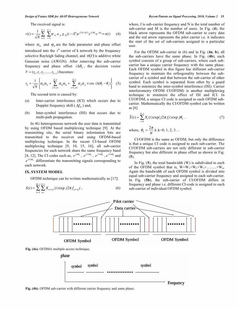
where, f is sub-carrier frequency and N is the total number of sub-carrier and M is the number of users. In Fig. (4), the black arrow represents the OFDM sub-carrier to carry data and the red arrow represents the pilot carrier i.e. it indicates the start of the set of sub-carriers assigned to a particular user.
For the OFDM sub-carrier in (6) and in Fig. (4a, b), all the sub-carriers have the same phase. In Fig. (4b), each symbol consists of a group of sub-carriers, where each sub-carrier has a unique carrier frequency with the same phase. Each OFDM symbol in this figure has different sub-carrier frequency to maintain the orthogonality between the sub-carrier of a symbol and that between the sub-carrier of other symbol. Each symbol is separated from other by a guard band to minimize the inter-symbol interference (ISI). Carrier interferometry OFDM CI/OFDM) is another multiplexing technique to minimize the effect of ISI and ICI. In CI/OFDM, a unique CI code is assigned to each OFDM sub-carrier. Mathematically the CI/OFDM symbol can be written as [6]
S (t) = Xi (t) exp( j2 fit) exp j ki=0
N 1
. (7)
where, k =2
Nk; k=0, 1, 2, 3…
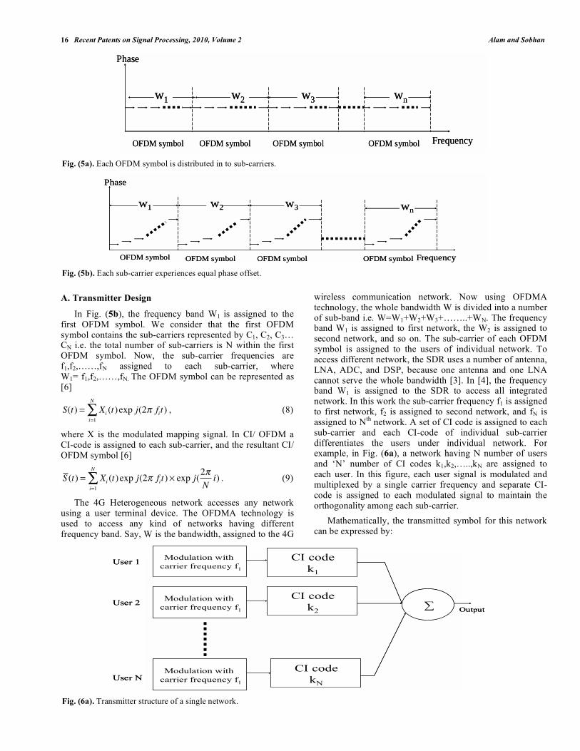
CI/OFDM is the same as OFDM, but only the difference is that a unique CI code is assigned to each sub-carrier. The CI/OFDM sub-carriers are not only different in sub-carrier frequency but also different in phase offset as shown in Fig. (5).
In Fig. (5), the total bandwidth (W) is subdivided to each of the OFDM symbol that is, W=W1+W2+W3+……..+Wn. Again the bandwidth of each OFDM symbol is divided into equal sub-carrier frequency and assigned to each sub-carrier. In Fig. (5b), the sub-carrier of CI/OFDM differs in frequency and phase i.e. different CI-code is assigned to each sub-carrier of individual OFDM symbol.
Fig. (4a). OFDMA multiple access technique.
Fig. (4b). OFDM sub-carrier with different carrier frequency and same phase.
Pilot carrier
Data carrier
OFDM Symbol OFDM Symbol OFDM Symbol
Pilot carrier
Data carrier
OFDM Symbol OFDM Symbol OFDM Symbol
phase
Frequency
symbol symbol symbol
phase
Frequency
symbol symbol symbol
16 Recent Patents on Signal Processing, 2010, Volume 2 Alam and Sobhan
A. Transmitter Design
In Fig. (5b), the frequency band W1 is assigned to the first OFDM symbol. We consider that the first OFDM symbol contains the sub-carriers represented by C1, C2, C3… CN i.e. the total number of sub-carriers is N within the first OFDM symbol. Now, the sub-carrier frequencies are f1,f2,……,fN assigned to each sub-carrier, where W1= f1,f2,……,fN. The OFDM symbol can be represented as [6]
S(t) = Xi (t) exp j(2 fit)i=1
N
, (8)
where X is the modulated mapping signal. In CI/ OFDM a CI-code is assigned to each sub-carrier, and the resultant CI/ OFDM symbol [6]
S (t) = Xi (t) exp j(2 fit)i=1
N
exp j(2
Ni) . (9)
The 4G Heterogeneous network accesses any network using a user terminal device. The OFDMA technology is used to access any kind of networks having different frequency band. Say, W is the bandwidth, assigned to the 4G
wireless communication network. Now using OFDMA technology, the whole bandwidth W is divided into a number of sub-band i.e. W=W1+W2+W3+……..+WN. The frequency band W1 is assigned to first network, the W2 is assigned to second network, and so on. The sub-carrier of each OFDM symbol is assigned to the users of individual network. To access different network, the SDR uses a number of antenna, LNA, ADC, and DSP, because one antenna and one LNA cannot serve the whole bandwidth [3]. In [4], the frequency band W1 is assigned to the SDR to access all integrated network. In this work the sub-carrier frequency f1 is assigned to first network, f2 is assigned to second network, and fN is assigned to N
th network. A set of CI code is assigned to each
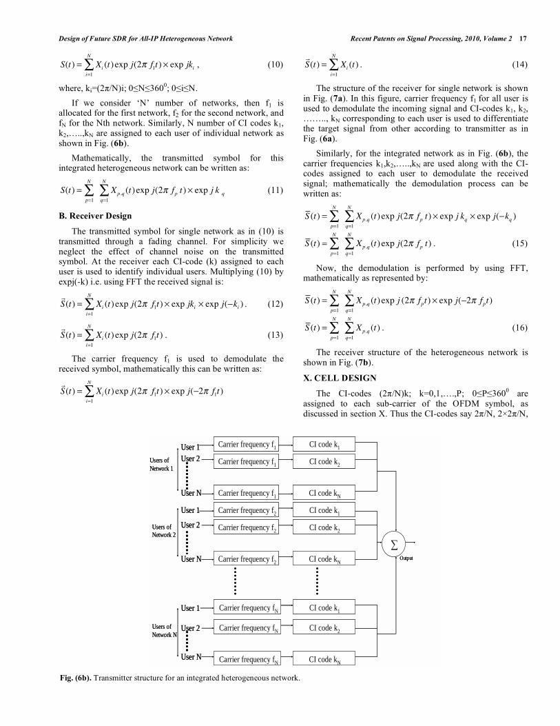
sub-carrier and each CI-code of individual sub-carrier differentiates the users under individual network. For example, in Fig. (6a), a network having N number of users and ‘N’ number of CI codes k1,k2,…..,kN are assigned to each user. In this figure, each user signal is modulated and multiplexed by a single carrier frequency and separate CI-code is assigned to each modulated signal to maintain the orthogonality among each sub-carrier.
Mathematically, the transmitted symbol for this network can be expressed by:
Fig. (6a). Transmitter structure of a single network.
Fig. (5a). Each OFDM symbol is distributed in to sub-carriers.
Fig. (5b). Each sub-carrier experiences equal phase offset.
w1 w2 w3 wn
Phase
FrequencyOFDM symbol OFDM symbol OFDM symbol OFDM symbol
w1 w2 w3 wn
Phase
FrequencyOFDM symbol OFDM symbol OFDM symbol OFDM symbol
Frequency
Phase
w1 w2 wnw3
OFDM symbol OFDM symbol OFDM symbol OFDM symbol Frequency
Phase
w1 w2 wnw3
OFDM symbol OFDM symbol OFDM symbol OFDM symbol
User 1Modulation with
carrier frequency f1
CI codek1
User 2Modulation with
carrier frequency f1
CI codek2
User NModulation with
carrier frequency f1
CI codekN
∑ Output
User 1Modulation with
carrier frequency f1
CI codek1
User 2Modulation with
carrier frequency f1
CI codek2
User NModulation with
carrier frequency f1
CI codekN
∑ Output
Design of Future SDR for All-IP Heterogeneous Network Recent Patents on Signal Processing, 2010, Volume 2 17
S(t) = Xi (t) exp j(2 f1t) exp jkii=1
N
, (10)
where, ki=(2 /N)i; 0 N 3600; 0 i N.
If we consider ‘N’ number of networks, then f1 is allocated for the first network, f2 for the second network, and fN for the Nth network. Similarly, N number of CI codes k1, k2,…..,kN are assigned to each user of individual network as shown in Fig. (6b).
Mathematically, the transmitted symbol for this integrated heterogeneous network can be written as:
S(t) =p=1
N
Xp,q (t) exp j(2 fp t) exp j k qq=1
N
(11)
B. Receiver Design
The transmitted symbol for single network as in (10) is transmitted through a fading channel. For simplicity we neglect the effect of channel noise on the transmitted symbol. At the receiver each CI-code (k) assigned to each user is used to identify individual users. Multiplying (10) by expj(-k) i.e. using FFT the received signal is:
S(t) = Xi (t) exp j(2 f1t) exp jkii=1
N
exp j( ki ) . (12)
S(t) = Xi (t) exp j(2 f1t)i=1
N
. (13)
The carrier frequency f1 is used to demodulate the received symbol, mathematically this can be written as:
S(t) = Xi (t) exp j(2 f1t)i=1
N
exp j( 2 f1t)
S(t) = Xi (t)i=1
N
. (14)
The structure of the receiver for single network is shown in Fig. (7a). In this figure, carrier frequency f1 for all user is used to demodulate the incoming signal and CI-codes k1, k2, …….., kN corresponding to each user is used to differentiate the target signal from other according to transmitter as in Fig. (6a).
Similarly, for the integrated network as in Fig. (6b), the carrier frequencies k1,k2,…..,kN are used along with the CI-codes assigned to each user to demodulate the received signal; mathematically the demodulation process can be written as:
S (t) =p=1
N
Xp,q (t) exp j(2 fp t) exp j kqq=1
N
exp j( kq )
S (t) =p=1
N
Xp,q (t) exp j(2 fp t)q=1
N
. (15)
Now, the demodulation is performed by using FFT, mathematically as represented by:
S (t) =p=1
N
Xp,q (t) exp j (2 fpt)q=1
N
exp j( 2 fpt)
S (t) =p=1
N
Xp,q (t)q=1
N
. (16)
The receiver structure of the heterogeneous network is shown in Fig. (7b).
X. CELL DESIGN
The CI-codes (2 /N)k; k=0,1,….,P; 0 P 3600 are
assigned to each sub-carrier of the OFDM symbol, as discussed in section X. Thus the CI-codes say 2 /N, 2 2 /N,
Fig. (6b). Transmitter structure for an integrated heterogeneous network.
Output
User 1User 2
User N
User 1
User 2
User N
User 1
User 2
User N
Carrier frequency f1
Carrier frequency f1
Carrier frequency f1
Carrier frequency f2
Carrier frequency f2
Carrier frequency f2
Carrier frequency fN
Carrier frequency fN
Carrier frequency fN
CI code k1
CI code k2
CI code kN
CI code k1
CI code k2
CI code kN
CI code k1
CI code k2
CI code kN
Users of Network 1
Users of Network 2
Users of Network N

18 Recent Patents on Signal Processing, 2010, Volume 2 Alam and Sobhan
3 2 /N… ……, P 2 /N are used to make P phase shift carrier. The P numbers of phase shift carriers are used to identify P numbers of users and the carrier frequency is any sub-carrier frequency of the OFDM symbol. The number of network is the same as the number of sub-carriers (in this design scheme 0 N 360) is then the maximum number of networks that can be accessed by the OFDM multiplexing technology is N. Hence, the number of channel in any network is P and the total number of channel in the Heterogeneous network is PN. Among the P channel of each network, most of the channels are used as traffic channel and rest of them are used as control channel. Consider a cellular system for any single network which has a total of P channels. If a cell is allocated a group of k channels (k<P), and if the P channels are divided among N cells, then the total number of radio channel can be expressed as P=kN. If the cluster of size ‘N’ is replicated M times within the same network, then the capacity of the cellular system with a single network is C=MKN. Now, if the cellular system consists of R different network with N channels of each network, then the overall capacity of the cellular system is C’=RMkN=RC.
Hence, the capacity of our proposed model is ‘R’ times the the capacity of any cellular system, where R is the total number of sub-carriers of the OFDM symbol. As in Fig. (8), there are four networks in the cellular system. Frequency f1 is allocated for the network A, f2 is allocated for the network B, f3 is allocated for the network C and f4 is allocated for the network D.
For 7-cell reuse system each network having 7 cells that is the cluster size is 7. A network has cluster A1, A2, A3, A4, A5, A6 and A7. Similarly, other networks B, C and D have seven clusters as shown in Fig. (8). The method of locating different co-channel cells is shown in Fig. (8). The number of cells N per cluster satisfies the following relation [10]:
Fig. (7a). Receiver structure for a single network.
N = (i + p)2 + (i + p) ( j + q) + ( j + q)2 . (17)
where, i,p,q and j are non-negative integer number. Here i is the number of cells of the core network, whose channel should be reused and p is the number of cells of another neighbor network along any chain of hexagons and can be found according to [18]. The interference between two channels k and (k+m) of a network having carrier frequency f is [19]:
C(t) = ej2
N(k+m+ )
0
T
ej2
Nkdt
= T cos2
N(m + ) . (18)
where, is the phase shift at the received OFDM symbol due to multi-path fading effect of the channel. The interference
Fig. (7b). Receiver structure of a heterogeneous network.
User 1Demodulation with carrier frequency f1
CI codek1
User 2Demodulation with carrier frequency f1
CI codek2
User NDemodulation with carrier frequency f1
CI codekN
From noisy channel
User 1Demodulation with carrier frequency f1
CI codek1
User 2Demodulation with carrier frequency f1
CI codek2
User NDemodulation with carrier frequency f1
CI codekN
From noisy channel
User 1User 2
User N
User 1
User 2
User N
User 1
User 2
User N
Carrier frequency f1
Carrier frequency f1
Carrier frequency f1
Carrier frequency f2
Carrier frequency f2
Carrier frequency f2
Carrier frequency fN
Carrier frequency fN
CI code k1
CI code k2
CI code kN
CI code k1
CI code k2
CI code kN
CI code k1
CI code k2
Carrier frequency fN CI code kN
Signal
From noisy channel
Users of Network 1
Users of Network 2
Users of Network N

Design of Future SDR for All-IP Heterogeneous Network Recent Patents on Signal Processing, 2010, Volume 2 19
between the two channels of two networks having the same CI codes, and the carrier frequency of two networks is f1 and f2 respectively, then the interference can be written as:
C(t) = exp j2 ( f1 f2 )t dt0
T
C(t) = sin 2 ( f1 f2 )t dt0
T
C(t) =1
2 ( f1 f2 )cos 2 ( f1 f2 ) (19)
Fig. (8). Locating co-channel cell.
Now, the interference of two channels have k and (k+m) CI-codes, and if the two channels are in two different network of carrier frequency f1 and f2, then the interference is:
C '(t) = e j2 f1t
0
T
e j2 f2t ej2
N(k+m )
ej2
Nkdt
C '(t) = ej2
Nm
e j2 ( f1 f2 )t
0
T
dt
C '(t) = cos2
Nm
1
2 ( f1 f2 )cos 2 ( f1 f2 )T . (20)
For a single network the CI-OFDM symbol with p=1, we have from (11)
s(t) = Xqq=1
N
(t) exp j (2 f1 t + kq ) . (21)
Now, consider the 1st sub-carrier as target signal (C) and
all other as interference signal (I), we have
C = X1(t) exp j (2 f1t) exp j k1 , (22)
I = Xqq=2
N
(t) exp j (2 f1 t + kq ) . (23)
If all the sub-carrier transmit the same power and received from the same distance then the CIR) is:
C
I=
exp j k1
exp j kqq=2
N . (24)
The CIR for same CI-code sub-carrier, in this case single k
th sub-carrier of one symbol as desired signal and rest N-1
as interference signal, we have
C = X1(t) exp j (2 f1t) exp j k (25)
I = Xqq=1,q k
N
(t) exp j (2 fq t + k ) (26)
For the same transmitting power and received distance, we have:
C
I=
exp j 2 fkt
exp j 2 fqtq=1,q k
N . (27)
Now, CIR for CI-code of different networks, we have,
C
I=
exp j (2 fkt + kk )
p=1,p k
N
exp j (2 fp,qt + kp,q )q=1,q k
N (28)
XI. NETWORK DESIGN
The 4G wireless network use IPv6 based IP address, which consist of permanent “home” IP address and a dynamic “care-of” address that represent the location of the mobile station [1]. The OFDM multiplexing technique can be used to transfer the data packet from one network to another network through internet and the user of each network is identified by unique IP address. In our proposed case, the sub-carrier frequency identifies the individual network and the CI codes of each network identify the users of each network, and finally the IP packet from any user of one network can be transferred to another user of other network by using the sub-carrier frequencies of each network and CI-codes of each user. The IPV6 contains the address of the network and the address of the user under the network by using 128 bits that is 128 bits unique address is assigned to each user under all network. As in Fig. (9), consider three networks, namely A, B and C. The carrier frequency of A is f1, that of B is f2 and that of C is f3. Each network has two users and each user has individual IP address. Say, user 1 of network A likes to send data to the user 1 of network C. At first the network A assigns a CI code to the user 1 and the user 1 of network A sends the data to network A using the carrier frequency f1 and the CI code assigned to user 1. Network A knows the IP address of the user 1 of network C and forwards the request to the network C. Network C forwards the request to its user 1 by using the carrier frequency f3 and the CI code assigned to its user 1.
XII. RESULT
The BER performance of CI/OFDM symbol is discussed in [6] with the number of CI-codes under a multi-path fading environment. That is, BER increases with the number of users in a network. Again it is shown that the BER decreases with the

20 Recent Patents on Signal Processing, 2010, Volume 2 Alam and Sobhan
separation of the sub-carrier frequency of the OFDM symbol. Hence, BER performance can be improved by reusing the CI-channels of neighboring networks having highest separation of carrier frequency among the networks. The interference between the CI-channels of the same network is shown in Fig. (10) with the carrier phase offset of 0.001, 0.1, 0.5 and 0.9.
It is seen in Fig. (10) that the interference increases with the carrier phase shift due to fading effects. Fig. (11) shows that the CIR due to the number of unwanted signal interferes with the desired signal in a network. It is seen in Fig. (11) that the number of interferer signal decreases the network performance because the interference signal loses the desire signal strength. The interference signal increases with the number of unwanted signal and the logarithm of the ratio of the desired signal strength to the interference signal gives the negative sign of the CIR which is expressed in dB. Hence, interference can be reduced by reusing the sub-carrier frequencies of neighbor networks. In the works [4, 12-14], the authors assign different
sub-carrier frequency to each user, which decreases the network capacity. In this paper, the same sub-carrier frequency is assigned to each user of a network and CI-codes are assigned to each user to increase the CIR performance.
XIII. CONCLUSION
Our proposed CI/OFDM based heterogeneous cellular system provides better capacity with sharing less channel bandwidth than the traditional OFDMA based cellular system as discussed in section XI. Our proposed model reduces the size of the SDR device; hence the software for different network can be stored to its memory card. This avoids the downloading of any required software to access a call from other network, say WLAN, Internet, or PC server etc. Hence, the operating speeds of SDR can be increased in this CI/OFDM based 4G cellular system. The CI-code based channel assignment technique in this paper provides better network performance in terms of CIR than the works in [4, 12-14].
Fig. (9). Basic 4G network architecture scheme.
Fig. (10). Interference component between the CI-channels within a network.
Network A:Carrier frequency f1
IP network
Network B:Carrier frequency f2
Network C:Carrier frequency f3
User 1 User 2 User 2
User 2
User 1
User 1
Network A:Carrier frequency f1
IP network
Network B:Carrier frequency f2
Network C:Carrier frequency f3
User 1 User 2 User 2
User 2
User 1
User 1
0 1 2 3 4 5 6 7 8 9 100.0196
0.0197
0.0197
0.0198
0.0198
0.0199
0.0199
0.0199
0.02
0.02
Difference in CI index(degree)
I(in
terfer
ence
)
phase offset=0.001
phase offset=0.1
phase offset=0.5phase offset=0.9

Design of Future SDR for All-IP Heterogeneous Network Recent Patents on Signal Processing, 2010, Volume 2 21
REFERENCES
[1] Huang SL. Evolution from 3G to 4G and beyond (5G). ITN-620
enterprise network design. International Conference on Information Technology Las Vegas, Nevada, USA July 2005.
[2] ETSI TR 101957 v 1.1.1. Requirements and Architectures for Interworking between HIPERLAN/2 and 3rd Generation cellular
system. [3] Hui SY, Yeung KH. Challenges in the migration to 4g mobile
systems. IEEE Commun Mag 2003; 54-59. [4] Alam MZ, Islam CS, Sobhan MA. A Novel idea to combat 4G
challenges to establish all wireless internet services. Proceedings of IEEE International Symposium on Broadband Multimedia Systems
and Broadcasting (BTS 2008), Las Vegas Hilton, Las Vegas, NV, USA 31 March-2 April 2008 .
[5] Roh, H.J., Kim, M.G., Lee, S.J.: WO Patent 7089121A1, 2007; EP Patent 1816769A2, 2007.
[6] Nassar CR, Natarajan B, Wu Z, Wiegandt D, Zekavat SA, Shattil S. Multi-carrier technologies for wireless communication.
Massachuscttes: Kluwer Academic Publishers 2002. [7] Tuttlebee W. Software defined radio-enabling technologies.
Malden, MA, USA: John Wiley & Sons 2002. [8] Buracchini E. The software radio concept. IEEE Commun Mag
2000; 38(9): 138-43. [9] Katz M, Fitzek FHP. Cooperative technique and principles
enabling future 4G wireless networks. EUROCON Glasgow, Scotland, November 22-24, 2005.
[10] Bahai ARS, Saltzberg BR. Multi-carrier digital communications: theory and applications of OFDM. New York: Kluwer Academic
Publishers 1999. [11] Le TH, Aghvami AH. Performance of an accessing and allocation
scheme for the download channel in software radio. Proceedings of IEEE Wireless Communication and Networking Conference, Cape
Town, South Africa 2000; 2: pp. 517-21.
[12] Alam MZ, Alom MZ, Sobhan MA. All-IP 4G wireless networks for
future wireless and internet services. Proceedings of the Indian Conference on Microwaves, Antenna, Propagation and Remote
Sensing, Jodhpur, India 9-11 December, 2008. {13] Alam MZ, Alom MZ, Sobhan MA. Network design of novel
multiplexing approach of SDR based 4G wireless networks. Proceedings of the1st International Conference on Computer,
Communication, Control and Information Technology (C3it-2009), Hoogly, India, Feb 2009.
[14] Alam MZ, Patra CC, Patra C, Sobhan MA. Multiplexing technique for All-IP heterogeneous network. Proceedings of the 5
th
Advanced International Conference on Telecommunication (AICT-2009), Venice, Italy May 24-28, 2009.
[15] Han SH, Lee JH. Peak to average power ratio reduction of an OFDM signal by signal set expansion. IEEE international
conference, Mannheim, Germany 20-24 June, 2004; vol. 2: pp. 867-71.
[16] Alam MZ, Alom MZ, Hossain MA, Sobhan MA. Cross correlation and PAPR analysis of frequency shuffled sub-carrier based
CI/OFDM modulation system for fading channels. Proceedings of the IEEE WOCN 2008, Surabaya, East Java, Indonesia May 5-7,
2008. [17] Andrews JG, Ghosh A, Muhamed R. Fundamentals of WiMAX-
understanding broadband wireless networking. New Jersey: Prentice Hall 2007.
[18] Rappaport TS. Wireless communications: principles and practices. IEEE Press: New Jersey, Prentice Hall 2003.
[19] Alam MZ, Alom MZ, Molla MKI, Sobhan MA. Orthogonal frequency division multiplexing (OFDM) based multi-path channel
modeling using sub-carrier frequency shuffling to reduce ISI and ICI effect. Proceedings of the 14th IEEE Asia pacific conference on
communication, Tokyo, Japan October 14-16, 2008.
Received: June 16, 2009 Revised: July 20, 2009 Accepted: October 14, 2009
© Alam and Sobhan; Licensee Bentham Open.
This is an open access article licensed under the terms of the Creative Commons Attribution Non-Commercial License (http://creativecommons.org/licenses/by-
nc/3.0/) which permits unrestricted, non-commercial use, distribution and reproduction in any medium, provided the work is properly cited.
Fig. (11). CIR component due to the interference from the unwanted signal.