Design of Extrusion Heads - Politechnika Lubelskabc.pollub.pl/Content/101/Design of Extrusion...
64
Janusz Sikora Department of Polymer Processing Lublin University of Technology Design of Extrusion Heads 1. Introduction The extrusion head is the processing tool that shapes the extrudate i.e. the tool that determines shape, properties, structures and dimensions of the extrudate as well as mutual position of the elements in the extrusion process. The extrusion head is the tool with an open forming cavity i.e. the extrusion die. The extrusion head has to ensure the occurrence of proper physical and chemical processes in the polymer during its flow through the flow channels [65, 67]. The extrusion head is fixed to the end part of the plasticizing system of the extruder. Small extrusion heads are fixed mainly by means of bolt connections or bolt-pin connections (usually hinge-type connections) or by means of a screwed shape ring. Larger extrusion heads are fixed by means of bolt-pin connections, shape semi-rings that are attached and fixed with bolts as well as by means of bolt connections that are very often provided with a vertical support on the extruder foundation. More and more frequently, auxiliary preparatory devices such as a polymer filter, a gear pump or a static mixer (or a set of two or three such devices) are attached and fixed to the plasticizing system. The extrusion head, usually provided with a vertical support, is connected to the last preparatory supplementary device.
Transcript of Design of Extrusion Heads - Politechnika Lubelskabc.pollub.pl/Content/101/Design of Extrusion...
Janusz Sikora
Department of Polymer Processing
Lublin University of Technology
Design of Extrusion Heads
1. Introduction
The extrusion head is the processing tool that shapes the extrudate i.e. the tool that
determines shape, properties, structures and dimensions of the extrudate as well as
mutual position of the elements in the extrusion process. The extrusion head is the tool
with an open forming cavity i.e. the extrusion die. The extrusion head has to ensure the
occurrence of proper physical and chemical processes in the polymer during its flow
through the flow channels [65, 67].
The extrusion head is fixed to the end part of the plasticizing system of the extruder.
Small extrusion heads are fixed mainly by means of bolt connections or bolt-pin
connections (usually hinge-type connections) or by means of a screwed shape ring.
Larger extrusion heads are fixed by means of bolt-pin connections, shape semi-rings that
are attached and fixed with bolts as well as by means of bolt connections that are very
often provided with a vertical support on the extruder foundation. More and more
frequently, auxiliary preparatory devices such as a polymer filter, a gear pump or a static
mixer (or a set of two or three such devices) are attached and fixed to the plasticizing
system. The extrusion head, usually provided with a vertical support, is connected to the
last preparatory supplementary device.
2
Design of the extrusion head, regardless of its purpose, should take into account the
following general requirements that guarantee correct extrudate production process. The
above-mentioned requirements are as follows [59, 65, 67]:
ensuring proper polymer flow in the flow channels so as to obtain required shape
and dimensions of the extrudate,
enabling the extrusion process characterized by the highest possible polymer flow
intensity,
preventing polymer stagnation areas in the extrusion head by ensuring proper
shape and geometric characteristics of the flow channels and ensuring adequate
polymer flow resistance,
ensuring proper mixing and homogenisation of polymer as well as stabilization of
pressure at an adequately high level,
ensuring adequate strength of specific design elements of the extrusion head and
their connections in high pressure and temperature conditions,
ensuring adequate weight and compactness of design of the extrusion head due to
required thermal stability and guaranteeing the lowest number of partition
surfaces due to required leaktightness of the extrusion head,
protecting surfaces of the flow channels against aggressive impact of some
polymers,
providing the possibility of adjustment of polymer flow rate from the extrusion
head die if recommended extrusion process conditions are to be influenced,
especially the conditions inside the extrusion head,
Numerous extrusion head designs have been developed (including patented ones)
that differ with regard to design of specific functional components of the extrusion head,
operation mode, methods of polymer supply to the extrusion die and the purpose [24, 44,
67].
Extrusion heads can be categorized into two groups depending on the type of
extrudate obtained and the position of the extrusion head die with regard to the
plasticizing system. The first group includes the extrusion heads for profile (circular and
non-circular), blown film, flat film and sheet, for coating, pelletizing and blow moulding.
The second group includes the longitudinal extrusion heads (straight type) with polymer
3
inlet and outlet located on one axis coinciding with the plasticizing system axis, the
angular (skew type) extrusion heads with the polymer inlet on the plasticizing system axis
located at an angle with regard to the polymer outlet axis and the transverse extrusion
heads (cross type) with the polymer inlet and outlet located perpendicularly with regard to
each other. Considering the polymer flow direction with regard to the axis of the extrusion
head main body, the following types of extrusion heads can be distinguished: longitudinal,
angular, transverse and spiral extrusion heads [67]. The spiral extrusion heads can be
made as longitudinal as well as transverse ones.
Solid or foam polymer extrudates can be obtained in the extrusion process
performed by means of extrusion heads. The extrusion heads for solid polymers and the
extrusion heads for foam polymers can be distinguished since they differ slightly with
regard to their design.
Assuming the type of extrusion process as the categorization criterion, the following
types of extrusion heads can be distinguished: single-polymer extrusion heads used for
extruding a single polymer and multi layers extrusion heads used for simultaneous
extrusion of several polymers (single polymer having various properties or colours).
With regard to operation mode, the extrusion heads are categorized into the continuous
operation (standard heads) extrusion heads and the cyclical operation extrusion heads
(accumulator heads). However, in some cases, only a precise name, comprising within
its meaning the criteria mentioned above, can unequivocally define and characterize in
general the extrusion head, e.g. cross-type, three-polymer, cyclical operation extrusion
head for blow moulding of containers.
The extrusion head design comprises several functional units that are defined on the
basis of their tasks performed in the extrusion head. They are as follows: the shaping unit
(including the extrusion head die) that determines shape and cross-section dimensions of
the extrudate while taking into account the processing shrinkage phenomenon (primary
and secondary shrinkage) and swelling; the integrating unit that combines the extrusion
head with the plasticizing system barrel; the flow channels unit (inlet and polymer
distributing channels and sometimes separating channels); the heating unit with a tempe-
rature measuring and adjusting system; the unit of the setting, centring and connecting
elements; the supplementary unit i.e. for example the drive unit of the rotating mandrel or
4
die or the hydraulic piston that extrudes the polymer from the accumulator of the
extrusion head [53, 67].
The common feature of all the extrusion head designs is that each extrusion head has
a parallel polymer flow zone i.e. a die that has constant gap dimensions. In this zone,
relaxation of stresses and deformations of the plasticized polymer occur as well as
dimensions and characteristics of extrudate, especially those of its surface layer, are
established in steady temperature conditions.
2. Extrusion heads for profiles
The extrusion head for profiles form the biggest group of extrusion heads and are
most commonly used. The extrusion heads of this type are used for pipes, rods, flat bars,
window and door profiles, profiles for furniture industry (for plate finishing), profiles for
building industry (cable covering profiles and finishing profiles) and many others. The
extrusion head for pipes is most commonly used (it may be longitudinal, transverse as
well as helical) since pipes are produced in the biggest number. Profiles that have cross-
section other than circular are most frequently extruded with the use of the longitudinal
extrusion head.
2.1. Circular extrusion head
The longitudinal extrusion head for profiles of a circular cross-section differs mainly
with regard to the method of fixing the mandrel to the extrusion head body. It has been
assumed that the longitudinal extrusion heads used for extruding PVC pipes are
characterized by fixing the mandrel to the head body by means of spider legs positioned
symmetrically on the circumference of the extrusion head body. Diagram of such
extrusion head is shown on Figure 1.
Plasticized polymer is delivered from the plasticizing system of the extruder to the
extrusion head through the inlet flow channel that has, most frequently, a circular cross-
section and is coaxial with the plasticizing system. Polymer stream flows through the
polymer filter and having met the torpedo of the extrusion head mandrel flows into the
distributing channel (annular, conical, divergent, linear channel). Next, polymer flows
into the distributing flow channels formed by the spider legs where the polymer is
5
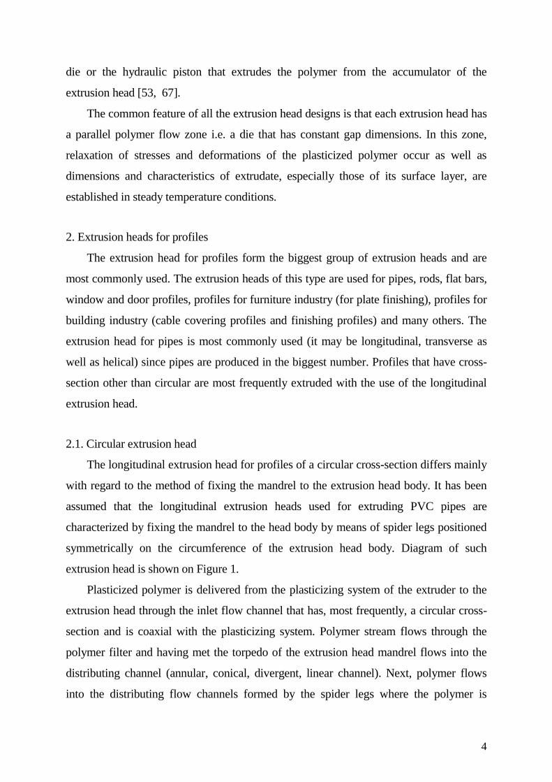
divided into several component streams and flows in parallel to the extrusion head axis.
The component streams flows into the distributing channel (annular, conical, convergent,
linear channel) where they connect. Finally, the polymer stream is introduced into the
extrusion head die (annular, linear channel that is characterized by a high ratio between
its length and transverse dimension and has a slightly changeable or, more frequently,
unchangeable cross-section). The polymer flows out of the die in the form of annular
stream that has cross-section dimensions close to cross-section dimensions of the pipes
produced.
Fig. 1. Diagram of the longitudinal extrusion head for pipes: 1 – inlet channel, 2 –
distributing channel, 3 – extrusion head die, 4 – supplementary channel that supplies air
to inside of the pipe, 5 – extrusion head body, 6 – die body, 7 – torpedo of the extrusion
head mandrel, 8 – extrusion head mandrel, 9 – polymer filter
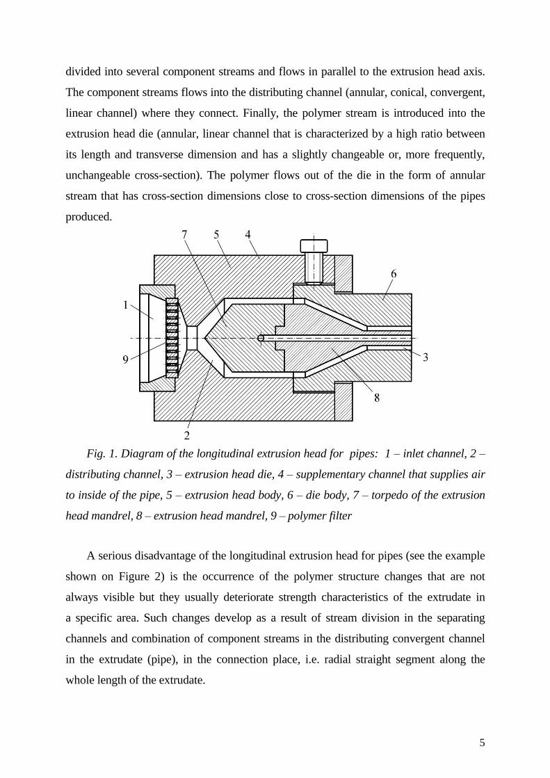
A serious disadvantage of the longitudinal extrusion head for pipes (see the example
shown on Figure 2) is the occurrence of the polymer structure changes that are not
always visible but they usually deteriorate strength characteristics of the extrudate in
a specific area. Such changes develop as a result of stream division in the separating
channels and combination of component streams in the distributing convergent channel
in the extrudate (pipe), in the connection place, i.e. radial straight segment along the
whole length of the extrudate.
6
Fig. 2. Longitudinal extrusion head for pipes (Hans Weber Maschinenfabrik,
Germany)
Development of specific joints in the places where component streams connect may
be caused by a considerable orientation of plasticized polymer in the vicinity of spider
legs. This orientation results from a high speed gradient occurring in the parietal zone of
plasticized polymer stream. The high speed gradient is produced by the parietal effect [27,
63] and results from stretching of polymer macroparticles located in the vicinity of the
ribs. Another cause of structural differences (that makes difficult remixing of polymer)
occurring in the places where component streams connect may be the polymer density
differences caused by the difference of temperatures between flowing polymer and spider
legs.
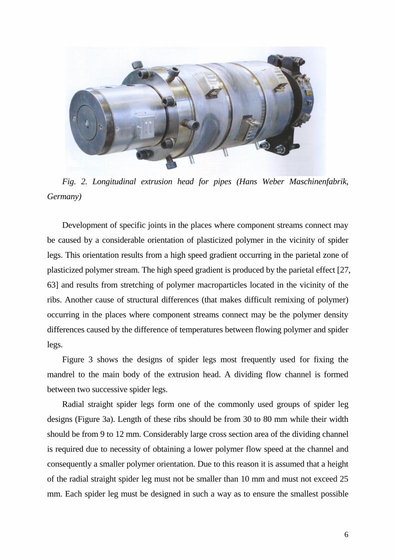
Figure 3 shows the designs of spider legs most frequently used for fixing the
mandrel to the main body of the extrusion head. A dividing flow channel is formed
between two successive spider legs.
Radial straight spider legs form one of the commonly used groups of spider leg
designs (Figure 3a). Length of these ribs should be from 30 to 80 mm while their width
should be from 9 to 12 mm. Considerably large cross section area of the dividing channel
is required due to necessity of obtaining a lower polymer flow speed at the channel and
consequently a smaller polymer orientation. Due to this reason it is assumed that a height
of the radial straight spider leg must not be smaller than 10 mm and must not exceed 25
mm. Each spider leg must be designed in such a way as to ensure the smallest possible
7
disturbance of plasticized polymer flow. The shape of the spider legs is recommended to
be as streamlined as possible and their number should be from three, four in small
extrusion heads to more than ten in larger extrusion heads. It is also important to select
the biggest diameter of the extrusion head mandrel and the diameter of the mandrel at the
outlet from the extrusion head. The ratio between these two values, in case of
longitudinal extrusion heads for PVC pipes, should be within the range from 1.4 to 1.6,
while in case of the extrusion heads for pipes made of polyolefines the ratio should be
about 2. In case of large longitudinal extrusion heads, slightly lower values of the
diameter ratio are allowable, i.e. respectively 1.25 for the extrusion heads for PVC pipes
and 1.4 for the extrusion heads for pipes made of polyolefines [39, 44].
Fig. 3. Spider legs designs: a) straight radial ribs, b) helical radial spider legs, c)
shape spider legs, d) arc radial spider legs; 1 – main body of the extrusion head, 2 –
torpedo of the extrusion head mandrel, 3 – dividing channel, 4 – spider legs [44, 67]
Helical radial spider legs are another design of spider legs used in the longitudinal
extrusion heads (Fig. 3b). Spider legs shaped in such a way change the shape of the
connection line between the component streams from the radial straight segment to the
helical segment of a larger length. Consequently, a smaller decrease of the pipe strength
8
parameters (caused by joints) is achieved. However, the helical radial spider legs are
relatively rarely used due to their very complicated manufacturing.
Sometimes, shape spider legs are used for fixing mandrels in the extrusion heads
(Fig. 3c) that are made in the carrying ring in such a way as to form the sections of the
annular dividing channel. When such spider legs are used the decrease of the pipe
strength parameters is small because the connection line between the component streams
does not run along the whole radius but only along its sections that are additionally
shifted with regard to each other. While shaping in a proper way the dividing channels
formed by the shape spider legs, care must be taken to ensure the same resistance of
polymer flow through all the channel sections and consequently, the same speed of the
plasticized polymer.
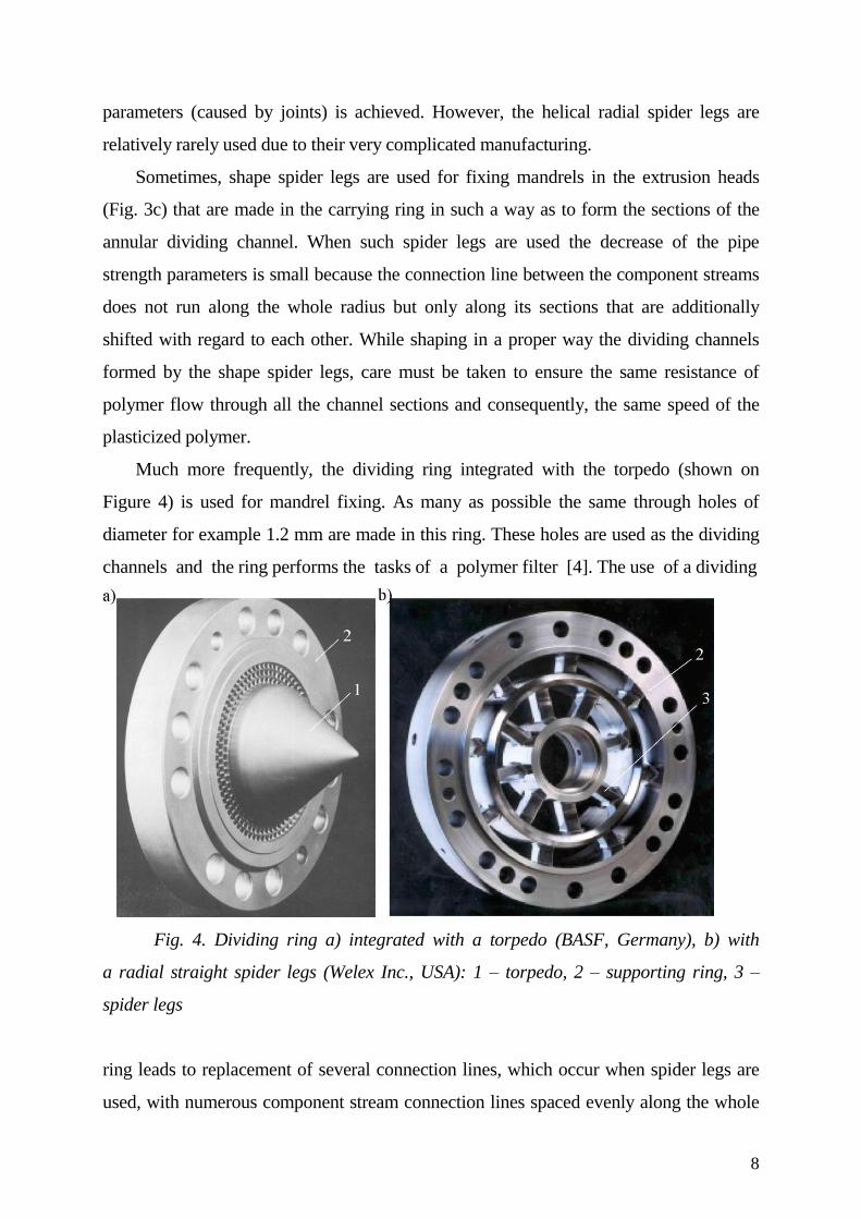
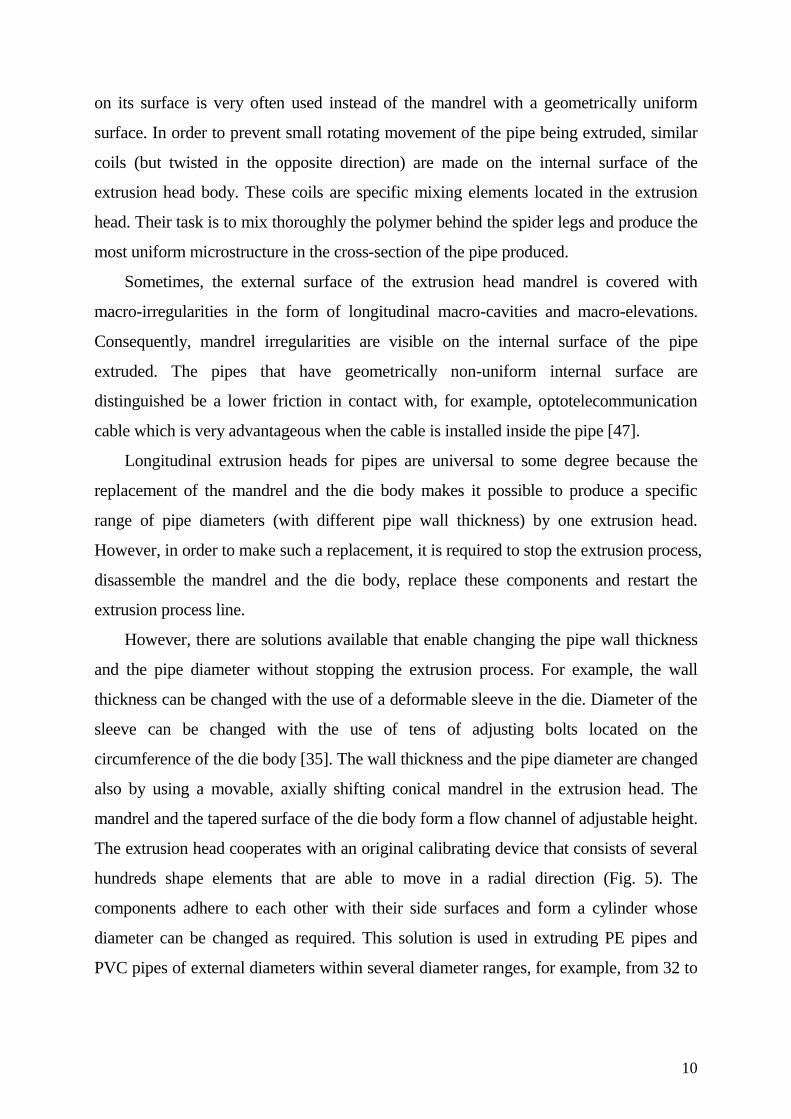
Much more frequently, the dividing ring integrated with the torpedo (shown on
Figure 4) is used for mandrel fixing. As many as possible the same through holes of
diameter for example 1.2 mm are made in this ring. These holes are used as the dividing
channels and the ring performs the tasks of a polymer filter [4]. The use of a dividing
Fig. 4. Dividing ring a) integrated with a torpedo (BASF, Germany), b) with
a radial straight spider legs (Welex Inc., USA): 1 – torpedo, 2 – supporting ring, 3 –
spider legs
ring leads to replacement of several connection lines, which occur when spider legs are
used, with numerous component stream connection lines spaced evenly along the whole
9
cross-section of the extruded pipe. Consequently, harmful influence of several
connection lines is restricted.
When extruding a profile of a closed cross-section (for example a pipe),
a supplementary channel is recommended to be made in the extrusion head to provide
a low-pressure supply of air during extrusion process. Such a solution prevents formation
of a reduced pressure area inside the profile as well as prevents the wall collapse.
A supplementary channel can be easily made in radial straight spider legs.
In order to reduce unfavourable impact of component stream connection lines that
occur in the stream connection areas, numerous modifications of the longitudinal
extrusion head designs are applied that consist in the following [44, 59]:
– using rotating elements of the extrusion head mandrel. However, in this case an
additional drive unit is required as well as the extrusion head must be protected against
undesirable polymer leakage,
– coating the spider legs with anti-adhesion materials such as for example (PTFE),
however, such coatings are quickly worn out in the conditions occurring in the extrusion
head,
– lengthening the polymer flow route in the extrusion head (after the passage of
polymer through the dividing channels) that is achieved by making flow channels which
change the polymer stream flow direction. Such a solution makes the extrusion head
much more difficult to make and expensive as well as may cause excessive polymer
pressure drop in the flow channels,
– heating of spider legs; in this case quite complicated design solutions are
required due to small dimensions of the ribs.
Design of the extrusion head mandrel should be planned in such a way as to ensure
that the mandrel reduces unfavourable impact of the connection line between the
component streams of polymer. For example, while reducing the diameter of the annular
distributing channel, the height of the channel is being reduced simultaneously.
Consequently, it is recommended that the inclination angle of the external surface of the
channel should be bigger than the inclination angle of the internal surface of the channel,
while the inclination angle of the internal surface of the channel should be within the
range from 10 to 15 deg. The mandrel with several or more than ten small-pitch flights
10
on its surface is very often used instead of the mandrel with a geometrically uniform
surface. In order to prevent small rotating movement of the pipe being extruded, similar
coils (but twisted in the opposite direction) are made on the internal surface of the
extrusion head body. These coils are specific mixing elements located in the extrusion
head. Their task is to mix thoroughly the polymer behind the spider legs and produce the
most uniform microstructure in the cross-section of the pipe produced.
Sometimes, the external surface of the extrusion head mandrel is covered with
macro-irregularities in the form of longitudinal macro-cavities and macro-elevations.
Consequently, mandrel irregularities are visible on the internal surface of the pipe
extruded. The pipes that have geometrically non-uniform internal surface are
distinguished be a lower friction in contact with, for example, optotelecommunication
cable which is very advantageous when the cable is installed inside the pipe [47].
Longitudinal extrusion heads for pipes are universal to some degree because the
replacement of the mandrel and the die body makes it possible to produce a specific
range of pipe diameters (with different pipe wall thickness) by one extrusion head.
However, in order to make such a replacement, it is required to stop the extrusion process,
disassemble the mandrel and the die body, replace these components and restart the
extrusion process line.
However, there are solutions available that enable changing the pipe wall thickness
and the pipe diameter without stopping the extrusion process. For example, the wall
thickness can be changed with the use of a deformable sleeve in the die. Diameter of the
sleeve can be changed with the use of tens of adjusting bolts located on the
circumference of the die body [35]. The wall thickness and the pipe diameter are changed
also by using a movable, axially shifting conical mandrel in the extrusion head. The
mandrel and the tapered surface of the die body form a flow channel of adjustable height.
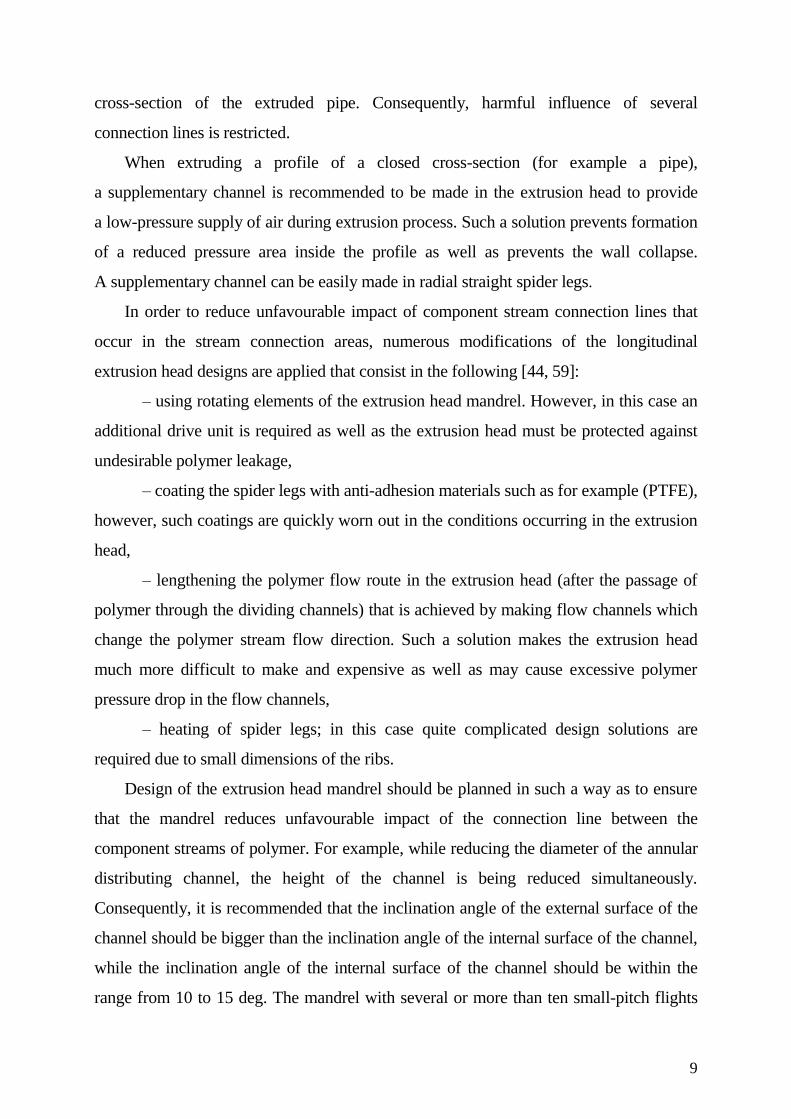
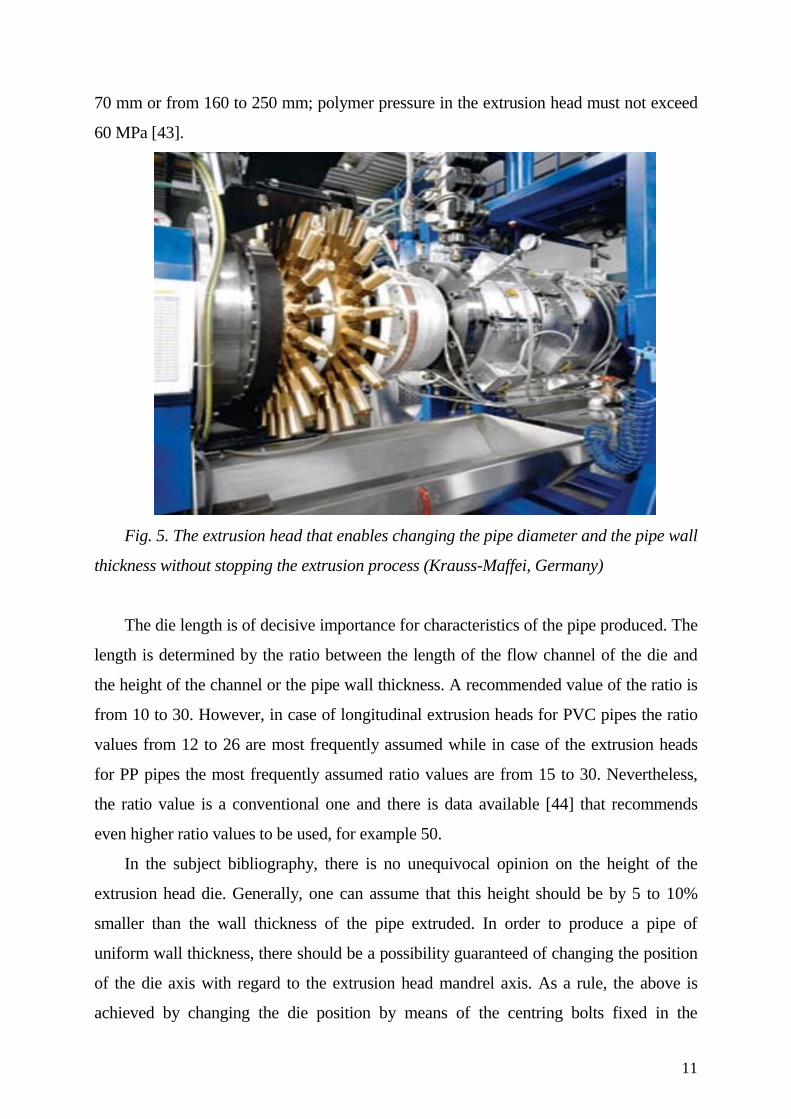
The extrusion head cooperates with an original calibrating device that consists of several
hundreds shape elements that are able to move in a radial direction (Fig. 5). The
components adhere to each other with their side surfaces and form a cylinder whose
diameter can be changed as required. This solution is used in extruding PE pipes and
PVC pipes of external diameters within several diameter ranges, for example, from 32 to
11
70 mm or from 160 to 250 mm; polymer pressure in the extrusion head must not exceed
60 MPa [43].
Fig. 5. The extrusion head that enables changing the pipe diameter and the pipe wall
thickness without stopping the extrusion process (Krauss-Maffei, Germany)
The die length is of decisive importance for characteristics of the pipe produced. The
length is determined by the ratio between the length of the flow channel of the die and
the height of the channel or the pipe wall thickness. A recommended value of the ratio is
from 10 to 30. However, in case of longitudinal extrusion heads for PVC pipes the ratio
values from 12 to 26 are most frequently assumed while in case of the extrusion heads
for PP pipes the most frequently assumed ratio values are from 15 to 30. Nevertheless,
the ratio value is a conventional one and there is data available [44] that recommends
even higher ratio values to be used, for example 50.
In the subject bibliography, there is no unequivocal opinion on the height of the
extrusion head die. Generally, one can assume that this height should be by 5 to 10%
smaller than the wall thickness of the pipe extruded. In order to produce a pipe of
uniform wall thickness, there should be a possibility guaranteed of changing the position
of the die axis with regard to the extrusion head mandrel axis. As a rule, the above is
achieved by changing the die position by means of the centring bolts fixed in the
12
extrusion head body or in a special centring ring. Position of the extrusion head die is
changed in the course of the extrusion process.
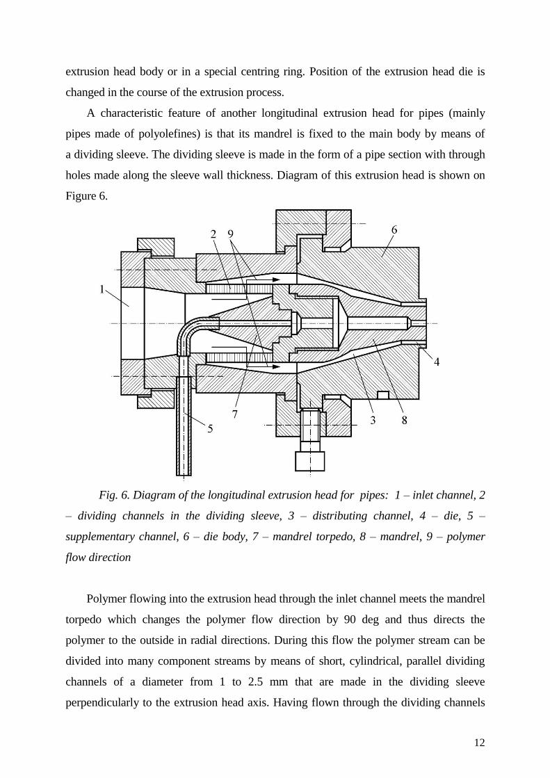
A characteristic feature of another longitudinal extrusion head for pipes (mainly
pipes made of polyolefines) is that its mandrel is fixed to the main body by means of
a dividing sleeve. The dividing sleeve is made in the form of a pipe section with through
holes made along the sleeve wall thickness. Diagram of this extrusion head is shown on
Figure 6.
Fig. 6. Diagram of the longitudinal extrusion head for pipes: 1 – inlet channel, 2
– dividing channels in the dividing sleeve, 3 – distributing channel, 4 – die, 5 –
supplementary channel, 6 – die body, 7 – mandrel torpedo, 8 – mandrel, 9 – polymer
flow direction
Polymer flowing into the extrusion head through the inlet channel meets the mandrel
torpedo which changes the polymer flow direction by 90 deg and thus directs the
polymer to the outside in radial directions. During this flow the polymer stream can be
divided into many component streams by means of short, cylindrical, parallel dividing
channels of a diameter from 1 to 2.5 mm that are made in the dividing sleeve
perpendicularly to the extrusion head axis. Having flown through the dividing channels
13
formed by the through-holes of the sleeve, the component streams of polymer get into the
annular distributing channel and meet the tapered surface of the internal wall of the
extrusion head body. The above leads to another change of polymer flow direction by 90
deg and simultaneous quite an intensive mixing of component streams caused by
combination of component streams and a violent change of their flow direction. Further
flow of polymer in the distributing channel is performed in a similar way as described
above.
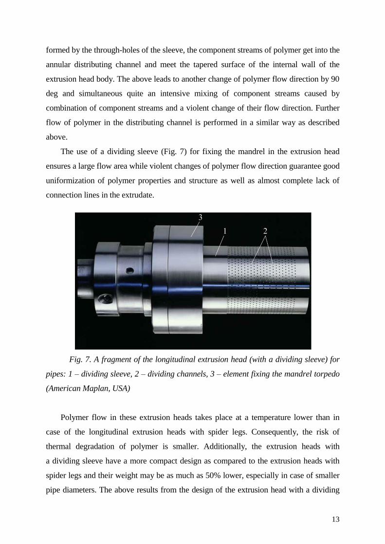
The use of a dividing sleeve (Fig. 7) for fixing the mandrel in the extrusion head
ensures a large flow area while violent changes of polymer flow direction guarantee good
uniformization of polymer properties and structure as well as almost complete lack of
connection lines in the extrudate.
Fig. 7. A fragment of the longitudinal extrusion head (with a dividing sleeve) for
pipes: 1 – dividing sleeve, 2 – dividing channels, 3 – element fixing the mandrel torpedo
(American Maplan, USA)
Polymer flow in these extrusion heads takes place at a temperature lower than in
case of the longitudinal extrusion heads with spider legs. Consequently, the risk of
thermal degradation of polymer is smaller. Additionally, the extrusion heads with
a dividing sleeve have a more compact design as compared to the extrusion heads with
spider legs and their weight may be as much as 50% lower, especially in case of smaller
pipe diameters. The above results from the design of the extrusion head with a dividing
14
sleeve in case of which the ratio between the biggest mandrel diameter and the mandrel
diameter at the outlet from the extrusion head may amount to 1.4, i.e. is lower than in the
longitudinal extrusion heads with spider legs [2].
The longitudinal extrusion head with a dividing sleeve is characterized by
a considerably lower value of total polymer pressure drop within the range from 7 to 12
MPa. The biggest value of total pressure drop at which these extrusion heads may be used
is within 25 ÷ 30 MPa. The longitudinal extrusion heads with a dividing sleeve may be
used for pipes of a small diameter, for example 10 mm. These extrusion heads also prove
effective in pipes of medium diameters, for example 450 mm, characterized by mass rate
of flow of 800 kg/h. Weight of the extrusion head used for such pipes is 1900 kg. These
extrusion heads are also used for pipes of large diameter amounting to 1400 mm. In the
last-mentioned case the extrusion head may be as heavy as 25000 kg and the amount of
polymer flowing through the head is 1200 kg/hour [2].
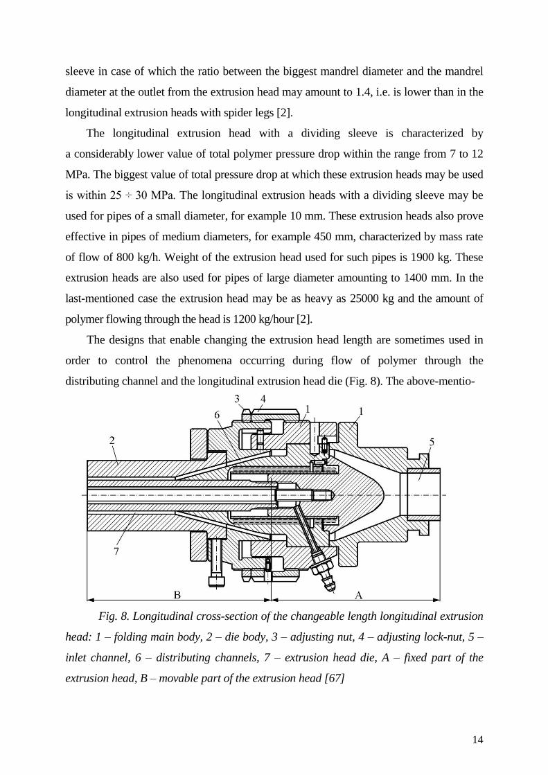
The designs that enable changing the extrusion head length are sometimes used in
order to control the phenomena occurring during flow of polymer through the
distributing channel and the longitudinal extrusion head die (Fig. 8). The above-mentio-
Fig. 8. Longitudinal cross-section of the changeable length longitudinal extrusion
head: 1 – folding main body, 2 – die body, 3 – adjusting nut, 4 – adjusting lock-nut, 5 –
inlet channel, 6 – distributing channels, 7 – extrusion head die, A – fixed part of the
extrusion head, B – movable part of the extrusion head [67]
15
ned solution changes mainly the length of polymer flow route and related conditions
concerning flow of polymer through the distributing channels and the extrusion head die.
The length may be also adjusted to the process needs conditioned by various types of
polymers being extruded.
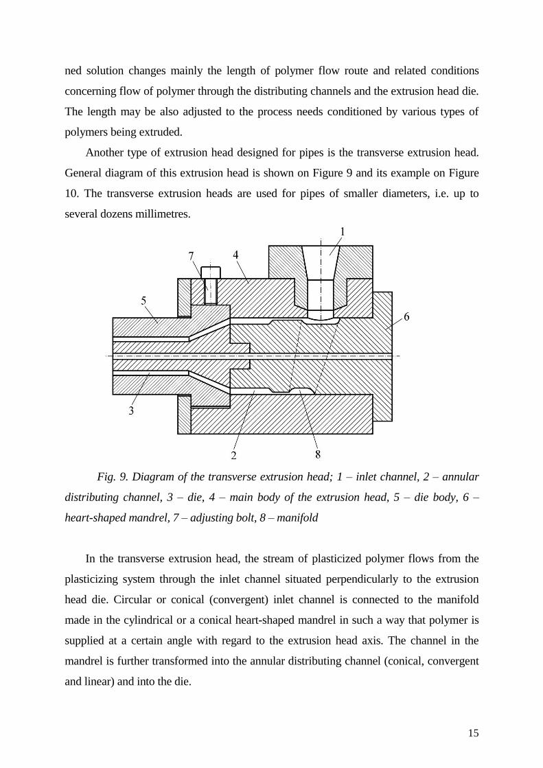
Another type of extrusion head designed for pipes is the transverse extrusion head.
General diagram of this extrusion head is shown on Figure 9 and its example on Figure
10. The transverse extrusion heads are used for pipes of smaller diameters, i.e. up to
several dozens millimetres.
Fig. 9. Diagram of the transverse extrusion head; 1 – inlet channel, 2 – annular
distributing channel, 3 – die, 4 – main body of the extrusion head, 5 – die body, 6 –
heart-shaped mandrel, 7 – adjusting bolt, 8 – manifold
In the transverse extrusion head, the stream of plasticized polymer flows from the
plasticizing system through the inlet channel situated perpendicularly to the extrusion
head die. Circular or conical (convergent) inlet channel is connected to the manifold
made in the cylindrical or a conical heart-shaped mandrel in such a way that polymer is
supplied at a certain angle with regard to the extrusion head axis. The channel in the
mandrel is further transformed into the annular distributing channel (conical, convergent
and linear) and into the die.
16
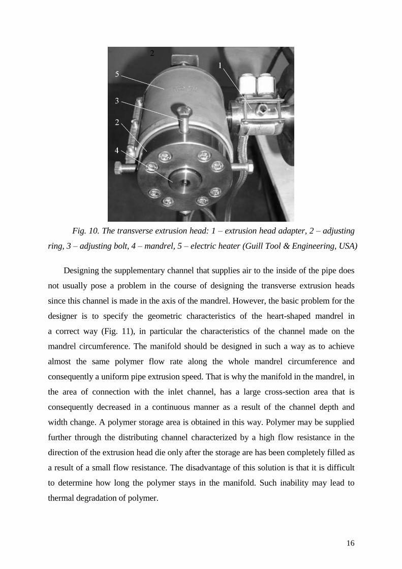
Fig. 10. The transverse extrusion head: 1 – extrusion head adapter, 2 – adjusting
ring, 3 – adjusting bolt, 4 – mandrel, 5 – electric heater (Guill Tool & Engineering, USA)
Designing the supplementary channel that supplies air to the inside of the pipe does
not usually pose a problem in the course of designing the transverse extrusion heads
since this channel is made in the axis of the mandrel. However, the basic problem for the
designer is to specify the geometric characteristics of the heart-shaped mandrel in
a correct way (Fig. 11), in particular the characteristics of the channel made on the
mandrel circumference. The manifold should be designed in such a way as to achieve
almost the same polymer flow rate along the whole mandrel circumference and
consequently a uniform pipe extrusion speed. That is why the manifold in the mandrel, in
the area of connection with the inlet channel, has a large cross-section area that is
consequently decreased in a continuous manner as a result of the channel depth and
width change. A polymer storage area is obtained in this way. Polymer may be supplied
further through the distributing channel characterized by a high flow resistance in the
direction of the extrusion head die only after the storage are has been completely filled as
a result of a small flow resistance. The disadvantage of this solution is that it is difficult
to determine how long the polymer stays in the manifold. Such inability may lead to
thermal degradation of polymer.
17
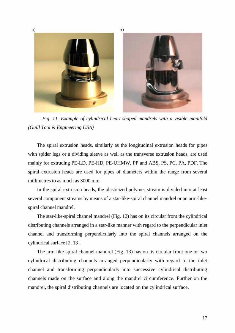
Fig. 11. Example of cylindrical heart-shaped mandrels with a visible manifold
(Guill Tool & Engineering USA)
The spiral extrusion heads, similarly as the longitudinal extrusion heads for pipes
with spider legs or a dividing sleeve as well as the transverse extrusion heads, are used
mainly for extruding PE-LD, PE-HD, PE-UHMW, PP and ABS, PS, PC, PA, PDF. The
spiral extrusion heads are used for pipes of diameters within the range from several
millimetres to as much as 3000 mm.
In the spiral extrusion heads, the plasticized polymer stream is divided into at least
several component streams by means of a star-like-spiral channel mandrel or an arm-like-
spiral channel mandrel.
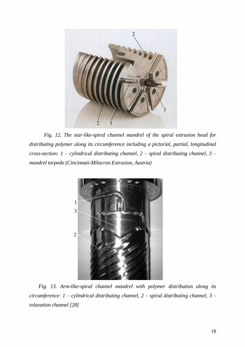
The star-like-spiral channel mandrel (Fig. 12) has on its circular front the cylindrical
distributing channels arranged in a star-like manner with regard to the perpendicular inlet
channel and transforming perpendicularly into the spiral channels arranged on the
cylindrical surface [2, 13].
The arm-like-spiral channel mandrel (Fig. 13) has on its circular front one or two
cylindrical distributing channels arranged perpendicularly with regard to the inlet
channel and transforming perpendicularly into successive cylindrical distributing
channels made on the surface and along the mandrel circumference. Further on the
mandrel, the spiral distributing channels are located on the cylindrical surface.
18
Fig. 12. The star-like-spiral channel mandrel of the spiral extrusion head for
distributing polymer along its circumference including a pictorial, partial, longitudinal
cross-section: 1 – cylindrical distributing channel, 2 – spiral distributing channel, 3 –
mandrel torpedo (Cincinnati-Milacron Extrusion, Austria)
Fig. 13. Arm-like-spiral channel mandrel with polymer distribution along its
circumference: 1 – cylindrical distributing channel, 2 – spiral distributing channel, 3 –
relaxation channel [28]
19
Depending on the spiral extrusion head size, several up to more than ten or
sometimes several dozens of spiral channel flights are made on the mandrel [29]. Depth
of spiral channels in the star-like-spiral mandrel is most frequently decreased until its
disappearance in the direction of the die while the height of the gap between the upper
surface of the coil and the internal surface of the extrusion head body increases
continuously. Thus, polymer in the area where the channels are the deepest flows only
through the spiral channel. However, as polymer gets nearer to the die, i.e. as the channel
depth decreases, increasing amount of polymer starts flowing also through the gap
between the channel flight and the extrusion head body surface.
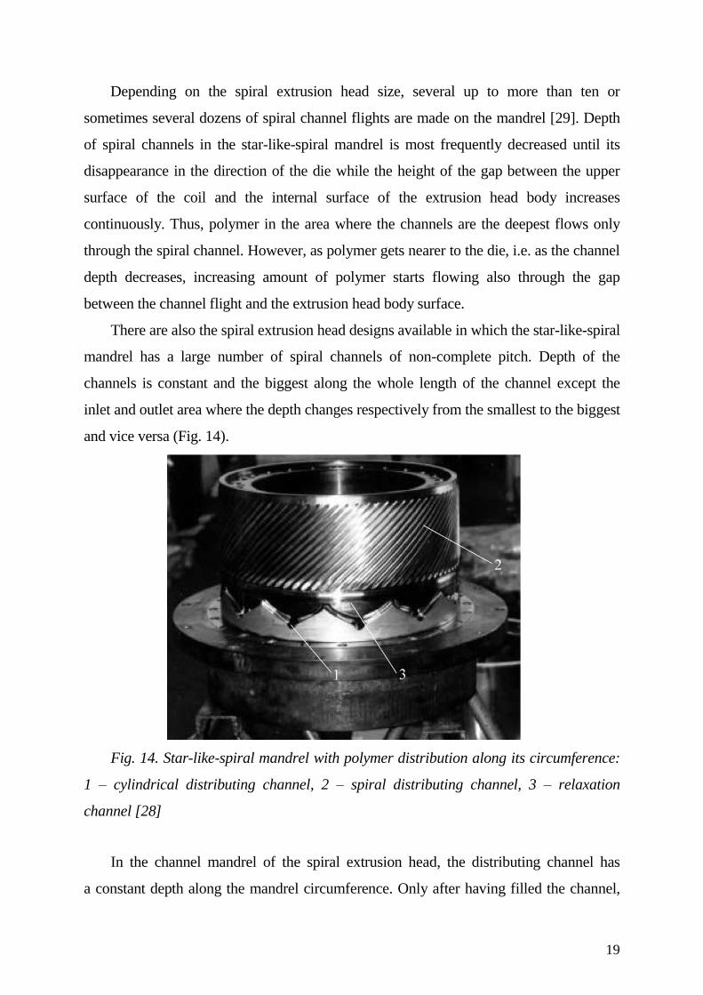
There are also the spiral extrusion head designs available in which the star-like-spiral
mandrel has a large number of spiral channels of non-complete pitch. Depth of the
channels is constant and the biggest along the whole length of the channel except the
inlet and outlet area where the depth changes respectively from the smallest to the biggest
and vice versa (Fig. 14).
Fig. 14. Star-like-spiral mandrel with polymer distribution along its circumference:
1 – cylindrical distributing channel, 2 – spiral distributing channel, 3 – relaxation
channel [28]
In the channel mandrel of the spiral extrusion head, the distributing channel has
a constant depth along the mandrel circumference. Only after having filled the channel,
20
polymer flows to helical distributing channels the depth of which is most frequently
constant as well.
Sometimes [44], instead of star-like-spiral mandrel with a star-like system of
distributing channels, the cylindrical-spiral mandrel is used in which polymer is supplied
to the spiral channels through the annular system of the distributing channel.
The use of channel mandrels causes that the stream of plasticized polymer created by
multiple overlapping of circumferential and longitudinal streams flows through the
extrusion head die. These streams are created as a result polymer distribution along the
circumference of the channel mandrel through the spiral channels of decreasing depth
that are made on the cylindrical surface of the mandrel and due to increasing height of the
gap between the upper surface of the flight and the internal surface of the extrusion head
body. Overlapping of component polymer streams that flow in various directions enables
a thorough mixing and unification of properties as well as a correct distribution of speed
and temperature of polymer being extruded. The advantage of the spiral extrusion head is
also the lack of mandrel fixing elements and polymer dividing elements which
completely eliminates the connection lines that are created when the component streams
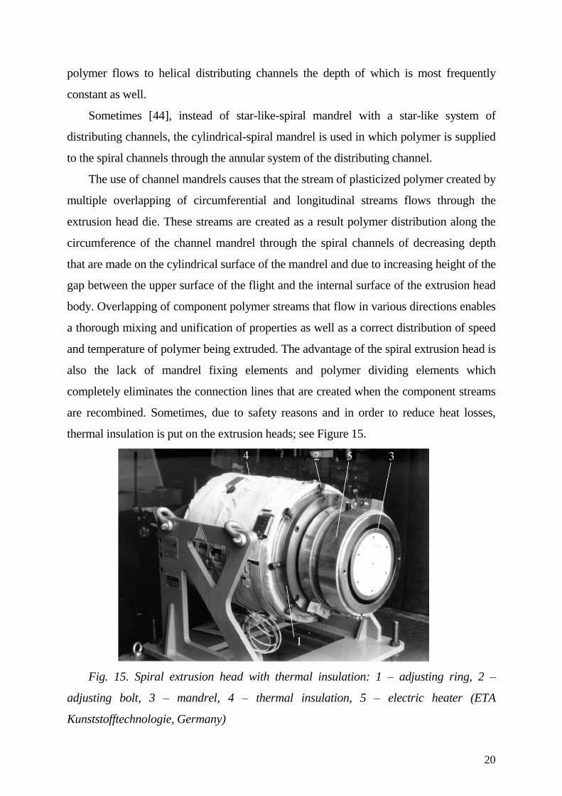
are recombined. Sometimes, due to safety reasons and in order to reduce heat losses,
thermal insulation is put on the extrusion heads; see Figure 15.
Fig. 15. Spiral extrusion head with thermal insulation: 1 – adjusting ring, 2 –
adjusting bolt, 3 – mandrel, 4 – thermal insulation, 5 – electric heater (ETA
Kunststofftechnologie, Germany)
21
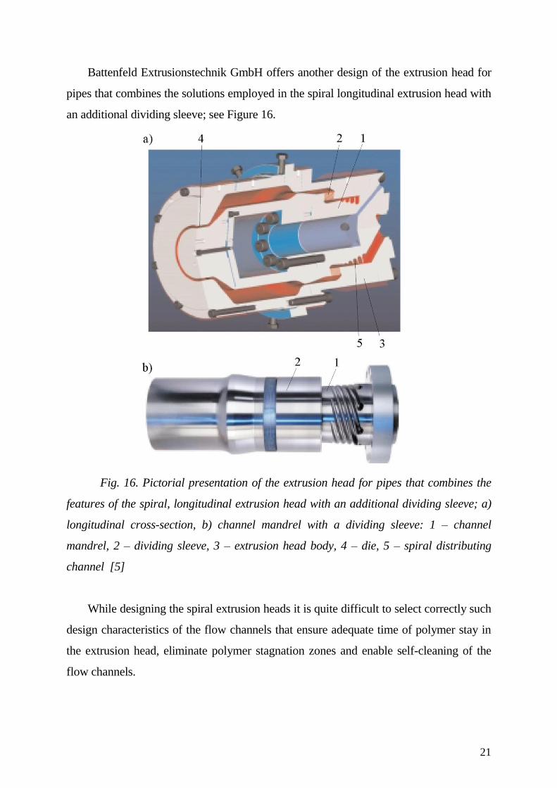
Battenfeld Extrusionstechnik GmbH offers another design of the extrusion head for
pipes that combines the solutions employed in the spiral longitudinal extrusion head with
an additional dividing sleeve; see Figure 16.
Fig. 16. Pictorial presentation of the extrusion head for pipes that combines the
features of the spiral, longitudinal extrusion head with an additional dividing sleeve; a)
longitudinal cross-section, b) channel mandrel with a dividing sleeve: 1 – channel
mandrel, 2 – dividing sleeve, 3 – extrusion head body, 4 – die, 5 – spiral distributing
channel [5]
While designing the spiral extrusion heads it is quite difficult to select correctly such
design characteristics of the flow channels that ensure adequate time of polymer stay in
the extrusion head, eliminate polymer stagnation zones and enable self-cleaning of the
flow channels.

22
2.2. Non-circular extrusion head
Profiles that have a cross-section other than circular one, open as well as closed
ones, are produced with the use of non-circular extrusion head. These extrusion heads
can be categorized into single-plate and multi-plate longitudinal extrusion heads while
the later ones can be distinguished by a step-like or a continuous change of the
distributing channel cross–section. While designing these extrusion heads special
attention is paid to swelling, the processing shrinkage phenomenon concerning the
polymer processed and ensuring possibly identical speed of polymer outflow from the die
and the polymer temperature in the cross-section of the profile.
Longitudinal single-plate extrusion head (Fig. 17) is relatively cheap and easy to
make, assemble and possibly correct the shape of the die cross-section.
Fig. 17. Diagram of the cross-section of the longitudinal single-plate extrusion
head: 1- mandrel, 2 – inlet channel, 3 – dividing channel, 4 – distributing channel, 5 –
mandrel torpedo, 6 – flat plate, 7 – extrusion head body, 8 - die
In principle, this type of extrusion head differs from the longitudinal extrusion head
for profiles of circular cross-section with regard to design of the shaping unit and
resulting design of the distributing channel. The shaping unit of the longitudinal single-
plate extrusion head consists of a single, flat plate of a thickness between more than and
several dozens millimetres in which a hole (or rarely holes) having a shape close to that
23
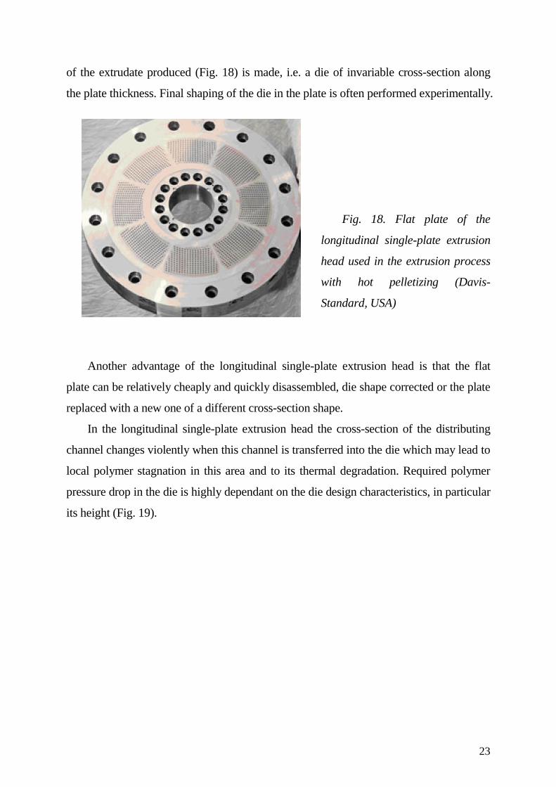
of the extrudate produced (Fig. 18) is made, i.e. a die of invariable cross-section along
the plate thickness. Final shaping of the die in the plate is often performed experimentally.
Fig. 18. Flat plate of the
longitudinal single-plate extrusion
head used in the extrusion process
with hot pelletizing (Davis-
Standard, USA)
Another advantage of the longitudinal single-plate extrusion head is that the flat
plate can be relatively cheaply and quickly disassembled, die shape corrected or the plate
replaced with a new one of a different cross-section shape.
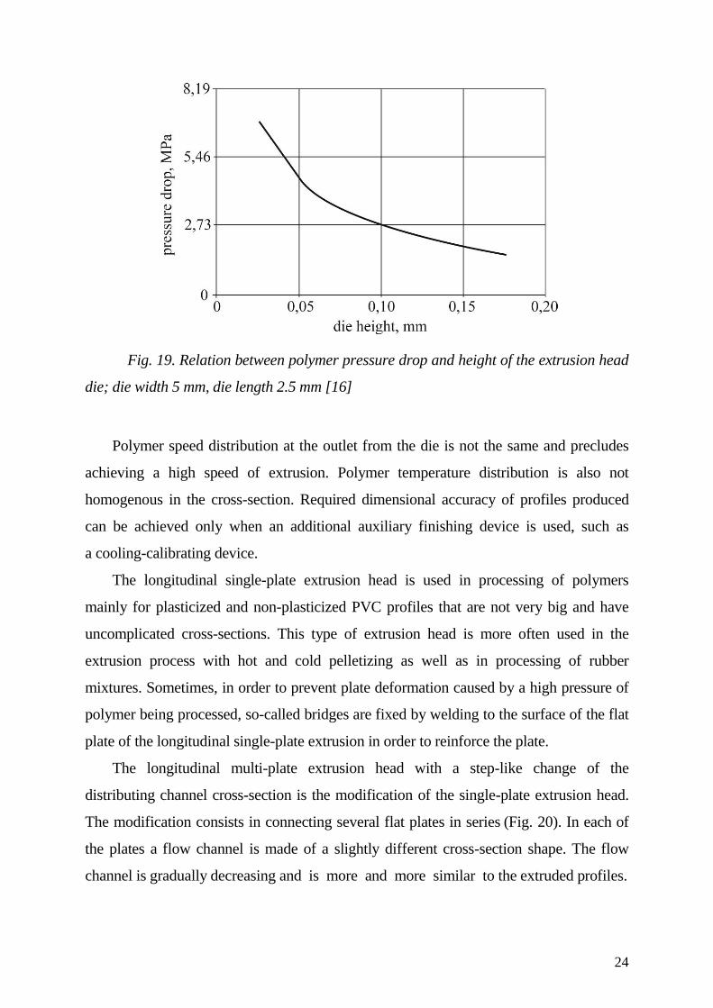
In the longitudinal single-plate extrusion head the cross-section of the distributing
channel changes violently when this channel is transferred into the die which may lead to
local polymer stagnation in this area and to its thermal degradation. Required polymer
pressure drop in the die is highly dependant on the die design characteristics, in particular
its height (Fig. 19).
24
Fig. 19. Relation between polymer pressure drop and height of the extrusion head
die; die width 5 mm, die length 2.5 mm [16]
Polymer speed distribution at the outlet from the die is not the same and precludes
achieving a high speed of extrusion. Polymer temperature distribution is also not
homogenous in the cross-section. Required dimensional accuracy of profiles produced
can be achieved only when an additional auxiliary finishing device is used, such as
a cooling-calibrating device.
The longitudinal single-plate extrusion head is used in processing of polymers
mainly for plasticized and non-plasticized PVC profiles that are not very big and have
uncomplicated cross-sections. This type of extrusion head is more often used in the
extrusion process with hot and cold pelletizing as well as in processing of rubber
mixtures. Sometimes, in order to prevent plate deformation caused by a high pressure of
polymer being processed, so-called bridges are fixed by welding to the surface of the flat
plate of the longitudinal single-plate extrusion in order to reinforce the plate.
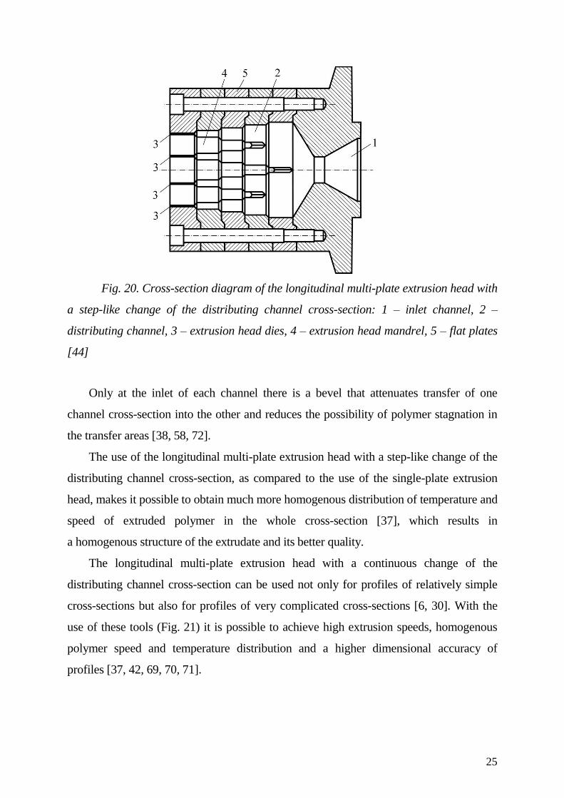
The longitudinal multi-plate extrusion head with a step-like change of the
distributing channel cross-section is the modification of the single-plate extrusion head.
The modification consists in connecting several flat plates in series (Fig. 20). In each of
the plates a flow channel is made of a slightly different cross-section shape. The flow
channel is gradually decreasing and is more and more similar to the extruded profiles.
25
Fig. 20. Cross-section diagram of the longitudinal multi-plate extrusion head with
a step-like change of the distributing channel cross-section: 1 – inlet channel, 2 –
distributing channel, 3 – extrusion head dies, 4 – extrusion head mandrel, 5 – flat plates
[44]
Only at the inlet of each channel there is a bevel that attenuates transfer of one
channel cross-section into the other and reduces the possibility of polymer stagnation in
the transfer areas [38, 58, 72].
The use of the longitudinal multi-plate extrusion head with a step-like change of the
distributing channel cross-section, as compared to the use of the single-plate extrusion
head, makes it possible to obtain much more homogenous distribution of temperature and
speed of extruded polymer in the whole cross-section [37], which results in
a homogenous structure of the extrudate and its better quality.
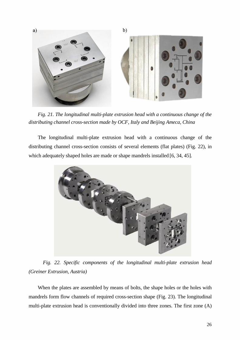
The longitudinal multi-plate extrusion head with a continuous change of the
distributing channel cross-section can be used not only for profiles of relatively simple
cross-sections but also for profiles of very complicated cross-sections [6, 30]. With the
use of these tools (Fig. 21) it is possible to achieve high extrusion speeds, homogenous
polymer speed and temperature distribution and a higher dimensional accuracy of
profiles [37, 42, 69, 70, 71].
26
Fig. 21. The longitudinal multi-plate extrusion head with a continuous change of the
distributing channel cross-section made by OCF, Italy and Beijing Ameca, China
The longitudinal multi-plate extrusion head with a continuous change of the
distributing channel cross-section consists of several elements (flat plates) (Fig. 22), in
which adequately shaped holes are made or shape mandrels installed [6, 34, 45].
Fig. 22. Specific components of the longitudinal multi-plate extrusion head
(Greiner Extrusion, Austria)
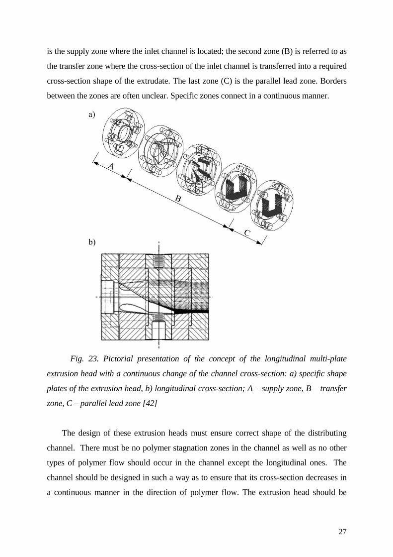
When the plates are assembled by means of bolts, the shape holes or the holes with
mandrels form flow channels of required cross-section shape (Fig. 23). The longitudinal
multi-plate extrusion head is conventionally divided into three zones. The first zone (A)
27
is the supply zone where the inlet channel is located; the second zone (B) is referred to as
the transfer zone where the cross-section of the inlet channel is transferred into a required
cross-section shape of the extrudate. The last zone (C) is the parallel lead zone. Borders
between the zones are often unclear. Specific zones connect in a continuous manner.
Fig. 23. Pictorial presentation of the concept of the longitudinal multi-plate
extrusion head with a continuous change of the channel cross-section: a) specific shape
plates of the extrusion head, b) longitudinal cross-section; A – supply zone, B – transfer
zone, C – parallel lead zone [42]
The design of these extrusion heads must ensure correct shape of the distributing
channel. There must be no polymer stagnation zones in the channel as well as no other
types of polymer flow should occur in the channel except the longitudinal ones. The
channel should be designed in such a way as to ensure that its cross-section decreases in
a continuous manner in the direction of polymer flow. The extrusion head should be
28
made in the simplest possible way due to the necessity of possible corrections of the flow
channel shape and its cleaning. Consequently, designing these extrusion heads is not
simple. In order to facilitate, accelerate and limit the corrections of the flow channel
shape in the longitudinal multi-plate extrusion head with a step-like or continuous change
of the distributing channel cross-section shape, various computer programs are used [37,
68, 80] that aid the design process and simulate polymer flow in such a channel.
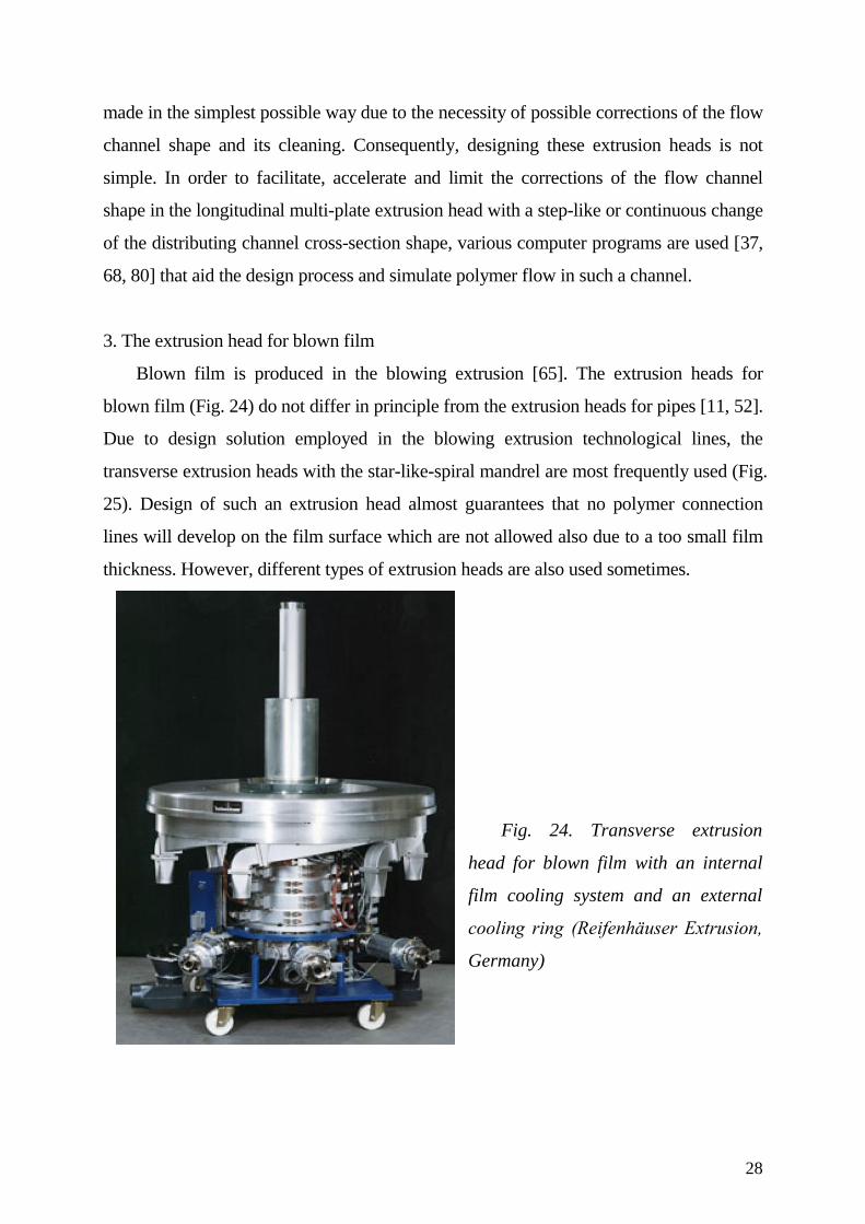
3. The extrusion head for blown film
Blown film is produced in the blowing extrusion [65]. The extrusion heads for
blown film (Fig. 24) do not differ in principle from the extrusion heads for pipes [11, 52].
Due to design solution employed in the blowing extrusion technological lines, the
transverse extrusion heads with the star-like-spiral mandrel are most frequently used (Fig.
25). Design of such an extrusion head almost guarantees that no polymer connection
lines will develop on the film surface which are not allowed also due to a too small film
thickness. However, different types of extrusion heads are also used sometimes.
Fig. 24. Transverse extrusion
head for blown film with an internal
film cooling system and an external
cooling ring (Reifenhäuser Extrusion,
Germany)
29
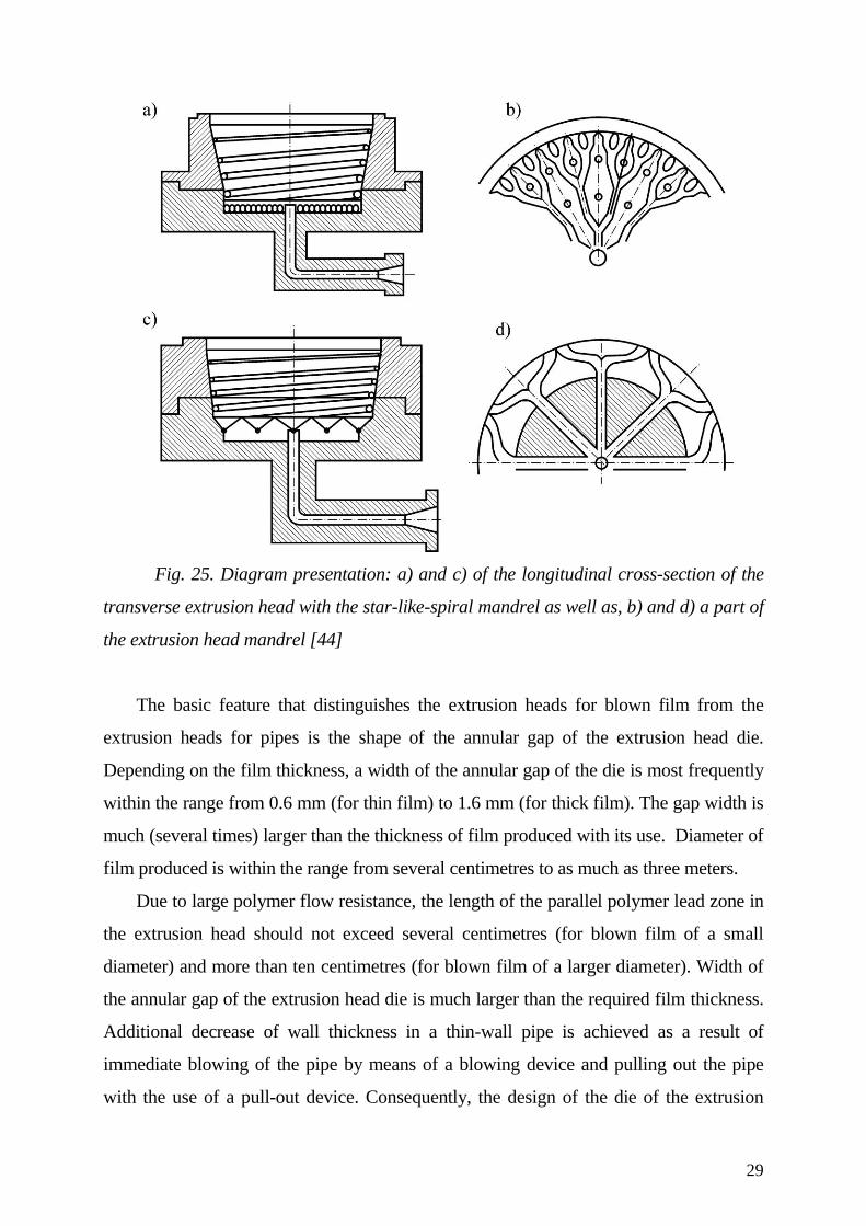
Fig. 25. Diagram presentation: a) and c) of the longitudinal cross-section of the
transverse extrusion head with the star-like-spiral mandrel as well as, b) and d) a part of
the extrusion head mandrel [44]
The basic feature that distinguishes the extrusion heads for blown film from the
extrusion heads for pipes is the shape of the annular gap of the extrusion head die.
Depending on the film thickness, a width of the annular gap of the die is most frequently
within the range from 0.6 mm (for thin film) to 1.6 mm (for thick film). The gap width is
much (several times) larger than the thickness of film produced with its use. Diameter of
film produced is within the range from several centimetres to as much as three meters.
Due to large polymer flow resistance, the length of the parallel polymer lead zone in
the extrusion head should not exceed several centimetres (for blown film of a small
diameter) and more than ten centimetres (for blown film of a larger diameter). Width of
the annular gap of the extrusion head die is much larger than the required film thickness.
Additional decrease of wall thickness in a thin-wall pipe is achieved as a result of
immediate blowing of the pipe by means of a blowing device and pulling out the pipe
with the use of a pull-out device. Consequently, the design of the die of the extrusion
30
head for blown film should take into account the degree of film blowing that is
determined as the relation between the blown film diameter and the die opening diameter.
It is also necessary to consider the degree of film stretching that is defined as the relation
between the film collecting speed and the speed at which the film leaves the extrusion
head die.
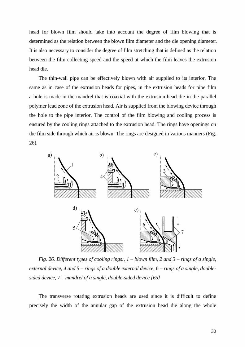
The thin-wall pipe can be effectively blown with air supplied to its interior. The
same as in case of the extrusion heads for pipes, in the extrusion heads for pipe film
a hole is made in the mandrel that is coaxial with the extrusion head die in the parallel
polymer lead zone of the extrusion head. Air is supplied from the blowing device through
the hole to the pipe interior. The control of the film blowing and cooling process is
ensured by the cooling rings attached to the extrusion head. The rings have openings on
the film side through which air is blown. The rings are designed in various manners (Fig.
26).
Fig. 26. Different types of cooling rings:, 1 – blown film, 2 and 3 – rings of a single,
external device, 4 and 5 – rings of a double external device, 6 – rings of a single, double-
sided device, 7 – mandrel of a single, double-sided device [65]
The transverse rotating extrusion heads are used since it is difficult to define
precisely the width of the annular gap of the extrusion head die along the whole
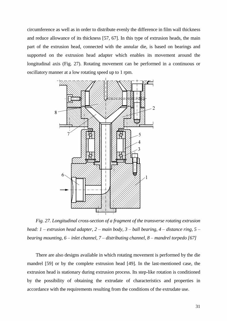
31
circumference as well as in order to distribute evenly the difference in film wall thickness
and reduce allowance of its thickness [57, 67]. In this type of extrusion heads, the main
part of the extrusion head, connected with the annular die, is based on bearings and
supported on the extrusion head adapter which enables its movement around the
longitudinal axis (Fig. 27). Rotating movement can be performed in a continuous or
oscillatory manner at a low rotating speed up to 1 rpm.
Fig. 27. Longitudinal cross-section of a fragment of the transverse rotating extrusion
head: 1 – extrusion head adapter, 2 – main body, 3 – ball bearing, 4 – distance ring, 5 –
bearing mounting, 6 – inlet channel, 7 – distributing channel, 8 – mandrel torpedo [67]
There are also designs available in which rotating movement is performed by the die
mandrel [59] or by the complete extrusion head [49]. In the last-mentioned case, the
extrusion head is stationary during extrusion process. Its step-like rotation is conditioned
by the possibility of obtaining the extrudate of characteristics and properties in
accordance with the requirements resulting from the conditions of the extrudate use.
32
4. Extrusion head for flat sheet and film
One of the criteria distinguishing the flat sheet and film is their thickness and
susceptibility of extruded polymer to coiling without permanent deformations and defects.
10 years ago the thickness was still conventionally assumed [44, 52] to be within the
range from 0.5 to 0.7 mm. However, the progress in polymer processing as well as
development of machines and tools enabled obtaining more and more thick film and
sheet of lower thickness. At present, it is possible to produce a several millimetre thick
flat film for further processing, for example by thermoforming [66], while the sheet may
be even several decimal parts of millimetre thin. Thus, the susceptibility of extruded
polymer to coiling without permanent deformations and defects has become the main
criterion.
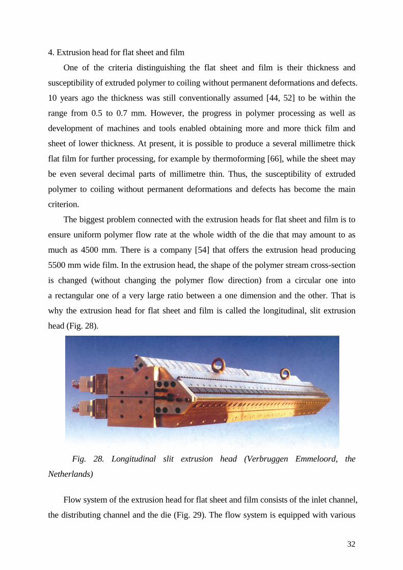
The biggest problem connected with the extrusion heads for flat sheet and film is to
ensure uniform polymer flow rate at the whole width of the die that may amount to as
much as 4500 mm. There is a company [54] that offers the extrusion head producing
5500 mm wide film. In the extrusion head, the shape of the polymer stream cross-section
is changed (without changing the polymer flow direction) from a circular one into
a rectangular one of a very large ratio between a one dimension and the other. That is
why the extrusion head for flat sheet and film is called the longitudinal, slit extrusion
head (Fig. 28).
Fig. 28. Longitudinal slit extrusion head (Verbruggen Emmeloord, the
Netherlands)
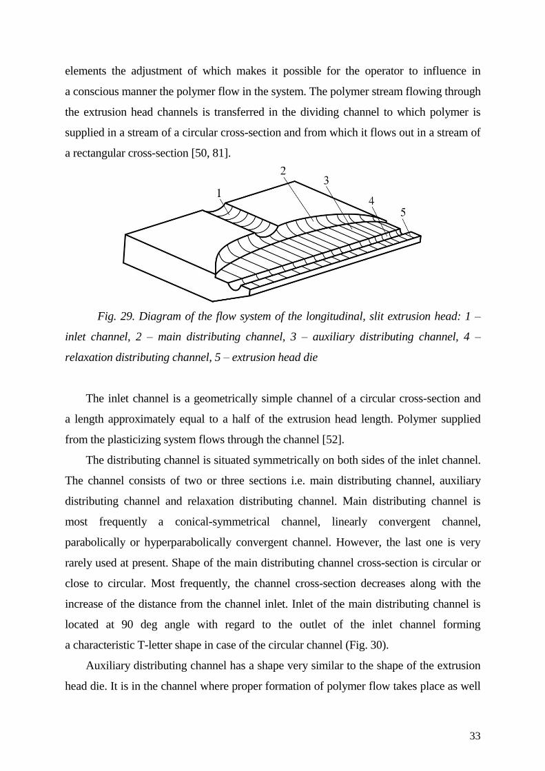
Flow system of the extrusion head for flat sheet and film consists of the inlet channel,
the distributing channel and the die (Fig. 29). The flow system is equipped with various
33
elements the adjustment of which makes it possible for the operator to influence in
a conscious manner the polymer flow in the system. The polymer stream flowing through
the extrusion head channels is transferred in the dividing channel to which polymer is
supplied in a stream of a circular cross-section and from which it flows out in a stream of
a rectangular cross-section [50, 81].
Fig. 29. Diagram of the flow system of the longitudinal, slit extrusion head: 1 –
inlet channel, 2 – main distributing channel, 3 – auxiliary distributing channel, 4 –
relaxation distributing channel, 5 – extrusion head die
The inlet channel is a geometrically simple channel of a circular cross-section and
a length approximately equal to a half of the extrusion head length. Polymer supplied
from the plasticizing system flows through the channel [52].
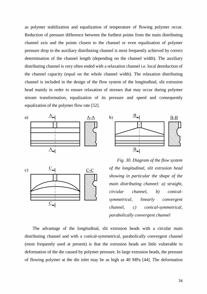
The distributing channel is situated symmetrically on both sides of the inlet channel.
The channel consists of two or three sections i.e. main distributing channel, auxiliary
distributing channel and relaxation distributing channel. Main distributing channel is
most frequently a conical-symmetrical channel, linearly convergent channel,
parabolically or hyperparabolically convergent channel. However, the last one is very
rarely used at present. Shape of the main distributing channel cross-section is circular or
close to circular. Most frequently, the channel cross-section decreases along with the
increase of the distance from the channel inlet. Inlet of the main distributing channel is
located at 90 deg angle with regard to the outlet of the inlet channel forming
a characteristic T-letter shape in case of the circular channel (Fig. 30).
Auxiliary distributing channel has a shape very similar to the shape of the extrusion
head die. It is in the channel where proper formation of polymer flow takes place as well
34
as polymer stabilization and equalization of temperature of flowing polymer occur.
Reduction of pressure difference between the furthest points from the main distributing
channel axis and the points closest to the channel or even equalization of polymer
pressure drop in the auxiliary distributing channel is most frequently achieved by correct
determination of the channel length (depending on the channel width). The auxiliary
distributing channel is very often ended with a relaxation channel i.e. local dereduction of
the channel capacity (equal on the whole channel width). The relaxation distributing
channel is included in the design of the flow system of the longitudinal, slit extrusion
head mainly in order to ensure relaxation of stresses that may occur during polymer
stream transformation, equalization of its pressure and speed and consequently
equalization of the polymer flow rate [52].
Fig. 30. Diagram of the flow system
of the longitudinal, slit extrusion head
showing in particular the shape of the
main distributing channel: a) straight,
circular channel, b) conical-
symmetrical, linearly convergent
channel, c) conical-symmetrical,
parabolically convergent channel
The advantage of the longitudinal, slit extrusion heads with a circular main
distributing channel and with a conical-symmetrical, parabolically convergent channel
(most frequently used at present) is that the extrusion heads are little vulnerable to
deformation of the die caused by polymer pressure. In large extrusion heads, the pressure
of flowing polymer at the die inlet may be as high as 40 MPa [44]. The deformation
35
consists in shape changing (the shape change is the largest in the axis of the longitudinal
cross-section of the extrusion head die) in such a way that the plate or film produced has
the biggest thickness in the longitudinal axis. Total polymer pressure drop during
polymer flow through the flow system of the longitudinal, slit extrusion head may be up
to 20 MPa [44]. The extrusion heads with a conical-symmetrical, linearly convergent
main distributing channel are characterized by a considerably better polymer distribution
than the polymer distribution offered by the extrusion heads with a circular distributing
channel. However, the cost of making the extrusion heads with a circular distributing
channel is the lowest and that is why they are still used.
The flow system of the longitudinal, slit extrusion head is ended with a die that
offers the possibility of polymer flow rate adjustment on its whole width with the use of
movable die elements. Changing the position of these elements also corrects possible
deformation of the die caused by polymer flow. Such movable elements that influence
the polymer stream are located also before the die, most frequently in the auxiliary
distributing channel [26, 52, 82]. Consequently, a more homogenous polymer flow and
smaller die deformation are achieved.
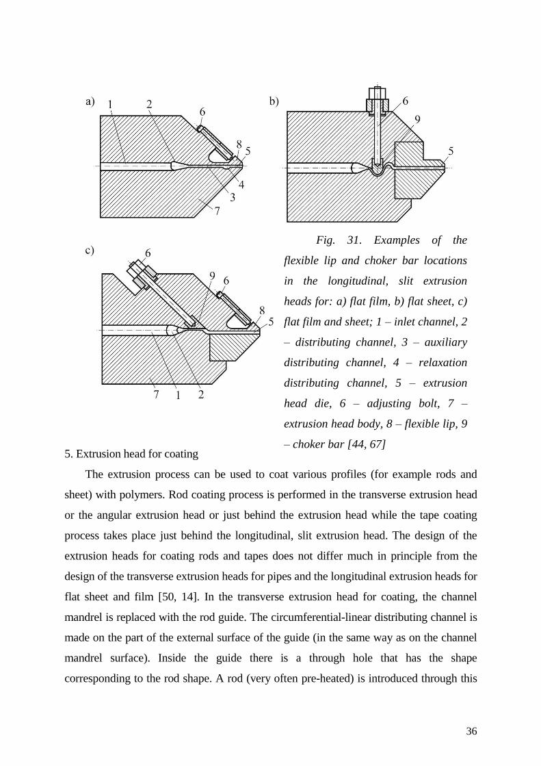
The elements that have adequately shaped surfaces are used to adjust the polymer
flow. These may be choker bars or flexible lips (Fig. 31). They enable continuous change
of the flow channel depth or the die height. The choker bars are most frequently used in
the extrusion heads for sheet [1]. Polymer flow adjustment by continuous changing of the
die height with the use flexible lip of the die is more often used in the extrusion heads for
flat film than in the extrusion heads for sheet. These elements can be connected with the
system of piezoelectric sensors that react to pressure of polymer in the distributing
channels and change the height of the extrusion head die. Extruded film is very often
subjected to further processing in the calendaring process.
36
5. Extrusion head for coating
The extrusion process can be used to coat various profiles (for example rods and
sheet) with polymers. Rod coating process is performed in the transverse extrusion head
or the angular extrusion head or just behind the extrusion head while the tape coating
process takes place just behind the longitudinal, slit extrusion head. The design of the
extrusion heads for coating rods and tapes does not differ much in principle from the
design of the transverse extrusion heads for pipes and the longitudinal extrusion heads for
flat sheet and film [50, 14]. In the transverse extrusion head for coating, the channel
mandrel is replaced with the rod guide. The circumferential-linear distributing channel is
made on the part of the external surface of the guide (in the same way as on the channel
mandrel surface). Inside the guide there is a through hole that has the shape
corresponding to the rod shape. A rod (very often pre-heated) is introduced through this
Fig. 31. Examples of the
flexible lip and choker bar locations
in the longitudinal, slit extrusion
heads for: a) flat film, b) flat sheet, c)
flat film and sheet; 1 – inlet channel, 2
– distributing channel, 3 – auxiliary
distributing channel, 4 – relaxation
distributing channel, 5 – extrusion
head die, 6 – adjusting bolt, 7 –
extrusion head body, 8 – flexible lip, 9
– choker bar [44, 67]
37
hole. The rod is coated with polymer in the extrusion head die or just behind it. The basic
problem is to design correctly the flow system of the extrusion head (first of all to design
correctly the circumferential-linear channel located on the cylindrical or conical surface
of the guide in the transverse extrusion head or the angular extrusion head and the main
distributing channel in the slit extrusion head) in such a way as to achieve a uniform
polymer extrusion speed.
Rod coating process that takes place in the extrusion head is called the pressure
coating and is performed under influence of polymer pressure in the die. Rod coating
process that takes place just behind the extrusion head is conventionally referred to as the
vacuum coating since it is performed under influence of atmospheric pressure which is
higher than the pressure created in the area between the rod and polymer extruded [32, 65,
67].
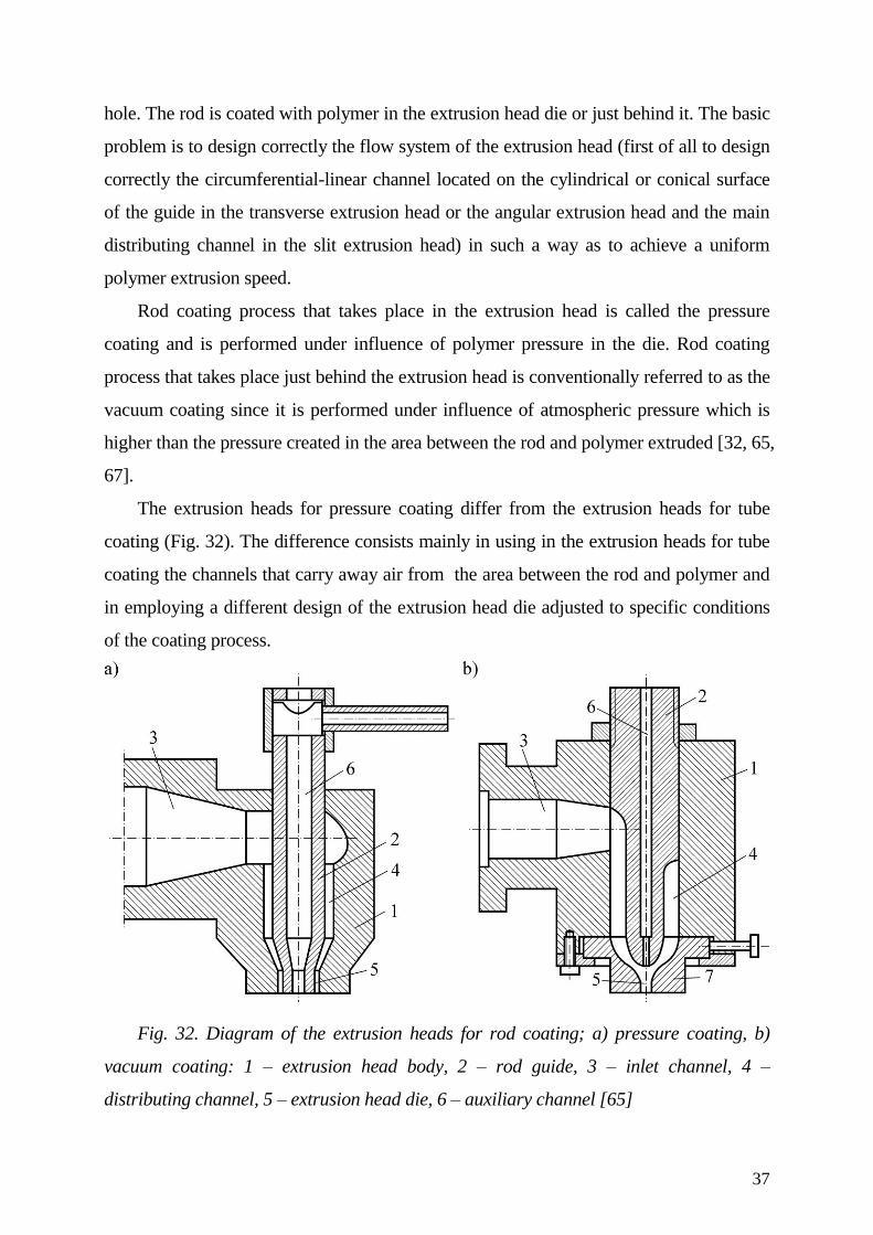
The extrusion heads for pressure coating differ from the extrusion heads for tube
coating (Fig. 32). The difference consists mainly in using in the extrusion heads for tube
coating the channels that carry away air from the area between the rod and polymer and
in employing a different design of the extrusion head die adjusted to specific conditions
of the coating process.
Fig. 32. Diagram of the extrusion heads for rod coating; a) pressure coating, b)
vacuum coating: 1 – extrusion head body, 2 – rod guide, 3 – inlet channel, 4 –
distributing channel, 5 – extrusion head die, 6 – auxiliary channel [65]
38
The advantage of the extrusion heads for tube coating is that they offer a more
possibilities of coating rods of various cross-section shapes. Their disadvantage is the
necessity of making the vacuum channels and using the system for reducing pressure just
behind the extrusion head die. The advantage of the extrusion heads for pressure coating
is that they offer the possibility of obtaining very thin coatings (even as thin as 0.01 mm).
Their disadvantage is the difficulty in maintaining uniform coating thickness on the
whole rod circumference and limitation of the rod cross-section shape to a circular or
close the circular [65, 73].
The angle between the extruder axis and the main axis of the extrusion head for
coating may be 45, 60 or 90 deg, but most frequently this angle is 90 deg. The smaller the
angle, the bigger the movement direction changes the polymer is subjected to before it
starts surrounding the rod concentrically. The extrusion heads of smaller angles enable
reduction of distance between the technological lines of the coating extrusion process and
consequently, better utilization of the production building area.
Due to a high speed of coating of the small diameter rods (even up to several
kilometres per minute) and dimensions of the gap between the rod and the die body (the
value of which in case of the pressure extrusion is lower than 0.05 mm) the ending of the
die body is often made of materials resistant to abrasive wear, for example of diamond,
aluminium silicate or a special alloy of metals. Geometric features of the die affect to
a high degree the allowable coating speed as well as the quality of a coat obtained.
Smaller convergence and a longer parallel polymer lead zone in the extrusion head have
influence on a better surface quality. The length of the parallel polymer lead zone (die)
should be within the range from 0.2 to 2 diameters of the circular shape in case of PVC
coating and within the range from 2 to 5 diameters in case of PE coating.
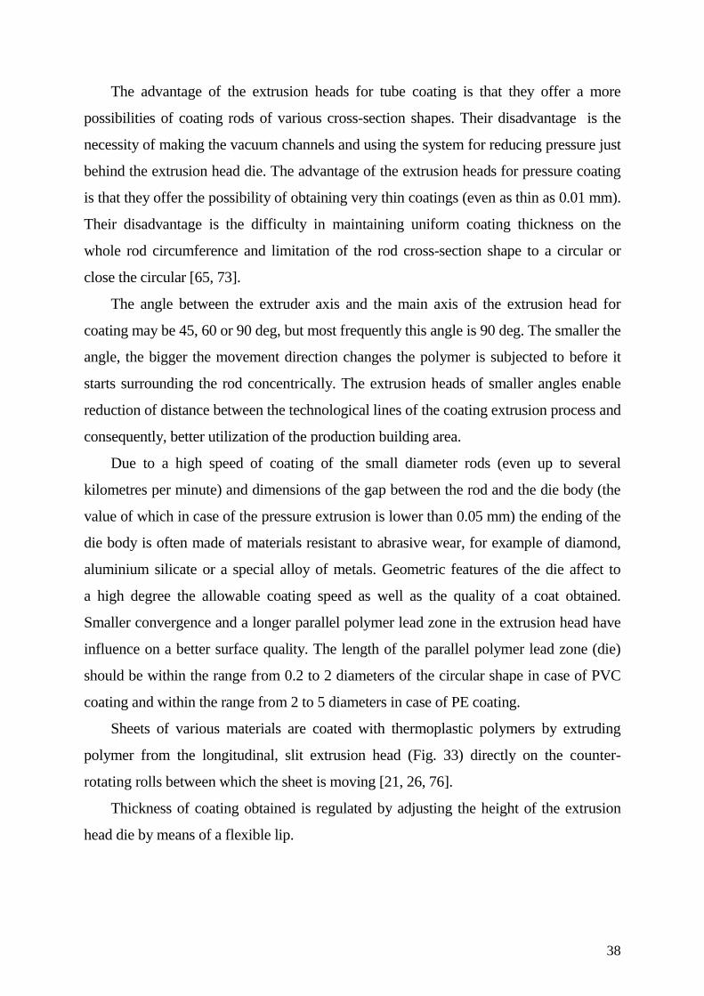
Sheets of various materials are coated with thermoplastic polymers by extruding
polymer from the longitudinal, slit extrusion head (Fig. 33) directly on the counter-
rotating rolls between which the sheet is moving [21, 26, 76].
Thickness of coating obtained is regulated by adjusting the height of the extrusion
head die by means of a flexible lip.
39
Fig. 33. The
longitudinal, slit extrusion
head for sheet coating: 1 –
die body, 2 – extrusion head
body, 3 – flexible lip, 4 –
adjusting bolts of the
flexible lip (Extrusion Dies
Industries, USA)
6. Extrusion head for pelletizing
The extrusion process with polymer pelletizing is performed as cold or hot process
[15, 65, 67].
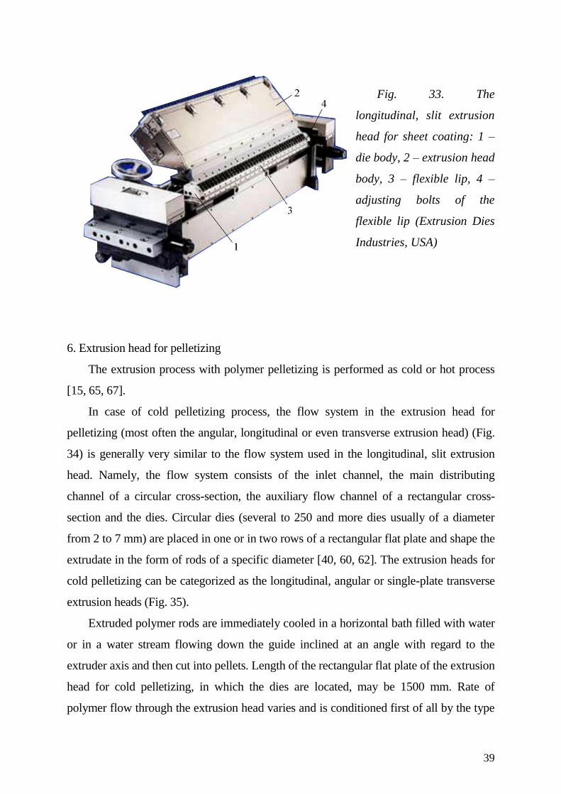
In case of cold pelletizing process, the flow system in the extrusion head for
pelletizing (most often the angular, longitudinal or even transverse extrusion head) (Fig.
34) is generally very similar to the flow system used in the longitudinal, slit extrusion
head. Namely, the flow system consists of the inlet channel, the main distributing
channel of a circular cross-section, the auxiliary flow channel of a rectangular cross-
section and the dies. Circular dies (several to 250 and more dies usually of a diameter
from 2 to 7 mm) are placed in one or in two rows of a rectangular flat plate and shape the
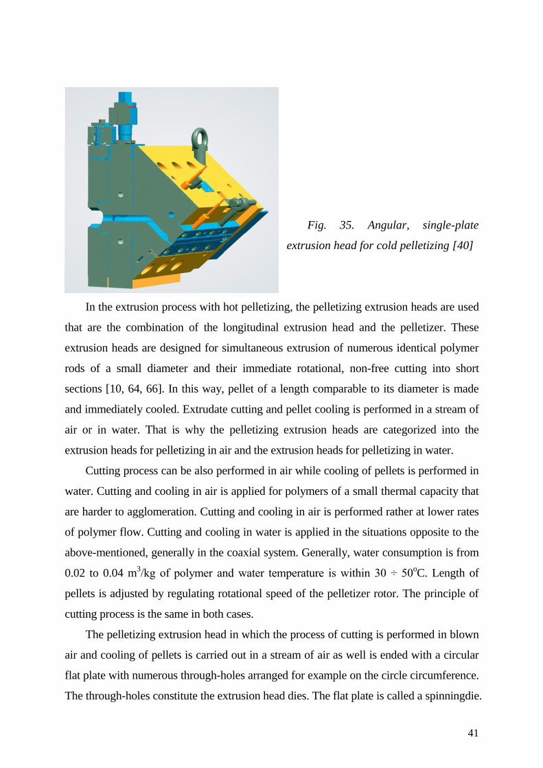
extrudate in the form of rods of a specific diameter [40, 60, 62]. The extrusion heads for
cold pelletizing can be categorized as the longitudinal, angular or single-plate transverse
extrusion heads (Fig. 35).
Extruded polymer rods are immediately cooled in a horizontal bath filled with water
or in a water stream flowing down the guide inclined at an angle with regard to the
extruder axis and then cut into pellets. Length of the rectangular flat plate of the extrusion
head for cold pelletizing, in which the dies are located, may be 1500 mm. Rate of
polymer flow through the extrusion head varies and is conditioned first of all by the type
40
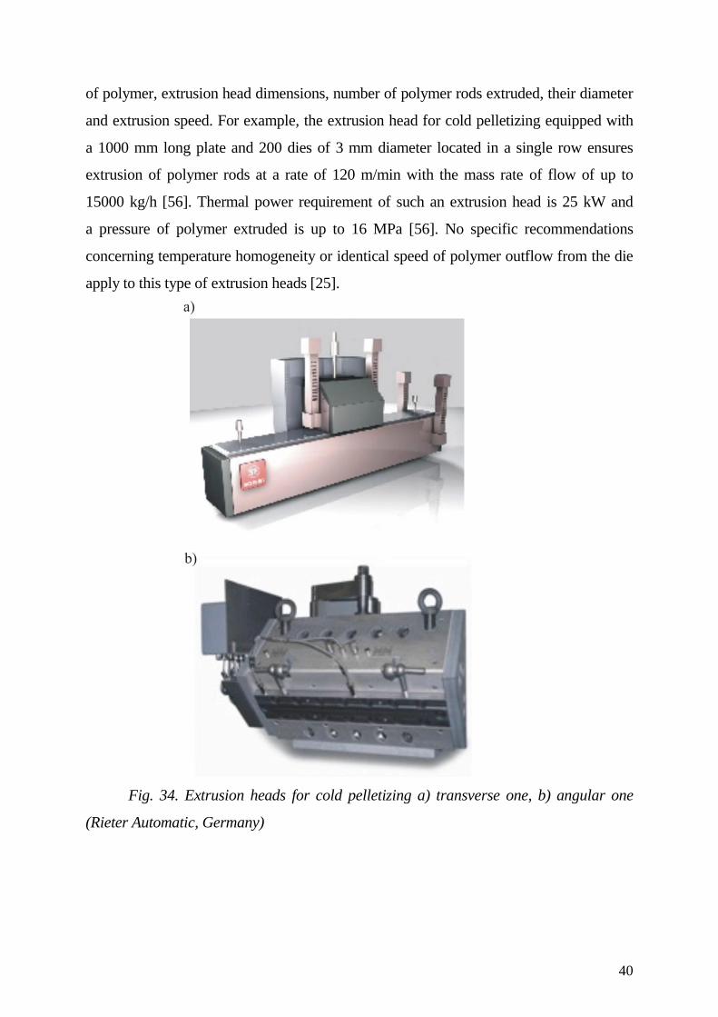
of polymer, extrusion head dimensions, number of polymer rods extruded, their diameter
and extrusion speed. For example, the extrusion head for cold pelletizing equipped with
a 1000 mm long plate and 200 dies of 3 mm diameter located in a single row ensures
extrusion of polymer rods at a rate of 120 m/min with the mass rate of flow of up to
15000 kg/h [56]. Thermal power requirement of such an extrusion head is 25 kW and
a pressure of polymer extruded is up to 16 MPa [56]. No specific recommendations
concerning temperature homogeneity or identical speed of polymer outflow from the die
apply to this type of extrusion heads [25].
Fig. 34. Extrusion heads for cold pelletizing a) transverse one, b) angular one
(Rieter Automatic, Germany)
41
Fig. 35. Angular, single-plate
extrusion head for cold pelletizing [40]
In the extrusion process with hot pelletizing, the pelletizing extrusion heads are used
that are the combination of the longitudinal extrusion head and the pelletizer. These
extrusion heads are designed for simultaneous extrusion of numerous identical polymer
rods of a small diameter and their immediate rotational, non-free cutting into short
sections [10, 64, 66]. In this way, pellet of a length comparable to its diameter is made
and immediately cooled. Extrudate cutting and pellet cooling is performed in a stream of
air or in water. That is why the pelletizing extrusion heads are categorized into the
extrusion heads for pelletizing in air and the extrusion heads for pelletizing in water.
Cutting process can be also performed in air while cooling of pellets is performed in
water. Cutting and cooling in air is applied for polymers of a small thermal capacity that
are harder to agglomeration. Cutting and cooling in air is performed rather at lower rates
of polymer flow. Cutting and cooling in water is applied in the situations opposite to the
above-mentioned, generally in the coaxial system. Generally, water consumption is from
0.02 to 0.04 m3/kg of polymer and water temperature is within 30 ÷ 50
oC. Length of
pellets is adjusted by regulating rotational speed of the pelletizer rotor. The principle of
cutting process is the same in both cases.
The pelletizing extrusion head in which the process of cutting is performed in blown
air and cooling of pellets is carried out in a stream of air as well is ended with a circular
flat plate with numerous through-holes arranged for example on the circle circumference.
The through-holes constitute the extrusion head dies. The flat plate is called a spinningdie.
42
After cutting, pellets are blown from the knives. They fall down and are transported
pneumatically to the cooling device. Temperature of polymer during the cutting process
is almost equal to the extrusion temperature. That is why it may happen that pellets
adhere to the knives and connect with other pellets which disturb the pelletizing process.
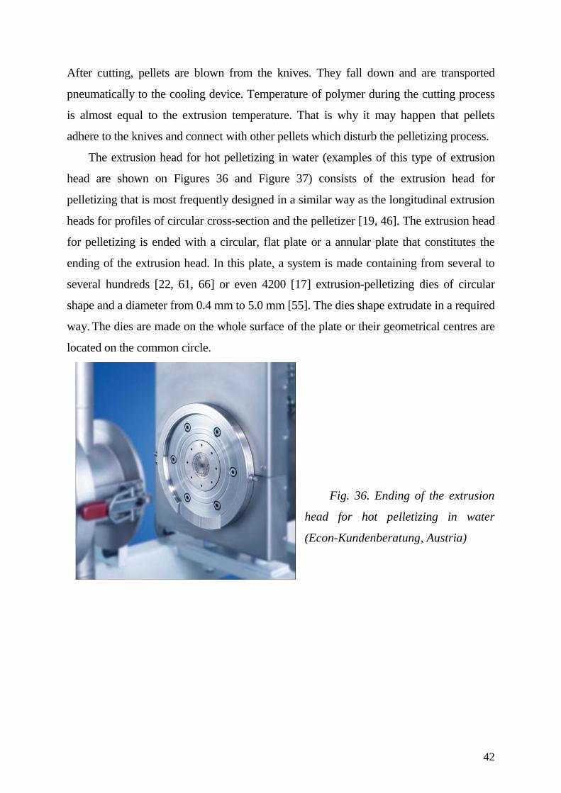
The extrusion head for hot pelletizing in water (examples of this type of extrusion
head are shown on Figures 36 and Figure 37) consists of the extrusion head for
pelletizing that is most frequently designed in a similar way as the longitudinal extrusion
heads for profiles of circular cross-section and the pelletizer [19, 46]. The extrusion head
for pelletizing is ended with a circular, flat plate or a annular plate that constitutes the
ending of the extrusion head. In this plate, a system is made containing from several to
several hundreds [22, 61, 66] or even 4200 [17] extrusion-pelletizing dies of circular
shape and a diameter from 0.4 mm to 5.0 mm [55]. The dies shape extrudate in a required
way. The dies are made on the whole surface of the plate or their geometrical centres are
located on the common circle.
Fig. 36. Ending of the extrusion
head for hot pelletizing in water
(Econ-Kundenberatung, Austria)
43
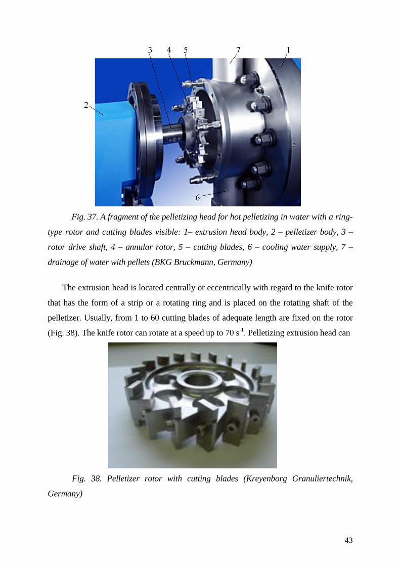
Fig. 37. A fragment of the pelletizing head for hot pelletizing in water with a ring-
type rotor and cutting blades visible: 1– extrusion head body, 2 – pelletizer body, 3 –
rotor drive shaft, 4 – annular rotor, 5 – cutting blades, 6 – cooling water supply, 7 –
drainage of water with pellets (BKG Bruckmann, Germany)
The extrusion head is located centrally or eccentrically with regard to the knife rotor
that has the form of a strip or a rotating ring and is placed on the rotating shaft of the
pelletizer. Usually, from 1 to 60 cutting blades of adequate length are fixed on the rotor
(Fig. 38). The knife rotor can rotate at a speed up to 70 s-1
. Pelletizing extrusion head can
Fig. 38. Pelletizer rotor with cutting blades (Kreyenborg Granuliertechnik,
Germany)
44
can cooperate with the extruders that are characterized by a mass rate of flow even up to
52000 kg/h. Water is supplied to the cutting chamber directly through the hole in the
rotor shaft and then to specific arms of the rotating strip. Water can be also supplied to
the cutting chamber directly at (/2) rad with regard to the extruder axis.
Water pressure is sometimes so high that cutting of polymer is performed by means
of a water stream and no cutting blades are used in such a case. Pellets obtained by
cutting are washed away to the annular housing. Then, the pellets and water leave the
cutting chamber through the outlet hole. The extruders with the extrusion head for hot
pelletizing in water and cutting by means of a water stream operate at even so high
polymer flow rate as 75.000 kg/h. Water demand for such a polymer flow rate is 120
m3/h [5].
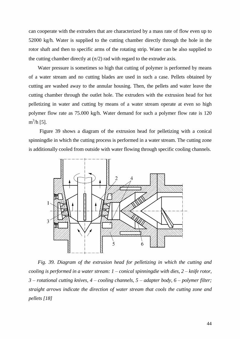
Figure 39 shows a diagram of the extrusion head for pelletizing with a conical
spinningdie in which the cutting process is performed in a water stream. The cutting zone
is additionally cooled from outside with water flowing through specific cooling channels.
Fig. 39. Diagram of the extrusion head for pelletizing in which the cutting and
cooling is performed in a water stream: 1 – conical spinningdie with dies, 2 – knife rotor,
3 – rotational cutting knives, 4 – cooling channels, 5 – adapter body, 6 – polymer filter;
straight arrows indicate the direction of water stream that cools the cutting zone and
pellets [18]
45
Such a solution deteriorates watt-hour efficiency of the complete process. Also,
additional activities are required after pelletizing in order to separate water from
pellets. Pellets are often subjected to drying.
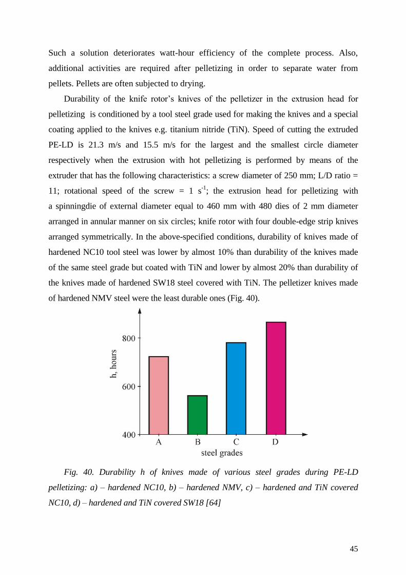
Durability of the knife rotor’s knives of the pelletizer in the extrusion head for
pelletizing is conditioned by a tool steel grade used for making the knives and a special
coating applied to the knives e.g. titanium nitride (TiN). Speed of cutting the extruded
PE-LD is 21.3 m/s and 15.5 m/s for the largest and the smallest circle diameter
respectively when the extrusion with hot pelletizing is performed by means of the
extruder that has the following characteristics: a screw diameter of 250 mm; L/D ratio =
11; rotational speed of the screw = 1 s-1
; the extrusion head for pelletizing with
a spinningdie of external diameter equal to 460 mm with 480 dies of 2 mm diameter
arranged in annular manner on six circles; knife rotor with four double-edge strip knives
arranged symmetrically. In the above-specified conditions, durability of knives made of
hardened NC10 tool steel was lower by almost 10% than durability of the knives made
of the same steel grade but coated with TiN and lower by almost 20% than durability of
the knives made of hardened SW18 steel covered with TiN. The pelletizer knives made
of hardened NMV steel were the least durable ones (Fig. 40).
Fig. 40. Durability h of knives made of various steel grades during PE-LD
pelletizing: a) – hardened NC10, b) – hardened NMV, c) – hardened and TiN covered
NC10, d) – hardened and TiN covered SW18 [64]
46
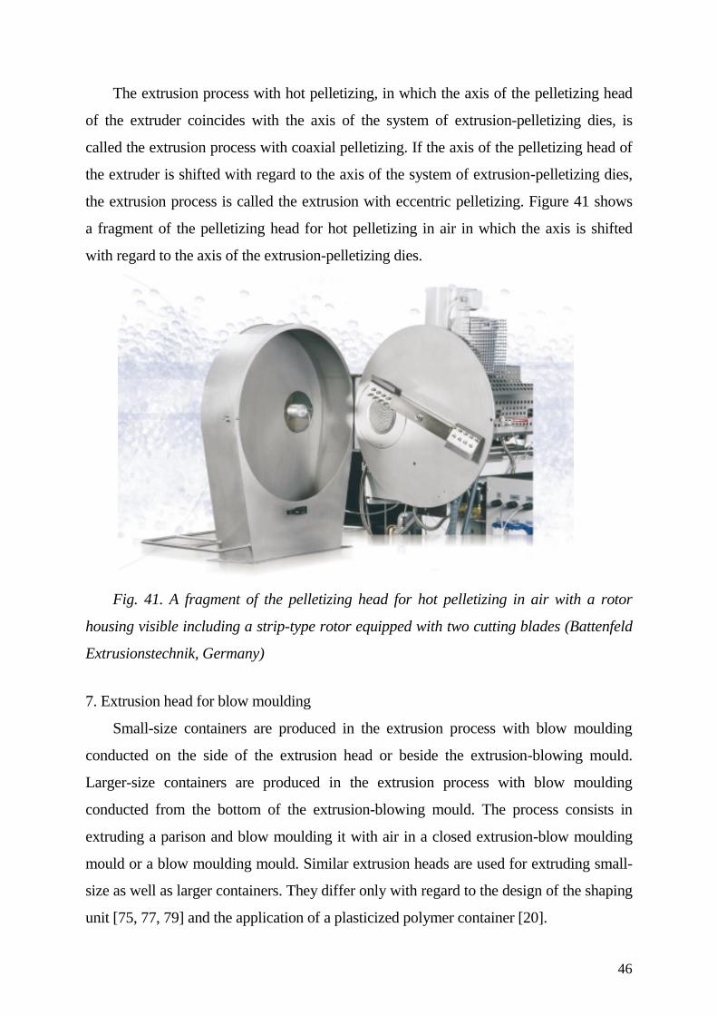
The extrusion process with hot pelletizing, in which the axis of the pelletizing head
of the extruder coincides with the axis of the system of extrusion-pelletizing dies, is
called the extrusion process with coaxial pelletizing. If the axis of the pelletizing head of
the extruder is shifted with regard to the axis of the system of extrusion-pelletizing dies,
the extrusion process is called the extrusion with eccentric pelletizing. Figure 41 shows
a fragment of the pelletizing head for hot pelletizing in air in which the axis is shifted
with regard to the axis of the extrusion-pelletizing dies.
Fig. 41. A fragment of the pelletizing head for hot pelletizing in air with a rotor
housing visible including a strip-type rotor equipped with two cutting blades (Battenfeld
Extrusionstechnik, Germany)
7. Extrusion head for blow moulding
Small-size containers are produced in the extrusion process with blow moulding
conducted on the side of the extrusion head or beside the extrusion-blowing mould.
Larger-size containers are produced in the extrusion process with blow moulding
conducted from the bottom of the extrusion-blowing mould. The process consists in
extruding a parison and blow moulding it with air in a closed extrusion-blow moulding
mould or a blow moulding mould. Similar extrusion heads are used for extruding small-
size as well as larger containers. They differ only with regard to the design of the shaping
unit [75, 77, 79] and the application of a plasticized polymer container [20].
47
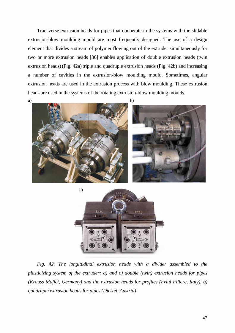
Transverse extrusion heads for pipes that cooperate in the systems with the slidable
extrusion-blow moulding mould are most frequently designed. The use of a design
element that divides a stream of polymer flowing out of the extruder simultaneously for
two or more extrusion heads [36] enables application of double extrusion heads (twin
extrusion heads) (Fig. 42a) triple and quadruple extrusion heads (Fig. 42b) and increasing
a number of cavities in the extrusion-blow moulding mould. Sometimes, angular
extrusion heads are used in the extrusion process with blow moulding. These extrusion
heads are used in the systems of the rotating extrusion-blow moulding moulds.
Fig. 42. The longitudinal extrusion heads with a divider assembled to the
plasticizing system of the extruder: a) and c) double (twin) extrusion heads for pipes
(Krauss Maffei, Germany) and the extrusion heads for profiles (Friul Filiere, Italy), b)
quadruple extrusion heads for pipes (Dietzel, Austria)
48
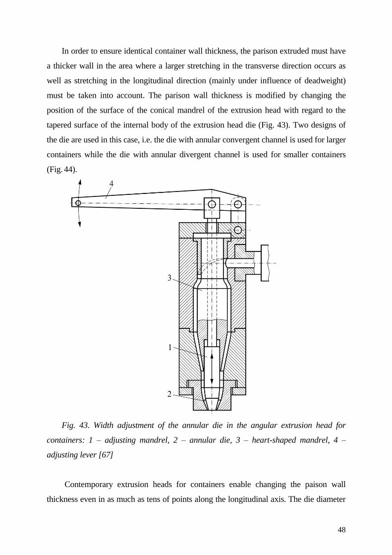
In order to ensure identical container wall thickness, the parison extruded must have
a thicker wall in the area where a larger stretching in the transverse direction occurs as
well as stretching in the longitudinal direction (mainly under influence of deadweight)
must be taken into account. The parison wall thickness is modified by changing the
position of the surface of the conical mandrel of the extrusion head with regard to the
tapered surface of the internal body of the extrusion head die (Fig. 43). Two designs of
the die are used in this case, i.e. the die with annular convergent channel is used for larger
containers while the die with annular divergent channel is used for smaller containers
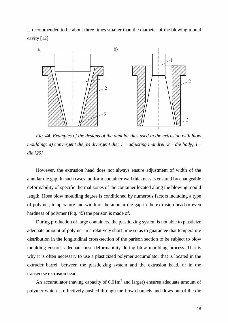
(Fig. 44).
Fig. 43. Width adjustment of the annular die in the angular extrusion head for
containers: 1 – adjusting mandrel, 2 – annular die, 3 – heart-shaped mandrel, 4 –
adjusting lever [67]
Contemporary extrusion heads for containers enable changing the paison wall
thickness even in as much as tens of points along the longitudinal axis. The die diameter
49
is recommended to be about three times smaller than the diameter of the blowing mould
cavity [12].
Fig. 44. Examples of the designs of the annular dies used in the extrusion with blow
moulding: a) convergent die, b) divergent die; 1 – adjusting mandrel, 2 – die body, 3 –
die [20]
However, the extrusion head does not always ensure adjustment of width of the
annular die gap. In such cases, uniform container wall thickness is ensured by changeable
deformability of specific thermal zones of the container located along the blowing mould
length. Hose blow moulding degree is conditioned by numerous factors including a type
of polymer, temperature and width of the annular die gap in the extrusion head or even
hardness of polymer (Fig. 45) the parison is made of.
During production of large containers, the plasticizing system is not able to plasticize
adequate amount of polymer in a relatively short time so as to guarantee that temperature
distribution in the longitudinal cross-section of the parison section to be subject to blow
moulding ensures adequate hose deformability during blow moulding process. That is
why it is often necessary to use a plasticized polymer accumulator that is located in the
extruder barrel, between the plasticizing system and the extrusion head, or in the
transverse extrusion head.
An accumulator (having capacity of 0.01m3 and larger) ensures adequate amount of
polymer which is effectively pushed through the flow channels and flows out of the die
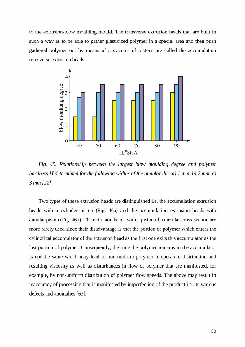
50
to the extrusion-blow moulding mould. The transverse extrusion heads that are built in
such a way as to be able to gather plasticized polymer in a special area and then push
gathered polymer out by means of a systems of pistons are called the accumulation
transverse extrusion heads.
Fig. 45. Relationship between the largest blow moulding degree and polymer
hardness H determined for the following widths of the annular die: a) 1 mm, b) 2 mm, c)
3 mm [22]
Two types of these extrusion heads are distinguished i.e. the accumulation extrusion
heads with a cylinder piston (Fig. 46a) and the accumulation extrusion heads with
annular piston (Fig. 46b). The extrusion heads with a piston of a circular cross-section are
more rarely used since their disadvantage is that the portion of polymer which enters the
cylindrical accumulator of the extrusion head as the first one exits this accumulator as the
last portion of polymer. Consequently, the time the polymer remains in the accumulator
is not the same which may lead to non-uniform polymer temperature distribution and
resulting viscosity as well as disturbances in flow of polymer that are manifested, for
example, by non-uniform distribution of polymer flow speeds. The above may result in
inaccuracy of processing that is manifested by imperfection of the product i.e. its various
defects and anomalies [63].
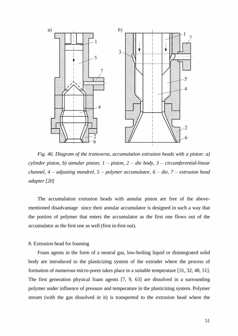
51
Fig. 46. Diagram of the transverse, accumulation extrusion heads with a piston: a)
cylinder piston, b) annular piston; 1 – piston, 2 – die body, 3 – circumferential-linear
channel, 4 – adjusting mandrel, 5 – polymer accumulator, 6 – die, 7 – extrusion head
adapter [20]
The accumulation extrusion heads with annular piston are free of the above-
mentioned disadvantage since their annular accumulator is designed in such a way that
the portion of polymer that enters the accumulator as the first one flows out of the
accumulator as the first one as well (first in-first out).
8. Extrusion head for foaming
Foam agents in the form of a neutral gas, low-boiling liquid or disintegrated solid
body are introduced to the plasticizing system of the extruder where the process of
formation of numerous micro-pores takes place in a suitable temperature [31, 32, 48, 51].
The first generation physical foam agents [7, 9, 63] are dissolved in a surrounding
polymer under influence of pressure and temperature in the plasticizing system. Polymer
stream (with the gas dissolved in it) is transported to the extrusion head where the
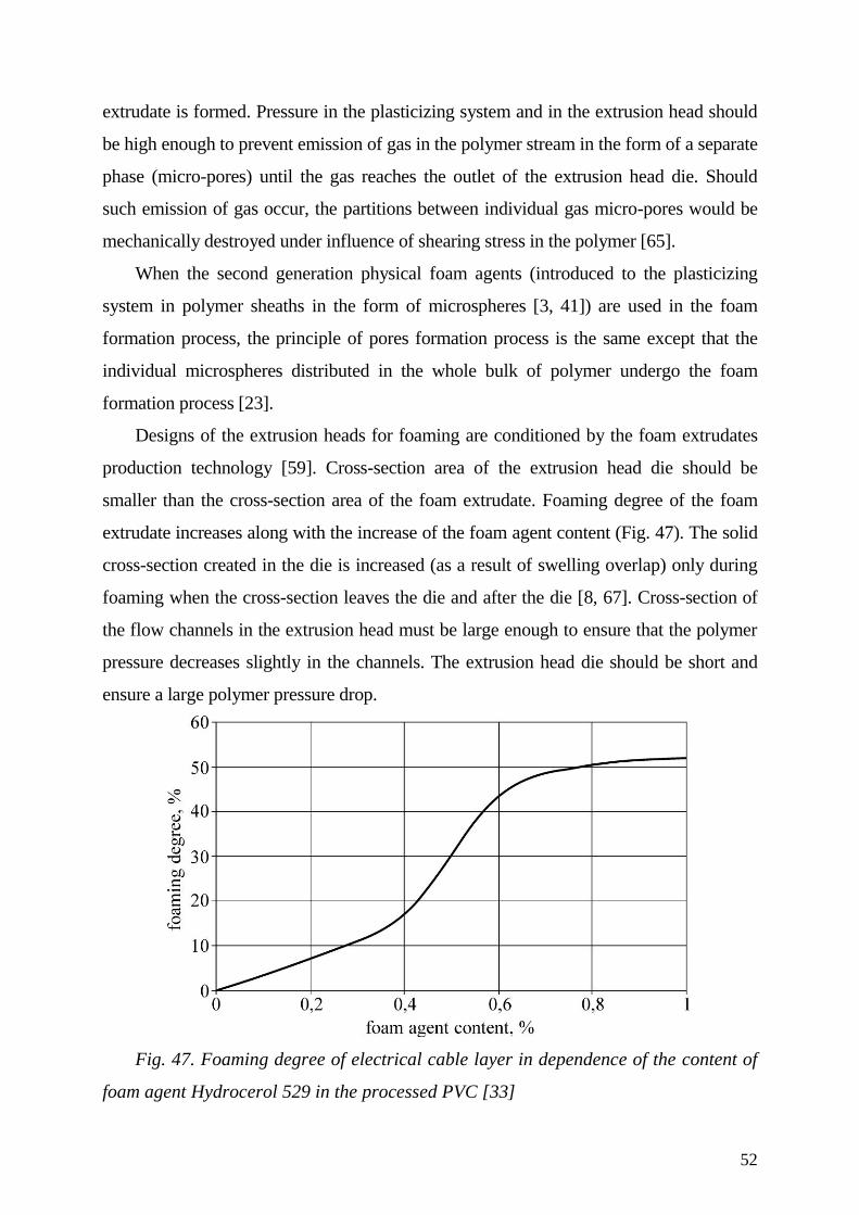
52
extrudate is formed. Pressure in the plasticizing system and in the extrusion head should
be high enough to prevent emission of gas in the polymer stream in the form of a separate
phase (micro-pores) until the gas reaches the outlet of the extrusion head die. Should
such emission of gas occur, the partitions between individual gas micro-pores would be
mechanically destroyed under influence of shearing stress in the polymer [65].
When the second generation physical foam agents (introduced to the plasticizing
system in polymer sheaths in the form of microspheres [3, 41]) are used in the foam
formation process, the principle of pores formation process is the same except that the
individual microspheres distributed in the whole bulk of polymer undergo the foam
formation process [23].
Designs of the extrusion heads for foaming are conditioned by the foam extrudates
production technology [59]. Cross-section area of the extrusion head die should be
smaller than the cross-section area of the foam extrudate. Foaming degree of the foam
extrudate increases along with the increase of the foam agent content (Fig. 47). The solid
cross-section created in the die is increased (as a result of swelling overlap) only during
foaming when the cross-section leaves the die and after the die [8, 67]. Cross-section of
the flow channels in the extrusion head must be large enough to ensure that the polymer
pressure decreases slightly in the channels. The extrusion head die should be short and
ensure a large polymer pressure drop.
Fig. 47. Foaming degree of electrical cable layer in dependence of the content of
foam agent Hydrocerol 529 in the processed PVC [33]
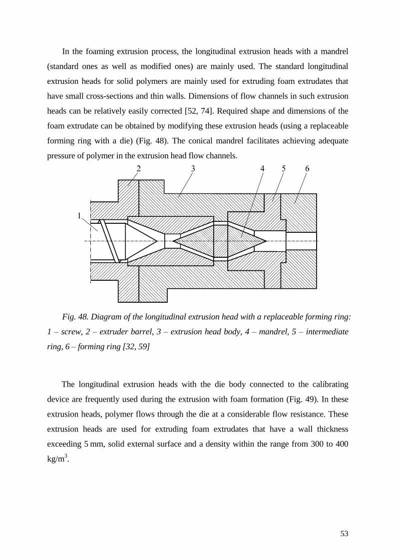
53
In the foaming extrusion process, the longitudinal extrusion heads with a mandrel
(standard ones as well as modified ones) are mainly used. The standard longitudinal
extrusion heads for solid polymers are mainly used for extruding foam extrudates that
have small cross-sections and thin walls. Dimensions of flow channels in such extrusion
heads can be relatively easily corrected [52, 74]. Required shape and dimensions of the
foam extrudate can be obtained by modifying these extrusion heads (using a replaceable
forming ring with a die) (Fig. 48). The conical mandrel facilitates achieving adequate
pressure of polymer in the extrusion head flow channels.
Fig. 48. Diagram of the longitudinal extrusion head with a replaceable forming ring:
1 – screw, 2 – extruder barrel, 3 – extrusion head body, 4 – mandrel, 5 – intermediate
ring, 6 – forming ring [32, 59]
The longitudinal extrusion heads with the die body connected to the calibrating
device are frequently used during the extrusion with foam formation (Fig. 49). In these
extrusion heads, polymer flows through the die at a considerable flow resistance. These
extrusion heads are used for extruding foam extrudates that have a wall thickness
exceeding 5 mm, solid external surface and a density within the range from 300 to 400
kg/m3.
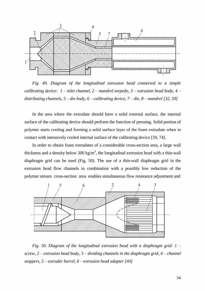
54
Fig. 49. Diagram of the longitudinal extrusion head connected to a simple
calibrating device: 1 – inlet channel, 2 – mandrel torpedo, 3 – extrusion head body, 4 –
distributing channels, 5 – die body, 6 – calibrating device, 7 – die, 8 – mandrel [32, 59]
In the area where the extrudate should have a solid external surface, the internal
surface of the calibrating device should perform the function of pressing. Solid portion of
polymer starts cooling and forming a solid surface layer of the foam extrudate when in
contact with intensively cooled internal surface of the calibrating device [59, 74].
In order to obtain foam extrudates of a considerable cross-section area, a large wall
thickness and a density below 300 kg/m3, the longitudinal extrusion head with a thin-wall
diaphragm grid can be used (Fig. 50). The use of a thin-wall diaphragm grid in the
extrusion head flow channels in combination with a possibly low reduction of the
polymer stream cross-section area enables simultaneous flow resistance adjustment and
Fig. 50. Diagram of the longitudinal extrusion head with a diaphragm grid: 1 –
screw, 2 – extrusion head body, 3 – dividing channels in the diaphragm grid, 4 – channel
stoppers, 5 – extruder barrel, 6 – extrusion head adapter [44]
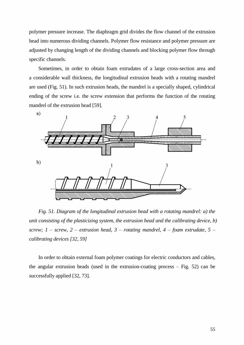
55
polymer pressure increase. The diaphragm grid divides the flow channel of the extrusion
head into numerous dividing channels. Polymer flow resistance and polymer pressure are
adjusted by changing length of the dividing channels and blocking polymer flow through
specific channels.
Sometimes, in order to obtain foam extrudates of a large cross-section area and
a considerable wall thickness, the longitudinal extrusion heads with a rotating mandrel
are used (Fig. 51). In such extrusion heads, the mandrel is a specially shaped, cylindrical
ending of the screw i.e. the screw extension that performs the function of the rotating
mandrel of the extrusion head [59].
Fig. 51. Diagram of the longitudinal extrusion head with a rotating mandrel: a) the
unit consisting of the plasticizing system, the extrusion head and the calibrating device, b)
screw; 1 – screw, 2 – extrusion head, 3 – rotating mandrel, 4 – foam extrudate, 5 –
calibrating devices [32, 59]
In order to obtain external foam polymer coatings for electric conductors and cables,
the angular extrusion heads (used in the extrusion-coating process – Fig. 52) can be
successfully applied [32, 73].
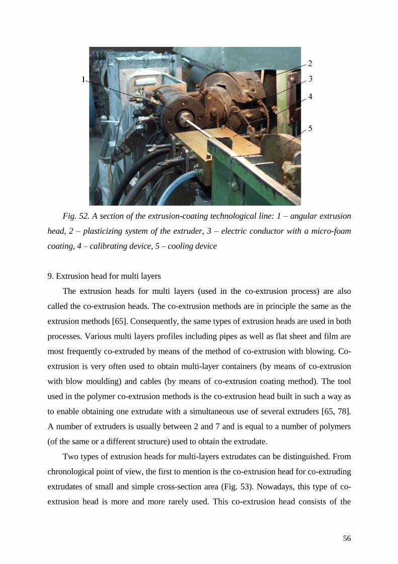
56
Fig. 52. A section of the extrusion-coating technological line: 1 – angular extrusion
head, 2 – plasticizing system of the extruder, 3 – electric conductor with a micro-foam
coating, 4 – calibrating device, 5 – cooling device
9. Extrusion head for multi layers
The extrusion heads for multi layers (used in the co-extrusion process) are also
called the co-extrusion heads. The co-extrusion methods are in principle the same as the
extrusion methods [65]. Consequently, the same types of extrusion heads are used in both
processes. Various multi layers profiles including pipes as well as flat sheet and film are
most frequently co-extruded by means of the method of co-extrusion with blowing. Co-
extrusion is very often used to obtain multi-layer containers (by means of co-extrusion
with blow moulding) and cables (by means of co-extrusion coating method). The tool
used in the polymer co-extrusion methods is the co-extrusion head built in such a way as
to enable obtaining one extrudate with a simultaneous use of several extruders [65, 78].
A number of extruders is usually between 2 and 7 and is equal to a number of polymers
(of the same or a different structure) used to obtain the extrudate.
Two types of extrusion heads for multi-layers extrudates can be distinguished. From
chronological point of view, the first to mention is the co-extrusion head for co-extruding
extrudates of small and simple cross-section area (Fig. 53). Nowadays, this type of co-
extrusion head is more and more rarely used. This co-extrusion head consists of the
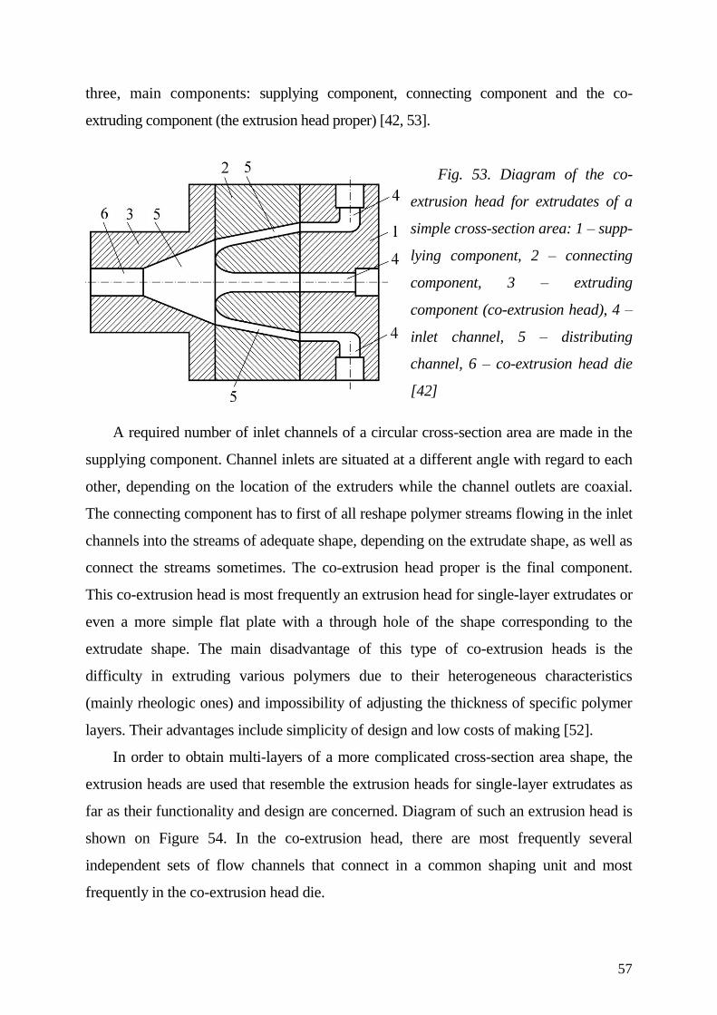
57
three, main components: supplying component, connecting component and the co-
extruding component (the extrusion head proper) [42, 53].
Fig. 53. Diagram of the co-
extrusion head for extrudates of a
simple cross-section area: 1 – supp-
lying component, 2 – connecting
component, 3 – extruding
component (co-extrusion head), 4 –
inlet channel, 5 – distributing
channel, 6 – co-extrusion head die
[42]
A required number of inlet channels of a circular cross-section area are made in the
supplying component. Channel inlets are situated at a different angle with regard to each
other, depending on the location of the extruders while the channel outlets are coaxial.
The connecting component has to first of all reshape polymer streams flowing in the inlet
channels into the streams of adequate shape, depending on the extrudate shape, as well as
connect the streams sometimes. The co-extrusion head proper is the final component.
This co-extrusion head is most frequently an extrusion head for single-layer extrudates or
even a more simple flat plate with a through hole of the shape corresponding to the
extrudate shape. The main disadvantage of this type of co-extrusion heads is the
difficulty in extruding various polymers due to their heterogeneous characteristics
(mainly rheologic ones) and impossibility of adjusting the thickness of specific polymer
layers. Their advantages include simplicity of design and low costs of making [52].
In order to obtain multi-layers of a more complicated cross-section area shape, the
extrusion heads are used that resemble the extrusion heads for single-layer extrudates as
far as their functionality and design are concerned. Diagram of such an extrusion head is
shown on Figure 54. In the co-extrusion head, there are most frequently several
independent sets of flow channels that connect in a common shaping unit and most
frequently in the co-extrusion head die.
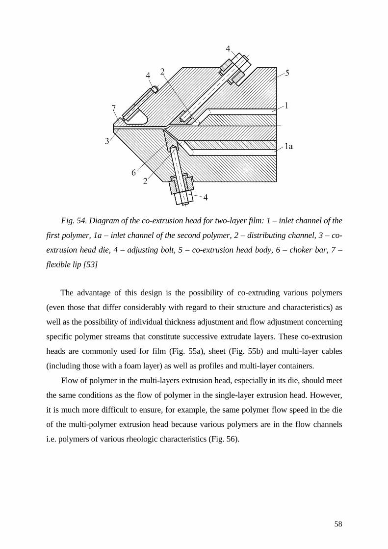
58
Fig. 54. Diagram of the co-extrusion head for two-layer film: 1 – inlet channel of the
first polymer, 1a – inlet channel of the second polymer, 2 – distributing channel, 3 – co-
extrusion head die, 4 – adjusting bolt, 5 – co-extrusion head body, 6 – choker bar, 7 –
flexible lip [53]
The advantage of this design is the possibility of co-extruding various polymers
(even those that differ considerably with regard to their structure and characteristics) as
well as the possibility of individual thickness adjustment and flow adjustment concerning
specific polymer streams that constitute successive extrudate layers. These co-extrusion
heads are commonly used for film (Fig. 55a), sheet (Fig. 55b) and multi-layer cables
(including those with a foam layer) as well as profiles and multi-layer containers.
Flow of polymer in the multi-layers extrusion head, especially in its die, should meet
the same conditions as the flow of polymer in the single-layer extrusion head. However,
it is much more difficult to ensure, for example, the same polymer flow speed in the die
of the multi-polymer extrusion head because various polymers are in the flow channels
i.e. polymers of various rheologic characteristics (Fig. 56).
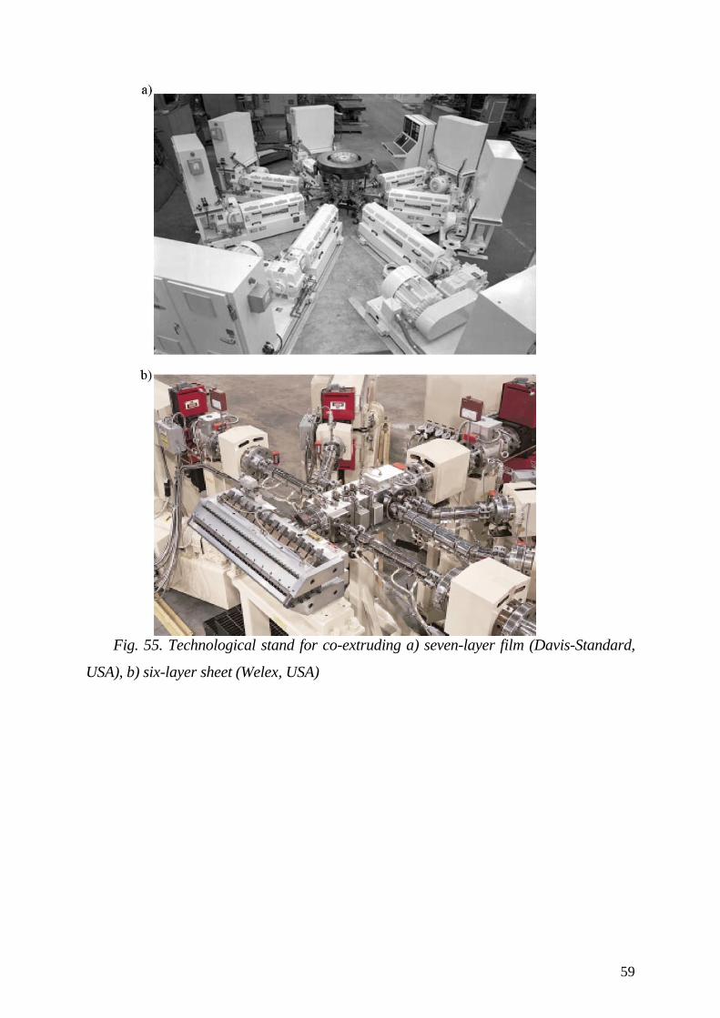
59
Fig. 55. Technological stand for co-extruding a) seven-layer film (Davis-Standard,
USA), b) six-layer sheet (Welex, USA)
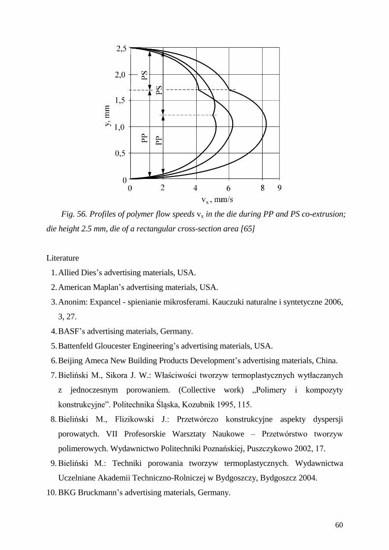
60
Fig. 56. Profiles of polymer flow speeds vx in the die during PP and PS co-extrusion;
die height 2.5 mm, die of a rectangular cross-section area [65]
Literature
1. Allied Dies’s advertising materials, USA.
2. American Maplan’s advertising materials, USA.
3. Anonim: Expancel - spienianie mikrosferami. Kauczuki naturalne i syntetyczne 2006,
3, 27.
4. BASF’s advertising materials, Germany.
5. Battenfeld Gloucester Engineering’s advertising materials, USA.
6. Beijing Ameca New Building Products Development’s advertising materials, China.
7. Bieliński M., Sikora J. W.: Właściwości tworzyw termoplastycznych wytłaczanych
z jednoczesnym porowaniem. (Collective work) „Polimery i kompozyty
konstrukcyjne”. Politechnika Śląska, Kozubnik 1995, 115.
8. Bieliński M., Flizikowski J.: Przetwórczo konstrukcyjne aspekty dyspersji
porowatych. VII Profesorskie Warsztaty Naukowe – Przetwórstwo tworzyw
polimerowych. Wydawnictwo Politechniki Poznańskiej, Puszczykowo 2002, 17.
9. Bieliński M.: Techniki porowania tworzyw termoplastycznych. Wydawnictwa
Uczelniane Akademii Techniczno-Rolniczej w Bydgoszczy, Bydgoszcz 2004.
10. BKG Bruckmann’s advertising materials, Germany.
61
11. Brampton Engineering’s advertising materials, Canada.
12. Chevron Phillips Chemical’s advertising materials, USA.
13. Cincinnati-Milacron Extrusion’s advertising materials, Austria.
14. Cloeren’s advertising materials, USA.
15. Crown Machine’s advertising materials, USA.
16. Cykana D.: The Extrusion Technicians Toolbox. Profile Extrusion. The Society of
Plastics Engineers, New Holland 2004.
17. Davis-Standard’s advertising materials, USA.
18. Deutschland Patent 2 557 166 (1975).
19. Deutschland Patent 3 934 592 (1989).
20. DSM Thermoplastic Elastomers’s advertising materials, USA.
21. DuPont Engineering Polymers’s advertising materials, USA.
22. Econ-Kundenberatung’s advertising materials, Austria.
23. Expancel’s advertising materials, Sweden.
24. ETA Kunststofftechnologie’s advertising materials, Germany.
25. Extrusion Auxiliary Services’s advertising materials, USA.
26. Extrusion Dies Industries’s advertising materials, USA.
27. Ferguson J., Kembłowski Z.: Reologia stosowana płynów. Wydawnictwo Marcus,
Łódź 1995.
28. Fisher P., Wortberg J.: New Spiral Mandrel Dies. Paper presented at the SKZ
Conference on Innovations in Extrusion, Würzburg, Niemcy 1998.
29. Fischer P.: The future for pipe and tube die design: helix or spiral. British Plastics and
Rubber 2006, May, 4.
30. Friul Filiere’s advertising materials, Italy.
31. Garbacz T.: Wybrane charakterystyki procesu wytłaczania porującego. Teka Komisji
Budowy i Eksploatacji Maszyn, Elektrotechniki, Budownictwa 2003, 1, 129.
32. Garbacz T., Tor A.: Wpływ zawartości środka porującego na właściwości użytkowe
zewnętrznych powłok kabli wytwarzanych metodą wytłaczania porującego. Polimery
2007, 4, 286.

62
33. Garbacz T.: Wybrane aspekty wytwarzania powłok w procesie porującego
współwytłaczania powlekającego. XIII Profesorskie Warsztaty Naukowe –
Przetwórstwo tworzyw polimerowych. Polska Akademia Nauk, Lublin 2008, 17.
34. Greiner Extrusion’s advertising materials, Austria.
35. Gross H.: Flexible Werkzeugwände. Kunststoffe 2003, 8, 28.
36. Guill Tool & Engineering’s advertising materials, USA.
37. Gupta M., Zacarias F., Schrader S.: Balancing of Profile Dies using Three-
Dimensional Flow Simulation. Annual Meeting. The Polymer Processing Society,
Yamagata, Japan 2006, 122.
38. Hai-Nice Plastics Mould Faktory’s advertising materials, China.
39. Hans Weber’s advertising materials, Germany.
40. Inteligent Pelletizing Solutions’s advertising materials, Germany.
41. Jönsson L., Rosskothen K. R.: Microspheres – a Universal, Effective Blowing Agent.
Kunststoffe Plast Europe 2003, 7, 40.
42. Kostic M. M., Reifschneider G. L.: Design of Extrusion Dies. Annual Technical
Conference. The Society of Plastics Engineers, Chicago, USA 2004, 633.
43. Krauss Maffei’s advertising materials, Germany.
44. Michaeli W.: Extrusion Dies for Plastics and Rubber. Hanser Publishers, Munich
1992.
45. OCF’s advertising materials, Italy.
46. Polish Patent 108291 (1976).
47. Polish Patent 182449 (1997).
48. Polish Patent Application 376808 (2005).
49. Polish Patent Application 380161 (2006).
50. Premier Dies’s advertising materials, USA.
51. Qiong Z., Chan-Bo C.: Exo-endothermic Blowing Agent and its Foaming Behavior.
Journal of Cellular Plastics 2005, 3, 225.
52. Rauwendal Ch.: Polymer Extrusion. Carl Hanser Verlag, Munich, Vienna, New York
1986.
53. Rauwendaal Ch.: Understanding Extrusion. Carl Hanser Verlag, Munich 1998.
54. Reifenhäuser Extrusion’s advertising materials, Germany.
63
55. Rieter Automatic’s advertising materials, Germany.
56. Scheer Bay’s advertising materials, USA.
57. Schöppner V., Limper A., Rübbelke I.: Development of Die Concept with a Rotating
Distributor Geometry. Europe/Africa Regional Meeting. The Polymer Processing
Society, Gothenburg, Sweden 2007, 1.
58. Shaoxing Siwell Plastics Engineering and Technology’s advertising materials, China.
59. Sikora J. W., Bieliński M.: Głowice do wytłaczania porującego kształtowników.
(Collective work) „Postęp w przetwórstwie tworzyw termoplastycznych”.
Politechnika Częstochowska, Częstochowa 1995, 209.
60. Sikora J. W.: Granulator do wtórnego granulowania na zimno. Polimery 1998, 3, 187.
61. Sikora J. W.: Wpływ kąta ostrza noża granulatora na efektywność konstrukcyjną
procesu wytłaczania z granulowaniem polietylenu. Polimery 2002, 3, 196.
62. Sikora R.: Proces granulowania tworzyw wielkocząsteczkowych. Praca zbiorowa
„Obróbka materiałów niemetalowych”. Wydawnictwa Uczelniane Politechniki
Rzeszowskiej, Rzeszów 1990, 139.
63. Sikora R.: Podstawy przetwórstwa tworzyw wielkocząsteczkowych. Wydawnictwo
Politechniki Lubelskiej, Lublin 1992.
64. Sikora R., Masztaleruk P.: Noże granulatora do polietylenu. Polimery 1992, 9, 421.
65. Sikora R.: Przetwórstwo tworzyw wielkocząsteczkowych. Wydawnictwo Edukacyjne,
Warszawa 1993.
66. Sikora R.: Obróbka tworzyw wielkocząsteczkowych, Wydawnictwo Edukacyjne.
Warszawa 1996.
67. Sikora R. (editor of collective work): Przetwórstwo tworzyw polimerowych.
Podstawy logiczne, formalne i terminologiczne. Wydawnictwo Politechniki
Lubelskiej, Lublin 2006.
68. Smith E. D., Wang Q.: Incorporating Adjustable Features in the Optimal Design of
Polymer Sheet Extrusion Dies. Journal of Manufacturing Science and Engineering
2006, 1, 11.
69. Sun Y. and Gupta M.: Effect of Elongational Viscosity on the Flow in a Flat Die.
International Polymer Processing 2003, 18, 356.
64
70. Sun Y., Gupta M.: Optimization of a Flat Die Geometry. Annual Technical
Conference. The Society of Plastics Engineers, Chicago, USA 2004, 3307.
71. Sun Y., Gupta M.: Effect of Elongational Viscosity on the Flow in a Spiral Die.
Annual Technical Conference. The Society of Plastics Engineers, Chicago, USA
2004, 86.
72. Ticona’s advertising materials, USA.
73. Tor. A.: Selected Problems of Extrusion Process of Cellular Cable Layers. 10th
International Symposium “Advances in Mechanical Engineering”. Gdansk
University of Technology, Gdańsk – Gdynia 2007, 171.
74. Tor A.: Charakterystyka procesu wytłaczania porującego. Eksploatacja i
Niezawodność 2005, 2, 18.
75. US Patent 5 221 540 (1992).
76. US Patent 5 643 363 (1995).
77. US Patent 5 776 519 (1997).
78. US Patent 7 008 577 (2001).
79. US Patent 7 267 541 (2005).
80. Vaddiraju R. S.: Extrusion Simulation and Optimalization of Profile Die Design.
Master thesis. Northern Illinois University, DeKalb 2004.
81. Verbruggen Emmeloord’s advertising materials, the Netherlands.
82. Wayne Machine & Die Company’s advertising materials, USA.