Design of Control Circuit for an Electro-Magnetic Gene GunDesign of Control Circuit for an...
6
Design of Control Circuit for an Electro-Magnetic Gene Gun PING-YIN CHEN 1 PEI-HWA HUANG 2 Department of Electrical Engineering National Taiwan Ocean University 2 Pei-Ning Road, Keelung TAIWAN 1 [email protected] http://www.ntou.edu.tw 2 [email protected] http://www.ntou.edu.tw FANG-CHENG JHU 3 CHAO-CHENG LU 4 Department of Electronics Engineering National Changhua University of Education 1Jin-De Road, Changhua City TAIWAN 3,4 [email protected] http://www.ncue.edu.tw Abstract: - A control circuit of a gene gun, which employs electromagnetic force as power source based on electromagnetic mechanics, is proposed in this paper. In the control circuit, a single capacitor stores energy and instantaneously discharges to an electromagnetic energy device in the gene gun, and thus provides micro-projectiles with electromagnetic force to generate strike force. Discussions in this paper are mainly focused on the control circuit, the strike force generated from the discharge effect of the electromagnetic device, derivative of the electromagnetic strike force theorem, experiments and analysis on each module of the control circuit, and test of an actually built gene gun. This study has disclosed that the proposed electromagnetic gene gun was able to energize micro-projectiles generating strike force as high as 4500psi. The proposed gene gun with broader range of the strike force is apparently better than the third-generation (high pressure gas type) gene guns, with more features including lower cost of manufacturing and convenience of operation. The validness and feasibility of the proposed gene gun have been tested and verified in the experiments. Key Words: - Electromagnetically Powered, Impulse Force, Gene Gun. 1 Introduction Gene guns are also called particle guns. During the process of genetic engineering, DNA (Deoxyribonucleic Acid) is first extracted from donor cells. Then by dividing DNA and vectors with restriction enounces, connecting exogenous gene of DNA fragments to carriers with DNA ligase and thus forming molecules of DNA recombination. The molecules of DNA recombination are then delivered into receptor molecules with gene guns where small gold or tungsten particles coated with DNA are accelerated at high speed and then penetrate cell walls and/or cell membranes, thus the DNA are delivered into target cells and the process of gene transfer is completed. In 1987, Prof. John Sanford, (Cornell University, the United States), invented a gunpowder driven gene gun that shot micro-projectiles [1] which was the very first- generation gene gun [1], [2]. Later, the second- generation gene guns, high voltage discharge type gene guns, were developed [3], [4], which utilized high temperature gas (vaporizing a drop of water produced by high voltage discharging) for driving accelerators. The third-generation gene guns were high-pressure gas type gene guns [5]-[14] in which high-pressure helium was often adapted as power source. But the exhaustion of such high-pressure gas might cause additional problems. Furthermore, helium was expensive. A gene gun designed based on electromagnetic mechanics with lower cost and ease of use is to be proposed in this paper.. As mentioned above, the process of gene transfer is the process of delivering exogenous genes into living cell or tissue with high speed “Particles” and keeping the exogenous gene intact. The “Particles” are small sticky gold or tungsten particles with the diameter of 0.4-2.0μm. Because the “Particles” cannot be accelerated directly, they must be attached on projectiles such that the DNA may be accelerated along with projectiles to high velocity and then transferred into acceptors. It is therefore that gene guns are critical technologies in biotech industry. Proc. of the 5th WSEAS/IASME Int. Conf. on Electric Power Systems, High Voltages, Electric Machines, Tenerife, Spain, December 16-18, 2005 (pp632-637)
Transcript of Design of Control Circuit for an Electro-Magnetic Gene GunDesign of Control Circuit for an...

Design of Control Circuit for an Electro-Magnetic Gene Gun
PING-YIN CHEN1 PEI-HWA HUANG2 Department of Electrical Engineering
National Taiwan Ocean University 2 Pei-Ning Road, Keelung
TAIWAN [email protected] http://www.ntou.edu.tw
[email protected] http://www.ntou.edu.tw
FANG-CHENG JHU3 CHAO-CHENG LU4 Department of Electronics Engineering
National Changhua University of Education 1Jin-De Road, Changhua City
TAIWAN 3,[email protected] http://www.ncue.edu.tw
Abstract: - A control circuit of a gene gun, which employs electromagnetic force as power source based on electromagnetic mechanics, is proposed in this paper. In the control circuit, a single capacitor stores energy and instantaneously discharges to an electromagnetic energy device in the gene gun, and thus provides micro-projectiles with electromagnetic force to generate strike force. Discussions in this paper are mainly focused on the control circuit, the strike force generated from the discharge effect of the electromagnetic device, derivative of the electromagnetic strike force theorem, experiments and analysis on each module of the control circuit, and test of an actually built gene gun. This study has disclosed that the proposed electromagnetic gene gun was able to energize micro-projectiles generating strike force as high as 4500psi. The proposed gene gun with broader range of the strike force is apparently better than the third-generation (high pressure gas type) gene guns, with more features including lower cost of manufacturing and convenience of operation. The validness and feasibility of the proposed gene gun have been tested and verified in the experiments. Key Words: - Electromagnetically Powered, Impulse Force, Gene Gun. 1 Introduction Gene guns are also called particle guns. During the process of genetic engineering, DNA (Deoxyribonucleic Acid) is first extracted from donor cells. Then by dividing DNA and vectors with restriction enounces, connecting exogenous gene of DNA fragments to carriers with DNA ligase and thus forming molecules of DNA recombination. The molecules of DNA recombination are then delivered into receptor molecules with gene guns where small gold or tungsten particles coated with DNA are accelerated at high speed and then penetrate cell walls and/or cell membranes, thus the DNA are delivered into target cells and the process of gene transfer is completed. In 1987, Prof. John Sanford, (Cornell University, the United States), invented a gunpowder driven gene gun that shot micro-projectiles [1] which was the very first- generation gene gun [1], [2]. Later, the second- generation gene guns, high voltage discharge type gene guns, were developed [3], [4], which utilized
high temperature gas (vaporizing a drop of water produced by high voltage discharging) for driving accelerators. The third-generation gene guns were high-pressure gas type gene guns [5]-[14] in which high-pressure helium was often adapted as power source. But the exhaustion of such high-pressure gas might cause additional problems. Furthermore, helium was expensive. A gene gun designed based on electromagnetic mechanics with lower cost and ease of use is to be proposed in this paper.. As mentioned above, the process of gene transfer is the process of delivering exogenous genes into living cell or tissue with high speed “Particles” and keeping the exogenous gene intact. The “Particles” are small sticky gold or tungsten particles with the diameter of 0.4-2.0µm. Because the “Particles” cannot be accelerated directly, they must be attached on projectiles such that the DNA may be accelerated along with projectiles to high velocity and then transferred into acceptors. It is therefore that gene guns are critical technologies in biotech industry.
Proc. of the 5th WSEAS/IASME Int. Conf. on Electric Power Systems, High Voltages, Electric Machines, Tenerife, Spain, December 16-18, 2005 (pp632-637)

With a better gene gun, skills for biotechnology may be improved and the probability of success may be increased. But to date, documents on the research and development of gene guns are still rare [1]-[14].
This paper is organized as following. In section 2, theoretical results on electromagnetic impacts are described. In section 3, the basic structure of the control circuit and opperation of the proposed gene gun are introduced. In section 4, design of control circuit. The results of measured impact force of the actual hardware are shown in section 5 which demonstrates the correctness and the feasibility of the control circuit for the proposed gene gun. 2 Electromagnetic Impact According to the Faraday’s law of electromagnetic induction [15], electric energy is induced along with magnetic fields. The relation between voltage V and current I in a circuit may be described by the following equation:
ℜ=℘+ IV (1)
where
℘: Induced voltage,
ℜ : Resistance in a circuit.
Both the electric charge q and the current I vary with time t and may be expressed as:
dtIdq = (2)
Thus, the relation among the voltage, electric charge, current and time may be further described as:
RdtIdtIdtVIVdq 2+−℘== (3)
According to the Faraday’s law of electromagnetic induction:
ddtΦ
℘= − (4)
where
Φ : flux.
Equation (4) describes that the induced voltage equals to the negative time variance of flux in a static close loop. The minus sign in equation (4) guarantees the current induced by the induced voltage flows in a direction against the variance of the flux. Rewrite equation (3) according to equation (4) and then equation (3) may be expressed as:
dtIdIdtIdtIdtVIdqV
ℜ+Φ=
ℜ+−℘==2
2
(5)
If the flux is invariant, according to Ohm’s Law which I and ℜ obey, dtI ℜ2 is the time variance of electric energy that can be calculated, and ΦdI stands for the energy generated by the circuit. Thus, if
dtI ℜ2 is not considered, equation (5) may be simplified as:
exdW I d= Φ (6)
where
exW :energy generated by external power source.
The exdW in equation (6) may be positive or negative. If it is positive, that means the direction of the flux generated by current I and the direction of the current I are identical in the circuit if there’s no magnetic hysterics that consumes energy in the circuit, the magnetic energy in the circuit equals to
exdW . Because the magnetic energy varies, it can be applied to circuits for generating force or torque.
Considering the N -turn round coil shown in Fig 1. Let the length from the z-axis to the inner side and outer side of the coil to be 1b and 2b respectively, then the flux density B at any point inside the coil may be expressed as:
Fig. 1 N-turn round coil with current I
Proc. of the 5th WSEAS/IASME Int. Conf. on Electric Power Systems, High Voltages, Electric Machines, Tenerife, Spain, December 16-18, 2005 (pp632-637)
∫= dBB
∫−+−
−=
d
z
zzbb
dzbbIN0
23
2'212
'2120
])()[(2
)(µa
]lnln
[
)(2
12
121
222
211
12
12
222
2
12
0
bbz
bbzz
bbz
bbzz
bbIN
z
++
++−
++
++
−=
µa
(7)
Because the magnetic force F q= ×u B , the magnetic force inside the coil is:
=F uq B×
]lnln
[
)(2
12
121
222
211
12
12
222
2
12
0
bbz
bbzz
bbz
bbzz
bbINqu z
++
++−
++
++
−×=
µa
(8)
where
u : velocity of moving electric charge. Equation (8) means the moving electric charge generates current and the current generates magnetic field, thus the current is generated along with the magnetic field. Further, force F may also be expressed as:
dtdmm ua ==F (9)
where
m:velocity of matter;
a:acceleration. By combining equation (8) and equation (9), equation dm q
d t= ×
u u B is derived. If the mechanics
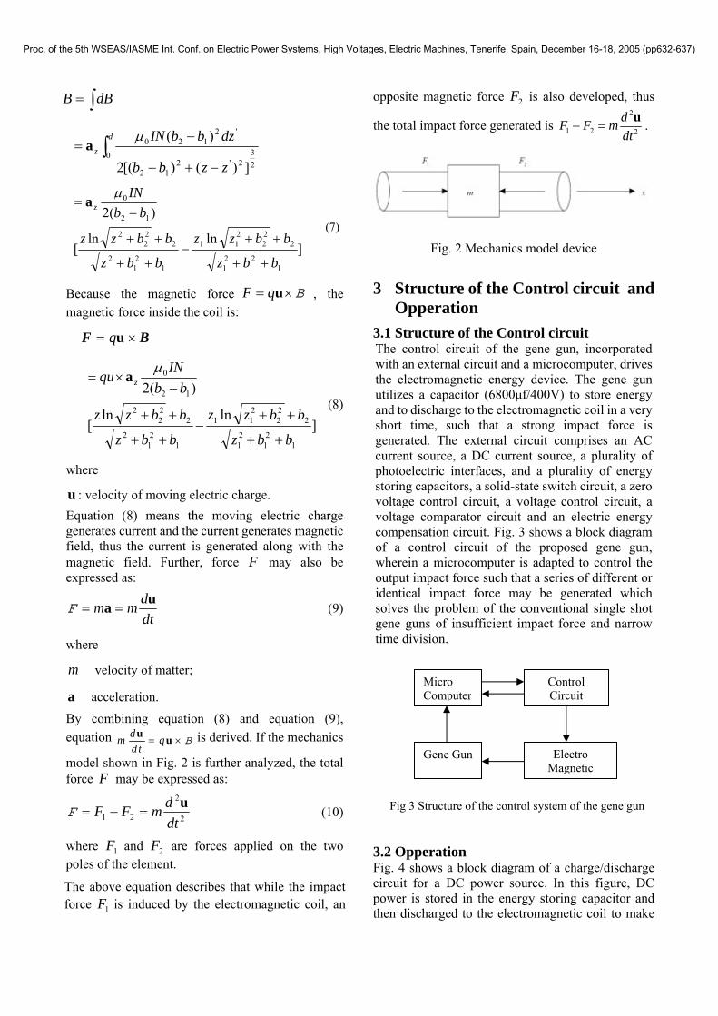
model shown in Fig. 2 is further analyzed, the total force F may be expressed as:
2
2
21 dtdmFF u
=−=F (10)
where 1F and 2F are forces applied on the two poles of the element.
The above equation describes that while the impact force 1F is induced by the electromagnetic coil, an
opposite magnetic force 2F is also developed, thus
the total impact force generated is 2
1 2 2
dF F mdt
− =u .
Fig. 2 Mechanics model device
3 Structure of the Control circuit and
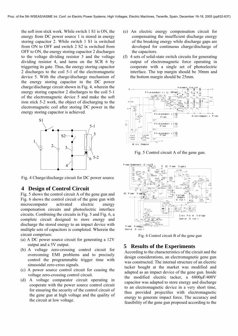
Opperation 3.1 Structure of the Control circuit The control circuit of the gene gun, incorporated with an external circuit and a microcomputer, drives the electromagnetic energy device. The gene gun utilizes a capacitor (6800µf/400V) to store energy and to discharge to the electromagnetic coil in a very short time, such that a strong impact force is generated. The external circuit comprises an AC current source, a DC current source, a plurality of photoelectric interfaces, and a plurality of energy storing capacitors, a solid-state switch circuit, a zero voltage control circuit, a voltage control circuit, a voltage comparator circuit and an electric energy compensation circuit. Fig. 3 shows a block diagram of a control circuit of the proposed gene gun, wherein a microcomputer is adapted to control the output impact force such that a series of different or identical impact force may be generated which solves the problem of the conventional single shot gene guns of insufficient impact force and narrow time division.
Fig 3 Structure of the control system of the gene gun 3.2 Opperation Fig. 4 shows a block diagram of a charge/discharge circuit for a DC power source. In this figure, DC power is stored in the energy storing capacitor and then discharged to the electromagnetic coil to make
Micro Computer
Electro Magnetic
Control Circuit
Gene Gun
Proc. of the 5th WSEAS/IASME Int. Conf. on Electric Power Systems, High Voltages, Electric Machines, Tenerife, Spain, December 16-18, 2005 (pp632-637)
11021103
1101
1004
1002
1001
1003+-
904
905903+-
1005
901
Photoconductivity Plant
Micro Computer
Photoconductivity
Plant
Plant
Electromagnetic Plant
Hardware Switch
Hardware Switch
Hardware Switch
Hardware Switch
ProgrammerTransfer
803
G1
G1
G1
G1
G2
PC817
100uF50V
6K1N5349
400V6800uF
DT95N-B
DT95N-A
DD55F-A
DD55F-B
9062k
A1
A2
A3
R R R
B1 C1 D1
D2
D3
C2
C3
B2
B3
B1B2B3
C1C2C3
D1D2D3
802
C1815
C1815
902C1815
804
801 50RC1815
12
3
1
2
3
12
3
1 2
3
12
43
60W
B
A
S
T
D
C
S5T
R
1004
G1
CD
Plant
Photoconductivity
Photoconductivity
Frequency
Output
DecodeMultichannel
Output
P3205
202
204
207
206
209
P1
406404
405
403
AC1
V+2
AC 3
V- 4
201
S4S3
402
AC1
V+2
AC3
V-4
401
503
502
P2
302
303
602+603
+
601604
606+ 605
301
607
609
610
+ 612
702
714
715
712
705
704
711
713
703
Vin1
GND
2
Vout 3701
710A
710B
R
T
S
G1
AC Power Supply
CompensateDC Power Supply
Voltage
Zero Point Voltage
Power Supply
501
S1 611
G1
G2
G2
Vin1
GND
2
Vout 3613
706G1
G1
G1
+ 608
S11MD5V
70HF12
TT56N
15k
1k
10k
1N5349
PC817 1800uF200V
1800uF200V70HF12
70HF12
70HF12
1N4007
820uF400V
BTA41
GV447
KBPC351015A
DB104
2k/20W
10k20W
10k/20W
1N4007
PC817
2P4M
1k
1k/2W
PC817
600R240W
1N5349100uF/35V
7805
2P4M
10k
LED
1k
7812
200k
1k
100k
LM358
LM358
470k
13k
S2
1N4007
47uF250V
1k
4076.8k/5W2W
G1
2W
10k203 RE1
EDR0500
2k208
2k210
5W
5W
RE2EDR0500
RE2EDR0500
1
23
1 2
4 3
1
4
2
3
12
3 4
4
62
1
1 2
4 31
2
4
3
1 2
345
64
87
231
31
2
2 1
3
2
70710k
703
709LED
31
7081k
A
BC
P4
PC817
1
2
4
3G1
D
G2
Control Circuit
Compare Circuit
Power Circuit
Control Circuit
the soft iron stick work. While switch 1 S1 is ON, the energy from DC power source 1 is stored in energy storing capacitor 2. While switch 1 S1 is switched from ON to OFF and switch 2 S2 is switched from OFF to ON, the energy storing capacitor 2 discharges to the voltage dividing resistor 3 and the voltage dividing resistor 4, and turns on the SCR 6 by triggering its gate. Thus, the energy storing capacitor 2 discharges to the coil 5-1 of the electromagnetic device 5. With the charge/discharge mechanism of the energy storing capacitor in the DC power charge/discharge circuit shown in Fig. 4, wherein the energy storing capacitor 2 discharges to the coil 5-1 of the electromagnetic device 5 and make the soft iron stick 5-2 work, the object of discharging to the electromagnetic coil after storing DC power in the energy storing capacitor is achieved. Fig. 4 Charge/discharge circuit for DC power source 4 Design of Control Circuit Fig. 5 shows the control circuit A of the gene gun and Fig. 6 shows the control circuit of the gene gun with microcomputer activated electric energy compensation circuits and photoelectric interface circuits. Combining the circuits in Fig. 5 and Fig. 6, a complete circuit designed to store energy and discharge the stored energy to an impact device with multiple sets of capacitors is completed. Wherein the circuit comprises: (a) A DC power source circuit for generating a 12V
output and a 5V output. (b) A voltage zero-crossing control circuit for
overcoming EMI problems and to precisely control the programmable trigger time with sinusoidal zero-cross signals.
(c) A power source control circuit for ceasing the voltage zero-crossing control circuit.
(d) A voltage comparator circuit operating in cooperate with the power source control circuit for ensuring the security of the control circuit of the gene gun at high voltage and the quality of the circuit at low voltage.
(e) An electric energy compensation circuit for compensating the insufficient discharge energy of the breaking energy while discharge gaps are developed for continuous charge/discharge of the capacitors.
(f) 4 sets of solid-state switch circuits for generating output of electromagnetic force operating in cooperate with a single set of photoelectric interface. The top margin should be 30mm and the bottom margin should be 25mm.
Fig. 5 Control circuit A of the gene gun.
Fig. 6 Control circuit B of the gene gun 5 Results of the Experiments According to the characteristics of the circuit and the design considerations, an electromagnetic gene gun was constructed. The internal structure of an electric tacker bought at the market was modified and adapted as an impact device of the gene gun. Inside the modified electric tacker, a 6800µF/400V capacitor was adapted to store energy and discharge to an electromagnetic device in a very short time, thus provided projectiles with electromagnetic energy to generate impact force. The accuracy and feasibility of the gene gun proposed according to the
1
5
S1
2 3
4
S2
5-1
5-26
Proc. of the 5th WSEAS/IASME Int. Conf. on Electric Power Systems, High Voltages, Electric Machines, Tenerife, Spain, December 16-18, 2005 (pp632-637)

theory analysis in this paper was examined by comparing with the pressure data in the protocols of market available gene guns. The specifications of the proposed gene gun are:
Input: AC 110V, Capacitor: 6800µf/400V, Impact device:internal resistance of the coil: 0.68Ω, Inductance: 3.07mH
A piezo-type force sensor manufactured by KISTLER was utilized as a measurement unit. The voltage signal generated by the force sensor was amplified by a charge amplifier and transformed into the form of impact force. Table 1 shows the impact force measured by the force sensor at different capacitors and different discharge voltages. Fig. 7 shows the chart of pressure per unit-area according to the data shown in Table 1, wherein the unit of pressure is PSI, the discharge voltage of the capacitor is at the x-axis and the impact force of the gene gun is at the y-axis. As shown in this figure, the curves of impact forces developed by different capacitors are similar except for the discharge voltages for maximum impact forces. The smaller the capacitor is, the higher the discharge voltage is required for identical impact forces. The impact forces are about in direct proportion of the discharge voltages. With identical discharge voltages, larger capacitors generate more impact forces. For smaller capacitors, discharge voltages must be raised to generate more impact forces. While the discharge voltage is greater than a certain value, the output impact force decreases instead because a force pulls the soft impact iron back while it is inserted into about 1/3 of the solenoid. Such phenomenon is found at lower voltages in bigger capacitors.
Table 1 Measured impact forces Discharge
Voltage (V) Force Measure
Voltage (V) 40 0.74 50 1.96 60 2.14 70 2.72 80 5.2 90 6
100 6.8 110 8.5 120 8 130 2.4 140 2 150 1.84
0
500
1000
1500
2000
2500
3000
3500
4000
4500
5000
40 50 60 70 80 90 100 110 120 130 140 150
discharge voltage(V)
pres
sure
(psi
)
Fig. 7 Discharge Voltage-Pressure Diagram
Several protocols [16] for gene guns are shown
in Table 2. Comparing the data shown in Table 2 with the capabilities of the proposed gene gun, the average range of the pressure in practical applications utilizing gene guns is about 650~2000psi, while the proposed gene gun has a maximum impact force of at least 4500psi, which is far beyond the pressure required for most applications of gene transfer. The proposed gene gun has the capability to provide a wide range of impact force, which apparently overtakes gene guns at the market and may further be modified as a hand-held type gene gun.
Table 2 Protocols of gene gun [16] Floristic
component Cellulary
tissue Pressure
(PSI) Cassava Callus 900-1100Cotton Seed 1100
Groundnut Stem 900-1500Maize Callus 650
Maize Immature embryo 1100
Rice Callus 1300 Sunflower Callus 1550 Tobacco Leaf 1100
Tobacco Cell suspension 1100
Tobacco Leaflet 1100 Tobacco BY-2 cells 1100 Mustard Leaf 1100
Wheat Immature embryo 1100
Oat Callus 1100 Long-leaf
southern pine Callus 1100
Eastern white pine Callus 1100 Millet Callus 1300
Proc. of the 5th WSEAS/IASME Int. Conf. on Electric Power Systems, High Voltages, Electric Machines, Tenerife, Spain, December 16-18, 2005 (pp632-637)

6 Conclusion A novel gene gun developed based on electromagnetic mechanics has been proposed in this paper. Besides the benefits of lower cost of manufacture and convenience of operation, as we compare the impact force with those of the gene guns at the market, it is found that the average range of the pressure in practical applications utilizing gene guns is about 650-2000psi while the proposed gene gun has a maximum impact force of at least 4500psi that is able to provide a wider range of impact force, which apparently overtakes the third-generation gene guns. The validity and feasibility of the proposed gene gun was tested and verified in the experiments. The gene gun may be further made as a hand-held type gene gun and can be regarded as a prototype for the fourth-generation gene gun. Acknowledgement The work was supported in part by the National Science Council under Grant NSC 93-2213- E-018-002. References: [1] J. C. Sanford, T. M. Klein, E. D. Wolf and N.
Allen, “Delivery of Substances into Cells and Tissues Using a Particle Bombardment Process,” Journal of Particulate Science and Technology, vol. 5, pp. 27-37, 1987.
[2] H. Mariana, et al., “Transient Expression of Foreign Genes in Plant Cells and Tissues Obtained by a Simple Ballistic Device (particle-gun),” Applied Microbiology and Biotechnology, vol. 31, pp. 320-322, 1989.
[3] D. E. McCabe, W. F. Swain, B. J. Martinell and P. Christou, “Stable Transformation of Soybean (Glycine Max) by Particle Acceleration,” Bio/Technology, vol. 6, pp. 923-926, 1988.
[4] P. Christou, D. E. McCabe and W. F. Swain, “Stable Transformation of Soybean Callus by DNA-Coated Gold Particles,” Plant Physiol, vol. 87, pp. 671-674, 1988.
[5] J. C. Sanford, M. J. Davit, J. A. Russell, F. D. Smith, P. R. Harpending, M. k. Roy and S. A. Johnston, “An Improved, Helium-Driven Biolistic Device,” Technique-A Journal of Methods in Celland Molecular Biology, vol. 3, pp. 3-16, 1991.
[6] T. M. Klein, M. Fromm, A. Weissinger, D. Tomes, S. Schaaf, M. Sletten and J. C. Stanford, “Transfer of Foreign Genes into Intact Maize Cells with High-Velocity Micro projectiles,”
Proc Natl Acad Sci U S A, vol. 85, pp. 4305-4309, 1988(a).
[7] T. M. Klein, E. C. Harper, Z. Svab, J. C. Sanford, M. E. Fromm and P. Maliga, “Stable Genetic Transformation of Intact Nicotiana Cells by the Particle Bombardment Process,” Proc Natl Acad Sci U S A, vol. 85, pp. 8502-8506, 1988(b).
[8] K. B. Shark, F. D. Smith, P. R. Harpending, J, L. Rasmussen and J. C. Sanford, “Biolistic Transformation of a Procaryote,” Bacillus Megaterium, Appl. Environ Microbio, vol. 57, pp. 480-485, 1991.
[9] S. M. Nabulsi and N. W. Page, “Response of a Movable Wall to a SW”, 11th Australasian Fluid Mechanics Conference, pp. 35-38, Dec. 1992.
[10] J. H. Oard, D. F. Paige, J. A. Simmonds and T. M. Gradziei, “Transient Gene Expression in Maize, Rice, and Wheat Cells Using an Air gun Apparatus,” Plant Physiol, vol. 92, pp. 334-339, 1992.
[11] E. Dunder, T. Harris, A. Weissinger, M. Wright, J. Reed, J. Suttie, S. Jayne, G. Jen and G. Pace, “Comparison of Performance Characteristics of Different Biolistic Devices,” Bio-Rad US/EG Bulletin, pp. 1689, 1993.
[12] W. Heiser, “Gene Transfer Into Mammalian Cells by Particle Bombardment,” Anal Biochem, vol. 217, pp. 85-196, 1993.
[13] S. A. Johnston and D. C. Tang, “The Use of Micorparticle Injection to Introduce Genes into Animal Cells in VITRO and VIVO,” Genetic Engineering, vol. 15, pp. 225-236, 1993.
[14] S. M. Nabulsi, N. W. Page, A. L. Duval, Y. A. Seabrook and K. J. Scott, “A Gas-Driven Gene Gun for Microprojcetile Methods of Genetic Engineer”, Meas. Sci Technol, pp. 267-274, 1994.
[15] D. K. Cheng, Fundamentals of Engineering Electromagenetics, Addison-Wesley Publishing Company, 1993.
[16] http://transplant.sinica.edu.tw/facility/PDS-1000%20protocols/index.html
Proc. of the 5th WSEAS/IASME Int. Conf. on Electric Power Systems, High Voltages, Electric Machines, Tenerife, Spain, December 16-18, 2005 (pp632-637)