Design of an information system for vehicle...
65
Design of an information system for vehicle diagnostic trouble codes Master of Science Thesis in the Master Degree Programme, Computer Systems and Networks Alexander Hentschel Erik Nordlander Department of Computer Science and Engineering Division of Networks and Systems CHALMERS UNIVERSITY OF TECHNOLOGY Göteborg, Sweden, 2013
Transcript of Design of an information system for vehicle...

Design of an information system for vehicle diagnostic trouble codes
Master of Science Thesis in the Master Degree Programme, Computer Systems and Networks Alexander Hentschel Erik Nordlander Department of Computer Science and Engineering Division of Networks and Systems CHALMERS UNIVERSITY OF TECHNOLOGY Göteborg, Sweden, 2013

The Author grants to Chalmers University of Technology and University of Gothenburg the non-exclusive right to publish the Work electronically and in a non-commercial purpose make it accessible on the Internet.
The Author warrants that he/she is the author to the Work, and warrants that the Work does not contain text, pictures or other material that violates copyright law.
The Author shall, when transferring the rights of the Work to a third party (for example a publisher or a company), acknowledge the third party about this agreement. If the author has signed a copyright agreement with a third party regarding the Work, the author warrants hereby that he/she has obtained any necessary permission from this third party to let Chalmers University of Technology and University of Gothenburg store the Work electronically and make it accessible on the Internet.
Design of an information system for vehicle diagnostic trouble codes Alexander Hentschel Erik Nordlander Examiner: Peter Lundin CHALMERS UNIVERSITY OF TECHNOLOGY Department of Computer Science and Engineering SE-412 96, Göteborg, Sweden Telephone + 46 (0)31-772 1000 Cover: A malfunction indicator light from a car's dashboard. Department of Computer Science and Engineering Division of Networks and Systems CHALMERS UNIVERSITY OF TECHNOLOGY Göteborg, Sweden, 2013

Design of an information system for vehicle diagnostic trouble codes
ALEXANDER HENTSCHEL ERIK NORDLANDER
Department of Computer Science and Engineering
Division of Networks and Systems
CHALMERS UNIVERSITY OF TECHNOLOGY Göteborg, Sweden 2013


Abstract
A system has been developed to communicate with the On Board Diagnostics system of a car using the Controller Area Network communication protocol. The system requests the stored trouble codes that might have been detected by the diagnostics system and sends them together with a Vehicle Identification Number to a remote server.
The information is stored in a database on a remote server and can be accessed through a web interface. The web interface allows the user to find his car in the database together with the detected faults. The database also contains information about trouble codes, such as their symptoms and how to fix them.
The system was developed on a development platform by Syntronic AB called Midrange and the final prototype consists of Midrange, a GPRS module to communicate with the remote server, and an LCD to display runtime information. The communication protocols and drivers were developed using the low-level software libraries that was provided with the STM32 microcontroller mounted on the Midrange board.
Monitoring the communications while testing the prototype showed that the system works as intended and can communicate with cars from different manufacturers and deliver the data reliably to the database. The prototype system was compared with a commercial scan tool and testing showed that they both produced the same results.

Sammanfattning
Ett system har utvecklats för att kommunicera med bilars inbyggda On Board Diagnostic system genom kommunikationsprotokollet Controller Area Network. Systemet skickar en förfrågan till bilen och ber om eventuella felkoder som kan ha upptäckts av diagnostiksystemet och skickar dem, tillsammans med bilens unika Vehicle Identification Number, till en extern server.
Informationen lagras i en databas på den externa servern och är tillgänglig via ett webbgränssnitt. Webbgränssnittet låter användaren hitta sin bil i databasen tillsammans med de upptäckta felen. Databasen innehåller också information om felkoderna, till exempel felens symptom och hur de kan korrigeras.
Systemet utvecklades på Midrange som är en utvecklingsplattform framtagen av Syntronic AB. Den slutgiltiga prototypen består av ett Midrangekort, en GPRS modul för kommunikation med den externa servern samt en LCD för att visa information för användaren. Kommunikationsprotokollen och drivrutinerna utvecklades med hjälp av de existerande mjukvarubibliotek som fanns tillgängliga till den modellen av en STM32 mikrokontroller som används på Midrange.
Genom att testa systemet under tiden som kommunikationen övervakades visades det att systemet fungerar som specificerat och kan kommunicera med bilar från olika tillverkare och tillförlitligt leverera informationen till den externa databasen. Prototypsystemet jämfördes med en kommersiell produkt och testning visade att de båda producerade samma resultat.

Table of contents 1 Introduction ............................................................................................................................1
1.1 Background .......................................................................................................................1 1.2 Problem Formulation .........................................................................................................1 1.3 Goals .................................................................................................................................1 1.4 Delimitations ......................................................................................................................2 1.5 Existing products ...............................................................................................................2 1.6 Company Description ........................................................................................................2 1.7 Thesis structure .................................................................................................................3
2 Method and development ......................................................................................................4
2.1 Information gathering .........................................................................................................4 2.2 Development .....................................................................................................................4
2.2.1 Development platform .................................................................................................4 2.2.2 OBD Simulator ................................................................................................................5
2.2.3 Kvaser Leaf Light ........................................................................................................6
3 Technical descriptions ..........................................................................................................7
3.1 Midrange ...........................................................................................................................7 3.2 On Board Diagnostics ........................................................................................................7
3.2.1 Connector ...................................................................................................................8 3.2.2 Requests .....................................................................................................................9 3.2.3 Trouble Codes ..........................................................................................................10
3.3 OBD over CAN ................................................................................................................10 3.3.1 CAN messages .........................................................................................................11
3.3.1.1 11-bit addressing ................................................................................................12 3.3.1.2 29-bit addressing ................................................................................................13 3.3.1.3 CAN hardware filter ............................................................................................13
3.3.2 ISO-TP ......................................................................................................................13 3.3.3 Security .....................................................................................................................14
3.4 Vehicle Identification Number ..........................................................................................14 3.5 Quick Response Code .....................................................................................................15
4 Hardware Implementation ...................................................................................................16
4.1 System overview .............................................................................................................16 4.2 Components ....................................................................................................................16
4.2.1 Wireless module........................................................................................................16 4.2.2 Display ......................................................................................................................17 4.2.3 OBD to CAN converter ..............................................................................................17
5 Firmware Implementation ....................................................................................................18
5.1 Program Structure ...........................................................................................................18 5.2 CAN Communication .......................................................................................................20 5.3 OBD queries ....................................................................................................................20

5.3.1 Trouble Code requests ..............................................................................................20 5.3.2 VIN request ...............................................................................................................21
5.4 Serial Communication......................................................................................................22 5.5 GPRS ..............................................................................................................................22
5.5.1 Initialization ...............................................................................................................22 5.5.2 Connect to server ......................................................................................................23 5.5.3 Transfer of data .........................................................................................................24
5.6 LCD .................................................................................................................................24
6 Server....................................................................................................................................27
6.1 Database .........................................................................................................................28 6.1.1 Structure ...................................................................................................................28 6.1.2 Security .....................................................................................................................29
6.2 Web Interface ..................................................................................................................29 6.2.1 Machine Interface......................................................................................................29 6.2.2 Statistics ...................................................................................................................29
7 Results and discussion .......................................................................................................31
7.1 System overview .............................................................................................................31 7.2 Testing the system ..........................................................................................................33
7.2.1 Functionality ..............................................................................................................33 7.2.2 Data usage................................................................................................................33
7.3 System limitations ............................................................................................................35 7.4 Security issues ................................................................................................................36
8 Further development ...........................................................................................................37
8.1 Hardware .........................................................................................................................37 8.2 Firmware .........................................................................................................................37 8.3 Web interface and database ............................................................................................38
References ..............................................................................................................................39
APPENDIX A: Flowcharts .......................................................................................................41
APPENDIX B: Web interface screenshots .............................................................................48
APPENDIX C: Component list ................................................................................................53

List of figures
Figure 2-1: Olimex ARM-USB-OCD-H......................................................................................... 5 Figure 2-2: mOByDic 1610 OBD simulator .................................................................................. 6 Figure 2-3: Kvaser Leaf Light ...................................................................................................... 6 Figure 3-1: The Midrange development board............................................................................. 7 Figure 3-2: The OBD2 female connector ..................................................................................... 8 Figure 3-3: The structure of a CAN data frame using 11-bit addressing .................................... 12 Figure 3-4: The structure of a CAN data frame using 29-bit addressing .................................... 12 Figure 4-1: System overview ..................................................................................................... 16 Figure 4-2: OBD to CAN connectors ......................................................................................... 17 Figure 5-1: Flow chart of the main program ............................................................................... 19 Figure 5-2: Splash screen ......................................................................................................... 26 Figure 5-3: Runtime information example .................................................................................. 26 Figure 5-4: Error screen example .............................................................................................. 26 Figure 5-5: Results screen ........................................................................................................ 26 Figure 6-1: Structure of the server............................................................................................. 27 Figure 6-2: Table structure in the database ............................................................................... 28 Figure 7-1: System overview block diagram .............................................................................. 31 Figure 7-2: System overview ..................................................................................................... 32 Figure 8-1: A mockup drawing of the final product .................................................................... 37
Figure A-1: OBD initialization flowchart ..................................................................................... 41 Figure A-2: Get OBD reply flowchart ......................................................................................... 42 Figure A-3: GPRS initialization flowchart ................................................................................... 43 Figure A-4: VIN request flowchart ............................................................................................. 44 Figure A-5: Trouble code request flowchart ............................................................................... 45 Figure A-6: Server connection flowchart.................................................................................... 46 Figure A-7: GPRS data transfer flowchart ................................................................................. 47
Figure B-1: Home page ............................................................................................................. 48 Figure B-2: Information about a specific VIN ............................................................................. 49 Figure B-3: Trouble code history for a specific VIN ................................................................... 50 Figure B-4: Information about a specific trouble code................................................................ 51 Figure B-5: Global statistics about trouble codes ...................................................................... 52

List of tables
Table 3-1: Communication protocols in OBD2............................................................................. 8 Table 3-2: Pin-out of the OBD2 connector according to ISO 15031-3 ......................................... 9 Table 3-3: The structure of a trouble code ................................................................................. 10 Table 3-4: Trouble code encoding ............................................................................................. 10 Table 3-5: Standards for diagnostics on CAN............................................................................ 11 Table 3-6: The structure of the 29-bit arbitration ID ................................................................... 13 Table 3-7: Message format for ISO-TP...................................................................................... 14 Table 3-8: The three parts of the Vehicle Identification Number ................................................ 15 Table 5-1: Trouble code message types and their structure ...................................................... 21 Table 5-2: VIN request message types and their structure ........................................................ 21 Table 5-3: The AT command list for initialization of the GPRS module ...................................... 23 Table 5-4: The AT command list for connecting to the server .................................................... 24 Table 5-5: LCD initialization commands .................................................................................... 25 Table 7-1: Test table ................................................................................................................. 33 Table 7-2: Communication between Midrange and server without faults to report ..................... 34 Table 7-3: Communication between Midrange and server with seven faults to report ............... 35

Abbreviations
APN Access Point Name ASCII American Standard Code for Information Interchange AT Attention (Hayes) commands BCD Binary Coded Decimal CAN Controller Area Network CMSIS Cortex Microcontroller Software Interface Standard COM Common Output Mode CRC Cyclic Redundancy Check CSS Cascading Style Sheet DLC Data Length Code DTC Diagnostic Trouble Codes ECC Error Correcting Code ECU Electrical Control Unit EOBD European On Board Diagnostics EOF End Of Frame FIFO First In First Out GPIO General Purpose Input/Output GPRS Global Packet Radio Service GUI Graphical User Interface IDE Identifier Extension ISO International Organization for Standardization JTAG Joint Test Action Group KPW2000 KeyWord Protocol 2000 MD5 Message Digest 5 OBD On-Board Diagnostics OCD On-Chip Debugging PHP PHP: Hypertext Preprocessor PID Parameter ID PNG Portable Network Graphics PWM Pulse-Width Modulation QR Code Quick Response Code RTOS Real-Time Operating System SAE Society of Automotive Engineers SIM Subscriber Identity Module SOF Start Of Frame SPI Serial Peripheral Interface SQL Structured Query Language USART Universal Synchronous/Asynchronous Receiver/Transmitter UTF-8 Unicode Transformation Format 8-bit VDS Vehicle Descriptor Section VIN Vehicle Identification Number VIS Vehicle Identifier Section VPW Variable Pulse Width WMI World Manufacturer Index

Glossary
ARM A processor architecture based on the RISC (Reduced Instruction Set Computing) for its instruction set.
DB9 Also known as DE9 is a D-subminiature electrical connector.
GET HTTP request type to retrieve data from the server
InnoDB A MySQL database engine
ISO-TP Another name for ISO 15765-2
Midrange A development platform made and used by Syntronic
MyISAM A MySQL database engine
MySQL An open source SQL database server.
OpenOCD An open source program for On-Chip Debugging using a computer.
POST HTTP request type to post data to the server
Reed-Solomon algorithm
An algorithm to calculate ECCs.
UNIX time The UNIX timestamp. Number of seconds since 00:00:00 January 1st, 1970.
blowfish A fast, secure and open cipher algorithm created by Bruce Schneier in 1993.
header The HTTP header that specifies type of request and other information
salt A small string added to the password before hashing to differentiate hashes from the same password
socket A Socket is used to create a connection between machines.

1
1 Introduction
1.1 Background
Today’s vehicles have many built in computer systems that control parts of the car such as fuel injections, airbags or brakes. All of these systems are controlled by one of several Electronic Control Units (ECU) which communicate with each other over the internal high speed Controller Area Network (CAN) of the car. There is also a computer system called On-Board Diagnostics (OBD) that can discover and diagnose problems with the data reported by the ECUs. If a problem occurs, the OBD system generates a trouble code that which makes it possible for a service engineer to identify and fix the problem. Trouble codes and other diagnostic information can be accessed by plugging an OBD scan tool into the OBD interface in the car.
The main advantage with having an OBD system is that it makes it easier to diagnose faults that occur in the vehicle. An advantage from a sustainability point of view is that vehicle emissions can be reduced by discovering and fixing problems, that makes the vehicles emission levels rise, that otherwise might not have shown any noticeable symptoms to the user or service personnel.
Several communication protocols have been used in OBD throughout the years. Most manufacturers have recently chosen to implement CAN and all cars sold in the U.S. after 2008 are required to implement CAN as the communication protocol for the external OBD interface.
There are numerous end-user products for extracting OBD trouble codes from cars but these products are stand-alone with little to no user-based content around the faults. This means that the information on certain faults is very generic and often times hard to grasp for the user. A system that meets these criteria, to be a (semi-) open system where users can submit their own thoughts and fixes to a central database for everyone to use, does not exist today.
1.2 Problem Formulation
There is no available implementation of an OBD software library that can freely be used on an embedded system to communicate with the OBD system in a car and extract information. There does not exist a complete system today to extract trouble codes from the car and have it transferred to a server where the trouble codes are connected to information about the faults, and their possible solutions.
1.3 Goals
The goal of this thesis report is to develop a system that can read trouble codes from an OBD system and make the information accessible to the user. This is done by:
• Setting up a web server with a database containing OBD trouble code information. • Setting up a web interface from which users can read and make changes to the
information in the database. • Developing a working communication channel that enables the system to extract
relevant information from the car and send it to the database without the need of an external device.

2
The project aims are to
• Decide a good and general development architecture for the system. • Develop a proof of concept solution for the system.
The system must meet the following requirements:
• The prototype should be based on the Midrange platform by Syntronic. • The system should give visual feedback with runtime information to the user when the
system is in use, including error messages if any errors should occur. • The user should be able to find his car in the database after the scan has been
completed to see information about the vehicle and information about any OBD trouble codes that was found.
• The code should be modular to make it easy for the company to re-use specific parts of the code for other projects.
1.4 Delimitations
• Focus lies in developing a proof of concept system rather than a complete end-user product.
• CAN is the only OBD communication protocol that is to be implemented. • The OBD communication is limited to only extracting trouble codes and a unique
identifier for the vehicle. • The database does not need to be fully populated with trouble code information. • Development focus lies in functionality and not in performance, security or stability of the
implemented system.
1.5 Existing products
Products for reading information from the OBD interface are common and widely used, mainly by vehicle service personnel, but also by car owners themselves. Many of these products are based on the ELM327 microcontroller by ELM electronics [1] which supports all the different OBD communication protocols. The microcontroller presents a simple serial interface to the OBD with which an application can communicate using the standardized ELM327 command protocol.
A company called Castel offers a product for real time vehicle diagnostics that uses a module connected to the vehicles OBD connector. The module captures diagnostic information from the vehicle and transmits it to a backend server. The information sent to the server can be viewed via their Livetelematics software, which works for individuals as well as car dealers or for fleet management solutions.
1.6 Company Description
Syntronic AB is a well known global design house specialized mainly in systems for IT and embedded systems, but also within telecom, automotive and public sector. The company was founded in 1983 in Stockholm, Sweden and has since 1985 had its headquarters in Gävle, Sweden. Syntronic currently has offices in Sweden, China, Malaysia and Indonesia and

3
employs around 350 people in these countries. The turnover for the year 2012 was around 240 million SEK. Syntronic has also been awarded with a AAA-rating by Soliditet for their credit rating since 1995. This means that Syntronic has been one of the top three percent companies in Sweden from an economical point of view since 1995.
1.7 Thesis structure
The methods for solving the problem, the choice of tools, and the development environment is described in chapter 2. The technical background information needed to understand the underlying technologies and the implemented solutions is described in chapter 3. Chapter 4, 5, and 6 describes the implementation of the solution where chapter 4 describes the hardware needed and used for the system to work as specified. Chapter 5 describes the firmware implementation developed for the Midrange platform. Chapter 6 describes the implementation of the database and web interface on the web server.
Chapter 7 presents an overview over the solution, evaluates the system and discusses its limitations. Chapter 8 discusses how the system could be developed further.

4
2 Method and development
2.1 Information gathering
Information gathering is mainly done by reading papers on related projects and International Organization for Standardization (ISO) standard documents. The ISO documents are not available for free, but contact with a company that develops OBD related software and hardware, Opus Group AB, made it possible to obtain information about the relevant ISO standards and access to the corresponding documents.
To be able to understand and implement the different communication protocols needed on the development board, the specification and documentation for these protocols is studied in detail. The development board itself, and the microcontroller used, has some documentation available that is studied before development begins to gain some basic understanding about how to design a working firmware for the platform and how to best implement the needed protocols and features.
2.2 Development
The choices of development platform and development environment are made by Syntronic since the thesis goal is to develop a system for the company's Midrange platform. The development of the software for both the embedded system and the web server is made with a basic agile approach where the requirements and solutions evolve throughout the process.
C is used as the programming language for the embedded system because it is the language that is used when writing applications for the Midrange development board and the entire existing development environment is based around C. Syntronic uses a development environment for Midrange that uses Eclipse together with the OpenOCD plug-in that makes it possible for debuggers that supports OCD to execute the code step by step and observe the variables in memory.
Midrange has an available code library with low-level drivers and functions for the supported hardware peripherals. Some relevant parts and functions can be used as a foundation to getting the hardware to work as intended for the project. Midrange also works together with a real time operating system called FreeRTOS which is used to enable parallel execution of tasks and real time scheduling.
The code for the different peripherals used is developed in several independent modules that enables the company to re-use specific parts of the code with little modification. This also enables concurrent coding of modules during development since the modules are independent files.
2.2.1 Development platform
Midrange is a development platform by Syntronic and is used as the development platform. It is selected because of Syntronics experience with it and the built in peripherals such as CAN, RS232, GPIO etc. Applications are transferred to the Midrange through a Universal Serial

5
Bus(USB) debugger connected to the Joint Test Action Group (JTAG) connector on the board. The debugger Olimex ARM-USB-OCD-H is used and it supports On Chip Debugging (OCD) [2].
Figure 2-1: Olimex ARM-USB-OCD-H
2.2.2 OBD Simulator
To simplify development and eliminate the need for a real car during development and testing, an OBD simulator is used. An OBD simulator simulates the Engine Control Units (ECU) in a car and responds to certain OBD queries.
A number of simulators are available from different manufacturers but the manufacturer Özen Elektronik was selected because of its reasonable prices and because of experience with the manufacturer. Özen Elektronik provides simulators that use different OBD communication protocols but since the project aim was to use CAN, mOByDic 1610 is selected. This specific simulator was suitable mainly because it supports the CAN (ISO 15765-4) protocol, but also because it responds to Diagnostic Trouble Code (DTC) and Vehicle Identification Number (VIN) queries [3]. This simulator also simulates multiple ECUs which makes it more like a real car than other simpler simulators than only simulates a single ECU. The simulator is shown in figure 2-2.

6
Figure 2-2: mOByDic 1610 OBD simulator
To connect the OBD simulator to the Midrange platform, a converter is needed to connect the relevant pins from the OBD interface connector to the corresponding pins on the CAN port on Midrange.
2.2.3 Kvaser Leaf Light
The CAN interface Leaf Light by Kvaser [4] is used to monitor the traffic on the CAN bus between Midrange and the OBD simulator. This makes it easy to troubleshoot the communication during firmware development. A CAN interface is an expensive product, too expensive to purchase for this project, but this specific interface was be used since it could be borrowed from Opus Group AB.
Figure 2-3: Kvaser Leaf Light
Leaf Light is able to monitor the CAN bus on both allowed speeds (250 kbps and 500 kbps), and both addressing modes (11-bit and 29-bit). It can also be used to generate traffic to simulate a car with a busy CAN bus, this is used during development of the firmware so that only relevant messages are processed by Midrange even when other messages are present on the bus.

7
3 Technical descriptions
3.1 Midrange
Syntronic uses their own development platform for developing software to customers called Midrange. The development board is shown in figure 3-1. The Midrange platform uses a STM32F1 processor based on the ARM Cortex M3 32-bit architecture and is equipped with several interfaces such as CAN, General Purpose Input/Output (GPIO) and several Universal Synchronous/Asynchronous Receiver/Transmitter (USART) ports. The processor supports the Cortex Microcontroller Software Interface Standard (CMSIS) which makes it easy to later transfer the developed software from the development platform to the customer specific hardware even if another processor is used since all microcontrollers in the Cortex-M family supports CMSIS. [5]
Figure 3-1: The Midrange development board
Midrange works in conjunction with a royalty free Real Time Operating System (RTOS) called FreeRTOS which is designed specifically for embedded systems. RTOS includes functionality for semaphores, queue management, scheduling and fast switching of tasks. The fast switching of tasks simulates parallel execution, and by allowing the user to set the priority of user created tasks the system can respond fast to events that are important or have a strict deadline [6].
3.2 On Board Diagnostics
OBD is the computer system built into cars that monitors the performance of the engine components. It consists of several ECUs that uses various sensors to collect data and evaluate the performance of the car. The OBD system will detect problems with the cars performance or functions before the problems become noticeable to the driver. A user can access the OBD on the car by connecting a scan tool to the OBD connector which allows the user to see diagnostic data such as detected faults or engine temperature.

8
OBD-I refers to the first generation of diagnostics that was developed during the 1980s where every vehicle manufacturer used different connectors and communication protocols due to a lack of standardization. OBD-II, or OBD2, is the successor to OBD-I and was defined in the early 1990s by the American organization Society of Automotive Engineers (SAE) and required all compliant vehicles to use a standardized connector, and one of several standardized communication protocols. OBD2 became a requirement for all cars sold in the USA in 1996 [7].
European On Board Diagnostics (EOBD) is the European version of car diagnostics and is technically equivalent to OBD2 but was not implemented until 2001 for petrol cars and 2004 for diesel cars [8]. From here on, the term OBD2 will be used for OBD2 and EOBD specific information and OBD will be used as a general term for on board diagnostics
Many OBD standards were first defined by SAE and later adapted by ISO. This means that many OBD standards from SAE have a technically equivalent counterpart from ISO. Since ISO is an international organization while SAE is American, definitions from ISO are used from here on in cases where both of the SAE and ISO versions are technically equivalent.
OBD2 permits five different communication protocols, as listed in table 3-1, which can be used to communicate with the OBD2 interface. Most vehicle manufacturers only implement one of these protocols so it is often possible to identify the used communication protocol by looking at which pins are present on the connector.
Table 3-1: communication protocols in OBD2
Standard Description
SAE J1850 Pulse-Width Modulation (PWM)
SAE J1850 Variable Pulse Width (VPW)
ISO 9141-2 Similar to RS232
ISO 14230 KeyWord Protocol 2000 (KWP2000)
ISO 15765 CAN (250kbps or 500kbps)
3.2.1 Connector
The OBD2 specification defines a standardized hardware interface to be used in OBD2 applications; the female ISO 15031-3 16-pin connector. This connector is required to be reachable from the driver's seat and placed at most 2 feet (0.61 m) away from the steering wheel [9]. The pin-out of the connector is shown in figure 3-2.
Figure 3-2: The OBD2 female connector

9
ISO 15031-3 defines the pin-out of the OBD2 connector according to table 3-2. Unspecified pins are left for manufacturer specific use. The connector was first defined in SAE J1962.
Table 3-2: Pin-out of the OBD2 connector according to ISO 15031-3
2: Positive line. PWM and VPW (SAE J1850) 10: Negative line. PWM (SAE J1850)
4: Chassis ground 14: CAN low (ISO 15765-4)
5: Signal ground 15: L line (ISO 9141-2 and ISO 14230-4)
6: CAN high (ISO 15765-4) 16: Battery voltage
7: K line (ISO 9141-2 and ISO 14230-4)
3.2.2 Requests
To issue a request to the OBD, specific codes need to be sent depending on the request. These codes are defined in ISO 15031-5 and consist of a mode of operation followed by a Parameter ID (PID). As of 2013, ten standard modes of operation are defined as listed below but vehicle manufacturers can define custom modes of operation outside of the ones defined in the standard. All vehicle manufacturers are required to at least support the emission related modes 01 (PID 00 and 01) 03 and 07 [10].
Standard modes of operation:
01. Show current data 02. Show freeze frame data 03. Show stored DTCs 04. Clear DTCs and stored values 05. Test results, oxygen sensor monitoring (non CAN only) 06. Test results, other component/system monitoring (Test results, oxygen sensor monitoring: CAN only) 07. Show pending DTCs (detected during current or last driving cycle) 08. Control operation of on-board component/system 09. Request vehicle information 0A. Show permanent DTC's (Cleared DTC's)
For most modes there are several PIDs defined that specifies the request in more detail. For example mode 01, PID 0D requests the current vehicle speed and mode 09 PID 02 requests the VIN. Some modes do not require a PID, for example mode 03 requests the stored trouble codes and mode 04 clears them from memory.
Every PID has a defined response that is expected from the request. The responses are defined in ISO 15031-5 and describes in detail what the response should be, how many bytes the response contains and how the data is encoded in those bytes.

10
3.2.3 Trouble Codes
Trouble codes are used to indicate the location of a malfunction in the car. When the OBD system recognizes a problem in the car, a trouble code is generated and saved in the ECU responsible for that subsystem. Many trouble codes are standardized and required but vehicle manufacturers are allowed to define their own. The structure of trouble codes and the definition of the standardized trouble codes are defined in ISO 15031-6 [4].
A trouble code consists of five characters as seen in table 3-3. The first digit is a character that describes which of the four main systems the fault belongs to. The second digit describes if the code is a generic code or a manufacturer specific code. The third digit describes the subsystem from which the fault originates. The fourth and fifth digits indicate the specific fault number.
Table 3-3: The structure of a trouble code
Character Number 1 2 3 4 5
Description System Control Subsystem ID ID
Allowed values ‘P’ (Powertrain) ‘C’ (Chassis) ‘B’ (Body) ‘U’ (Network)
0 (ISO controlled) 1 (Manufacturer controlled) 2 (Reserved) 3 (Reserved)
0-F 0-F 0-F
When trouble codes are sent by the OBD system as a reply to a mode 03 request, the trouble codes in the response are two bytes large and bitwise encoded according to table 3-4. The first two bits describe the system character of the trouble code. The next two bits describe the control character. The remaining 12 bits describes the last three fields with four bits each and are on the form Binary Coded Decimal (BCD) [10].
Table 3-4: Trouble code encoding
bits 1-2 3-4 5-8 9-12 13-16
Values 00 = ‘P’ 01 = ‘C’ 10 = ‘B’ 11 = ‘U’
00 = 0 01 = 1 10 = 2 11 = 3
0000 = 0 0001 = 1 ⋮ 1111 = F
0000 = 0 0001 = 1 ⋮ 1111 = F
0000 = 0 0001 = 1 ⋮ 1111 = F
3.3 OBD over CAN
All cars sold in the U.S. are since 2008 required to use CAN as the OBD2 communication protocol [12]. When using CAN as the communication protocol there are three relevant standard documents divided into several parts as listed in table 3-5.

11
Table 3-5: Standards for diagnostics on CAN
Standard Description Number of parts
ISO 11898 CAN 5 parts
ISO 15765 Diagnostics on CAN 4 parts
ISO 15031 Legislated OBD on CAN
7 parts
ISO 15765 defines the requirements for vehicle diagnostic systems implemented on a CAN bus [14]. This standard describes the layered services and defines the ISO standards that describe the services. The standards can be mapped to the following layers of the Open Systems Interconnection (OSI) model:
• Application Layer: ISO 15765-3 • Transport Layer: ISO 15765-2 • Network Layer: ISO 15765-2 • Data Link Layer: ISO 11898-1 and ISO 15765-4 • Physical Layer: ISO 11898-2 and ISO 15765-4
3.3.1 CAN messages
CAN bus is a protocol in the Data link layer of the OSI model described in ISO 11898-1. Messages sent on a CAN bus are called frames and there are four different frame types: Data, Error, Remote, and Overload frames.
A message carrying data on the CAN bus is of the type Data frame. The CAN data frame begins with a Start Of Frame (SOF) bit followed by a header containing an 11- or 29-bit arbitration ID and a number of control bits. Relevant control bits are the Identifier Extension (IDE) bit which controls if the 11- or 29-bit addressing mode is used, and the Data Length Code (DLC) bit which controls the length of the payload. The data payload is composed of a minimum of 0 to a maximum of 8 bytes. The footer contains a Cyclic Redundancy Check (CRC) and an End Of Frame (EOF) [13]. The entire structure of a CAN data frame using 11-bit and 29-bit addressing is illustrated in figure 3-3 and figure 3-4.

12
Figure 3-3: The structure of a CAN data frame using 11-bit addressing
Figure 3-4: The structure of a CAN data frame using 29-bit addressing
The arbitration field is normally used as a unique identifier for the message. In OBD applications this field is instead used as destination and source addresses where every ECU will have an assigned ID that is used as a destination address to send messages to it. The ECU changes the arbitration field when responding to messages to indicate the source address of the responding ECU. A vehicle should never have more than eight ECUs that can be accessed through the OBD2 interface [14].
In OBD applications the DLC byte should always be set to eight since all receiving ECUs will ignore messages with the DLC set to anything else than eight. The unused data bytes of the CAN frame are undefined [14].
3.3.1.1 11-bit addressing
The 11-bit addressing mode is used if the IDE control bit is set to zero. For 11-bit addressing, the functional ID of 0x7DF can be used in the arbitration field by external diagnostic tools and works as a broadcast address where every ECU will receive messages with that ID. An ECU will respond to messages with its assigned ID plus eight in the arbitration field [14]. For example an ECU with assigned ID 0x7E0 will receive messages sent with that ID (and broadcasts) but when replying it will set the arbitration field to 0x7E8 to indicate that it is a reply.

13
3.3.1.2 29-bit addressing
If the IDE control bit is set to one, 29-bit addressing mode is used. When using 29-bit addressing the arbitration field contains both the source and target address of the transmission as specified in table 3-6, and is used to provide compatibility to other serial communication protocols that might be used in the car. The 29-bit addressing mode is also called extended addressing mode.
Table 3-6: The structure of the 29-bit arbitration ID
CAN id type bit 28-24 bit 23-16 bit 15-8 bit 7-0
Functional 0x18 0xDB Target Address Source Address
Physical 0x18 0xDA Target Address Source Address
In 29-bit mode the functional address of 0x33 is used as a broadcast address and 0xF1 as the external diagnostic tools address [15]. This means that the functional ID of 0x18DB33F1 is used as the broadcast ID.
To send messages to a specific ECU, physical IDs are used. Using physical IDs, ECUs will receive messages with physical ID 0x18DAXXF1 and reply with the physical ID 0x18DAF1XX, where F1 is the address of the external diagnostic equipment and XX represents the assigned physical address of the ECU as defined in SAE J2178-1 [15].
3.3.1.3 CAN hardware filter
CAN modules supports hardware filters that can filter the incoming messages. The filter compares the arbitration ID of the message to either a range of accepted IDs, or uses a mask and acceptance register to identify accepted IDs. Any message that has an arbitration ID that is not identified as accepted is discarded.
3.3.2 ISO-TP
The standard for how data packets are sent over a CAN network is described in ISO 15765-2 and is sometimes called ISO-TP. ISO-TP is a protocol that operates on the Network and Transport layers of the OSI model [16]. Since normal CAN frames can only contain eight bytes of data payload, ISO-TP divides longer messages into multiple frames, using some of the data to add header information that makes it possible for the receiver to assemble the CAN frames into the complete message.
The first bit of the ISO-TP header defines the type of frame; the rest of the header is dependent on what type of frame being sent as seen in table 3-7. Single frames are frames where all data fits in one CAN frame. Frames of type First are sent as the first frame when the message has been divided into several CAN frames. The receiver must respond to a First frame within 100 ms with a Flow frame defining at which rate the sender should send the remaining frames, which are sent as the type Consecutive [16].

14
Table 3-7: Message format for ISO-TP
Type bit 0-3 bit 4-7 Byte 2 Byte 3 Byte 4-8
Single 0 size (0 .. 7) Data A Data B Data C
First 1 size size (7 .. 4095) Data A Data B
Consecutive 2 Index (0 .. 15) Data A Data B Data C
Flow 3 Flow Control flag (0, 1, 2)
Block size Separation Time
The size fields in Single and First frames specify how many data bytes the entire message contains. The index number in a Consecutive frame works as a sequence number that starts at one and gets incremented for every new frame being sent. The index does however only go up to 15 before wrapping around to 0.
The Flow Control flag in a Flow frame indicates what the receiver should do. A 0 means send as many frames as are specified in Byte 2 with the frames separated with the time specified in Byte 3 (All remaining frames are sent if the block size is set to 0). A 1 in the flow control flag means wait for new instructions and 2 means abort.
3.3.3 Security
CAN lacks several security measures available in other types of networks, which can pose security problems in vehicular CAN networks [17]. There are a couple of distinct weaknesses that are open for attacks:
Denial of Service: Because of how the arbitration field doubles as network priority control, CAN is extremely vulnerable to Denial of Service (DoS) attacks. DoS attacks are possible since the attacker can set their own arbitration ID and thus assume dominant status in the network which causes the other nodes in the network back off indefinitely.
Broadcasting: CAN traffic can easily be monitored since all traffic is broadcasted to all other nodes in the network. This makes it possible for an attacker to snoop on the network traffic or to send packets to all other nodes.
No authentication: The CAN protocol does not use any authenticator or source identifier fields. This means that any node in the network can send packets and make it indistinguishable from a message sent from another node. This makes it possible to control the entire system if one node is compromised.
3.4 Vehicle Identification Number
The VIN is an international standard defined in ISO 3779 [18] to uniquely distinguish vehicles. The VIN is divided in three parts as described in table 3-8 and consists of 17 characters from the VIN character pool A-Z and 0-9 (excluding the letters I, O and Q).
15
Table 3-8: The three parts of the Vehicle Identification Number
Characters 1-3 4-9 10-17
Description WMI VDS VIS
The first 3 characters in the VIN are used for the World Manufacturer Identifier (WMI) and holds information on the manufacturer as well as country of origin as defined in ISO 3780 [12].
Character 4 through 9 are for Vehicle Descriptor Section (VDS) and describes some of the general characteristics of the vehicle such as vehicle type according to ISO 3833 [20] and may include other information such as model style or type of engine.
Characters 10 through 17 are used for Vehicle Identifier Section (VIS) which is used to identify the individual vehicle. VIS holds additional information about the vehicle and, depending on manufacturer, specific data about additional parts. The 10th character indicates model year and is encoded using the VIN character pool, but without “U”, “Z” and “0”, starting with “A” at the year 1980. Character number 11 is used to identify which plant from which the vehicle originated within the country and manufacturer. The last six characters in the VIN are mostly used just as an incrementing index per model but can also be used like the VDS to identify certain options and choices in the car. These six characters and what they mean is vendor specific.
3.5 Quick Response Code
A Quick Response Code (QR-code) is a two-dimensional barcode designed to be easy and fast to read while taking up little physical space. It was invented 1994 in Japan by Denso Wave to assist in tracking of parts for cars during manufacturing. Recently the QR-codes have had a major upswing in popularity due to the effectiveness of storing information and the fact that most smart devices such as smart phones or tablets can read and understand these codes. This makes them valuable for advertising or informational purposes.
QR-codes have a powerful Error Correcting Code (ECC) in place to allow for loss of data while still being able to read the code with a strength that depends on implementation but can be anywhere from 7% (L) to 30% (H). This means that the QR code can be read correctly even if a part of the QR code is damaged or invisible. The strength level of the ECC determines how much of the QR code that can be missing before the code becomes unreadable. The ECC is built using the Reed-Solomon algorithm which is a well-known and efficient algorithm for creating ECCs.
The capacity of a QR-code depends on its level with 1 being the lowest and 40 the highest. This means that the QR-code with the highest storage capacity is a 40L; this QR-code has a storage capacity of 7,089 numbers (0-9), or 2,953 UTF-8 encoded bytes, and an error correction of 7%. [21]

16
4 Hardware Implementation
4.1 System overview
The system consists of several key parts; the car, with an OBD interface, the Midrange platform, a module for wireless communication to a database, the remote server hosting the database, and a display. The Midrange card is connected to the car, the display and the wireless module. The wireless module acts as an intermediary and forwards data to the remote server. This scheme is depicted in figure 4-1.
Figure 4-1: System overview
4.2 Components
This section describes the components used in the system, how they work, and why they are chosen.
4.2.1 Wireless module
To send data from Midrange to the database, a connection to the Internet is necessary. GRPS was chosen as communication technology due to its high availability. The GPRS module GT-864 from Telit was selected because of its features and Syntronics previous experience with this module [22]. The module has an implemented TCP/IP stack and support for HTTP queries. The module is available in two versions, as a terminal module and as an embedded chip. The terminal version is more suitable for development since it is a standalone box and works with a standard RS-232 serial interface, while the embedded chip is suitable for an end-user product.
The GPRS module is operated by sending commands to its serial port which is then interpreted and processed by the module. The module supports the standard Attention (AT) commands specified by 3GPP TS 07.07 [23] but also an extended command set defined by Telit which includes support for HTTP, ping, Firewall and more[24].

17
4.2.2 Display
A Liquid Crystal Display (LCD) is used to display runtime information during the execution of the program, error messages if errors in the program are detected, and a result screen containing the VIN and a QR-code when the scan has been completed.
Midrange can communicate with LCD chipsets both via a parallel interface using digital data pins, and through a Serial Peripheral Interface (SPI). SPI is a widely used serial data link bus that allows a duplex, synchronous serial communication between the microcontroller and the peripheral device [25]. SPI is used as the display interface in this application since it uses fewer pins than the parallel counterpart and since the SPI driver when up and running, being a de facto standard, can easily be reused for a number of peripheral devices that supports SPI.
The display TG12864H3-05A with the ST7565 chipset is used since the chipset supports SPI and the screen is of a suitable size for this application (128x64 pixels). This specific LCD is also suitable since it works with the 3.3 V logic that Midrange uses [26]. In addition to the SPI the display uses two normal digital data pins, one reset pin for turning the display circuits on, and one data/command to select between data and command mode. In command mode commands can be sent to the display through the SPI that controls the operation of the display, for example to set up hardware display modes or select draw area. In data mode the data delivered by the SPI is drawn on the display at the predetermined draw area.
4.2.3 OBD to CAN converter
A converter is constructed to connect the CAN pins from the OBD connector to the corresponding pins on the CAN DB9 connector on Midrange. The ground pins and the battery power pin are used to power the entire system and eliminate the need for an external power supply. The wiring diagram for the converter is shown in figure 4-2.
Figure 4-2: OBD to CAN connectors

18
5 Firmware Implementation
5.1 Program Structure
The main program is set up to run as a task in RTOS which means that the program is run in parallel to other tasks started by RTOS, for example the RTOS task keeping track of the real time clock. This makes it possible to use blocking commands that for example waits for a message to arrive on CAN for a set amount of time.
The main task initializes the Midrange hardware such as peripheral clocks and vector tables. The program then initializes the OBD communication and the GPRS module, requests information from the connected car, connects to the remote server and transmits the data. During every step Midrange checks if everything works as expected, otherwise it raises a unique error code which is used by an error handler to identify the error and print a descriptive error text on the LCD. If no error occurs the results is printed on the LCD and the program stops. The structure of the program is outlined in figure 5-1. A blue square with rounded corners indicates that a function is called that has its own flow chart in appendix A.

19
Figure 5-1: Flow chart of the main program
To keep the flow chart small and simple and not clutter the chart with non-relevant information, the display of runtime information on the LCD is not included in the chart. During the execution of the main program, appropriate information is shown on the LCD to indicate for example what module is initializing or when communicating with the server.

20
5.2 CAN Communication
A basic data link layer CAN driver is available in the STM32 libraries for the Cortex M3 processor that is used as the foundation for the low-level CAN communication when developing the firmware. To send a message, a message structure needs to be generated that contains the header bytes as well as the payload data. The footer with CRC and EOF bits is generated automatically with help from the STM32 CAN driver.
Using RTOS enables the use of semaphores and queues to eliminate collision when sending and receiving messages. If the semaphore is free when trying to send, the semaphore is taken, the message is sent, and the semaphore is released. If the semaphore is taken by another process when trying to send, the transmission (TX) interrupt flag is set instead and the TX interrupt handler is run which puts the message into a queue and then waits for the semaphore to be free before taking it and sending the message.
The processor generates an interrupt when a message is received on the CAN bus, this interrupt is used to start a custom interrupt handler that takes care of the received message and moves it from the hardware mailbox to a First In First Out (FIFO) queue for later use. The CAN filter is configured to stop messages that are not relevant by only letting through messages that originate from an ECU responding to a request. Messages that are stopped by the filter do not generate an interrupt. The messages that are let through have their IDs in the range from 0x7E8 to 0x7EF (11-bit addressing) or from 0x18DAF100 to 0x18DAF1DF (29-bit addressing).
Since car manufacturers are allowed to use different bit rates (500kbps or 250kbps) and different addressing modes (11-bit or 29-bit) [14], the program needs to find the bit rate and addressing mode used in the vehicle by sending test messages to the OBD using the four possible combinations of bit rates and addressing modes, to see on what configuration the reply is received. A test message is defined as mode 01 PID 00 and will generate a single frame reply from every available ECU [14]. When a working configuration has been established, the CAN peripheral will finish the initialization and use the established configuration until the program has ended.
5.3 OBD queries
The network layer of OBD communication, ISO-TP, is implemented to enable the requesting of trouble codes and VIN. The messages are encapsulated in the data bytes (payload) of the CAN frames.
5.3.1 Trouble Code requests
Trouble codes are requested on the OBD by sending a message with mode 03 to the broadcast address. Any ECUs that contain stored trouble codes will reply with a message specifying how many trouble codes are present. The response will be a frame of the type Single if the trouble code count is less than three or a frame of the type First if the trouble code count is three or more. An ECU that does not contain any trouble codes will respond with a Single frame containing zeros in byte 3-8. The different message types and their structure are listed in table 5-1.
21
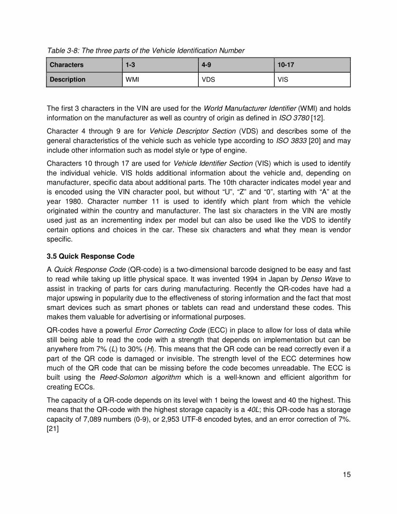
Table 5-1: Trouble code message types and their structure
Type bit 0-3 bit 4-8 Byte 2 Byte 3 Byte 4 Byte 5 Byte 6 Byte 7 Byte 8
Request type (0)
size (1) mode (03)
Single type (0)
size mode + 40 (43)
# of DTCs
data data data data
First type (1)
total size total size
mode + 40 (43)
# of DTCs
data data data data
Consecutive type (2)
sequence number
data data data data data data data
When receiving a First frame, a flow control frame is sent back to that specific ECU to instruct it to send the rest of the data. The flow control flag, separation time and block size is all set to zero to instruct the ECU to send all remaining data as fast as possible [14]. The remaining data will be sent in Consecutive frames until all trouble codes have been transmitted.
By looking at the arbitration ID of the response, the ECU number can be identified so all data can be kept separated with respect to which ECU the data came from. The trouble codes are decoded from the data according to ISO 15031-5 described in chapter 3.2.3, and the trouble codes from all ECUs are put into a long, comma separated, string.
5.3.2 VIN request
The VIN is requested on the OBD by sending a message with Mode 09 and PID 02 to the broadcast address. The ECU that contains the stored VIN will reply with a First frame and any ECU that does not contain the stored VIN will not respond to the request. The different message types and their structure are listed in table 5-2.
Table 5-2: VIN request message types and their structure
Type bit 0-3
bit 4-8 Byte 2 Byte 3 Byte 4 Byte 5 Byte 6 Byte 7 Byte 8
Request type (0)
size (2) mode (09)
PID (02)
First type (1)
total size total size
mode + 40 (49)
PID (02)
# of VINs
data data data
Consecutive type (2)
sequence number
data data data data data data data

22
When receiving the First frame, a flow control frame is sent back to that specific ECU to tell the ECU to send the rest of the message. The flow control flag, separation time and block size are all set to zero to instruct the ECU to send all remaining data as fast as possible [14]. This will be sent in Consecutive frames until the entire VIN has been transmitted.
The data bytes of the messages are hex encoded values that, using the American Standard Code for Information Interchange (ASCII) table, maps to characters that are put into a string.
5.4 Serial Communication
The RS232 serial ports on the Midrange board are here used for debugging purposes and to communicate with the GPRS module. The libraries for the STM32 processor come with a basic low-level driver for the USART peripherals of which the RS232 ports are included. The driver includes support for the required message structures and interrupts for receiving or sending messages.
The ports are initialized with settings so that communication with the GPRS module is possible. The default settings for the serial interface on the GPRS module is a baud rate of 115,200 bps, eight bits per word, no parity bits and one stop bit. [27] To send messages on the serial port the text is put into a buffer and an interrupt is generated. The interrupt handler sends and receives all data in the buffer character by character through the USART send command. Receiving data on the serial port generates an interrupt which makes the interrupt handler take care of the received message and put it into a FIFO buffer that can be read later.
5.5 GPRS
Communication with the GPRS module is made via one of the RS-232 interfaces on the Midrange board according to chapter 5.4. The AT commands (chapter 4.2.1) are sent character by character, adding newline and carriage return characters in the end to indicate to the module where a command ends. The module processes the commands after they have been received by the module and responds in the same way.
Every time a command has been sent to the GPRS module, Midrange waits for the expected reply to arrive from the module before a designated timeout value. If a reply is not received before the timeout, a unique error is generated depending on which command that failed.
5.5.1 Initialization
To initialize the GPRS module and connect to the net, a series of steps are necessary described in table 5-3. Each step corresponds to sending a specific AT command and waiting for the expected response from the GPRS module. If the reply does not arrive before the timeout threshold, an error is returned and the initialization is restarted. If the initialization has failed three times, the latest error is returned for identification and to be printed on the LCD.
First, Midrange needs to check if the GPRS module is connected and accepting commands, and then verify the Personal Identification Number (PIN) for the built in Subscriber Identity Module (SIM) card. After the SIM card has been unlocked with the correct PIN, the module starts connecting to the GPRS net. After verifying that the module is both registered and attached to the net, the GPRS context is defined by supplying the carrier Access Point Name

23
(APN), and then activated. This is where an Internet Protocol (IP) address is obtained from the carrier and entered as the IP address for the module. Lastly the module checks the signal quality to draw the correct number of signal bars to the LCD.
Table 5-3 lists the AT commands sent to the GPRS module during initialization. The underlined text means specific data that vary depending on the implementation or changes between runs.
Table 5-3: The AT command list for initialization of the GPRS module
Description AT command Expected response
Connected to module? AT OK
Test PIN AT+CPIN=pin OK
Registered to net? AT+CGREG? +CGREG: 0,1
Attached to net? AT+CGATT? +CGATT: 1
Define GPRS context AT+CGDCONT=1,"IP",”APN","0.0.0.0",0,0 OK
Activate GPRS context AT#GPRS=1 +IP: xxx.xxx.xxx.xxx
Check signal quality AT+CSQ +CSQ: quality
5.5.2 Connect to server
When connecting to the server, some configuration of the GPRS module is necessary before opening a socket. The first two AT commands in table 5-4 is used for configuration, the third is used for pinging the server, and the last command opens the socket.
Socket parameters are configured to set a socket timeout after 30 seconds of inactivity, after this time the socket should close. The firewall on the GPRS module is configured to allow connections to and from the remote server. A ping request is sent to the server, if the GPRS module gets responses from the server then it is up and running.
To finally connect to the server, a Transmission Control Protocol (TCP) socket is opened on port 80. TCP is used over UDP because it can guarantee that the transferred data remains intact and arrives in the same order it was sent. The socket is opened in online mode, which means that from that moment, every byte written to the GPRS module will be sent directly through the socket to the server instead of being interpreted as an AT command. If the socket is opened in command mode instead, the GPRS module keeps accepting and interpreting AT commands as normal. [24].

24
Table 5-4: The AT command list for connecting to the server
Description AT command Expected response
Configure socket AT#SCFG=1,1,packet size,globaltimeout,sockettimeout,data timeout
OK
Open firewall AT#FRWL=1,server adress,netmask OK
Send PING AT#PING=server_adress,port #PING: 01,server_adress,time,ttl
Open socket AT#SD=1,0,port,server adress,0,0,0 CONNECT
5.5.3 Transfer of data
Since the socket is opened in online mode, no AT commands are needed to transfer data, the data that should be transferred is just sent to the GPRS module as plain text. A HyperText Transport Protocol (HTTP) GET message is sent to the server to both deliver the VIN and trouble codes, and to request an image pattern from the server and send its compressed data in a reply. The HTTP message is shown below and contains of three lines with two empty lines in the end. Every line ends with a carriage return and newline character.
GET /?page=machine&get&cmp=hex&vin=VIN&faults=DTC HTTP/1.1 Host: obd.syntronic.com Connection: close
In the HTTP message shown above, VIN is the 17 character long VIN string and DTC is the trouble codes separated with commas (in the case of no detected faults, the &faults=DTC part is omitted from the message). The connection: close line is an extra option and tells the server to immediately close the connection after the reply has been sent to preserve server resources.
If the message was delivered correctly the first line of the response from the server will contain HTTP/1.1 200 [28]. The rest of the response contains a number of header lines that are ignored by Midrange, and the payload that is expected to contain a compressed image pattern sent by the server. The payload is decoded and turned into a bit pattern that can be printed on the display.
5.6 LCD
To prepare Midrange for the LCD, the SPI and the two data pins are initialized and the LCD circuits are turned on by setting the reset pin high. The LCD is then initialized by setting the data/command pin low and sending commands through the SPI to define the hardware settings according to table 5-5 [26].

25
Table 5-5: LCD initialization commands
Command Command (binary) Description
ADC select 10100000 Set segment driver direction select to NORMAL
Display ON/OFF 10101110 Turn display OFF
Common Output Mode (COM) select
11000000 Set COM output scanning direction to NORMAL
Select LCD bias 10100010 Set LCD voltage bias to 1/9
Power control 00101111 Turn on all power circuits
Regulator resistor select 00100110 Set voltage regulator internal resistor ratio to 6.0
Reference Voltage Select 10000001 Enable display contrast selection mode
Set Reference Voltage Register
00101000 Select contrast value 40 (0-64)
Display ON/OFF 10101111 Turn display ON
In order to draw the company logo and other images, the LCD receives bit patterns for the images that are stored in the code or supplied by the server in the case of the QR-code. An image bit pattern is essentially an array of ones and zeroes where a zero represents a white pixel and a one represents a black pixel. Numeric values are also supplied to keep track of the height and width of the images.
Text is printed in essentially the same way as images but pointers to bit patterns for every character are stored in an array. Other arrays keep track of the width and size of every character. A wrapper function is made to print strings, that automatically takes care of printing the characters to the screen and move the draw area after every character according to the size of the character that was printed.
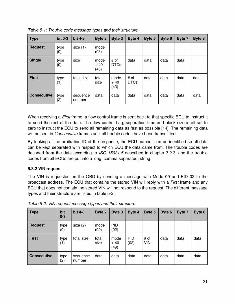
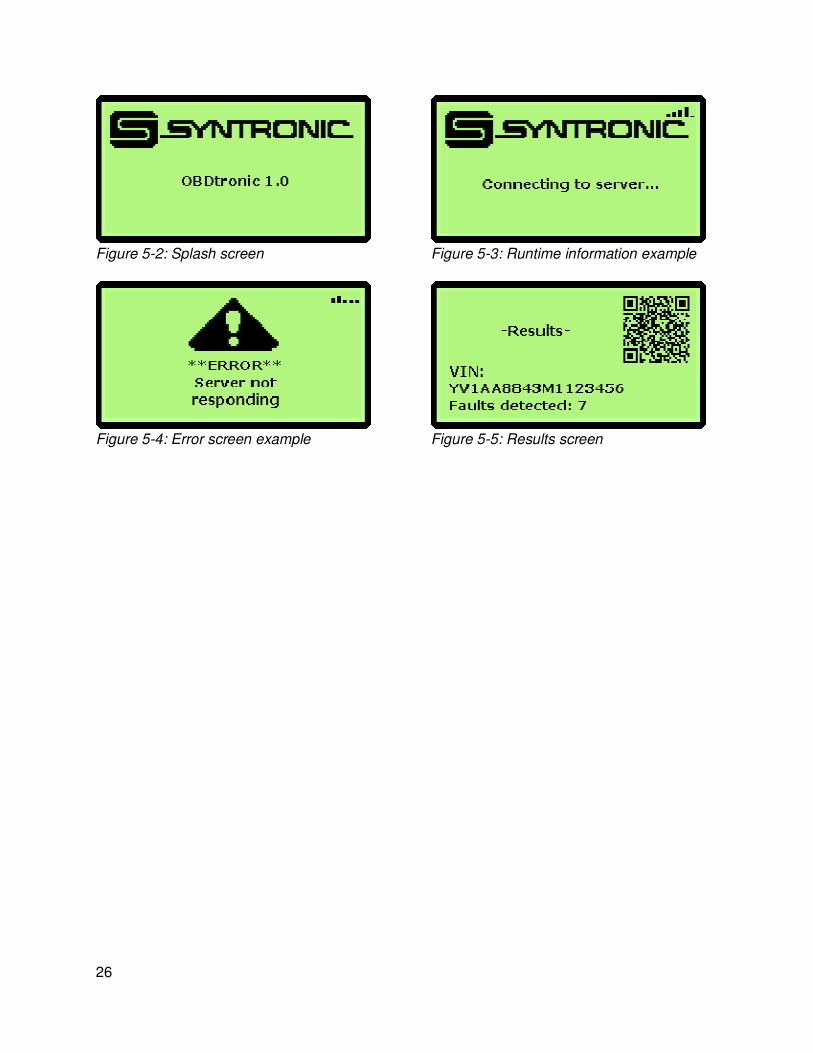
The Graphical User Interface (GUI) consists of a series of screens that displays runtime information as well as the company logo and signal strength bars. The result screen shows the current VIN, the number of faults found, and the QR-code containing a link to the VIN on the webpage. An error screen contains a warning triangle with descriptive text about the error that occurred. Example of the GUI is shown in figure 5-2, 5-3, 5-4 and 5-5.
26
Figure 5-2: Splash screen Figure 5-3: Runtime information example
Figure 5-4: Error screen example Figure 5-5: Results screen

27
6 Server The server consists of a database which holds all information relevant for the system and a user interface from which the user can access the information through a series of pages. External systems can insert new entries into the database through the web interface. The basic layout of the server is structured as displayed in figure 6-1, with the different pages being blue, external systems being red and the dynamic parts (database) being green.
Figure 6-1: Structure of the server
The database is designed on a MySQL Structured Query Language (SQL) server (version 5.6.12) and accessed through PHP Hypertext Preprocessor (PHP) (version 5.4.12) from HTTP on an Apache web server (version 2.4.4). Cascading Style Sheet (CSS) and HyperText Markup Language (HTML) is used for design and formatting of the web pages. PHPMyAdmin (version 4.0.4) is also used to administrate the MySQL database.

28
6.1 Database
6.1.1 Structure
Two types of database engines are used; MyISAM and InnoDB. MyISAM is an engine well suited for heavy read and low write access which is the case for the knowledge base type of databases that houses the trouble codes or other semi-static data which in this case is all but the car database. InnoDB is a well-rounded engine that is equally effective in both read and write access which is useful for the car database where info will be both read and written [29]. There are five tables present to handle the data within the web interface and database; users, car_db, faults, countries and brands as can be seen in figure 6-2.
• users holds information about the different users that have write access to the trouble codes in order to update notes and descriptions. The table consists of columns uid (user id), username, password (encrypted with salt and password using the blowfish cipher) and salt (the UNIX time hashed using the MD5 algorithm).
• car_db holds information about the different cars that have been introduced to the system either manually or via the Midrange platform. Columns in this table are vin, faults (comma-separated list of trouble codes), wmi and a last_modified timestamp.
• faults holds information about all different trouble codes encountered and some notes and small texts about them. faults consists of columns code (the trouble code), manufacturer (to which manufacturer the code applies), description_short (a short description of the fault [30]), description_long (a more descriptive text on the fault), symptoms, cause, fix, notes and last_modified.
• countries holds information that maps the wmis to manufacturing countries. The columns in this table are wmi (the first one or two characters in the WMI) and country.
• brands holds information about different manufacturers and maps the wmis to manufacturers. Columns in this table are wmi, manufacturer (short name of the manufacturer) and manufacturer_real (manufacturer’s full name).
Figure 6-2: Table structure in the database

29
6.1.2 Security
All external connections made to the database will be denied and thus the only way to access the MySQL server is to either have physical access to the server or by using the web interface. Every command sent to the MySQL server will pass through filters to avoid problems such as SQL injection attacks or simply faulty requests. These filters consists of adding escape sequences to special characters (NUL, ‘, , \, \n, \r, _, “, %, CTRL-Z) which otherwise could be used to break or execute arbitrary code in the SQL database.
6.2 Web Interface
The web interface consists of a number of files and directories to make it modular. When there is a request to a page on the server it will go through the index.php file with the GET argument page to specify which page should be loaded next. A redirect header is in place to prevent access through any other file than index.php which could yield unexpected results. Screenshots of the relevant pages that the user can access can be found in appendix B.
Users are able to register and log in in order to access the edit option of the trouble codes. The passwords are encrypted using blowfish and salted using a MD5 hash of the UNIX timestamp during the registration.
6.2.1 Machine Interface
When the machine interface receives arguments using either GET or POST it will verify that the VIN is 17 characters long and the trouble codes that follow are the correct length and comma separated, and if everything looks okay, insert or update the correct row in the database. After the data has been inserted, or updated, in the database the page creates a QR-code for a link to the search for the VIN in question. To create the QR-code, a library called PHPQRcode (version 1.1.4) is used. The QR code is sent back to Midrange to be printed on the LCD in the result screen.
In order to limit the amount of data that is sent over GPRS, the QR-code is compressed before sending it back to Midrange. The QR-code is converted into a bit pattern where every white pixel is represented by a zero and every black pixel by a one. This bit pattern is converted into the ASCII values of the bit patterns corresponding hex numbers and returned as a string to the client if the cmp variable is set to hex in the request header. Raw and ASCII compression, where each eight bits are represented directly by the ASCII equivalent, are also available but not used in this implementation since sending ASCII characters causes the GPRS module to interpret some values as newline characters which causes problems when Midrange receives data from the GPRS module.
6.2.2 Statistics
Using the format of the OBD trouble codes as defined in ISO 15031-6 [11] statistics for the frequency of faults overall, per system and per subsystem can be generated. Because each entry in the car_db database has information about the car, when cross referenced with other tables, such as brand, year data and a timestamp (last_modified) included statistics based on time and brand can be calculated.

30
The statistics (as seen in appendix B, figure B-5) are dynamically calculated upon request of the user and output as Portable Network Graphic (PNG) images. The image type PNG is used because of its lossless, efficient compression algorithm [31]. These images, along with raw data, are also saved into a Microsoft Excel (xlsx) document for easy presentation. Because these calculations are computationally expensive the images are cached and can only be refreshed once every 24 hours. The library pChart (version 2.1.3) is used to generate graphs for the images and the library PHPExcel (version 1.7.9) is used to save images and data to an excel document.

31
7 Results and discussion The system consists of the Midrange platform which is connected to a GPRS module, a display and to the OBD2 interface on a car. Midrange extracts data over CAN from the OBD system on the car and processes the data. The GPRS module transfers the data from Midrange through the internet via the web interface into the database. The user gets information from the display and uses the internet to access the web interface which fetches data from the database and shows it to the user.
7.1 System overview
A block diagram over the system components as well as the communication protocols and programming language used are shown in figure 7-1. The text between the boxes indicate the communication protocol or interface used between the components and the text in square brackets next to some of the boxes indicate what language the component is implemented in.
Figure 7-1: System overview block diagram
A photograph of the implemented system (except for the server) is shown in figure 7-2 together with numbers that indicate the different components. A list of the purchased components can be found in appendix C.

32
Figure 7-2: System overview
Component list:
1. Midrange 2. GPRS module 3. GPRS external antenna 4. LCD 5. OBD2 cable 6. Power switch 7. Power regulator 8. Capacitors 9. OBD2 to CAN converter 10. Midrange power cable 11. LCD cable
To eliminate the need for an external power supply the system takes its power from the cars battery via the power pin on the OBD connector. The car battery supplies around 12 V which works for the GPRS module but needs to be transformed down to 5 V for Midrange via a voltage regulator. The capacitors are placed according to the power regulator data sheet to protect the system from resonance current and voltage spikes.

33
7.2 Testing the system
Testing of the product was conducted, both during and after development, on both the OBD simulator and actual cars. The tests conducted were both on the functionality and the performance of the product.
7.2.1 Functionality
The functionality of the system was tested by connecting it to several different cars that used CAN as the OBD2 communication protocol and running the scan while monitoring the communication with the Kvaser Leaf Light. A commercial scan tool based on the ELM327 circuit was used to verify the results. The result of the testing is listed in table 7-1.
Table 7-1: Test table
Manufacturer Model Year CAN addressing mode
CAN bit rate ELM327 results
Midrange results
Land Rover Range Rover Evoque
2012 11-bit 500 kbps Scan OK, no faults
Scan OK, no faults
BMW 320d 2010 11-bit 500 kbps Scan OK, no faults
Scan OK, no faults
Land Rover Discovery 4
2011 29-bit 500 kbps Scan OK, no faults
Scan OK, no faults
Volvo V50 2011 29-bit 500 kbps Scan OK, no faults
Scan OK, no faults
Ford Focus 2011 11-bit 500 kbps Scan OK, no faults
Scan OK, no faults
Renault Espace 4 2008 11-bit 250 kbps Scan OK, no faults
Scan OK, no faults
The testing showed that the system works as intended and produces the same OBD scan results as the commercial products. The system also seems to work with both 11- and 29-bit addressing mode as well as both 250 and 500 kbps as baud rate. The data is sent successfully to the server and the QR-code on the result screen links to the correct page on the web server when read with a QR reader app on a smart phone. Although testing several vehicles, there were no cars available that had any trouble codes present, however this should theoretically not be a problem since the system worked perfectly with the OBD simulator and was able to obtain trouble codes and deliver them to the server without problems. A test was also conducted in order to, within reasonable boundaries; verify that the system can handle a large number of fault codes. The test was carried out with 30 concurrent trouble codes and worked without problems on either side but a normal run should never find this many codes in a single scan.

34
7.2.2 Data usage
The network traffic to and from the server is monitored and recorded with the network packet sniffer program Wireshark. The timestamps in the below tables are normalized with the timestamp of the ping request as zero.
When the OBD scan returns with no faults and this is sent to the server, 1556 Bytes are transmitted, according to table 7-2. If the scan has found faults the transmitted data is 1563 + 6 * N Bytes, where N is the number of faults (table 7-3). The overhead is quite large, out of the 1556 Bytes that are transmitted; the data that is relevant to the purpose of the transmission takes up 162 + 780 Bytes. This means that the overhead is as high as 40%. However the Bytes that are not directly needed by the server serve other purposes. 148 Bytes are used by the ping from Midrange to make sure that the server is up and operational. 466 Bytes are used in order to set up the TCP connection and make sure that the data has arrived correctly.
Table 7-2: Communication between Midrange and server without faults to report
Time (s) Source Destination Protocol Bytes Info
0.0000000
MIDRANGE SERVER ICMP 74 Echo (ping) request id=0x04c0, seq=24866/8801, ttl=111
0.0001454
SERVER MIDRANGE ICMP 74 Echo (ping) reply id=0x04c0, seq=24866/8801, ttl=128
0.6623060
MIDRANGE SERVER TCP 62 hpss-ndapi> http [SYN]
0.6624900
SERVER MIDRANGE TCP 62 http >hpss-ndapi [SYN, ACK]
0.9800160
MIDRANGE SERVER TCP 60 hpss-ndapi> http [ACK]
6.619333 MIDRANGE SERVER HTTP 162 GET /?page=machine&get&cmp=hex&vin=OZENELEKTRO123456 HTTP/1.1 Continuation or non-HTTP traffic
6.818593 SERVER MIDRANGE TCP 54 http >hpss-ndapi [ACK]
7.903146 SERVER MIDRANGE HTTP 780 HTTP/1.1 200 OK (text/html)
7.903381 SERVER MIDRANGE TCP 54 http >hpss-ndapi [FIN, ACK]
8.398527 MIDRANGE SERVER TCP 60 hpss-ndapi> http [ACK]
9.359701 MIDRANGE SERVER TCP 60 hpss-ndapi> http [FIN, ACK]
9.359754 SERVER MIDRANGE TCP 54 http >hpss-ndapi [ACK]

35
Table 7-3: Communication between Midrange and server with 7 faults to report
Time (s) Source Destination Protocol Bytes Info
0.0000000
MIDRANGE SERVER ICMP 74 Echo (ping) request id=0x05ec, seq=24705/33120, ttl=111
0.0001570
SERVER MIDRANGE ICMP 74 Echo (ping) reply id=0x05ec, seq=24705/33120, ttl=128
0.6352000
MIDRANGE SERVER TCP 62 vpac> http [SYN]
0.6353600
SERVER MIDRANGE TCP 62 http >vpac [SYN, ACK]
0.9624300
MIDRANGE SERVER TCP 60 vpac> http [ACK]
6.640370 MIDRANGE SERVER HTTP 211 GET /?page=machine&get&cmp=hex&vin=OZENELEKTRO123456&faults=P0100,P0200,P0300,U0100,B0200,C0300,P0101 HTTP/1.1 Continuation or non-HTTP traffic
6.840390 SERVER MIDRANGE TCP 54 http >vpac [ACK]
7.696590 SERVER MIDRANGE HTTP 780 HTTP/1.1 200 OK (text/html)
7.696880 SERVER MIDRANGE TCP 54 http >vpac [FIN, ACK]
8.118180 MIDRANGE SERVER TCP 60 vpac> http [ACK]
8.138760 MIDRANGE SERVER TCP 60 vpac> http [FIN, ACK]
8.138810 SERVER MIDRANGE TCP 54 http >vpac [ACK]
The data in tables 7-3 and 7-2 is example data and does not contain any retransmissions caused by a bad connection, which would increase the amount of transmitted data.
In addition to the transmitted data between Midrange and the server, there are extra bytes being sent in order to set up a connection between the GPRS module and the carriers APN. The amount of data used to do this could not be found in either the GPRS modules datasheet or from the carrier.
7.3 System limitations
ISO 15031-6 only describes the generic trouble codes and leaves some room for manufacturers to define their own codes. Not all manufacturers want to share this information so building a database with information about all trouble codes for all manufacturers is not easy. In addition to that, a trouble code specification is very generic and does not include more than a line of descriptive text. There are databases available for sale that includes manufacturer specific

36
information as well as more in-depth information about causes, symptoms and fixes for trouble codes, but this was too expensive for this project.
The VIS and VDS parts of the VIN are not easily decoded by the web server since they are manufacturer specific and the data is not always publicly shared by the manufacturer. However some companies offer paid services for decoding VINs in more detail than was useful for this project.
Using CAN as the only OBD2 communication protocol significantly reduces the number of cars that this system can communicate with as most cars on the market were manufactured prior to the change to CAN as most common protocol. There is an embedded microcontroller called ELM327 by ELM electronics that could be used to support all available OBD2 protocols [1]. The circuit is used like the GPRS module with serial communication and AT commands. This was however not an option for this project since Syntronic wanted to have the OBD communication implemented from the ground up in their development platform
7.4 Security issues
Because there are no security features in place in either OBD or CAN, as mentioned in chapter 3.3.3, many issues can arise when combining the two systems. There have been numerous successful attempts in which researchers have been able to gain access to or disrupt key protected areas of a vehicle rendering it unsafe for normal operations. One example of this is when researchers at the universities of Washington and California managed to gain full access to the internal CAN through the OBD interface, using a computer and custom software designed for attacking the system [17]. This allowed them not only to inject malicious or erroneous code into the network but also to reflash both the ECM and the ECUs making it possible to disable (or enable) key systems of the car, for example turning off the engine or disabling the brakes.
The user of the car relies on the ECUs to have working software, and notifying him in case of an error, in order to deem the vehicle safe for usage. While these kinds of attacks are possible using the OBD interface they can also be used from other entry points in the car, such as the telematics system or the GPS, making it a problem of the internal car system rather than the OBD interface.
There is certain personal information, such as location or identification data, available on the internal CAN that can be monitored by an attacker. This information could in the wrong hands compromise the privacy of the vehicle owner. But then again, this information is available either using other tools, such as a GPS tracker put on the outside of the car or using the license plate number to extract information about a car online, that can be both faster and easier to use.

37
8 Further development
8.1 Hardware
Since focus was to develop a working prototype, the system was developed on Midrange which is a development platform that has more peripherals and is much larger than needed for a final product. If this system were to be developed further into an end-user product it could be reduced in size and encapsulated in a casing. The main reduction in size would come from moving from the development platform and creating a custom chip with only the necessary features and components. Some components can also be reduced in size, for example the GPRS modules embedded counterpart is smaller than the terminal block used in development. An example of how this product could look like is shown in figure 8-1.
Figure 8-1: A mockup drawing of the final product
8.2 Firmware
CAN is the only OBD2 communication protocol that was implemented due to time constraints and the fact that most manufacturers have chosen to implement it as their choice of communication protocol following the legislation in the U.S. that states that all cars sold in the U.S. after 2008 must use CAN. However if this product were to be developed further, all available OBD2 communication protocols could be implemented to provide compatibility with older cars. The upper layers of the OBD communication such as the modes of operation, PIDs and trouble codes still works in the same way independent on which protocol is used so much of the present OBD related code would be usable or easily adapted when implementing more protocols.

38
8.3 Web interface and database
There are numerous ways to increase the width of the community that is to be around this service. One easy way is to add a bulletin board (forum) where users can discuss changes and fixes as well as tips and advices. This would need to be structured in a way that makes it easy for the user to find the correct trouble code and the discussions that apply. Another way of doing this would be to create a wiki page and add information about each fault as well as cars and/or manufacturers. This way, everyone (authorized) can add or change information while still abiding the fixed structure. Using a wiki tool would also enable quick access to version history as well as user information on changes made to the database.
A subscription to an external service for trouble code information to obtain manufacturer specific tips and fixes would help to keep the information in the database up to date with the manufacturer's specifications.
Further development of the web interface would benefit from extended user interaction and feedback to increase usability as well as adding features that are not yet thought of. The security that is present is not by any means all the security one would want but more of a minimum requirement.
The database setup is not optimized for a larger user base and should be split into several tables as well as servers. Caching could, and should, be used to offload the reading operations of the tables. There should preferably also be a backup service, separated from the website files that won’t be updated very frequently, in place to secure the data in case of malfunctions or user errors.

39
References [1] Elm Electronics - OBD ICs - ELM327. Elm Electronics, 2013 [viewed at 2013-11-22]. Available from http://www.elmelectronics.com/obdic.html#ELM327
[2] ARM-USB-OCD-H. Olimex, 2013 [viewed at 2013-08-20]. Available from https://www.olimex.com/Products/ARM/JTAG/ARM-USB-OCD-H/
[3] EOBD & OBDII ECU simulators. Özen Elektronik, 2013 [viewed at 2013-08-20] Available from http://www.ozenelektronik.com/?s=products2&group=eobd-obdii-ecu-simulators
[4] Kvaser Leaf Light HS OBDII. Kvaser AB, 2013 [viewed at 2013-11-22]. Available from http://www.kvaser.com/datasheets/kvaser_datasheet.php?ean=73-30130-00402-3
[5] CMSIS - Cortex Microcontroller Software Interface Standard. ARM Ltd., 2013 [viewed at 2013-09-10]. Available from http://www.arm.com/products/processors/cortex-m/cortex-microcontroller-software-interface-standard.php
[6] Why RTOS and What is RTOS?. Real Time Engineers Ltd., 2013 [viewed at 2013-08-27]. Available from http://www.freertos.org/about-RTOS.html
[7] On Board Diagnostics (OBD) | US EPA. U.S. Environmental Protection Agency, 2013 [viewed at 2013-11-22]. Available from http://www.epa.gov/obd/
[8] EUR-Lex - 31998L0069 - EN. European Parliament, 1998 [viewed at 2013-11-22]. Available from http://eur-lex.europa.eu/LexUriServ/LexUriServ.do?uri=CELEX:31998L0069:EN:HTML
[9] Road vehicles -- Communication between vehicle and external equipment for emissions-related diagnostics -- Part 3: Diagnostic connector and related electrical circuits, specification and use. ISO 15031-3:2004. Geneva, Switzerland : ISO.
[10] Road vehicles -- Communication between vehicle and external equipment for emissions-related diagnostics -- Part 5: Emissions-related diagnostic services. ISO 15031-5:2011. Geneva, Switzerland : ISO.
[11] Road vehicles -- Communication between vehicle and external equipment for emissions-related diagnostics -- Part 6: Diagnostic trouble code definitions. ISO 15031-6:2010. Geneva, Switzerland : ISO.
[12] Environmental Protection Agency (EPA). Control of Air Pollution From New Motor Vehicles and New Motor Vehicle Engines; Modification of Federal On-Board Diagnostic Regulations for: Light-Duty Vehicles, Light-Duty Trucks, Medium Duty Passenger Vehicles, Complete Heavy Duty Vehicles and Engines Intended for Use in Heavy Duty Vehicles Weighing 14,000 Pounds GVWR or Less. Federal Register [online]. United States Environmental Protection Agency. 2005-12-20, 70 (243), 75403-75411 [viewed at 2013-11-22]. Available from: fr20de05-15.
[13] Road vehicles -- Controller area network (CAN) -- Part 1: Data link layer and physical signaling. ISO 11898-1:2003. Geneva, Switzerland : ISO.
[14] Road vehicles -- Diagnostic communication over Controller Area Network (DoCAN) -- Part 4: Requirements for emissions-related systems. ISO 15765-4:2011. Geneva, Switzerland : ISO.
[15] Class B Data Communication Network Messages - Detailed Header Formats and Physical Address Assignments. SAE J2178-1:2011. Pennsylvania, United States of America : SAE.
[16] Road vehicles -- Diagnostic communication over Controller Area Network (DoCAN) -- Part 2: Transport protocol and network layer services. ISO 15765-2:2011. Geneva, Switzerland : ISO.

40
[17] Center for Automotive Embedded Systems Security. Experimental Security Analysis of a Modern Automobile. In: The Institute of Electrical and Electronics Engineers, Inc. 2010 IEEE Symposium on Security and Privacy (SP). 2010. Oakland, CA, USA: IEEE, 2010, 447-462.
[18] Road vehicles -- Vehicle identification number (VIN) -- Content and structure. ISO 3779:2009. Geneva, Switzerland : ISO.
[19] Road vehicles -- World manufacturer identifier (WMI) code. ISO 3780:2009. Geneva, Switzerland : ISO.
[20] Road vehicles -- Types -- Terms and definitions. ISO 3833:1977. Geneva, Switzerland : ISO.
[21] QR Code Essentials. DENSO ADC, 2011 [viewed at 2013-09-20]. Available from: http://www.nacs.org/LinkClick.aspx?fileticket=D1FpVAvvJuo%3D&tabid=1426&mid=4802
[22] GSM/GPRS modules and terminals | Telit Wireless Solutions. Telit Communications, 2013 [viewed at 2013-09-23]. Available from: http://www.telit.com/en/products.php
[23] 3rd Generation Partnership Project; Technical Specification Group Terminals; AT command set for GSM Mobile Equipment (ME). 3GPP TS 07.070:2003. Valbonne, France.
[24] Telit AT Commands Reference Guide. Telit Communications, 2011 [viewed at 2013-09-02]. Available from: www.telit.com/module/infopool/download.php?id=542
[25] SPI Block Guide. Motorola Inc, 2003 [viewed at 2013-08-27]. Available from: http://www.ee.nmt.edu/~teare/ee308l/datasheets/S12SPIV3.pdf
[26] LCM Specification. Shenzhen Vatronix Technology CO., LTD., 2010 [viewed at 2013-09-02]. Available from: http://www.adafruit.com/datasheets/TG12864H3-05A%20EN_V1.0.pdf
[27] GT864-QUAD / PY Terminal Product Description. Telit Communications, 2011 [viewed at 2013-11-23]. Available from: http://www.telit.com/module/infopool/download.php?id=555
[28] Hypertext Transfer Protocol -- HTTP/1.1. RFC 2616:1999. Reston, United States of America, The Internet Society.
[29] Chapter 14. Storage Engines. Oracle, 2013 [viewed at 2013-08-27]. Available from: http://dev.mysql.com/doc/refman/5.6/en/storage-engines.html
[30] OBD-II (Check Engine Light) Trouble Codes. OBD-Codes.com, 2013 [viewed at 2013-08-20]. Available from: http://www.obd-codes.com/trouble_codes/
[31] PNG: The Definitive Guide - Chapter 9. Compression and Filtering. Greg Roelofs, 2003 [viewed at 2013-10-29]. Available from: http://www.libpng.org/pub/png/book/chapter09.html

41
APPENDIX A: Flowcharts
Figure A-1: OBD initialization flowchart

42
Figure A-2: Get OBD reply flowchart

43
Figure A-3: GPRS initialization flowchart

44
Figure A-4: VIN request flowchart

45
Figure A-5: Fault code request flowchart

46
Figure A-6: Server connection flowchart

47
Figure A-7: GPRS data transfer flowchart

48
APPENDIX B: Web interface screenshots
Figure B-1: Home page

49
Figure B-2: Information about a specific VIN

50
Figure B-3: Trouble code history for a specific VIN

51
Figure B-4: Information about a specific fault code

52
Figure B-5: Global statistics about trouble codes

53
APPENDIX C: Component list 2x 33 µF Capacitors - https://www.elfa.se/elfa3~se_sv/elfa/init.do?item=65-445-89 1x RJ12 Plugs - https://www.elfa.se/elfa3~se_sv/elfa/init.do?item=42-695-51 1x Voltage Regulator - https://www.elfa.se/elfa3~se_sv/elfa/init.do?item=73-286-55 1x Power switch - https://www.elfa.se/elfa3~se_sv/elfa/init.do?item=35-222-08 1x FME Antenna - https://www.elfa.se/elfa3~se_sv/elfa/init.do?item=78-401-71 1x GSM Module - https://www.elfa.se/elfa3~se_sv/elfa/init.do?item=10-492-37 1x 100 Ohm Resistor - https://www.elfa.se/elfa3~se_sv/elfa/init.do?item=60-502-20 2x DB9 Connectors - http://www.kjell.com/sortiment/dator-kringutrustning/datorkomponenter/kontakter/db9-hane-terminalblock-p68850 1x Graphic ST7565 Positive LCD (128x64) with RGB backlight - http://www.adafruit.com/products/250 1x OBD Simulator (mOByDic 1610) - http://www.ozenelektronik.com/?s=products2&group=eobd-obdii-ecu-simulators 1x OBD-to-CAN cable (mOByDic 2000) - http://www.ozenelektronik.com/?s=products5&group=obd-accessories