DESIGN OF AN AUTONOMOUS GROUND VEHICLE BY THE … · THE 2014 INTELLIGENT GROUND VEHICLE...
16
IGVC2014JIM DESIGN OF AN AUTONOMOUS GROUND VEHICLE BY THE UNIVERSITY OF WEST FLORIDA UNMANNED SYSTEMS LAB FOR THE 2014 INTELLIGENT GROUND VEHICLE COMPETITION University of West Florida Department of Electrical and Computer Engineering EEL4930 Unmanned Systems Madison Fortenberry, Duncan Calvert, Kevin Van Landingham Dr. Xiaojun Geng ([email protected]) INTRODUCTION The purpose of the project is to design an autonomous ground vehicle capable of navigating within the provided outdoor obstacle course. The robot must complete the course within the prescribed time while maintaining a minimum of speed of 1 mph over a designated section and a maximum speed limit of 10 mph over the entire course. The robot must avoid all obstacles, while remaining within the marked lane and guide flags. The Intelligent Ground Vehicle Competition (IGVC) is located at Oakland University in Rochester, Michigan. ELECTRICAL SYSTEM The electrical system is comprised of a network of devices including sensors, processors, and actuators. The UGV will consist of several design layers including a power system, a central processor, an emergency halt module and various sensors used for localization. The sensors on board will include cameras, an inertial measurement unit, a global positioning module (GPS), quadrature encoders, ultrasonic ranging sensors, and a 2dimensional laser rangefinder. The block diagram for all of the major components in the design are shown in Figure 1. 1
Transcript of DESIGN OF AN AUTONOMOUS GROUND VEHICLE BY THE … · THE 2014 INTELLIGENT GROUND VEHICLE...

IGVC2014JIM DESIGN OF AN AUTONOMOUS GROUND VEHICLE BY THE
UNIVERSITY OF WEST FLORIDA UNMANNED SYSTEMS LAB FOR THE 2014 INTELLIGENT GROUND VEHICLE COMPETITION
University of West Florida
Department of Electrical and Computer Engineering EEL4930 Unmanned Systems
Madison Fortenberry, Duncan Calvert, Kevin Van Landingham Dr. Xiaojun Geng ([email protected])
INTRODUCTION
The purpose of the project is to design an autonomous ground vehicle capable of navigating within the provided outdoor obstacle course. The robot must complete the course within the prescribed time while maintaining a minimum of speed of 1 mph over a designated section and a maximum speed limit of 10 mph over the entire course. The robot must avoid all obstacles, while remaining within the marked lane and guide flags. The Intelligent Ground Vehicle Competition (IGVC) is located at Oakland University in Rochester, Michigan.
ELECTRICAL SYSTEM
The electrical system is comprised of a network of devices including sensors, processors, and actuators. The UGV will consist of several design layers including a power system, a central processor, an emergency halt module and various sensors used for localization. The sensors on board will include cameras, an inertial measurement unit, a global positioning module (GPS), quadrature encoders, ultrasonic ranging sensors, and a 2dimensional laser rangefinder. The block diagram for all of the major components in the design are shown in Figure 1.
1

Figure 1: Functional Block Diagram. Main Processor
The main processor will be responsible for reading the localization sensors and the mapping sensors to produce a global map which can be navigated in. It will use probability distributions with each localization sensor to produce a composite pose estimate with known error. Once localized, it will use the mapping sensors to locate objects around it and using its pose, place them on the global map. The global map will be represented in memory as a grid of squares, each with a difficulty associated with passing through it. Squares which contain barriers will have infinite difficulty, squares outside of guide flags will have a high difficulty, and squares with no known obstacles will have zero difficulty. This grid can be used in an AStar navigation algorithm to produce a path which the robot can follow through the entire course, or just to the next GPS waypoint. The main processor will also be responsible for listening to the RC Receiver and passing through manual controls upon request. This maintains a software override during normal operation.
2

Cameras
High definition cameras will be placed around the perimeter of the UGV to provide a full threehundred and sixty degree view of the surrounding area. The images captured by these cameras will be analyzed by the main processor using various computer vision algorithms. The features and objects located in the images will be used in navigation.
Laser Scanner
The laser scanner will serve as the primary mapping sensor for the robot. It will detect obstacles in the robot’s path with a higher degree of accuracy than any other sensor onboard. It will scan a 270 degree area with 1 degree angular resolution and return ranges with 1 millimeter resolution with a max range of 20 meters. This provides the main processor with accurate long range information, so it make better navigation decisions sooner, by eliminating invalid paths without having to go down them first.
Ultrasonic Sensors
Ultrasonic ranging sensors will be used to avoid collisions at times where the laser scanner and cameras cannot. Ultrasonic range finders are used because of their “bubblelike” 3dimensional forward field of sensitivity. Many ultrasonic range finders will be placed all over the UGV in order to create a fullyenclosed detection zone.
AHRS
The Absolute Heading and Reference System will combine a three axis accelerometer, a three axis gyroscope, and a three axis magnetometer to produce a single 3D pose estimate. All of these sensors together will provide a more accurate measurement than any one of them could. Most importantly, the heading estimate will have very little drift due to the magnetometer. This is because the magnetometer is based on the global north and south magnetic poles. This is very important to the performance of the robot, because it means that the data it collected at the beginning of the round will still be usable by the time it reaches the end of the round.
Batteries and Power Controller
The batteries we intend on using are 12V, 100 Ahr sealed lead acid batteries. We will be using two which will be placed in series in order to achieve a 24V system. The power from the batteries will pass through the power controller block which will consist of splitters, fuses, dcdc converters, and a power management system. In addition, there will be voltage rails for which will be utilized by components that operate at the same voltages and do not consume much power. For components that consume lots of power (i.e. motors, servos, and our main computer) will have a dedicated dcdc converter.
3

Encoders
Quadrature encoders will be used to provide an accurate measurement of wheel travel. Each wheel will have a quadrature encoder attached to a board that will keep track of the position of each wheel. The encoder control board will be connected to the main processor.
GPS
The objective of the competition is to navigate to 8 GPS waypoints, so GPS will be critical to winning the competition. The GPS pose will be combined with every other pose estimate to negate the built in error of 5 meters. This will make sure that the robot has an accurate measurement that doesn’t jump or drift throughout the round.
Motors
The UGV will be using four 24V, 400W, 2600 RPM electric scooter motors. These motors are rated at 22A each and weigh about 6lbs each. These specifications are what we expect since we wanted to make the design as rugged and reliable as possible. The motors will be capable of maneuvering effectively on all terrains expected at competition. Also, these motors will be capable of propelling our robot’s weight and the 20lb payload that is required during navigation at the competition.
Motor and Servo Controller
The motor controllers serve as the only way for the robot to control the motors in an effective way because of the nature of dc brushed motors. Essentially, our motor controllers will work just as our servo controller will. It will accept PWM signals that will each be used to control the speed and direction of each motor or servo. These signals will be sent from our main processor board.
Wireless EStop and Cutoff
At competition our robot will be required to have a mechanical emergency stop as well as a wireless emergency stop. The mechanical estop will be as simple as a 1 inch diameter state saving button that is red in color which complies with the rule book for the competition. However, the wireless estop will require an independent wireless transmitter module and receiver module that will have access and control over the cutoff switch which allows the power to flow to the motors. This cutoff switch will most likely be a digitally controlled relay.
RC Receiver
The remote control (RC) receiver will be in direct communication with an RC transmitter held by a human operator. The operator will be able to switch between RC and autonomous mode. In RC mode, the robot will respond directly to the user’s input on the transmitter. In autonomous mode, the
4

robot will begin navigating to the specified GPS waypoint. If no GPS waypoint is specified, remain stationary.
SOFTWARE STRATEGY
Our software strategy is to distribute computation to several task specific processors which will communicate with a highlevel main processor. The software flow charts for the main processor and the camera processors are shown below in Figures 3 and 4. Each flow chart describes the algorithm that will run on the respective processor.
5

Figure 2. Flow chart for the main processor.
6

Figure 3. Flow Chart for Camera Processors.
COMPUTERS
We will use two different platforms for our primary computation, the Arduino Due and the Raspberry Pi. The Arduino Due is used for timecritical and heavy I/O applications. The Raspberry Pi is used for graphics processing and networking applications.
Arduino Due
The Arduino Due is an 84 MHz microcontroller board based on the Atmel SAM3X8E ARM CortexM3 CPU. It provides real time processing and 54 digital I/O pins.
Raspberry Pi
The Raspberry Pi is a single board computer that runs at 250 MHz based on the Broadcom BCM2835 system on chip. The BCM2835 provides a camera data bus and an onchip graphics processing unit (GPU) to accelerate image processing.
7

MAPPING TECHNIQUES
Our approach to mapping uses all input sensor data in a sensor fusion algorithm. Sensor fusion assembles all input sensor data into the most likely model of the environment. The robot’s internal model of the environment is improved and expanded with time.
CAD DESIGN
We used Autodesk Inventor to design the chassis. The design begun in Fall 2013 and was completed in Spring 2014. The chassis design went through three major design iterations. The first had four wheel drive and independent suspension for each wheel. This was too expensive and difficult to build. We then removed the suspension from the design to cut costs and make construction easier. We built this version. Upon initial testing of the four wheel drive robot with no suspension, we learned the robot had difficulty turning. Our third and final design change was removing the rear two wheels and replacing them with a single caster. This threewheeled design with the front two wheels driven was constructed and tested. It satisfied all design constraints.
Figure 4. Design 1: Four wheel drive with independent suspension
8

Figure 5. Design 2: Four wheel drive with no suspension
Figure 6. Design 3 (final): Two front driven wheels with rear caster
PROBLEMS ENCOUNTERED IN DESIGN PROCESS
9
We encountered a major problem with the second chassis design iteration. Once we constructed the four wheel chassis with no suspension, we observed that is had difficulty breaking rotational friction and behaved unpredictably.
Our laser scanner was dropped by a student not involved with the project. This necessitated a $1200 repair which delayed the development of that component for more than 2 months.
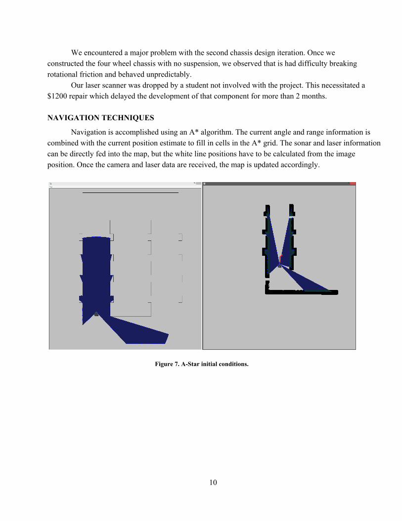
NAVIGATION TECHNIQUES
Navigation is accomplished using an A* algorithm. The current angle and range information is combined with the current position estimate to fill in cells in the A* grid. The sonar and laser information can be directly fed into the map, but the white line positions have to be calculated from the image position. Once the camera and laser data are received, the map is updated accordingly.
Figure 7. AStar initial conditions.
10

Figure 8. AStar planning path to unknown area.
Figure 9. AStar reaching the destination.
11

SYSTEM INTEGRATION PLAN
Our plan for systems integration involved the use of an onboard router/wireless access point/5port switch combo. This was used to network 3 Raspberry Pis and two Arduino Dues. This network allowed for separate development on each device with the creation of an shared API for connections.
INNOVATIONS
Simulation
Our primary innovation is the use of simulation to verify our algorithms quickly without having to buy all of the course equipment or be on site. The simulator allows us to develop and test remotely. The simulator takes the CAD model and animates it. The wheels move as they would in the real world. The simulator provides real time laser and camera sensor data taken from the simulated IGVC course. The simulated data is sent over the network to the actual robot for computation using the actual robot hardware.
Figure 10. Simulation of IGVC course obstacle detection
12

Figure 11. Map generated from simulator data
DESIGN CONSIDERATIONS
Safety
The robot is limited in hardware to a maximum speed of 10 miles/hour. It has no pointy extrusions or otherwise harmful surfaces. The robot is equipped with a red Estop button that is placed in a location that is easy to reach quickly. The Estop button disconnects power by a hardware switch to all moving components. There is an Estop remote through which the operator can stop the robot with the press of a button at any time. Durability
The aluminum used to build the frame is in a 90 degree angle shape to be as mechanically strong as possible. The wheels are 9 inches wide to distribute weight and prevent blowouts. The motors and gearing are inside the chassis and protected from weather and dirt. The wheel axes are treated to be corrosion resistant. The chassis structure is contained within plexiglass to prevent water from getting in. Reliability
13

The robot’s wheel are large and wide to prevent getting stuck in potholes or sand. The laser scanner is rated for outdoor use. The software is run through test cases to reduce bugs. All above durability items contribute to reliability. READYMADE PARTS
Our laser scanner, motors, motor controllers, microcontrollers, cameras, and computers were ready made. The power board was designed from scratch. All metal was cut by hand from raw extruded metal. All assembly was done by students. All programming and board bringup was done by students. PREDICTED PERFORMANCE
Speed
The robot with average 5 mph throughout the course.
Ramp climbing ability
The ramp will be navigated with a special case.
Reaction times
The robot will have a reaction time of 100 ms.
Battery life
The robot can operate for 2 hours.
Obstacle detection distance
The maximum detection distance of obstacles is 360 inches.
Complex obstacles
Our algorithms are designed to handle complex obstacles and areas the same way simple ones are handles. A* navigation is capable of finding any possible path. There will be a special case for the ramp.
Accuracy of arrival at navigation waypoints
The GPS unit will allow us to hit waypoints within 10 feet.
COST BREAKDOWN
Below is a cost breakdown of our autonomous ground vehicle.
14

Table 1: Part and Price Lists
Name/Link Part/Datasheet Price Each Qty
Price Total
MECHANICAL Air Ride Wheel with Standard Rim 2223T11 86.57 4 346.28QuickDisconnect Bushing 6086K213 16.10 4 64.40
Polycarbonate Sheet
http://www.homedepot.com/p/LEXAN24inx18inPolycarbonateSheetGE07/202038064#.Uo0Ju8tDvYE 19.98 3 59.94
Nylon Stand Offs http://www.mcmaster.com/#92319a495 1.4 100 140.00Nylon Screws http://www.mcmaster.com/#93135a304 5.23 2 10.46
ELECTRICAL
Lithium Ion Deep Cycle Battery Kit SBK24100 2801.23 1 2801.2
3 750 Watt Electric Motor XYD6B 109.99 4 439.96Roboteq LDC2230C Motor Controller LDC2230C 205.00 2 410.00
9 Degrees of Freedom Sensor Stick
https://www.sparkfun.com/datasheets/Sensors/Accelerometer/ADXL345.pdf http://dlnmh9ip6v2uc.cloudfront.net/datasheets/Sensors/Magneto/HMC5883LFDS.pdf https://www.sparkfun.com/datasheets/Sensors/Gyro/PSITG32000001.4.pdf 99.95 1 99.95
66 Channel LS20031 GPS 5Hz Receiver https://www.sparkfun.com/datasheets/GPS/Modules/LS20030~3_datasheet_v1.2.pdf 59.95 1 59.95
Raspberry Pi
http://www.amazon.com/RaspberryPiModelRevision512MB/dp/B009SQQF9C/ref=sr_1_2?ie=UTF8&qid=1384138755&sr=82&keywords=raspberry+pi+model+a 40.85 5 204.25
Arduino Due
http://www.amazon.com/ArduinoA000062Due/dp/B00A6C3JN2/ref=sr_1_2?ie=UTF8&qid=1384138798&sr=82&keywords=arduino+due 42.01 4 168.04
Camera
http://www.amazon.com/Logitech960000585HDWebcamC310/dp/B003LVZO8S/ref=sr_1_3?ie=UTF8&qid=1384140594&sr=83&keywords=logitech+webcam 29.39 4 117.56
30 Amp Anderson Power Poles
http://www.powerwerx.com/andersonpowerpoles/powerpolesets/30ampredblackandersonpowerpolesets.html 69.99 1 69.99
50 ft 16 gauge wire
http://www.powerwerx.com/wirecable/redblackzipcord.html?id=10631&utm_source=googleShopping&utm_medium=googleShopping&utm_campaign=googleShopping&gclid=CIS4aWL9LoCFcTm7Aod5G0AfQ 20.16 1 20.16
Power Pole Splitter http://www.powerwerx.com/powerpolepowerdistribution/ps6aainline6way.html 34.95 3 104.85
Female Headers http://www.pololu.com/product/1031 0.79 40 31.60
15

Right Angle Female Headers http://www.pololu.com/product/2712 0.63 40 25.20 Stackable Headers http://www.pololu.com/product/1035 1.76 20 35.20 Single Sided Male Headers http://www.pololu.com/product/965 0.79 10 7.90 Single Sided Right Angle Male Headers http://www.pololu.com/product/967 1.19 10 11.90 JST Male http://www.pololu.com/product/2180 0.89 20 17.80 JST Female http://www.pololu.com/product/2181 0.89 20 17.80
Ribbon Cable (15 ft)
http://www.amazon.com/RibbonCable10wire15ft/dp/B007R9SQQM/ref=sr_1_1?ie=UTF8&qid=1384978047&sr=81&keywords=ribbon+cable 9.95 2 19.90
Ribbon Cable Connectors (10 Pack)
http://www.amazon.com/GinoPositionFemaleSocketConnectors/dp/B00977HAQE/ref=pd_bxgy_pc_img_y 4.38 2 8.76
RAW MATERIAL
Acrylic Sheet
http://www.amazon.com/AcrylicSheetTransparentThicknessLength/dp/B00CPRB3C0/ref=sr_1_11?ie=UTF8&qid=1384141653&sr=811&keywords=acrylic+sheet 32.8 3 98.40
2"x2" Angle Aluminum TOTAL PRICE $5,391.48
HOURS BREAKDOWN
Duncan Calvert 400 hours +/ 50
Madison Fortenberry 500 hours +/ 75
Kevin Van Landingham 150 hours +/ 30 hours
16