Design of an Adaptive Power Oscillation Damping … of an Adaptive Power Oscillation Damping...
11
I J C T A, 9(34) 2016, pp. 295-305 © International Science Press * Assistant Professor, Dept. EEE, A.I.T.S-Rajampet, A.P, INDIA, E-mails: [email protected]; [email protected]; ** PG Student, Dept. EEE, A.I.T.S-Rajampet, A.P, INDIA, E-mail: [email protected] Design of an Adaptive Power Oscillation Damping Controller for STATCOM with Energy Storage by Fuzzy Logic Controller M. Ramesh * , P. Pamuletaiah * and Y. N. Kusuma Latha ** ABSTRACT The strategy of an adaptive power oscillation damping (POD) controller for a static synchronous compensator (STATCOM) equipped with energy storage. A modified recursive least square (RLS) algorithm technique is achieved by the signal estimation, which allows a fast, selective, and adaptive estimation of the low frequency electromechanical oscillations from nearby measured signals during power system disturbances. The proposed method is active in increasing the damping frequencies also in the case of system parameter uncertainties and at various connection points of the compensator. By using a simple two machine system model first, the analysis of the impact of active and reactive power injection into the power system will be carried out. At various connection points of the STATCOM A control diagram that optimizes active and reactive power injection will be derived using the simplified model. Small signal analysis of the dynamic performance of the proposed control plan will be carried out. The effectiveness of the proposed control method to deliver power oscillation damping regardless of the linking point of the device and in the existence of system parameter uncertainties will be verified through simulation results by using fuzzy logic controller. Here fuzzy logic is used for controlling compared to other controllers the MATLAB/Simpered Systems tool has proved that the combined system will at the same time inject maximum power and maintain the frequency. Keywords: Energy storage, low-frequency oscillation, power oscillation damping (POD), recursive least square (RLS), static synchronous compensator (STATCOM). I. INTRODUCTION In an AC power system STATIC synchronous compensator (STATCOM) is a key device for reinforcement of the stability. This scheme has been useful both at distribution level to mitigate power quality phenomena and power oscillation damping (POD) at transmission level for voltage control. By equipping the STATCOM with an energy storage connected to the dc-link of the converter although typically used for reactive power injection only, a more flexible control of the transmission system can be achieved. The wind energy and other distributed generation will cover the way for more energy storage into the power system and secondary stability improvement function is possible from the energy sources because during transient injection of active power is used temporarily. For stability enhancement function in systems where active power injection is primarily used for other drives could be attractive. Low frequency electromechanical oscillations (typically in the range of 0.2 to 2 Hz) are common in the power system and cause concern regarding secure system operation, especially in a weak transmission system. So FACTS controllers, both in shunt and series configuration, have been widely used to enhance stability of the power system. In shunt connected FACTS controllers [STATCOM and static var compensator (SVC)], first swing stability and then POD can be achieved by modulating the voltage at the point of common coupling (PCC) using reactive power injection. However, one disadvantage of the shunt
Transcript of Design of an Adaptive Power Oscillation Damping … of an Adaptive Power Oscillation Damping...

I J C T A, 9(34) 2016, pp. 295-305© International Science Press
* Assistant Professor, Dept. EEE, A.I.T.S-Rajampet, A.P, INDIA, E-mails: [email protected]; [email protected];** PG Student, Dept. EEE, A.I.T.S-Rajampet, A.P, INDIA, E-mail: [email protected]
Design of an Adaptive Power OscillationDamping Controller for STATCOM withEnergy Storage by Fuzzy Logic ControllerM. Ramesh*, P. Pamuletaiah* and Y. N. Kusuma Latha**
ABSTRACT
The strategy of an adaptive power oscillation damping (POD) controller for a static synchronous compensator(STATCOM) equipped with energy storage. A modified recursive least square (RLS) algorithm technique is achievedby the signal estimation, which allows a fast, selective, and adaptive estimation of the low frequency electromechanicaloscillations from nearby measured signals during power system disturbances. The proposed method is active inincreasing the damping frequencies also in the case of system parameter uncertainties and at various connectionpoints of the compensator. By using a simple two machine system model first, the analysis of the impact of activeand reactive power injection into the power system will be carried out. At various connection points of the STATCOMA control diagram that optimizes active and reactive power injection will be derived using the simplified model.Small signal analysis of the dynamic performance of the proposed control plan will be carried out. The effectivenessof the proposed control method to deliver power oscillation damping regardless of the linking point of the deviceand in the existence of system parameter uncertainties will be verified through simulation results by using fuzzylogic controller. Here fuzzy logic is used for controlling compared to other controllers the MATLAB/SimperedSystems tool has proved that the combined system will at the same time inject maximum power and maintain thefrequency.
Keywords: Energy storage, low-frequency oscillation, power oscillation damping (POD), recursive least square(RLS), static synchronous compensator (STATCOM).
I. INTRODUCTION
In an AC power system STATIC synchronous compensator (STATCOM) is a key device for reinforcementof the stability. This scheme has been useful both at distribution level to mitigate power quality phenomenaand power oscillation damping (POD) at transmission level for voltage control. By equipping the STATCOMwith an energy storage connected to the dc-link of the converter although typically used for reactive powerinjection only, a more flexible control of the transmission system can be achieved. The wind energy andother distributed generation will cover the way for more energy storage into the power system and secondarystability improvement function is possible from the energy sources because during transient injection ofactive power is used temporarily. For stability enhancement function in systems where active power injectionis primarily used for other drives could be attractive.
Low frequency electromechanical oscillations (typically in the range of 0.2 to 2 Hz) are common in thepower system and cause concern regarding secure system operation, especially in a weak transmissionsystem. So FACTS controllers, both in shunt and series configuration, have been widely used to enhancestability of the power system. In shunt connected FACTS controllers [STATCOM and static var compensator(SVC)], first swing stability and then POD can be achieved by modulating the voltage at the point ofcommon coupling (PCC) using reactive power injection. However, one disadvantage of the shunt

296 M. Ramesh, P. Pamuletaiah and Y. N. Kusuma Latha
configuration is that the PCC voltage must be regulated within exact limits (typically between 10% of therated voltage), and this decreases the amount of damping that can be provided by the compensator. Moreover,to modulate the PCC voltage the amount of injected reactive power needed depends on the short circuitimpedance of the grid seen at the linking point. On the other hand, injection of active power affects the PCCvoltage angle (transmission lines are effectively reactive) without varying the voltage magnitude significantly.
The control of STATCOM with energy storage (named hereafter as E-STATCOM) for power systemstability enhancement has been discussed in the literature. However, the impact of the location of the E-STATCOM on its dynamic performance is typically not treated. When active power injection is used forPOD, the location of the E-STATCOM has a significant impact on its dynamic performance. Moreover, thetypical control strategy of the device for POD available in the literature where a series of wash-out andlead-lag filter links are used to generate the control input signals. This kind of control scheme is effectiveonly at the operating point where the design of the filter links is optimized, and its speed of response islimited by the frequency of the electromechanical oscillations. A control strategy for the E STATCOMwhen used for POD will be investigated.
Figure 2: Block diagram of the control of E-STATCOM
Figure 1: Simplified two-machine system with E-STATCOM
II. SYSTEM MODELING FOR CONTROLLER DESIGN
A simplified power system model, is shown in Fig. 1, is used to study the impact of the E-STATCOM onthe power system dynamics. The investigated two area power system with each area is represented by asynchronous generator.
The synchronous generators are showed as voltage sources of constant magnitude (vg1
,vg2
) and dynamicrotor angles (�
g1, �
g2) behind a transient reactance (x1
d1, x1
d2). The transmission system consists of two
transformers represented by their equivalent leakage reactance (xt1,x
t2) and a transmission line with equivalent
reactance (xL= x
L1+x
L2). The losses in the transmission system are neglected for simpler analytical expressions.
If the mechanical damping in the generators is neglected, the complete damping for the examined system isequal to zero. Therefore, the model is appropriate to allow a conservative approach of the effect of theE-STATCOM when used for stability studies. For analysis purpose, the electrical joining point of the converteralong the transmission line is expressed by the parameter as

Design of an Adaptive Power Oscillation Damping Controller for STATCOM... 297
1
1 2( )
X
X X� �
� (1)
Where
11 1 1 1d t LX X X X� � �
12 2 2 2d t LX X X X� � �
The control of the E-STATCOM consists of an outer control loop and an inner current control loop, asshown in Fig. 2. The outer control loop, which can be an AC voltage, dc-link voltage or POD controller,sets the reference current for the inner current controller. The generic measured signal y
mdepends on the
type of outer loop control. The control algorithm is implemented in dqreference frame where a phase-locked loop (PLL) is used to track the grid voltage angle �
g from the grid voltage vector e
–g. By synchronizing
the PLL with the grid-voltage vector, the dq and modules of the injected current � �d qf fi and i control the
injected active and reactive power, respectively.
Figure 3: Equivalent circuit for two-machine system with E-STATCOM
In this paper, the outer control loop is assumed to be a POD controller. For this reason, we assume thatthe injected active and reactive powers in the steady state are zero. When designing a cascaded controller,the speed of outer control loop is typically selected is slower than the inner one to assurance stability. Thismeans that the current controller can be considered fast when designing the parameters of the outer controllerloop. Therefore, the E-STATCOM can be modeled as a controlled ideal current source, as represented inthe equivalent circuit in Fig. 3, for analysis purpose.
The level of power oscillation damping provided by the converter depends on how much the activepower output from the generators is modulated by the injected current i
f. For the system in Fig. 3, the
change in active power output from the generators due to injected active and reactive power from the E-STATCOM is calculated as in
� �1, , 2, 1 ,pg p p inj pg p p in jP P� �� � � � � � �
� �1 2 10 20
1, 2,20
sin (1 )g g g g
pg Q inj pg Qg
V VQ
E
� �� � � � ��� � �� �
� �� �
� �1 2 10 20
20
sin (1 )g g g g
in jg
V VQ
E
� �� � � � ��� � � �
� �� �(2)

298 M. Ramesh, P. Pamuletaiah and Y. N. Kusuma Latha
Where (�pg1,p
, �pg2,p
) and (�pg1,Q
, �p2,Q
) represent the change in active power from the correspondinggenerators due to injected active power (P
in j) and reactive power (Q
in j) respectively. �
p P
in j, and Q
inj are
given by
� �1 1 2 10 20
20
[(1 ) ] (1 ) sin ( )g g g g g
pg
V V V
E
�� � � �� � � �� �
The initial steady state PCC voltage magnitude Eg0
and generator rotor angles (�g10
–�g20
) correspond tothe operating point where the converter is in idle mode. A derivation to the expressions in (2) is given in theAppendix.
It can be seen from (2) and (3) that the change in active power output from the generators depends onthe location of the converter as well as on the amount of injected active and reactive power. Moreover, itcan be understood from (2) that the effective reactive power injection depends on the magnitude and directionof transmitted power from the generators.
III. POD CONTROLLER DESIGN
In this section the derivation of the POD controller from locally measured signals will be made.
(A) Derivation of Control Input Signals
The simplified two machine system is considered in Fig. 1, the active power output from each generatorshould change in proportion to the change in its speed to provide damping. From (2), the effect of thepower injected by the generator active power output highly depends on the parameter, i.e., on the locationof the E STATCOM. Using the equivalent system a control input signal that contains information on thespeed variation of the generators can be derived. When the E-STATCOM is not injecting any current, thevariation of the locally measured signals �
g, and P
tran at different E-STATCOM connection points using the
dynamic generator rotor angles �g1
and �g2
is given by
1 1 012
1 1 0 2
(1 ) sin( )tan
(1 ) cos ( )g g g
g gg g g g
V
V aV�� ��� � � �
� � � � � ��� � �� �� �� �
(4)
1 2 10 20
1 2
sin ( )g g g gtran
V VP
X X
� � ��
� (5)
From a small signal point of view and under the assumption that the PCC voltage magnitude along theline does not change significantly, the required control input signals can be derived from the PCC voltagephase and transmitted active power as
0 1 0 2(1 )gp g g p g g
d
dt
�� � � �� � � � � �� (6)
1 2 10 200 1 2
1 2
cos( )( )g g g g g
g g g
d V V
dt X X
� � ��� �� � �� ���� ��� �
(7)
The nominal system frequency is represented by where as ��g1
��g2
and represent the speed variationof the generators in p.u. The electromechanical dynamics for each generator is given by
2 gi mi gi Dmi gi
d giH T T K
dt
��� � � � � �� (8)

Design of an Adaptive Power Oscillation Damping Controller for STATCOM... 299
Where, , , ,gi mi gi giH T� �� � and KDmi
represent inertia constant, speed variation, change in input torque,
change in output torque and mechanical damping constant for the generator, respectively.
The derivative of the PCC voltage phase and transmitted active power are both dependent on the speedvariation of the generators. Moreover, the derivative of the PCC voltage phase depends on the location ofESTATCOM, through the parameter �
p, as well as the mechanical dynamics of the generators. This
information will be exploited in the POD controller design.
For the two machine system, damping is related to the variation of the speed difference between the twogenerators. From (2) and (3), it can be understood that the change in the output power due to injected activepower is maximum when the compensator is installed at the generator terminals (i.e. a=0 and a=1). Assumingequal inertia constant for the two generators, no damping is provided by injection of active power at theelectrical midpoint of the line (i.e. a=0.5 for H
g1 = H
g2) as the power output of the two generators is the same
and the net impact is zero. At this location, the derivative of PCC voltage phase is zero. This means thatscales the speed variation of the two generators depending on the location of E STATCOM and its magnitudechanges in proportion to the level of damping by active power injection. On the other hand, that the changein the output power from the generators due to injected reactive power is maximum at the electrical midpointof the line (i.e., a=0.5) and minimum at the generator terminals (i.e.,a=0 and a=1). As the changes in thepower output of the two generators are the same in magnitude and opposite in sign, between the twogenerators a signal that varies linearly with the speed variation to control reactive power injection ��g12
isan appropriate signal. This information can be obtained from the derivative of the transmitted active power
.trandp
dt
(B) Estimation of Control Input Signals
E-STATCOM locations require fast, accurate, and adaptive estimation of the critical power oscillationfrequency component. This is achieved by the use of an estimation method based on a modified RLSalgorithm. The aim of the algorithm is therefore to estimate the signal components that consist of only thelow frequency electromechanical oscillation in the measured signals �
g and P
tran. By using a PLL with
bandwidth much higher than the frequency of electromechanical oscillations, the derivative of the PCC-
voltage phase can be obtained from the change in frequency estimate of the PLL .g
d g
dt��� �� �� �
� � Therefore,
the low frequency electromechanical oscillation component can be extracted directly from the frequencyestimate of the PLL. On the other hand, the derivative of transmitted power is estimated by extracting thelow frequency electromechanical oscillation component from the measured signal, P
tran and then applying
a phase shift of �/2 to the estimated oscillation frequency component.
From the estimated control input signals �g,osc
= d�g,osc/dt
and d�tran,osc/dt
, which contain only a particular
oscillation frequency component � �* *,d qf fi i the reference injected active and reactive current components
from the E-STATCOM can be calculated to setup the POD controller as in Fig. 4. The terms KP and K
Q
represent proportional controller gains for the active and reactive current components, respectively.
To describe the estimation algorithm, an input signal y which could be either �g or P
tran, as shown in
Fig. 4, is considered. Following a power system disturbance, will consist of an average value that variesslowly and a number of low frequency oscillatory components, depending on the number of modes thatareexcited by the disturbance. For simplicity, let us assume that there exists a single oscillatory component inthe input signal.

300 M. Ramesh, P. Pamuletaiah and Y. N. Kusuma Latha
Therefore, the input signal consists of an average component Yavg
and Yosc
an oscillatory componentwhich can be modeled as
( ) ( ) ( ) cos[ ( )]avg ph oscy t Y t Y t t t� � � � � (9)
The model in (9) is rewritten using the oscillation angle ( )osc osct t� � �
From an observation matrix and measured input signal Y(t), the estimated state vector h is derivedusing the RLS algorithm in discrete time as
( ) ( 1) ( )[ ( ) ( ) ( 1)]h k h k G k y k k h k� � � � � � (10)
I is the identity matrix, the gain matrix G and covariance matrix R are calculated recursively startingwith an initial invertible matrix (0) as
( ) ( 1) ( )[ ( ) ( 1) ( )]G K R K k k R k k� � � � � � � � (11)
[ ( ) ( )] ( 1)( )
I G k k R kR k
� � ��
�(12)
With TS representing the sampling time, the steady-state bandwidth of the RLS RLS� and the estimation
error are given by
Modification in the Conventional RLS Algorithm: The selection of is a tradeoff between a good selectivityfor the estimator and its speed of response. A high forgetting factor results in low estimation speed withgood frequency selectivity.
With increasing estimation speed (decreasing), the Frequency selectivity of the algorithm reduces. Forthis reason, the conventional RLS algorithm must be modified in order to achieve fast transient estimationwithout compromising its steady state selectivity. This is achieved with theuse of variable forgetting factor as
Figure 4: Block diagram of the POD controller
Figure 5: Block diagram of the modified RLS estimator for multiple oscillation modes

Design of an Adaptive Power Oscillation Damping Controller for STATCOM... 301
described when the RLS algorithm is in steady state, its bandwidth is determined by the steady state forgettingfactor. If a rapid change is detected in the input will be modified to a smaller transient forgetting factor. Thus,by using a high pass filter with time constant will be slowly increased back to its steady state value. Besides,the performance of the estimation method depends on accurate knowledge of the oscillating frequency. Thisfrequency is dependent on the system parameters and its operating conditions. If the frequency content of theinput changes, the estimator will give rise to a phase and amplitude error in the estimated quantities.
Assuming that the input signal contains oscillatory components, (9) must be modified as
( ) 1( ) ,Navg t iy t Y Yosc i�� � � (13)
Where the oscillation mode Yosc,i (with i=1…..N) is expressed in terms of its amplitude, frequency,and phase. Thus, the POD controller in Fig. 4 can be modified accordingly to control each modeindependently. Observe that the phase shift applied for calculation of the reference currents depends on theinvestigated system and needs to be calculated for each oscillatory mode.
IV. STABILITY ANALYSIS OF SYSTEM MODEL
The mathematical model of the system in Fig. 3 is developed in this section to investigate the performanceof the POD controller using active and reactive power injection. Using the expression sin (6)–(7)
1 2[ (1 ) ]df p go p g p gi K � � �� � � � � � � (14)
Where the constant is as defined in (3). Two machine system with the E STATCOM in per unit isdeveloped as in
11 11 12 13 11
12 0 122
3 31 32 33 3
1
10
2
0 0 0
10
2
gg gm
g g go gm
g g
g
HTd
Tdt
H
� �
� �
� �
� �� �� � � �� � � � �� � � � �� �� � � �� � � �� � � �� � � � �� � � �� � �� � � �� � � �� �� � � � �� � � �� � � �� �� �
(15)
The synchronizing torque coefficients resulting from the selected operating point and the contributionof the E-STATCOM is zero. To provide positive damping, and should be negative. For this, the sign ofshould be negative and the sign of K
Q should be chosen based on the sign of.
Figure 6: Real and imaginary part of the complex conjugate poles versus position. (a) Active power injection.(b) Reactive power injection. (c) Active and reactive power injection

302 M. Ramesh, P. Pamuletaiah and Y. N. Kusuma Latha
Transmitted power from Generator 1 to Generator 2, will be positive and the sign of KQ should be
negative. For a transmitted power in the other direction, the sign of KQ should be opposite. With active
power injection only, the cross couplingterms reduce the damping as the speed variation ofthe generatorswill be opposite at the oscillatory frequency. At the mass scaled electrical midpoint of the line where, thedamping that can be provided by is zero. Therefore, the active power injected by the E-STATCOM at thislocation is set to zero by the control algorithm. When moving away from this point towards the generatorterminals, increases and at the same time the cross coupling terms decrease.
The leakage reactance of the transformers and transient impedance of the generators are 0.15p.u and0.3p.u, respectively. The movement of the poles for the system as a function of the E STATCOM locationis shown in Fig. 6. The reverse happens at either end of the generators, that a more uniform damping alongthe line is obtained by using injection of both active and reactive power.
Figure 7: Simplified two-area four machine power system
V. FUZZY LOGIC CONTROL
The Fuzzy logic control consists of set of linguistic variables. Here the PI controller is replaced with FuzzyLogic Control. The mathematical modeling is not required in FLC. FLC consists of
1. Fuzzification: Membership function values are assigned to linguistic variables. In this scaling factoris between 1 and -1.
2. Inference Method: There are several composition methods such as Max-Min and Max-Dot havebeen proposed and Min method is used.
3. Defuzzificaion: A plant requires non fuzzy values to control, so Defuzzificaion is used. The outputof FLC controls the switch in the inverter. To control these parameters they are sensed and compared withthe reference values. To obtain this the membership functions of fuzzy controller are shown in fig (7).
The set of FC rules are derived from
u=-[� E + (1-�)*C] (16)
Where � is self-adjustable factor which can regulate the whole operation. E is the error of the system,C is the change in error and u is the control variable. A large value of error E indicates that given system isnot in the balanced state.
Figure 8: Fuzzy logic Controller
Design of an Adaptive Power Oscillation Damping Controller for STATCOM... 303
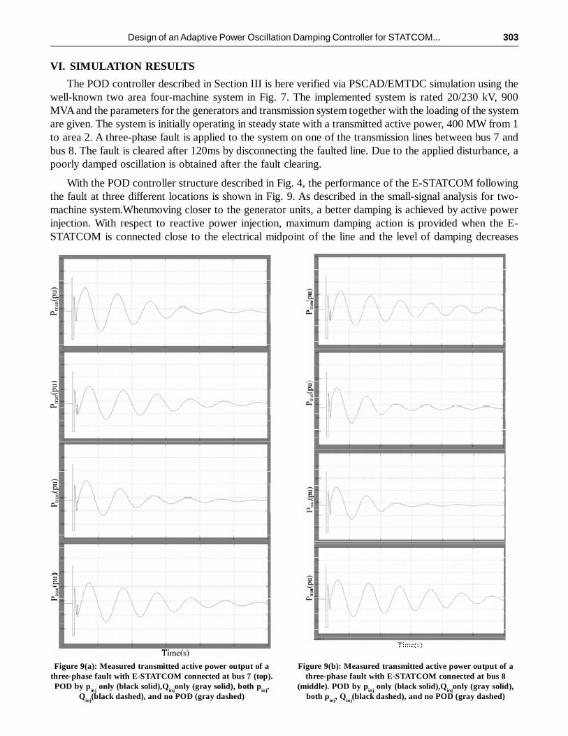
VI. SIMULATION RESULTS
The POD controller described in Section III is here verified via PSCAD/EMTDC simulation using thewell-known two area four-machine system in Fig. 7. The implemented system is rated 20/230 kV, 900MVA and the parameters for the generators and transmission system together with the loading of the systemare given. The system is initially operating in steady state with a transmitted active power, 400 MW from 1to area 2. A three-phase fault is applied to the system on one of the transmission lines between bus 7 andbus 8. The fault is cleared after 120ms by disconnecting the faulted line. Due to the applied disturbance, apoorly damped oscillation is obtained after the fault clearing.
With the POD controller structure described in Fig. 4, the performance of the E-STATCOM followingthe fault at three different locations is shown in Fig. 9. As described in the small-signal analysis for two-machine system.Whenmoving closer to the generator units, a better damping is achieved by active powerinjection. With respect to reactive power injection, maximum damping action is provided when the E-STATCOM is connected close to the electrical midpoint of the line and the level of damping decreases
Figure 9(a): Measured transmitted active power output of athree-phase fault with E-STATCOM connected at bus 7 (top).POD by p
inj only (black solid),Q
injonly (gray solid), both p
inj,
Qinj
(black dashed), and no POD (gray dashed)
Figure 9(b): Measured transmitted active power output of athree-phase fault with E-STATCOM connected at bus 8
(middle). POD by pinj
only (black solid),Qinj
only (gray solid),both p
inj, Q
inj(black dashed), and no POD (gray dashed)

304 M. Ramesh, P. Pamuletaiah and Y. N. Kusuma Latha
when moving away from it (see Fig. 9, gray solid plots). Because of a good choice of signals for controllingboth active and reactive power injection, effective power oscillation damping is provided by the E-STATCOMirrespective of its location in the line (see Fig. 9, black dashed plots).
VII. CONCLUSION
An adaptive POD controller by E-STATCOM has been developed in this paper. The MATLAB/Simperedsystems simulation shows sensible performances of this controller. Here fuzzy controller is used comparedto alternative controllers because of its accurate performance. For this, a modified RLS algorithm has beenused for estimation of the low-frequency electromechanical oscillation components from locally measuredsignals during power system disturbances. The estimator enables a fast, selective and adaptive estimationof signal components at the power oscillation frequency. The dynamic performance of the POD controllerto provide effective damping at various connection points of the E-STATCOM has been validated through
Figure 9(c): Measured transmitted active power output of three phase fault with E-STATCOM connected at bus 9 (bottom).POD by p
inj only (black solid),Q
injonly (gray solid), both p
inj, Q
inj(black dashed), and no POD (gray dashed)

Design of an Adaptive Power Oscillation Damping Controller for STATCOM... 305
simulation as well as experimental verification. The robustness of the control algorithm against systemparameter changes has also been proven through experimental tests. Furthermore, using the frequencyvariation at the E-STATCOM connection point as the input signal for the active power modulation, it hasbeen shown that active power injection is minimized at points in the power system where its impact onPOD is negligible. This results in an optimal use of the available energy source.
REFERENCES[1] N. G. Hingorani and L. Gyugyi, Understanding FACTS. Concepts and Technology of Flexible AC Transmission Systems.
NewYork,NY, USA: IEEE, 2000.
[2] G. Cao, Z. Y. Dong, Y. Wang, P. Zhang, and Y. T. Oh, “VSC based STATCOM controller for damping multi-modeoscillations,” in Proc.IEEE Power and Energy Soc. General Meeting—Conversion and Delivery of Electrical Energy inthe 21st Century, Jul. 2008, pp. 1–8.
[3] M. Zarghami and M. L. Crow, “Damping inter-area oscillations in power systems by STATCOMs,” in Proc. 40th NorthAmer. PowerSymp., Sep. 2008, pp. 1–6.
[4] Z. Yang, C. Shen, L. Zhang,M. L. Crow, and S. Atcitty, “Integration of a statcom and battery energy storage,” IEEE Trans.Power Syst., vol. 16, no. 2, pp. 254–260, May 2001.
[5] A. Arulampalam, J. B. Ekanayake, and N. Jenkins, “Application study of a STATCOM with energy storage,” Proc. Inst.Electr. Eng.—Gener.,Transm. andDistrib., vol. 150, pp. 373–384, July 2003.
[6] N. Wade, P. Taylor, P. Lang, and J. Svensson, “Energy storage for power flow management and voltage control on an 11kV UK distributionnetwork,” Prague, Czech Republic, CIRED paper 0824, Jun. 2009.
[7] A. Adamczyk, R. Teodorescu, and P. Rodriguez, “Control of full-scale converter based wind power plants for damping oflow frequency system oscillations,” in Proc. IEEE PowerTech, Trondheim, Norway, Jun. 2011, pp. 1–7.
[8] H. Xie, “On power-system benefits, main-circuit design, control of Statcoms with energy storage,” Ph.D. dissertation,Dept. Electr. Energy Conversion, Royal Inst. Technol., Stockholm, Sweden, 2009.
[9] P. Kundur, Power System Stability and Control. New York, NY, USA: McGraw-Hill, 1994.
[10] K. Kobayashi, M. Goto, K. Wu, Y. Yokomizu, and T. Matsumura, “Power system stability improvement by energy storagetype STATCOM,” in Proc. IEEE Power Tech Conf., Bologna, Italy, Jun. 2003, vol. 2, DOI 10.1109/PTC.2003.1304302.
[11] L. Zhang and Y. Liu, “Bulk power system low frequency oscillation suppression by FACTS/ESS,” in Proc. IEEE PESPower Syst. Conf. Exp., Oct. 2004, pp. 219–226.
[12] A. Arsoy, L. Yilu, P. F. Ribeiro, and F. Wang, “Power converter and SMES in controlling power system dynamics,” inProc. Ind. Appl. Conf., Oct. 2000, vol. 4, pp. 2051–2057.
[13] M. Beza and M. Bongiorno, “A fast estimation algorithm for low-frequency oscillations in power systems,” in Proc. 14thEur. Conf. Power Electron. Appl., Sep. 2011, pp. 1–10.
[14] M. Beza, “Control of energy storage equipped shunt-connected converter for electric power system stability enhancement,”LicentiateThesis, Dept. Energy and Environment, Chalmers Univ. of Technol., Gothenburg, Sweden, 2012.
[15] L. Ängquist and M. Bongiorno, “Auto-normalizing phase-locked loop for grid-connected converters,” in Proc. IEEEEnergy Conv. Congress Expo., Sep. 2009, pp. 2957–2964.