DESIGN OF A TIEBACK ANCHOR SYSTEM OF A TIEBACK ANCHOR SYSTEM ... Three radii used in the bending...
103
Project No. LDA-1506 DESIGN OF A TIEBACK ANCHOR SYSTEM A Major Qualifying Project Report Submitted to the Faculty of the Worcester Polytechnic Institute In partial fulfillment of the requirements for the Degree of Bachelor of Science in Civil Engineering Submitted By: Kelsie Lazaro Date Submitted: July 24, 2015 Approved By: Professor Leonard D. Albano This report represents the work of a WPI undergraduate student. Submitted to the faculty as evidence of completion of a degree requirement. WPI routinely publishes these reports on its website without editorial or peer review.
Transcript of DESIGN OF A TIEBACK ANCHOR SYSTEM OF A TIEBACK ANCHOR SYSTEM ... Three radii used in the bending...
Project No. LDA-1506
DESIGN OF A TIEBACK ANCHOR SYSTEM
A Major Qualifying Project Report
Submitted to the Faculty
of the
Worcester Polytechnic Institute
In partial fulfillment of the requirements for the
Degree of Bachelor of Science in Civil Engineering
Submitted By:
Kelsie Lazaro
Date Submitted:
July 24, 2015
Approved By:
Professor Leonard D. Albano
This report represents the work of a WPI undergraduate student. Submitted to the faculty as
evidence of completion of a degree requirement. WPI routinely publishes these reports on its
website without editorial or peer review.
2
Abstract
Design analysis of multiple options for a through-bolt tieback anchor was proposed. The main
objective of the project was to design an anchor with high constructability while also cost
effective for production and sale by MIW Corporation. This objective was met through
engineering drawings and structural analyses of multiple designs, and a multi-attribute analysis
identified the most effective option. The project also included a detailed final design that met
standards imposed by the Occupational Safety and Health Administration.

3
Capstone Design
The project focuses on developing a roof tieback anchor for MIW Corporation to produce
and sell. Very few fabricators in the United States produce these items, and they are more
commonly purchased and shipped from countries such as Canada. Recently MIW considered the
possibility of selling their own within the Greater Boston area, which would be at lower cost than
the Canadian systems due to the proximity of the company to its market.
Through-bolt tieback anchors are a safe and practical anchorage solution that is used for
fall protection. They have an overall simple design which results in increased productivity for the
manufacturer. Prior to producing these systems, the president of the company, George Malatos,
wants to ensure he has a cost-effective design that complies with all related specifications. The
project focuses on fulfilling these needs.
This project consisted of four phases: investigation of a benchmark design, creation of
preliminary designs, analysis and evaluation of alternatives and selection of the best alternative,
and preparation of a detailed design. The investigation of the benchmark involved back
calculating the capacity of an existing design, creating a template that simplified the design of
alternatives later in the project. Research was found through investigation of related engineering
standards.
The first step in the creating the preliminary designs was to take into account the requests
and design ideas of the client, MIW Corporation. Research was also completed to identify
possible alternatives that could improve the design’s sustainability and efficiency. Once all the
information was compiled, five preliminary designs were generated. Different approaches were
followed to determine the best design for the needs of the company, as well as the requirements
for fall protection systems.
After the preliminary designs were defined, each alternative was analyzed and evaluated
to identify the most efficient design. The designs were analyzed for constructability,
sustainability, use flexibility, and cost efficiency. The best design was selected based on these
four attributes.
The completion of this capstone design experience included the following realistic
constraints: economic, health and safety, manufacturability, sustainability, and ethical. The cost
4
efficiency was analyzed using material take offs for each of the designs as well as considering
production time. Cost factors include the building materials, complexity of fabrication (i.e. man
hours for welding), and complexity of erecting.
Health and Safety is one the many engineering standards that were upheld throughout the
duration of the project. Many of these standards are reflected by OSHA requirements. The main
goal of the project was to design the anchor within Occupational Safety and Health Association’s
minimum design requirements for fall back systems in order to ensure safety of workers. Each
design alternative was checked to confirm that it complies with all safety regulations.
The manufacturability of each design was considered for ease of construction, given the
client’s resources. The client’s shop manager was consulted to review each of the designs to rate
the difficulty of each of the connections as well as the bend in the ¾” bent bar of each design.
Sustainability in construction has increased its importance recently. The sustainability of
the different materials used in the anchor designs were analyzed. Some factors analyzed included
the protection against corrosion, resistance to fire and overall durability. Better sustainability also
leads to lower maintenance costs.
The ASCE (American Society of Civil Engineers) Code of Ethics was also considered.
The Code of Ethics was first adopted in 1914, and is the model for professional conduct for
ASCE members. The four main principles of the Code of the Ethics assist engineers to uphold
and advance the integrity, honor, and dignity of their engineering. While designing the roof
anchor, the health, safety, and welfare of the possible users of the product were held in high
regard.

5
Professional Licensure Statement
Professional Engineering (PE) licensure enforces standards that restrict practice to
qualified individuals who have met specific qualifications through their education, work
experience, and passing exams. This ensures a high quality of engineering work. Having a PE
license shows the competence of an individual engineer. These standards are regulated by state in
the United States.
Completing the requirements to become a licensed engineer is an extensive process.
Obtaining a license is a high distinction that sets some engineers above the rest. It is not a
requirement to become a licensed engineer; a non-certified engineer can work under supervision
of one with a license. However, licensed engineers have access to more favorable employment
opportunities, including business ownership. The licensing requirements begin with a completion
of a bachelor’s degree at an ABET-accredited engineering program. The next step is passing the
Fundamentals of Engineering (FE) Exam to become an Engineer-in-Training (EIT). After a
minimum of four years of acceptable work experience as an EIT under the supervision of a PE,
the more specific Professional Engineering Exam can be taken. Passing the PE Exam along with
the submission of an experience portfolio are the final steps to obtain the PE License.
Receiving PE licensure is a symbol of high qualification in the engineering industry. The
achievement of becoming a PE means competence and safety to clients and the public, ability to
take on greater responsibilities to an employer, and respect among co-workers and colleagues.
Along with the ability to stamp and seal drawings, move up in their career, and perform
consulting service, there are many responsibilities that licensed engineers have to follow, such as
awareness of legal requirements, ethical conduct, continued education, and participation in
professional organizations. Licensed engineers combine their skills to create high quality projects
while upholding the health and safety of the public as one of their main responsibilities.
This project involves the analysis of roof anchor design alternatives. Once the design is
chosen and completed, it will need to be approved by a professional engineer (PE). Achieving
PE approval ensures the design is in compliance with all regulations. This maintains safety and
fulfills the Massachusetts General Law that engineering work may be performed only by a
Professional Engineer or under the direct supervision of a PE.
6
Acknowledgements
I would like to acknowledge a number of people. Without their contributions, I would not have
been able to accomplish the goals of this project. These people include:
First of all, my advisor, Professor Leonard Albano for his advice, patience and constant
support throughout the project.
George Malatos, owner of MIW Corporation, for allowing me the opportunity to
complete my MQP with his company and gain valuable professional experience.
Mike Walker, shop supervisor at MIW Corporation, for educating me about the
fabrication process in steel construction.
Jake Hughes, civil engineering teaching assistant at WPI, for his patience and assistance
with the design checks.

7
Table of Contents
DESIGN OF A TIEBACK ANCHOR SYSTEM ........................................................................... 1
Abstract ....................................................................................................................................... 2
Capstone Design .......................................................................................................................... 3
Professional Licensure Statement ............................................................................................... 5
Acknowledgements ..................................................................................................................... 6
List of Figures ............................................................................................................................. 9
List of Tables ............................................................................................................................. 10
Chapter One: Introduction ......................................................................................................... 11
Chapter Two: Background ........................................................................................................ 13
Fall Back Protection Systems ................................................................................................ 13
Governing Standards ............................................................................................................. 14
Structural Design ................................................................................................................... 14
Chapter Three: Methodology .................................................................................................... 21
Preparation of Benchmark Calculations ................................................................................ 21
Creation of Design Alternatives ............................................................................................ 22
Analysis of Design Alternatives ............................................................................................ 24
Development of Detailed Design .......................................................................................... 25
Chapter Four: Preparation of Benchmark Calculations ............................................................ 27
Chapter Five: Creation of Alternative Designs ......................................................................... 35
Chapter Six: Analysis of Alternatives ....................................................................................... 44
Evaluation Criteria ................................................................................................................. 44
Weighted Evaluation ............................................................................................................. 45
Evaluation of Alternatives ..................................................................................................... 46
Chapter Seven: Conclusions and Recommendations ................................................................ 48
8
Summary ................................................................................................................................ 48
Conclusion ............................................................................................................................. 52
References ................................................................................................................................. 53
Appendices ................................................................................................................................ 55
Appendices A: Project Proposal ........................................................................................... 55
Appendix B: AutoCAD Drawing of Benchmark Design ...................................................... 66
Appendix C: Hand Calculations of Benchmark Design ........................................................ 67
Appendix D: RISA 3D Results of Forces in Bent Bar in Benchmark Design ...................... 71
Appendix E: Preliminary Sketches ........................................................................................ 72
Appendix F: Hand Calculations of Design #2 ....................................................................... 73
Appendix G: Hand Calculations of Design #3 ...................................................................... 77
Appendix H: Hand Calculations of Design #4 ...................................................................... 83
Appendix I: Hand Calculations of Design #5 ........................................................................ 86
Appendix J: Stress Values in Bent Bar for Design #2 ........................................................... 91
Appendix K: Stress Values in Bent Bar for Design #3 ......................................................... 91
Appendix L: Stress Values in Bent Bar for Design #4 .......................................................... 92
Appendix M: Stress Values in Bent Bar for Design #5 ......................................................... 92
Appendix N: AutoCAD Drawing of Design #2 .................................................................... 93
Appendix O: AutoCAD Drawing of Design #3 .................................................................... 93
Appendix P: AutoCAD Drawing of Design #4 ..................................................................... 94
Appendix Q: AutoCAD Drawing of Design #5 .................................................................... 94
Appendix R: Atlantic Stainless Steel Estimate...................................................................... 95
Appendix S: AutoCAD Drawings of Recommended Design ............................................... 96
Appendix T: Hand Calculations of Recommended Design ................................................... 97
Appendix U: Stress Values in Bent Bar for Recommended Design ................................... 103
9
List of Figures
Figure 1: Roof tie-back anchor ..................................................................................................... 13
Figure 2: Tie-down Anchor designed by Olsen Engineers ........................................................... 15
Figure 3: Three radii used in the bending stress calculation of a curved beam ............................ 17
Figure 4: RISA3D drawing of top bent bar .................................................................................. 18
Figure 5: Benchmark Design Roof Tie-Down Anchor ................................................................. 27
Figure 6: Force Diagrams of Virtual Work of a Half structure with Anti-Symmetric Boundary
Condition....................................................................................................................................... 30
Figure 7: Final Results of Shear and Reaction Forces .................................................................. 30
Figure 8: Joint reaction results from computer analysis ............................................................... 31
Figure 9: Bent Bar Connection with a Cap Plate .......................................................................... 35
Figure 10: Bent Bar Connection without a Cap Plate ................................................................... 35
Figure 11: Drawing of the typical baseplate design and bolt placement ...................................... 37
Figure 12: Recommended Design of Roof Tie-Down Anchor ..................................................... 48
Figure 13: Recommended Design of Roof Tie-Down Anchor ..................................................... 49
10
List of Tables
Table 1: Ultimate and Yield Strength of Carbon vs. Stainless Steel , values based on AISC Table
2-4 ................................................................................................................................................. 16
Table 2: Table of Resistance Factors Used in LRFD Calculations .............................................. 20
Table 3: Brief explanation of the four phases of the project ......................................................... 21
Table 4: Brief design summary of alternatives ............................................................................. 24
Table 5: Stresses Acting on Round Bent Bar in Benchmark Design, based on applied 5000 lb
force .............................................................................................................................................. 29
Table 6: Table of stress values and the corresponding limits calculated for the benchmark design
....................................................................................................................................................... 33
Table 7: Design drawings and summaries of the five preliminary designs .................................. 39
Table 8: The design summary and stress values of the five preliminary designs ......................... 41
Table 9: Cost of materials used in anchor designs ........................................................................ 45
Table 10: Scores of the three attributes from comparison and resulting weight factors ............... 46
Table 11: The results of the five designs efficiency in sustainability, constructability, use
flexibility and cost......................................................................................................................... 47
Table 12: The final scores of the five preliminary designs ........................................................... 47
Table 13: Table of stress values and the corresponding limits calculated for the final design..... 50
Table 14: Final scores including the recommended design .......................................................... 51

11
Chapter One: Introduction
MIW Corporation has been fabricating and installing miscellaneous and ornamental
metal since 1972. Originally concentrating on ornamental fences, gates, and rails, the company
began to flourish with a number of projects in the Back Bay and Greater Boston Area in the
1970’s.
In 1980, MIW began fabricating and installing more complex miscellaneous and
ornamental steel after purchasing a small fabricating shop in Roslindale, MA. The company also
started producing small to mid-size structural steel projects in 1990. This allowed MIW to
expand their connections within the Boston Market and work on more complex projects.
In 2005, MIW became a member of the National Ornamental & Miscellaneous Metals
Association (NOMMA) and the American Welding Society (AWS). These two memberships
have allowed MIW to strengthen their networks, and gain numerous resources within their
industry.
After purchasing a larger fabrication shop in Fall River, MA in 2007, the company has
increased the number and types of equipment for the production of both miscellaneous and
structural steel. Due to this expansion, the company also fabricates both stainless steel and
aluminum products.
MIW became certified in steel fabrication by the American Institute of Steel Construction
(AISC) in 2014. Participating in AISC’s certification program shows the respect and safety MIW
holds for its products and employees. Companies achieve a higher quality and value when
certified by AISC.
MIW Corporation continues to look for ways to extend its market. One product they
would like to begin producing is tieback anchors. Through-bolt tieback anchors are a permanent
anchorage solution that is both safe and practical. They are used for fall protection and a wide
range of suspended access uses. Some of these applications include window cleaning and
exterior building maintenance.

12
The purpose of this project is to design an effective roof tieback system that meets the
requirements of the Occupational Safety and Health Administration (OSHA) and The American
National Standards Institute (ANSI) while still cost effective.
This report consists of seven chapters. Following this introduction, Chapter Two includes
a background about fall back protection systems, the governing factors and design approaches
taken in the design process. The third chapter provides a brief overview about the methodology
of the project. Chapter Four explains the calculations and design process of the first, benchmark
design. The fifth chapter includes each of the variations used in the alternatives and presents
each of the designs. Chapter Six discusses the analysis of the alternative designs and explains the
scoring processes used to give a value to the designs. The last chapter presents the final design
and the future recommendations for the MIW Corporation.

13
Chapter Two: Background
The main goal of this project is to design a roof tieback system for MIW to fabricate, sell,
and install. The goal was accomplished using methods to create an efficient alternative. This
section addresses background information used to complete the project.
Fall Back Protection Systems
Through-bolt tieback anchors are a permanent anchorage solution that is both safe and
practical. They are used for fall protection and a wide range of suspended access uses (Flexible
Lifeline Systems, n.d.). Some of these applications include window cleaning and exterior
building maintenance.
Figure 1: Roof tie-back anchor
The figure above is an example of a tie back anchor. It consists of a base plate, which is
bolted to a beam on the roof; a metal pipe which has a tall enough height that it extends past roof
decking, keeping the attachment point accessible after the roof is complete; and a top bent round
bar, which a worker’s lifeline is clipped to. OSHA requires the use of fall back protection when
workers are doing specific tasks or suspended from minimum heights. Some of these tasks
include exterior maintenance of buildings or window cleaning. The roof anchor provides safety
protection from falls by clipping a rope descent system to the bent bar on the top of the
permanent roof anchor (Selected OSHA Fall, 2015).
14
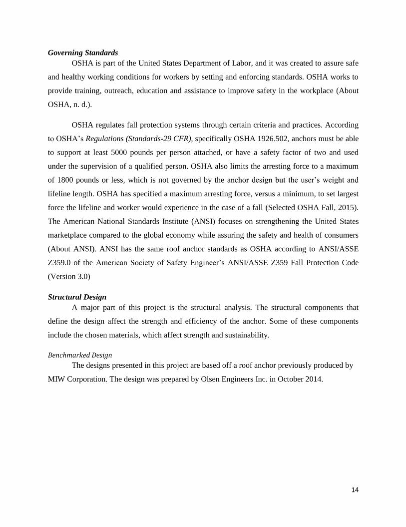
Governing Standards
OSHA is part of the United States Department of Labor, and it was created to assure safe
and healthy working conditions for workers by setting and enforcing standards. OSHA works to
provide training, outreach, education and assistance to improve safety in the workplace (About
OSHA, n. d.).
OSHA regulates fall protection systems through certain criteria and practices. According
to OSHA’s Regulations (Standards-29 CFR), specifically OSHA 1926.502, anchors must be able
to support at least 5000 pounds per person attached, or have a safety factor of two and used
under the supervision of a qualified person. OSHA also limits the arresting force to a maximum
of 1800 pounds or less, which is not governed by the anchor design but the user’s weight and
lifeline length. OSHA has specified a maximum arresting force, versus a minimum, to set largest
force the lifeline and worker would experience in the case of a fall (Selected OSHA Fall, 2015).
The American National Standards Institute (ANSI) focuses on strengthening the United States
marketplace compared to the global economy while assuring the safety and health of consumers
(About ANSI). ANSI has the same roof anchor standards as OSHA according to ANSI/ASSE
Z359.0 of the American Society of Safety Engineer’s ANSI/ASSE Z359 Fall Protection Code
(Version 3.0)
Structural Design
A major part of this project is the structural analysis. The structural components that
define the design affect the strength and efficiency of the anchor. Some of these components
include the chosen materials, which affect strength and sustainability.
Benchmarked Design
The designs presented in this project are based off a roof anchor previously produced by
MIW Corporation. The design was prepared by Olsen Engineers Inc. in October 2014.
15
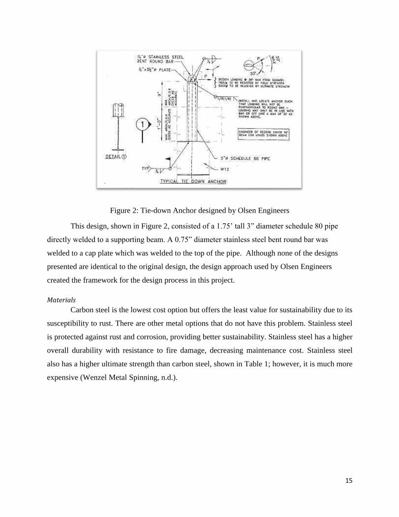
Figure 2: Tie-down Anchor designed by Olsen Engineers
This design, shown in Figure 2, consisted of a 1.75’ tall 3” diameter schedule 80 pipe
directly welded to a supporting beam. A 0.75” diameter stainless steel bent round bar was
welded to a cap plate which was welded to the top of the pipe. Although none of the designs
presented are identical to the original design, the design approach used by Olsen Engineers
created the framework for the design process in this project.
Materials
Carbon steel is the lowest cost option but offers the least value for sustainability due to its
susceptibility to rust. There are other metal options that do not have this problem. Stainless steel
is protected against rust and corrosion, providing better sustainability. Stainless steel has a higher
overall durability with resistance to fire damage, decreasing maintenance cost. Stainless steel
also has a higher ultimate strength than carbon steel, shown in Table 1; however, it is much more
expensive (Wenzel Metal Spinning, n.d.).

16
Table 1: Ultimate and Yield Strength of Carbon vs. Stainless Steel , values based on AISC Table
2-4
Material Yield Strength Ultimate Strength
ASTM A53 Grade B Carbon Steel 35 ksi 60 ksi
ASTM A240: 316 Stainless Steel 30 ksi 75 ksi
Another option is galvanized steel. Hot dipped galvanizing carbon steel has a small
additional cost but gives the steel the protection it needs from corrosion with a layer of zinc
covering all surfaces. However, welding materials that have already been galvanized can create a
poisonous gas due to the reaction between the zinc and the copper (Wenzel Metal Spinning). The
safety concerns to the welders and expense of safety precautions have to been taken into account
when choosing or not choosing a design with galvanized members.
Sustainability
Leadership in Energy & Environmental Design (LEED) provides a framework for creating
and maintaining green building designs through the design, construction and operation processes
(About LEED, 2015). LEED applies to all building types such as residential, educational, retail,
hospitality, healthcare, and existing buildings. Many construction projects strive to become
LEED certified by fulfilling a list of criteria which involve achieving high performance in areas
of human and environmental health.
One of the main goals of LEED is to reduce material waste. The addition of permanent roof
anchors to a building is applying the idea of reusing materials for multiple purposes, versus using
temporary supports each time a lifeline is needed.
Another way to keep material waste low is ordering the pipes and bent bars in readily
available dimensions. The materials should be ordered in dimensions that can be cut down into
the needed size with the least amount of waste.
Geometry
The geometry of the anchor design can greatly affect the strength. For a given applied
load, a reduction in the height of the pipe cause lower moments and therefore stresses on the
pipe. Although the reduction is beneficial, the pipe height has to be tall enough that it extends

17
past roof decking; keeping the attachment point accessible after the roof is complete. This is
recommended to be a minimum of one foot.
A change in diameter or schedule of the pipe causes changes in the moment of inertia and
area of the cross section, therefore also changing the stresses within the pipe. A change in the
radius of the top curved beam affects the bending stresses throughout the curved member. These
changes in the geometry also cause changes in the weight which affect the cost of the anchor.
Bending Stress of Curved Beam
The bending stress of a beam is equal to My/I when the beam is straight. When a member
is curved, the neutral axis no longer passes through the centroid of the member. The figure below
shows the dimensions of the values used in the calculation.
Figure 3: Three radii used in the bending stress calculation of a curved beam
The three radii from the center of curvature, O, are identified as 𝑟, R, and r. The radius 𝑟,
is the distance from the center of curvature to the centroid of the member. R is the distance from
O to the neutral axis of the bent member. Due to bending, different strains are caused at the top
and bottom of the member, shifting the neutral axis from the centroid of the cross section. The

18
neutral axis is the axis in the member where no stress or strain is acting. The third radius, r, is the
distance from the center of curvature to any arbitrary point the stress is being calculated at.
The equation used to calculate the location of the neutral axis is the area of the cross
section over the integral of the area in respect to the radius, 𝑅 =𝐴
(𝑑𝐴
𝑟). (Hibbeler, 2010).The
integral can either be calculated by hand or looked up in a table of various geometries.
Once R has been found, the bending stress is simple to calculate. The equation of the
bending stress in a curved member is 𝜎 =𝑀(𝑅−𝑟)
𝐴𝑟(𝑟−𝑅). The stress should be found at both the inside
and outside of the beam to find which point is critical.
RISA3D
RISA3D is an engineering computer program used to analyze three-dimensional models
and to draw designs (Risa3D, 2015). The program allows the user to design with many materials
such as hot rolled steel, cold rolled steel, masonry, timber, concrete, etc., as well as many shapes
like wide flange beams, hollow structural section columns, pipes, and so many more. Users also
have the option of placing nodes in specific coordinates and creating their members to extend
from one node to another. Figure 4 shows the top bent bar of the roof anchor drawn in RISA3D.
Figure 4: RISA3D drawing of top bent bar
19
Many load types can be applied to designs in the programs. These include nodal, point,
moving, surface and distributed loads. Multiple load cases can be programmed to solve the
design multiple times. The easy-to-use solver gives instant results for reactions, stresses and
deflections, making calculations take significantly less time than calculating by hand, while
providing code checks for the design.
Structural Capacity
While designing the anchor many checks and calculations were made to ensure structural
integrity. The strength of the materials and welds were calculated to ensure they could withhold
the minimum of strength of 5000 pounds, required by OSHA standards.
The two most common design philosophies for structural steel are Load and Resistance
Factor Design (LRFD) and Allowable Stress Design (ASD). Until 1986, when AISC introduced
LRFD specifications in their Steel Construction Manual, steel structures were solely built with
the ASD approach. ASD uses a stress based strategy, keeping force levels below the member’s
yield by dividing the nominal strength by a factor larger than one, omega. The LRFD approach
determines the required strength of members. This was done through the application of a strength
reduction factor, phi. Phi is a factor, always less than one, that reduces the strength of members
to ensure the designs can handle, at minimum, the calculated stresses.
Throughout this project, LRFD approach was used to check the strengths of the members
in the anchor design. The value phi factors applied are found in codes and construction specifics
governed by AISC (American Institution of Steel Construction). These values are also shown in
Table 2.

20
Table 2: Table of Resistance Factors Used in LRFD Calculations
Strength Calculation Resistance, Phi, Factor Per AISC Reference
Axial Tension and Bending,
Yield
Φ = 0.9 AISC Section D2
Axial and Bending, Ultimate Φ = 0.75 AISC Section D2
Shear Φ = 0.9 AISC Section G1
Fillet Welds, across effective
throat
Φ = 0.75 AISC Section J2.4
Bolts Φ = 0.75 AISC Section J3.6
Block Shear Rupture Φ = 0.75 AISC Section J4.3
LRFD also uses load combination equations that assign a specific factor for each load
type that are expressed in the equation. The only load consider in the design of the roof anchors
was the 5000 pound ultimate load. Due to it being an “ultimate” load, it was assumed that the
appropriate load factor is included within the value.

21
Chapter Three: Methodology
This section presents the overall methodology of the project. The project consisted of
four major phases: benchmark calculations, preliminary designs, analysis of designs, and detailed
design. A summary of the work completed for each phase can be found in Table 3; this section
will provide an explanation of each phase.
Table 3: Brief explanation of the four phases of the project
Phase Work Included for this Project
Preparation of Benchmark
Calculation Back calculating a precedent anchor design.
Creation of Design Alternatives Multiple simple design alternatives, based on the needs
of the sponsoring company and OSHA’s regulations.
Analysis of Design Alternatives Analysis of preliminary designs to identify the most
effective.
Development of Detailed Design More in-depth design of the chosen design from the
analysis.
Preparation of Benchmark Calculations
Benchmark calculations of a precedent anchor design were done for the purpose of
ensuring the analytical process and calculations used in this MQP project were performed
properly and complied with current standards. This was completed by hand calculating the
required strengths and dimensions to compare to the end values of the previous design. If the end
values are similar the process is more than likely correct and can be used to investigate slightly
varying designs.
These calculations included determining the internal forces and stresses acting on each of
the design elements due to the yielding and ultimate loads of 1800 pounds and 5000 pounds.
Using the calculated internal forces and stresses, the stainless steel SCH 80 pipe and ¾” bent bar
were checked for minimum strength capacities according to their ASTM standard values.
The bent bar calculations included creating tables to determine the stresses at various
locations around the bend. However, the structure of the bent bar was indeterminate which
caused an approach of using virtual work for the analysis of a symmetric structure with an anti-
symmetric loading.

22
Computer analysis in RISA3D was also used to calculate the stresses in the curved beam.
This was used for comparison to check the hand calculated values to ensure accurate results. The
hand calculated values and the computer analysis should not be expected to have identical
results, because the computer results takes axial and shear deformation into account. The
computer model also was not a perfectly curved shape. An difference of less than 20% between
the two results is an acceptable difference. The shear force at the tip of the curve was found by
the RISA3D program and hand calculations at 15 and 15.8 pounds, respectively, with an
acceptable 5% error.
After the maximum stresses acting on the members were determined and checked against
material limits, the weld lengths and strengths were calculated. The bottom of the pipe will be
welded, using an all-around fillet weld, to a flange beam on the roof, or welded to a baseplate
which can be bolted into a supporting beam. The E70 electrode weld had a minimum fillet of
1/4” due to the thickness of the pipe. However, a ¼” fillet weld was found not to be strong
enough due to the shear stress the weld has to endure. It was determined that a minimum of
7/16” fillet weld would be needed to weld the pipe.
The weld of the bent bar to the sides of the pipe was checked using a fillet weld size of
¼” due to the thickness of the bent bars. The minimum required weld length for strength was
calculated as 0.327” which is less than the minimum of four times the fillet size specified by
AISC Table J2.4. Therefore, the minimum weld length is governed by four times the fillet size,
or 1”.
Creation of Design Alternatives
Creating alternative designs was the next step of the design process. The work done to
complete the benchmark design was used as a template to create four, additional preliminary
alternatives. The four main variations in the designs include adding a cap plate, a base plate,
changing the material of the pipe, and changing the dimensions.
Adding a cap plate to the top of the pipe was one of the alternations in the designs. It
distributes the stress from the bent bar around the entire edge of the pipe instead of in two small
sections, but also causes an additional weld that was not included in the benchmark. The cap
plate changes the weld types of the bent bar to the anchor from one–inch long fillet weld down
23
each side of the pipe to three all around welds. The cap plate also decreases the inside radius of
the bent bar causing a slightly higher stress values on the outer radius of the bend while still
being well under the limits.
The initial design included the base of the pipe welded to a roof. Due to the limitation
that direct welding of the anchor is only possible on some metal roofs, an alternative of welding
the pipe to a base plate and then bolting the plate into the roof was suggested. Designing the base
plate required the calculation of the thickness for bending effects using assumed dimensions of
the base plate. Then using the calculated thickness, the possible effects of prying, tension yield,
tension rupture, and block shear rupture were investigated to determine the governing limit state
for plate thickness.
The material of the pipe was also altered in the design. As mentioned in the background,
different metal materials provide various pros and cons. Stainless steel offers protection against
corrosion but it is more costly than carbon steel. Whereas carbon steel, the most common, lowest
cost and most readily available of the choices, has lower ultimate strength than stainless steel but
a higher yielding strength.
The dimensions of the anchor were altered by shortening the height of the pipe, changing
the thickness of the pipe wall, or widening the radius. Widening the radius and thickening the
wall gives the pipe a larger cross sectional area, strengthening the pipe against axial and bending
stress failures. However it also gives the pipe a larger slenderness factor and weakens the pipe
against failure due to buckling. Shortening the height on the other hand can decrease the
maximum moment, therefore decreasing the bending stress in the pipe. These dimensions were
changed relatively to the previously produced design, causing improvement without decreasing
the constructability of the design.
The five designs, including the benchmark were created. Below is a table showing a brief
explanation of the five designs.

24
Table 4: Brief design summary of alternatives
Design Number Design Highlights
1 (Benchmark) 3" Diameter ASTM A316 Sch 80 Pipe, 1.75' 0.75" Diameter ASTM A316 Bent Bar
Field Weld to Roof
2 3" Diameter ASTM A316 Sch 80 Pipe, 1.5' ASTM A316 Round PL 3.5" x 3/8"
0.75" Diameter ASTM A316 Bent Bar Field Weld to Roof
3 ASTM A53 Grade B 3" Diameter Sch 80 Pipe, 1.75' 0.75" Diameter ASTM A316 Bent Bar
ASTM A316 Round PL 3.5" x 3/8" ASTM A316 Base PL 12" x 12" x 7/16"; Bolted to
Roof
4
4" Diameter ASTM A316 Sch 80 Pipe, 1.5' 0.75" Diameter ASTM A316 Bent Bar
Field Weld to Roof
5
3" Diameter ASTM A316 Sch 80 Pipe, 1.75' 0.75" Diameter ASTM A316 Bent Bar
ASTM A316 Base PL 12" x 12" x 7/16"; Bolted to Roof
Analysis of Design Alternatives
Each of the alternative designs was analyzed to select the most efficient option
considering the perspectives of sustainability, constructability, use flexibility, and cost. Each
alternative was rated for its sustainability, constructability, and use flexibility with a score
between one and four.
The sustainability of each design was assessed including protection against corrosion and
overall durability. The leading differing factor in the five designs was the pipe material using
both A316 stainless steel and ASTM A53 Grade B carbon steel. Stainless steel is protected
against rust and corrosion, providing better sustainability as well as overall better durability with
resistance to fire damage. ASTM A53 Grade B carbon steel is the lowest cost option but offers a
smaller value of sustainability due to its susceptibility to rust.
The constructability of the design considered ease of fabrication for MIW Corporation.
The three sub-factors of constructability factors included component fabrication, assembly and
field installation. Component fabrication includes the shop’s limitations in bending the top bar of
the anchor. Assembly factors were discussed with MIW’s shop manager to compare the
difficultly of the different welds. Some of the topics discussed included weld types or the

25
difficultly welding carbon and stainless steel together. The last constructability factor analyzed
was the field installation process for the anchor. Bolting a baseplate to a roof is an easier process
than field welding the anchor onto a high roof. The average of the three constructability subarea
scores was the final constructability score.
The use flexibility of the design took into account the ability to use the anchor designs in
various locations. For example, direct welding the anchor is only possible with some metal roofs.
If the roof is constructed with concrete, the pipe cannot be welded directly to the roof. Bolting
the anchors that were welded to base plates creates a more versatile alternative.
To balance the scoring values of the three attributes, a weighted scoring equation was
used. To create proper weights for each of the three attributes, the attributes were all compared
two at a time. It was found that sustainability was the most important of three, and
constructability was more important than the use flexibility. In order to avoid disregarding use
flexibility due to its score of zero, a nominal score of one was used, increasing each of the scores
by one. The weight factors were used to create the final scoring equation of:
Design Score =∑ (
36
∗ 𝑆𝑢𝑠𝑡𝑎𝑖𝑛𝑎𝑏𝑖𝑙𝑖𝑡𝑦 +26
∗ 𝐶𝑜𝑛𝑠𝑡𝑟𝑢𝑐𝑡𝑎𝑏𝑖𝑙𝑖𝑡𝑦 +16
∗ 𝑈𝑠𝑒 𝐹𝑙𝑒𝑥𝑖𝑏𝑖𝑙𝑖𝑡𝑦)
𝐶𝑜𝑠𝑡∗ 100
A cost analysis was completed for each design using take-offs. Cost estimates with the
company’s metal supplier were made to create the most accurate estimates available. A balance
between use flexibility, sustainability, constructability and cost was desired. The cost
comparisons of the different materials and dimensions of materials helped give a value for the
different scores presented by the other three main attributes. The design decision balanced
between all of the factors in the table. An equation dividing the attributes of the design by the
cost was created to identify the best value solution.
Development of Detailed Design
In the results of the analysis, the best value solution was Design #3. However, the fifth
design was a close second. Although Design #3 was chosen by the scoring, MIW Corporation
expressed reservations about the welding the stainless steel and carbon steel together. It was
expressed that stainless steel was the preferred material for all of the elements.
26
The final, recommended design is a variation of Design #5 by shortening the A316
stainless steel pipe to 1.5 feet, thereby reducing the maximum moment on the bottom on the pipe
and lessening the fillet weld. The values of the stresses in the design were all recalculated and
checked for proper strengths and specifications.
Shortening the height, while still keeping in mind minimum heights for the attachment to
remain above the decking, also lessened the cost of the pipe, which is the most expensive
member of the design. The efficiency of the design was rescored, and was calculated at higher
than previous highest scorer.
Final AutoCAD drawings were created for the recommended design which can be viewed
in Appendix S.
27
Chapter Four: Preparation of Benchmark Calculations
The first step in the design process was creating a benchmark design. Benchmarking is a
process used to compare and base one’s own designs and processes to industry’s best practices.
The purpose of making benchmark calculations was to ensure the analytical process and
calculations used in this MQP project were performed properly and complied with current
standards. If the required strengths and dimensions can be calculated with similar end values as
the previous designs, the process is more than likely correct and can be used to investigate
slightly varying designs.
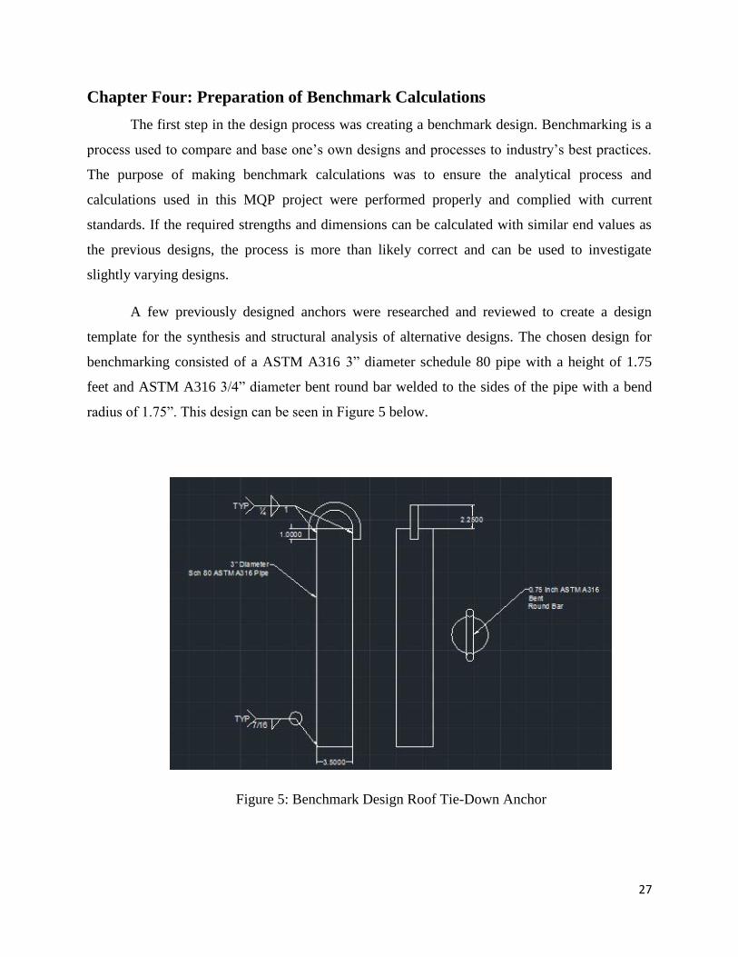
A few previously designed anchors were researched and reviewed to create a design
template for the synthesis and structural analysis of alternative designs. The chosen design for
benchmarking consisted of a ASTM A316 3” diameter schedule 80 pipe with a height of 1.75
feet and ASTM A316 3/4” diameter bent round bar welded to the sides of the pipe with a bend
radius of 1.75”. This design can be seen in Figure 5 below.
Figure 5: Benchmark Design Roof Tie-Down Anchor

28
The analytical calculations for this design can also be seen in Appendix C. These
calculations included determining the internal forces and stresses acting on each of the design
elements due to the yielding and ultimate loads. The ultimate load of 5000 pounds is governed
by OSHA. Using these internal forces and stresses, the stainless steel SCH 80 pipe and ¾” bent
bar were checked for minimum yielding and ultimate strength capacities according to their
ASTM (American Society for Testing and Materials) standard values.
LRFD philosophy was used through the application of a strength reduction factor, phi, to
ensure the designs can handle, at minimum, the calculated stresses. The value phi factors applied
were found in codes and construction specifics governed by AISC.
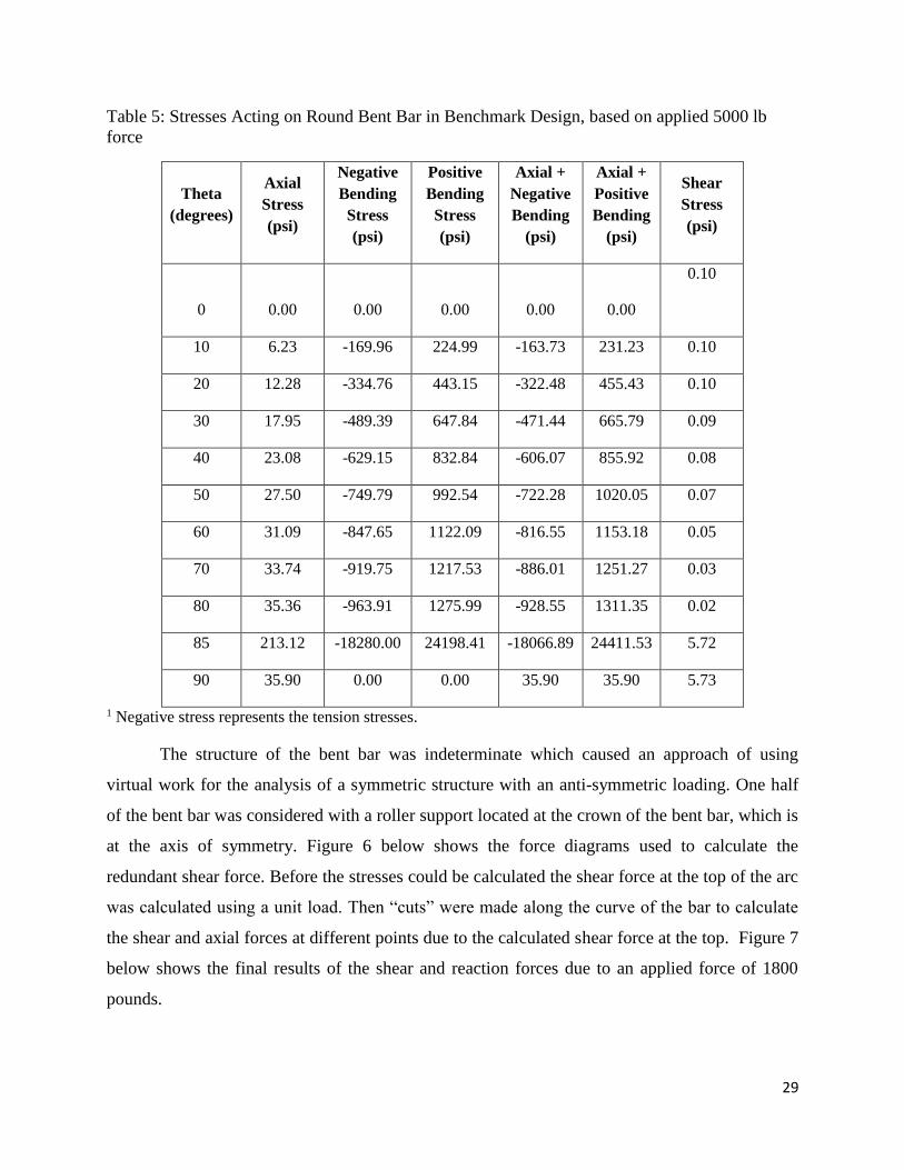
The bent bar calculations included creating tables to determine the axial, bending and
shear stresses at various locations around the bend. Stresses due to the 5000 pound ultimate load
can be found in Table 5. Negative stress values represent the member being in tension.
29
Table 5: Stresses Acting on Round Bent Bar in Benchmark Design, based on applied 5000 lb
force
Theta
(degrees)
Axial
Stress
(psi)
Negative
Bending
Stress
(psi)
Positive
Bending
Stress
(psi)
Axial +
Negative
Bending
(psi)
Axial +
Positive
Bending
(psi)
Shear
Stress
(psi)
0 0.00 0.00 0.00 0.00 0.00
0.10
10 6.23 -169.96 224.99 -163.73 231.23 0.10
20 12.28 -334.76 443.15 -322.48 455.43 0.10
30 17.95 -489.39 647.84 -471.44 665.79 0.09
40 23.08 -629.15 832.84 -606.07 855.92 0.08
50 27.50 -749.79 992.54 -722.28 1020.05 0.07
60 31.09 -847.65 1122.09 -816.55 1153.18 0.05
70 33.74 -919.75 1217.53 -886.01 1251.27 0.03
80 35.36 -963.91 1275.99 -928.55 1311.35 0.02
85 213.12 -18280.00 24198.41 -18066.89 24411.53 5.72
90 35.90 0.00 0.00 35.90 35.90 5.73
1 Negative stress represents the tension stresses.
The structure of the bent bar was indeterminate which caused an approach of using
virtual work for the analysis of a symmetric structure with an anti-symmetric loading. One half
of the bent bar was considered with a roller support located at the crown of the bent bar, which is
at the axis of symmetry. Figure 6 below shows the force diagrams used to calculate the
redundant shear force. Before the stresses could be calculated the shear force at the top of the arc
was calculated using a unit load. Then “cuts” were made along the curve of the bar to calculate
the shear and axial forces at different points due to the calculated shear force at the top. Figure 7
below shows the final results of the shear and reaction forces due to an applied force of 1800
pounds.

30
Figure 6: Force Diagrams of Virtual Work of a Half structure with Anti-Symmetric Boundary
Condition
Figure 7: Final Results of Shear and Reaction Forces

31
From these found forces, the stresses in each element were calculated. The bending stress
had to be calculated for a curved beam versus a typical straight beam in the bent bar. Refer to
“Bending Stress of a Curved Beam” in the background for more information about bending
stress in the curved members.
Figure 8: Joint reaction results from computer analysis
Computer analysis in RISA3D was also used to calculate the stresses in the curved beam.
This was used for comparison to check the hand calculated values to ensure accurate results. The
computer results takes more shear deformation into account which causes slightly different
results. The computer model also was not a perfectly curved shape. The model was digitized by
21 nodes about 10 degrees apart, which were all connected by individual members. The hand
calculated values and the computer analysis should not be expected to have identical results. The
shear force at the tip of the curve was found by the RISA3D program and hand calculations at 15
and 15.8 pounds, respectively, with an acceptable 5% error.
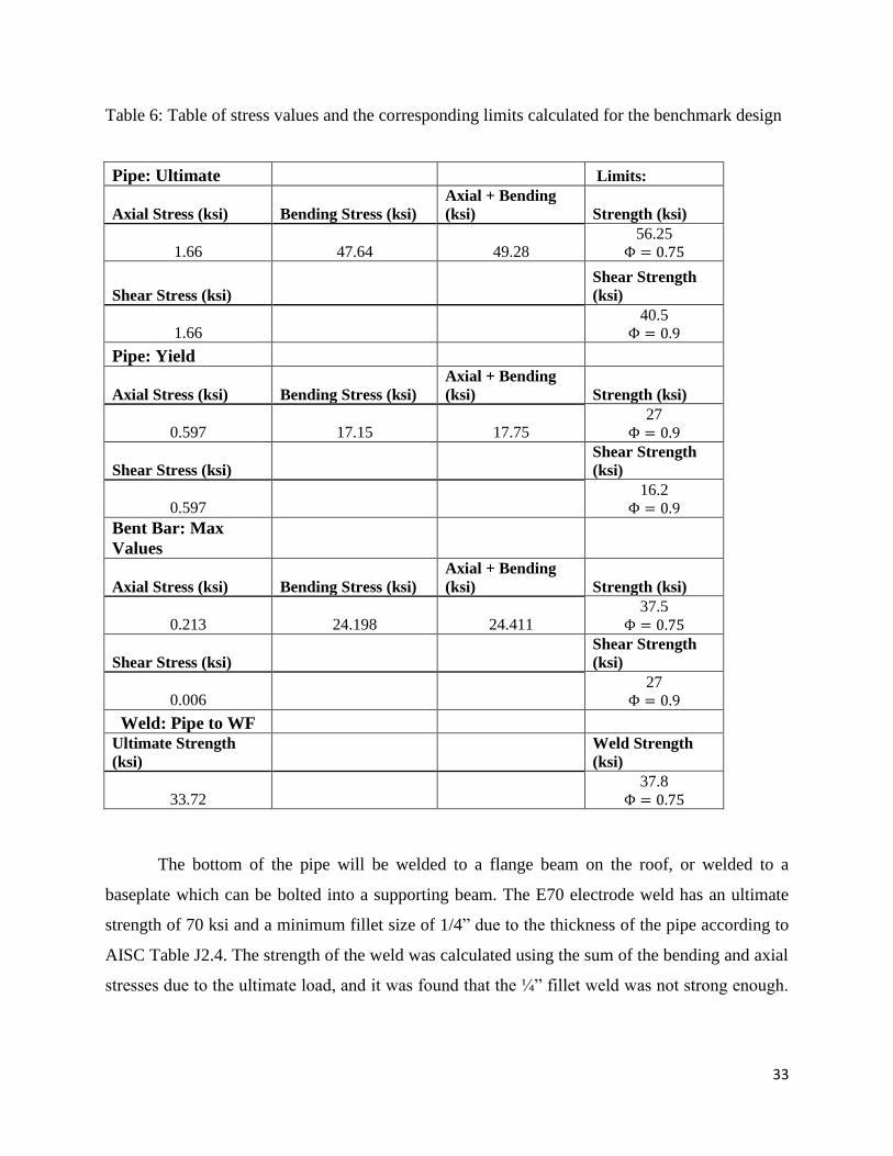
After the maximum stresses acting on the members were determined and checked against
material limits, the weld lengths and strengths were calculated. These limiting equations and
calculated values can be seen in Table 6 below. Throughout the calculations of the stresses the
Load and Resistance Factor Design (LRFD) approach was used which determines the required
strength of members. This was done through the application of a strength reduction factor, phi.
Phi is a factor, always less than one, which reduces the strength of members to ensure the
designs can handle, at minimum, the calculated stresses. The value phi factors applied were
found in codes and construction specifics governed by AISC (American Institution of Steel
Construction).

32
33
Table 6: Table of stress values and the corresponding limits calculated for the benchmark design
Pipe: Ultimate Limits:
Axial Stress (ksi) Bending Stress (ksi)
Axial + Bending
(ksi) Strength (ksi)
1.66 47.64 49.28 56.25
Φ = 0.75
Shear Stress (ksi) Shear Strength
(ksi)
1.66 40.5
Φ = 0.9
Pipe: Yield
Axial Stress (ksi) Bending Stress (ksi)
Axial + Bending
(ksi) Strength (ksi)
0.597 17.15 17.75 27
Φ = 0.9
Shear Stress (ksi)
Shear Strength
(ksi)
0.597 16.2
Φ = 0.9
Bent Bar: Max
Values
Axial Stress (ksi) Bending Stress (ksi)
Axial + Bending
(ksi) Strength (ksi)
0.213 24.198 24.411 37.5
Φ = 0.75
Shear Stress (ksi) Shear Strength
(ksi)
0.006 27
Φ = 0.9
Weld: Pipe to WF
Ultimate Strength
(ksi)
Weld Strength
(ksi)
33.72 37.8
Φ = 0.75
The bottom of the pipe will be welded to a flange beam on the roof, or welded to a
baseplate which can be bolted into a supporting beam. The E70 electrode weld has an ultimate
strength of 70 ksi and a minimum fillet size of 1/4” due to the thickness of the pipe according to
AISC Table J2.4. The strength of the weld was calculated using the sum of the bending and axial
stresses due to the ultimate load, and it was found that the ¼” fillet weld was not strong enough.
34
After multiple trail-and-error calculations, it was determined that a minimum of 7/16” fillet weld
would be needed to weld the pipe to the supporting beam flange or baseplate.
Next the weld of the bent bar to the sides of the pipe was investigated. The minimum
fillet weld size is ¼” due to the thickness of the bent bars, according to AISC Table J2.4. The
minimum weld length was calculated using the strength per inch of weld. The minimum length
was found to be 0.327” which is less than the minimum of four times the fillet size per AISC
Specification section J2.2b. Therefore, the minimum weld length is governed by four times the
fillet size, or 1”.
Taking the time to understand a benchmark design assisted in the understanding of
creating the alternative designs. It also helped to brainstorm the different concepts and criteria to
consider while designing and then analyzing the alternative designs.

35
Chapter Five: Creation of Alternative Designs
Creating multiple preliminary designs was the next phase of the design process. Each
design satisfies the constraints imposed by the needs of the sponsoring company, and they also
follow the specifications for tieback anchors defined by the Occupational Safety and Health
Administration (OSHA). In order to obtain the proper information about the specifications,
background research was completed through OSHA, ANSI, and AISC (American Institute of
Steel Construction).
The work done to complete the benchmark design was used as a template for the design
and structural analysis of four other alternatives. Some of the variations in the designs include
adding a cap plate, a base plate, changing the dimensions, and changing the material of the pipe.
As mentioned above, the work done on the benchmark design simplified the design
process for the four other alternatives.
Cap Plate
One of the changes included adding a cap plate to the top of the pipe. It distributes the
stress from the bent bar around the entire edge of the pipe instead of in two small sections. This
causes an addition of a weld that was not included in the benchmark which also adds cost for the
weld itself and the cap plate. The weld changes can be seen in the two figures below.
Figure 9: Bent Bar Connection with a Cap
Plate
Figure 10: Bent Bar Connection without a Cap
Plate
As shown in the two figures above, the cap plate changes the weld types of the bent bar
to the anchor. Without the cap plate the bent bar is connected by a one -inch long fillet weld
down each side of the pipe. With the cap plate, there are three all around welds. One to connect
the cap plate to the pipe, and a second to connect the two ends of the bent bar to the cap plate.

36
Initially the inside radius of the bent bar was welded to the outside of the pipe. When
welded to the cap plate, the outside radius of the bent bar is at the end of the pipe, shortening the
radius. This causes a slightly higher stress values at the outer radius while still being well under
the limits.
Base Plate
The initial design considered the base of the pipe directly welded to a roof. Depending on
the structure of the roof, this can be a strong and simple permanent solution. However this is
only possible on some metal roofs. If the roof is constructed with concrete, the pipe cannot be
welded directly to the roof. Alternatives include welding the pipe to a base plate, and then
bolting the plate into the roof with anchor bolts.
Designing the base plate required the calculation of the thickness for bending using
assumed dimensions of the base plate. The base plates of the anchor designs were also checked
for the possibility of prying action (AISC 9-10). The effect of prying action happens only in
bolted connection when a tensile force acts on a bolt (McCormac, 2011). The bolt’s tension force
is affected by the deformation of the thin plate being bolted down. When checking the minimum
thickness of the plate to check its strength against prying action, a plate thickness was chosen so
prying action did not have to be considered.
Then, using the calculated thickness, the in-plane effects of tension yield, tension rupture,
and block shear rupture were investigated to determine the governing value of the three
calculations.

37
Figure 11: Drawing of the typical baseplate design and bolt placement
Next, the total permissible capacity of the base plate was found as the limit of the
governing value between the tension yield, tension rupture, and block shear rupture to ensure
baseplate is strong enough against the three common failure methods.
A-325N, the one of the most commonly used structural bolts, was chosen for the design.
For this application, the bolt strength is governed by combined shear and tension (AISC J3.7).
AISC equations J3-2 and J3-3b were used to calculate the available tensile strength subjected to
combined tensile and shear of the bolts at 39.6 kips per bolt if four bolts are used. The required
capacity was also checked to ensure it is less than the available capacity. Consideration has to be
taken in deciding between constructability of field welding and bolting through a roof.
Pipe Material
Another alternative to the design was modifying the material of the pipe. As mentioned in
the background, different metal materials provide various pros and cons. Stainless steel offers
protection against corrosion but it is more costly than carbon steel.
Galvanizing is an alternative for corrosion protection with less added cost than stainless
steel. However, the health concern with welding galvanized metal is not worth the corrosion
protection unless the proper equipment is readily available to protect the welder from these
dangers.
38
Carbon steel, the most common and most readily available of the choices, has lower
ultimate strength than stainless steel but a higher yielding strength. Carbon steel is also the least
cost option for the initial cost, while also the least sustainable.
Dimensions of the Pipe
The dimensions of the anchor can be altered by shortening the height of the pipe,
changing the thickness of the pipe or widening the radius. Widening the radius and thickening
the wall can give the pipe a higher slenderness factor which may make the pipe more susceptible
to buckling while the greater cross-sectional area strengthens the pipe against axial stresses. This
also increases the weight per foot of the pipe and therefore the cost.
Shortening the height on the other hand can decrease the maximum moment, therefore
decreasing the bending stress in the pipe. This also decreases the cost of the pipe, making the
design more cost effective if the design can still handle all the stresses.
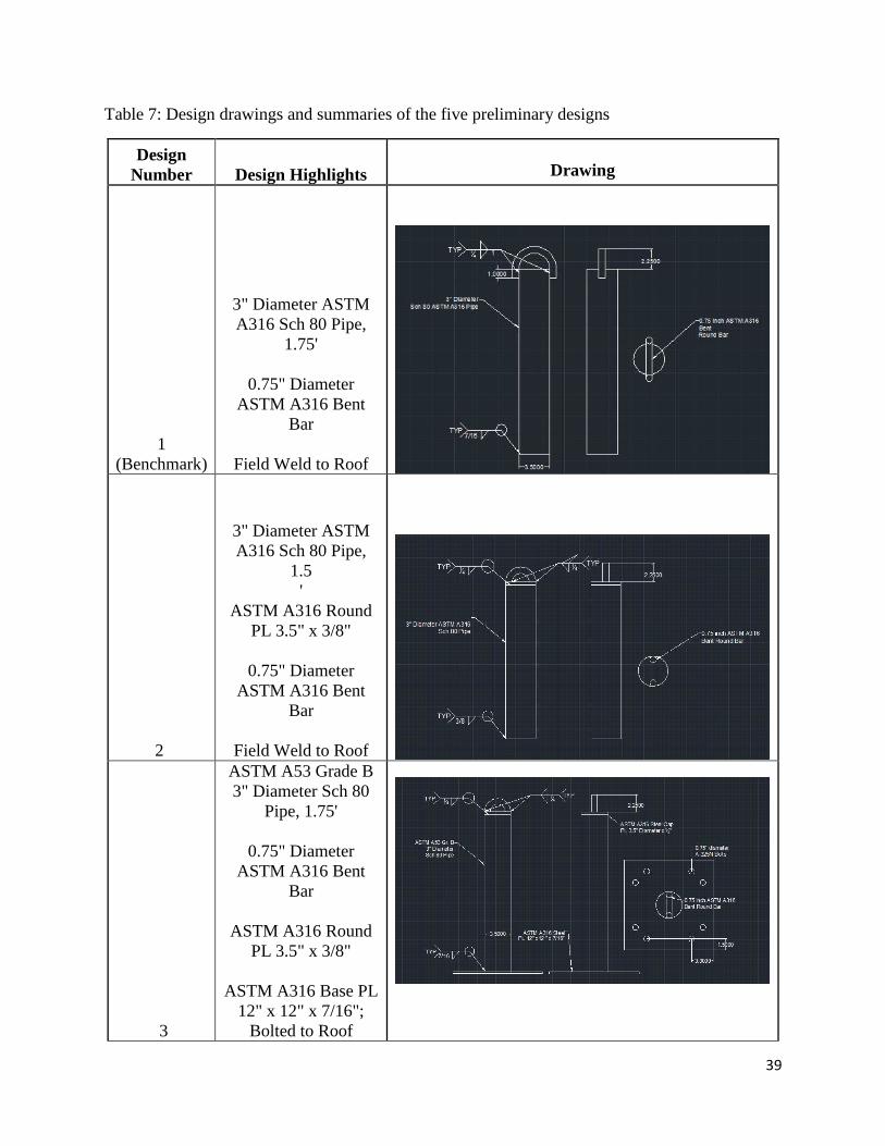
The five designs, including the benchmark were created. In Table 7 are drawings of each
of the designs and design summaries.
39
Table 7: Design drawings and summaries of the five preliminary designs
Design
Number Design Highlights
Drawing
1
(Benchmark)
3" Diameter ASTM
A316 Sch 80 Pipe,
1.75'
0.75" Diameter
ASTM A316 Bent
Bar
Field Weld to Roof
2
3" Diameter ASTM
A316 Sch 80 Pipe,
1.5
'
ASTM A316 Round
PL 3.5" x 3/8"
0.75" Diameter
ASTM A316 Bent
Bar
Field Weld to Roof
3
ASTM A53 Grade B
3" Diameter Sch 80
Pipe, 1.75'
0.75" Diameter
ASTM A316 Bent
Bar
ASTM A316 Round
PL 3.5" x 3/8"
ASTM A316 Base PL
12" x 12" x 7/16";
Bolted to Roof

40
4
4" Diameter ASTM
A316 Sch 80 Pipe, 1.5'
0.75" Diameter ASTM
A316 Bent Bar
Field Weld to Roof
5
3" Diameter ASTM
A316 Sch 80 Pipe,
1.75'
0.75" Diameter ASTM
A316 Bent Bar
ASTM A316 Base PL
12" x 12" x 7/16
"; Bolted to Roof
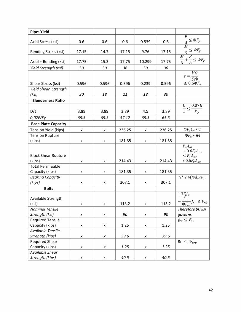
Below in Table 8, the summary of stresses and limiting strength values can be seen and
compared. As shown in the table, most of the members and connections are overdesigned. The
overdesign was a result of considering the constructability of the design immediately in the
design process. The base design was Olsen Engineer’s roof anchor which consisted of a 0.75”
round bar and 3” diameter Sch 80 pipe with a height of 1.75 feet. Although the diameter of the
pipe could have been reduced slightly, the bend radius would also decrease, therefore making the
fabrication of the top, round bar more difficult.

41
Table 8: The design summary and stress values of the five preliminary designs
Design #1 Benchmark
Design #2
Design #3
Design #4
Design #5
Limiting Equations
Bent Bar: Max Values
Axial Stress (ksi) 0.213 0.467 0.467 0.403 0.213 𝑃
𝐴≤ Φ𝐹𝑢
Bending Stress (ksi) 24.198 26.911 26.911 27.189 24.198
[𝑀(𝑅 − 𝑟)]
[𝐴𝑟(𝑟 − 𝑅)]
≤ Φ𝐹𝑢
Axial + Bending (ksi) 24.578 27.379 27.379 27.592 24.578
[𝑀(𝑅 − 𝑟)]
[𝐴𝑟(𝑟 − 𝑅)]
+𝑃
𝐴≤ Φ𝐹𝑢
Strength (ksi) 50 50 50 50 50
Shear Stress (ksi) 0.006 0.006 0.002 0.36 0.36
𝜏 =𝑉𝑄
𝑆𝑐𝑏≤ 0.6Φ𝐹𝑢
Shear Strength (ksi) 30 30 30 30 30
Cap Plate: Ultimate
Axial Stress (ksi) x 0.744 0.744 x X 𝑃
𝐴≤ Φ𝐹𝑢
Bending Stress (ksi) x 0.52 0.52 x X 𝑀
𝑆≤ Φ𝐹𝑢
Axial + Bending (ksi) x 1.264 1.264 x X 𝑀
𝑆+
𝑃
𝐴≤ Φ𝐹𝑢
Strength (ksi) x 65 65 x X
Shear Stress (ksi) x 2.023 2.023 x X
𝜏 =𝑉𝑄
𝑆𝑐𝑏≤ 0.6Φ𝐹𝑢
Shear Strength (ksi) x 39 39 x X
Pipe: Ultimate
Axial Stress (ksi) 1.64 1.651 1.64 1.5 1.64 𝑃
𝐴≤ Φ𝐹𝑢
Bending Stress (ksi) 47.64 40.9 47.64 27.14 47.64 𝑀
𝑆≤ Φ𝐹𝑢
Axial + Bending (ksi) 49.28 42.551 49.28 28.64 49.28 𝑀
𝑆+
𝑃
𝐴≤ Φ𝐹𝑢
Ultimate Strength (ksi) 75 75 60 75 75
Shear Stress (ksi) 1.66 1.65 1.66 0.66 1.65
𝜏 =𝑉𝑄
𝑆𝑐𝑏≤ 0.6Φ𝐹𝑢
Ultimate Shear Strength (ksi) 45 45 35 45 45
42
Pipe: Yield
Axial Stress (ksi) 0.6 0.6 0.6 0.539 0.6 𝑃
𝐴≤ Φ𝐹𝑦
Bending Stress (ksi) 17.15 14.7 17.15 9.76 17.15 𝑀
𝑆≤ Φ𝐹𝑦
Axial + Bending (ksi) 17.75 15.3 17.75 10.299 17.75 𝑀
𝑆+
𝑃
𝐴≤ Φ𝐹𝑦
Yield Strength (ksi) 30 30 36 30 30
Shear Stress (ksi) 0.596 0.596 0.596 0.239 0.596
𝜏 =𝑉𝑄
𝑆𝑐𝑏≤ 0.6Φ𝐹𝑦
Yield Shear Strength (ksi) 30 18 21 18 30
Slenderness Ratio
D/t 3.89 3.89 3.89 4.5 3.89
𝐷
𝑡≤
0.07𝐸
𝐹𝑦
0.07E/Fy 65.3 65.3 57.17 65.3 65.3
Base Plate Capacity
Tension Yield (kips) x x 236.25 x 236.25 Φ𝐹𝑦(L ∗ t)
Tension Rupture (kips) x x 181.35 x 181.35
Φ𝐹𝑢 ∗ Ae
Block Shear Rupture (kips) x x 214.43 x 214.43
𝐹𝑢𝐴𝑛𝑡
+ 0.6𝐹𝑢𝐴𝑛𝑣
≤ 𝐹𝑢𝐴𝑛𝑡
∗ 0.6𝐹𝑦𝐴𝑔𝑣
Total Permissible Capacity (kips) x x 181.35 x 181.35
Bearing Capacity (kips) x x 307.1 x 307.1
N* 2.4(Φ𝑑𝑏𝑡𝐹𝑢)
Bolts
Available Strength (ksi) x x 113.2 x 113.2
1.3𝐹𝑛′𝑡
−𝐹𝑛𝑡
Φ𝐹𝑛𝑣𝑓𝑟𝑣 ≤ 𝐹𝑛𝑡
Nominal Tensile Strength (ksi) x x 90 x 90
Therefore 90 ksi governs
Required Tensile Capacity (kips) x x 1.25 x 1.25
𝑓𝑟𝑣 ≤ 𝐹𝑛𝑣
Available Tensile Strength (kips) x x 39.6 x 39.6
Required Shear Capacity (kips) x x 1.25 x 1.25
Rn ≤ Φ𝑓𝑟𝑣
Available Shear Strength (kips) x x 40.5 x 40.5
43
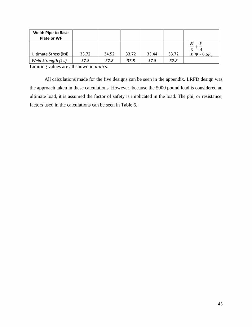
Weld: Pipe to Base Plate or WF
Ultimate Stress (ksi) 33.72 34.52 33.72 33.44 33.72
𝑀
𝑆+
𝑃
𝐴≤ Φ ∗ 0.6𝐹𝑢
Weld Strength (ksi) 37.8 37.8 37.8 37.8 37.8
Limiting values are all shown in italics.
All calculations made for the five designs can be seen in the appendix. LRFD design was
the approach taken in these calculations. However, because the 5000 pound load is considered an
ultimate load, it is assumed the factor of safety is implicated in the load. The phi, or resistance,
factors used in the calculations can be seen in Table 6.
44
Chapter Six: Analysis of Alternatives
Each alternative was analyzed to select the most efficient design. The perspectives of
sustainability, constructability, use flexibility, and cost were all considered.
Evaluation Criteria
Sustainability in construction is growing in importance. Due to this, the sustainability of
each design was rated. Sustainability factors considered included protection against corrosion
and overall durability. The leading differing factor in the five designs was the pipe material. Four
of the designs used stainless steel to protect was against rust and corrosion, providing better
sustainability. It also has an overall better durability with resistance to fire damage than carbon
steel, decreasing maintenance cost. ASTM A53 Grade B carbon steel was used in one of the
alternative designs. It is the lowest cost option but offers the lesser value for sustainability due to
its susceptibility to rust.
The constructability of the design included the capabilities of MIW’s shop to fabricate
the design, as well as the ease of construction in the field. The constructability of the design was
considered throughout the design of the anchor, taking into account the previously produced
design. The three sub-factors of constructability included component fabrication, assembly and
installation. In component fabrication, for example, the shop is limited to minimum radius the
top bent bar can have. An example of an assembly difference is the type of weld used to attach
the top bent bar to the anchor. Three of the designs use a 1” weld length down the side of the
pipe, while the other two weld the ends of the pipe to a cap plate. According to the shop manager
of MIW, Michael Walker, the weld to the side of the pipe is much easier for the shop; greater
strength is also given by the larger weld area. Another assembly concern was welding carbon
steel to stainless steel plates which requires a longer, more difficult welding process. The last
constructability factor analyzed was the field installation process for of the anchor. Bolting a
baseplate to a roof is an easier process for the field workers than bringing welding equipment up
to the top of a building. The average of the three constructability subarea scores determined the
final constructability score.
The use flexibility of each design was also considered during the analysis. Depending on
the structure of the roof, the type of installation of the anchor may be limited. For example,
directly welding the anchor is only possible with some metal roofs. If the roof is constructed with
45
concrete, the pipe cannot be welded directly to the roof. Bolting the anchors that were welded to
base plates created an alternative that can be more versatile.
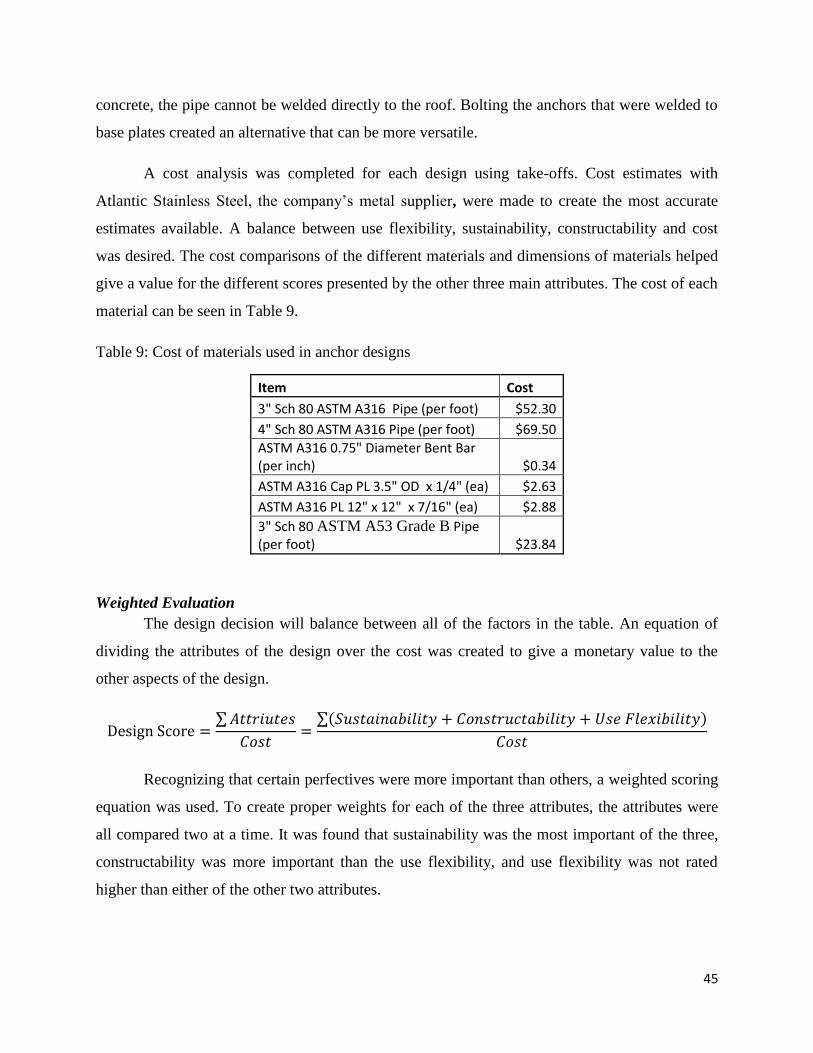
A cost analysis was completed for each design using take-offs. Cost estimates with
Atlantic Stainless Steel, the company’s metal supplier, were made to create the most accurate
estimates available. A balance between use flexibility, sustainability, constructability and cost
was desired. The cost comparisons of the different materials and dimensions of materials helped
give a value for the different scores presented by the other three main attributes. The cost of each
material can be seen in Table 9.
Table 9: Cost of materials used in anchor designs
Item Cost
3" Sch 80 ASTM A316 Pipe (per foot) $52.30
4" Sch 80 ASTM A316 Pipe (per foot) $69.50
ASTM A316 0.75" Diameter Bent Bar (per inch) $0.34
ASTM A316 Cap PL 3.5" OD x 1/4" (ea) $2.63
ASTM A316 PL 12" x 12" x 7/16" (ea) $2.88
3" Sch 80 ASTM A53 Grade B Pipe (per foot) $23.84
Weighted Evaluation
The design decision will balance between all of the factors in the table. An equation of
dividing the attributes of the design over the cost was created to give a monetary value to the
other aspects of the design.
Design Score =∑ 𝐴𝑡𝑡𝑟𝑖𝑢𝑡𝑒𝑠
𝐶𝑜𝑠𝑡=
∑(𝑆𝑢𝑠𝑡𝑎𝑖𝑛𝑎𝑏𝑖𝑙𝑖𝑡𝑦 + 𝐶𝑜𝑛𝑠𝑡𝑟𝑢𝑐𝑡𝑎𝑏𝑖𝑙𝑖𝑡𝑦 + 𝑈𝑠𝑒 𝐹𝑙𝑒𝑥𝑖𝑏𝑖𝑙𝑖𝑡𝑦)
𝐶𝑜𝑠𝑡
Recognizing that certain perfectives were more important than others, a weighted scoring
equation was used. To create proper weights for each of the three attributes, the attributes were
all compared two at a time. It was found that sustainability was the most important of the three,
constructability was more important than the use flexibility, and use flexibility was not rated
higher than either of the other two attributes.
46
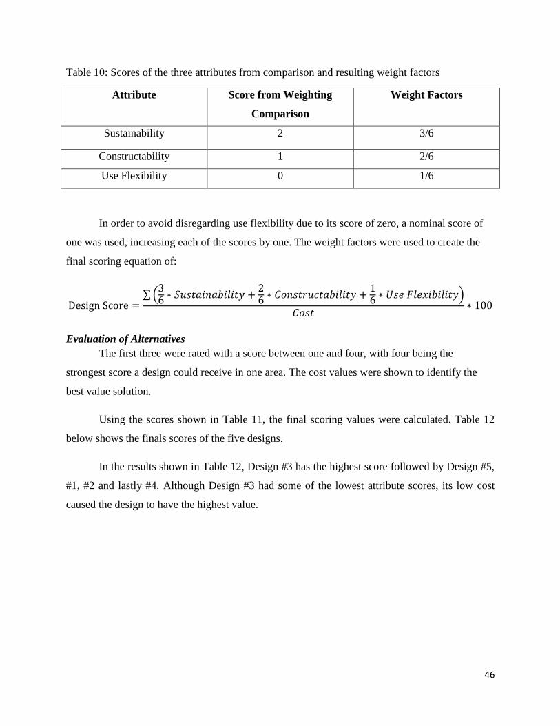
Table 10: Scores of the three attributes from comparison and resulting weight factors
Attribute Score from Weighting
Comparison
Weight Factors
Sustainability 2 3/6
Constructability 1 2/6
Use Flexibility 0 1/6
In order to avoid disregarding use flexibility due to its score of zero, a nominal score of
one was used, increasing each of the scores by one. The weight factors were used to create the
final scoring equation of:
Design Score =∑ (
36 ∗ 𝑆𝑢𝑠𝑡𝑎𝑖𝑛𝑎𝑏𝑖𝑙𝑖𝑡𝑦 +
26 ∗ 𝐶𝑜𝑛𝑠𝑡𝑟𝑢𝑐𝑡𝑎𝑏𝑖𝑙𝑖𝑡𝑦 +
16 ∗ 𝑈𝑠𝑒 𝐹𝑙𝑒𝑥𝑖𝑏𝑖𝑙𝑖𝑡𝑦)
𝐶𝑜𝑠𝑡∗ 100
Evaluation of Alternatives
The first three were rated with a score between one and four, with four being the
strongest score a design could receive in one area. The cost values were shown to identify the
best value solution.
Using the scores shown in Table 11, the final scoring values were calculated. Table 12
below shows the finals scores of the five designs.
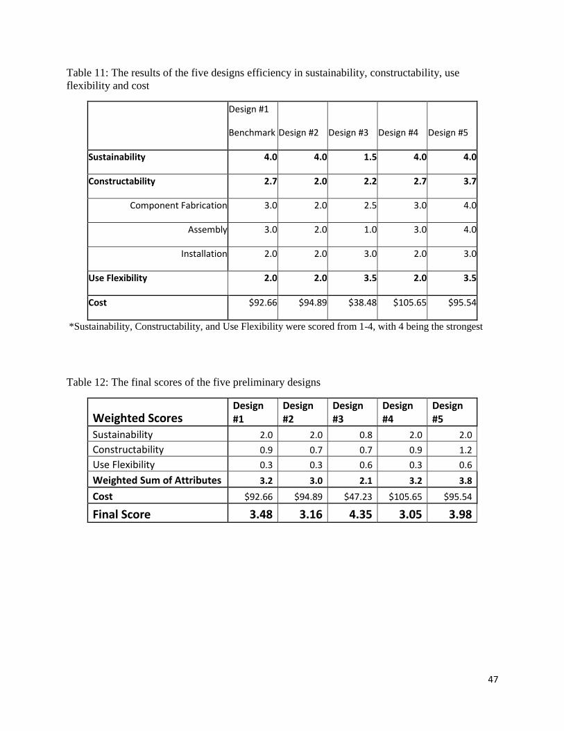
In the results shown in Table 12, Design #3 has the highest score followed by Design #5,
#1, #2 and lastly #4. Although Design #3 had some of the lowest attribute scores, its low cost
caused the design to have the highest value.
47
Table 11: The results of the five designs efficiency in sustainability, constructability, use
flexibility and cost
Design #1
Benchmark Design #2 Design #3 Design #4 Design #5
Sustainability 4.0 4.0 1.5 4.0 4.0
Constructability 2.7 2.0 2.2 2.7 3.7
Component Fabrication 3.0 2.0 2.5 3.0 4.0
Assembly 3.0 2.0 1.0 3.0 4.0
Installation 2.0 2.0 3.0 2.0 3.0
Use Flexibility 2.0 2.0 3.5 2.0 3.5
Cost $92.66 $94.89 $38.48 $105.65 $95.54
*Sustainability, Constructability, and Use Flexibility were scored from 1-4, with 4 being the strongest
Table 12: The final scores of the five preliminary designs
Weighted Scores Design #1
Design #2
Design #3
Design #4
Design #5
Sustainability 2.0 2.0 0.8 2.0 2.0
Constructability 0.9 0.7 0.7 0.9 1.2
Use Flexibility 0.3 0.3 0.6 0.3 0.6
Weighted Sum of Attributes 3.2 3.0 2.1 3.2 3.8
Cost $92.66 $94.89 $47.23 $105.65 $95.54
Final Score 3.48 3.16 4.35 3.05 3.98

48
Chapter Seven: Conclusions and Recommendations
Summary
This project focused on creating an efficient design of a roof tie-down anchor for the use
of a lifeline system. The sponsoring company of this project has produced roof anchors in the
past, but was recently in search of a more efficient design to eventually patent and produce in
bulk.
The process to design an overall efficient design consisted of four phases: evaluation of a
benchmark design, creation of alternatives, analysis of alternatives, and development of a final
design. The overall goal of each of these phases was to design and select a sustainable, easily
constructible, cost effective design that had use flexibility. Throughout all the design process, the
strength of the anchor was ensured to be within the specifications of OSHA (Occupational Safety
and Health Administration).
In the results of the analysis, the highest scoring design was Design #3. Design #5 was a
close second. Although Design #3 was chosen by the scoring, there were reservations by MIW
Corporation about welding the stainless steel and carbon steel together. It was expressed that
stainless steel was the preferred material for all of the components.
Figure 12: Recommended Design of Roof Tie-Down Anchor
49
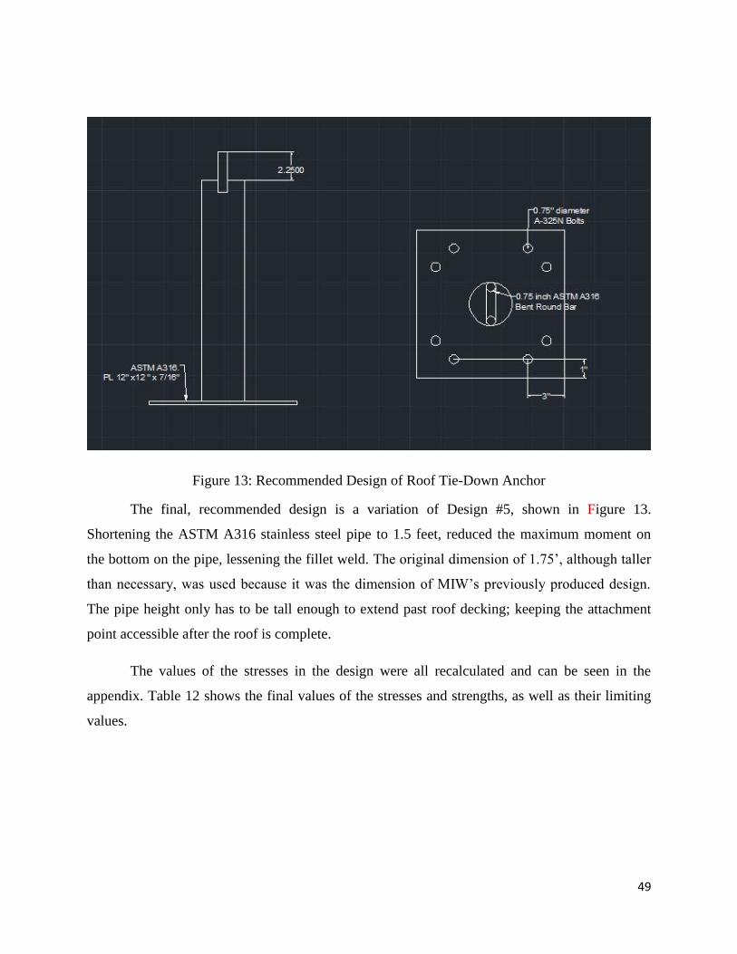
Figure 13: Recommended Design of Roof Tie-Down Anchor
The final, recommended design is a variation of Design #5, shown in Figure 13.
Shortening the ASTM A316 stainless steel pipe to 1.5 feet, reduced the maximum moment on
the bottom on the pipe, lessening the fillet weld. The original dimension of 1.75’, although taller
than necessary, was used because it was the dimension of MIW’s previously produced design.
The pipe height only has to be tall enough to extend past roof decking; keeping the attachment
point accessible after the roof is complete.
The values of the stresses in the design were all recalculated and can be seen in the
appendix. Table 12 shows the final values of the stresses and strengths, as well as their limiting
values.

50
Table 13: Table of stress values and the corresponding limits calculated for the final design
Bent Bar: Max Values Limits:
Axial Stress (ksi) Bending Stress (ksi) Axial + Bending (ksi) Strength (ksi)
0.213 24.198 24.412 37.5
Φ = 0.75
Shear Stress (ksi)
Flexural Shear Strength
(ksi)
0.006
27
Φ = 0.9
Pipe: Ultimate Limits:
Axial Stress (ksi) Bending Stress (ksi) Axial + Bending (ksi) Strength (ksi)
1.66 40.89 42.55 52.5
Φ = 0.75
Shear Stress (ksi)
Flexural Shear Strength
(ksi)
1.65
45.4
Φ = 0.9
Pipe: Yield
Axial Stress (ksi) Bending Stress (ksi) Axial + Bending (ksi) Strength (ksi)
0.597 14.72 15.32
27
Φ = 0.9
Shear Stress (ksi)
Flexural Shear Strength
(ksi)
0.596
16.2
Φ = 0.9
Slenderness Ratio
D/t 0.07E/Fy
3.89 65.3
51
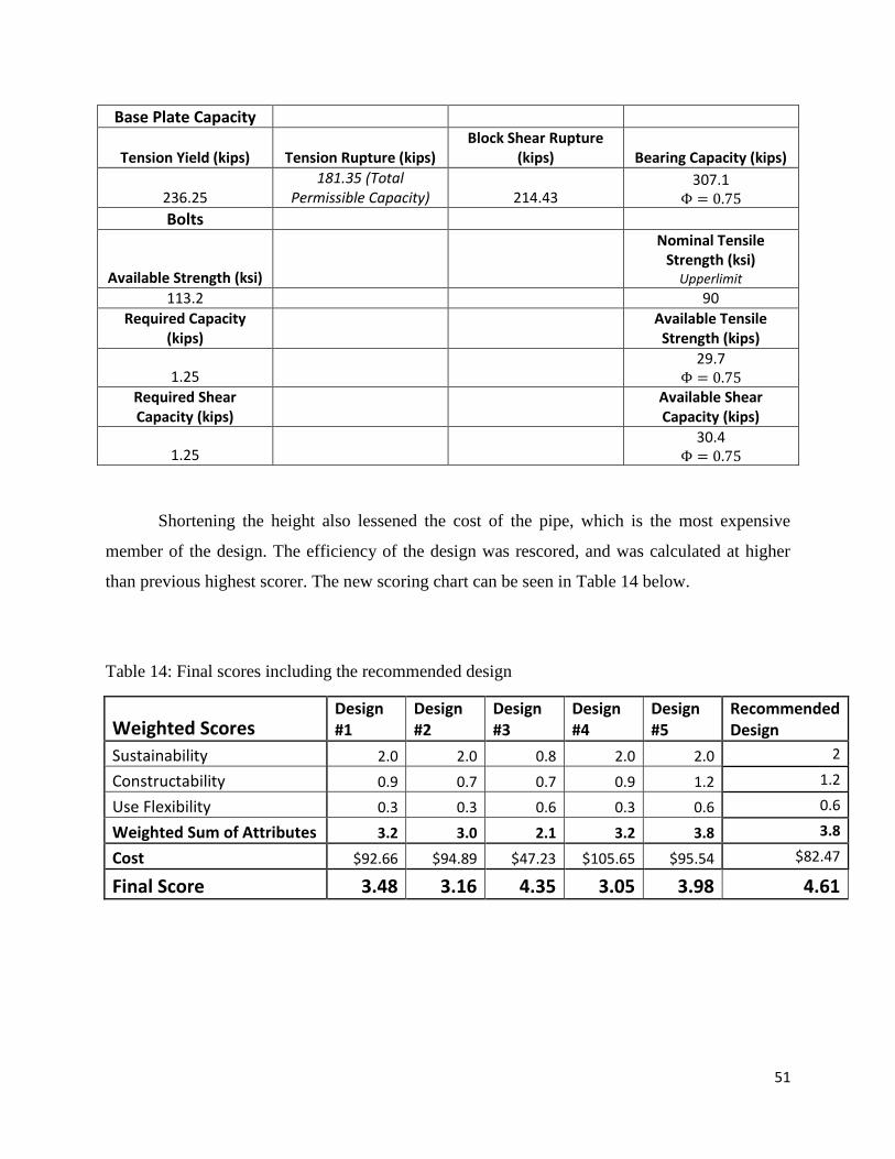
Base Plate Capacity
Tension Yield (kips) Tension Rupture (kips) Block Shear Rupture
(kips) Bearing Capacity (kips)
236.25 181.35 (Total
Permissible Capacity) 214.43 307.1
Φ = 0.75
Bolts
Available Strength (ksi)
Nominal Tensile Strength (ksi)
Upperlimit 113.2 90
Required Capacity (kips)
Available Tensile Strength (kips)
1.25 29.7
Φ = 0.75 Required Shear Capacity (kips)
Available Shear Capacity (kips)
1.25 30.4
Φ = 0.75
Shortening the height also lessened the cost of the pipe, which is the most expensive
member of the design. The efficiency of the design was rescored, and was calculated at higher
than previous highest scorer. The new scoring chart can be seen in Table 14 below.
Table 14: Final scores including the recommended design
Weighted Scores Design #1
Design #2
Design #3
Design #4
Design #5
Recommended Design
Sustainability 2.0 2.0 0.8 2.0 2.0 2
Constructability 0.9 0.7 0.7 0.9 1.2 1.2
Use Flexibility 0.3 0.3 0.6 0.3 0.6 0.6
Weighted Sum of Attributes 3.2 3.0 2.1 3.2 3.8 3.8
Cost $92.66 $94.89 $47.23 $105.65 $95.54 $82.47
Final Score 3.48 3.16 4.35 3.05 3.98 4.61
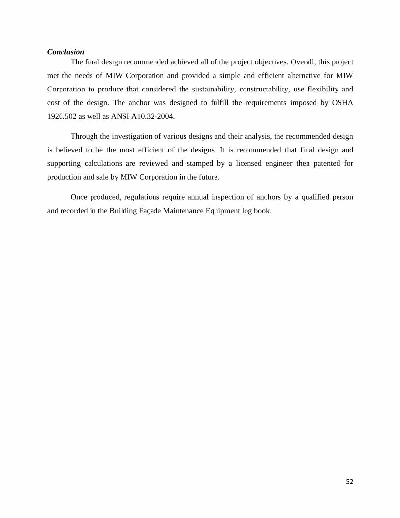
52
Conclusion
The final design recommended achieved all of the project objectives. Overall, this project
met the needs of MIW Corporation and provided a simple and efficient alternative for MIW
Corporation to produce that considered the sustainability, constructability, use flexibility and
cost of the design. The anchor was designed to fulfill the requirements imposed by OSHA
1926.502 as well as ANSI A10.32-2004.
Through the investigation of various designs and their analysis, the recommended design
is believed to be the most efficient of the designs. It is recommended that final design and
supporting calculations are reviewed and stamped by a licensed engineer then patented for
production and sale by MIW Corporation in the future.
Once produced, regulations require annual inspection of anchors by a qualified person
and recorded in the Building Façade Maintenance Equipment log book.

53
References
AISC (2013). Steel Construction Manual, 14th Edition, American Institute of Steel Construction.
Alberta. “OHS Code Explanation Guide: Section 151 Clearance, maximum arresting force and
swing.” <http://work.alberta.ca/searchaarc/603.html> (July 23, 2015.)
ASCE (2006.) Code of Ethics. <http://www.asce.org/code-of-ethics/> (May 24 2015.)
American Institute of Steel Construction. (2015). “Benefits of Certification.”
<https://www.aisc.org/content.aspx?id=32098> (May 24, 2015.)
ASSE. ANSI/ASSE Z359 Protection Code (Version 3.0). The American Society of Safety
Engineers. (June 6, 2015)
ANSI. (n.d.) “About ANSI.”
<http://www.ansi.org/about_ansi/overview/overview.aspx?menuid=1> (June 24 2015.)
ANSI. (April 25, 2013.) “Maximum Arresting Force.” Rigid Lifelines.
<http://www.rigidlifelines.com/blog/entry/maximum-arresting-force> (June 24, 2015.)
ASTM International. (n.d.) “Standard Specification for Seamless and Welded Austenitic
Stainless Steel Pipes” < http://www.ussa.su/_/89/ASTM_A312.PDF> (June 6, 2015.)
Fall Protection USA. (2015.) “Selected OSHA Fall Protecting.”
<http://www.fallprotectionusa.com/osha_fall_regulations.html > (May 24 2015.)
Flexible Lifeline Systems. (n.d.) “Through-Bolt Tieback Anchors.” < http://www.fall-
arrest.com/literature/through_bolt_tieback_anchor.pdf>
Flexible Lifeline Systems. (n.d.) “Tieback Anchors: Roof Anchors For Fall Protection And
Façade Access” <http://www.fall-arrest.com/industries/building-maintenance/tieback-
anchors/> (June 6, 2015).
Hibbeler, Russell C. (2010). Mechanics of Materials, Eighth Edition, Prentice Hall.
The International Safety Equipment Association. (n.d.) “Frequently Addressed Topics in Fall
Protection.”
<https://www.safetyequipment.org/userfiles/File/Fall_Protection/fall_protection_topics.p
df>
MacDonald, C. (2011). “OSHA Changes the Rules.” Roofing Contractor.
<http://www.roofingcontractor.com/articles/87678-osha-changes-the-rules> (May 24
2015.)
McCormac, Jack C. (2011). Structural Steel Design, Fifth Edition., Prentice Hall.

54
McGeorge, D., and Palmer, A. (2009). Construction Management: New Directions, Wiley, New
York.
MIW Corporation. (n.d.) “Welcome.” <http://www.miwcorporation.com/> (May 24, 2015.)
National Society of Professional Engineers. (2015.) “Licensure.”
<http://www.nspe.org/resources/licensure/what-pe> (June 8, 2015.)
NCEES. (n.d.) “Licensure.” <http://ncees.org/licensure/> (June 10, 2015.)
Occupational Safety & Health Administration [OSHA]. (n.d.). Regulations (Standards-29 CFR).
<http://www.osha.gov/pls/oshaweb/owasrch.search_form?p_do
c_type=STANDARDS&p_toc_level=1&p_keyvalue=24>
OSHA. (n.d.) “About OSHA.” <https://www.osha.gov/about.html > (May 24, 2015.)
RISA. (2015.) “RISA 3D” <https://risa.com/p_risa3d.html> (July 18, 2015.)
Simplified Safety (n.d.). “Anchor Points” < http://simplifiedsafety.com/store/fall-
protection/anchor-points.html> (July 23, 2015.)
U.S. Green Building Council. (March 15, 2015) “About LEED.”
<http://www.usgbc.org/articles/about-leed> (July 1, 2015).
U.S. Green Building Council. (n.d.) “LEED: Materials and Resources (MR).”
<http://www.usgbc.org/credits/new-construction/v4/material-%26-resources> (July 1,
2015).
Wenzel Metal Spinning. (n.d.) “Galvanized vs Stainless Steel- Cost, Strength and Weight
Differences” < http://www.wenzelmetalspinning.com/galvanized-steel-vs-stainless.html>
(June 15, 2015.)

55
Appendices
Appendices A: Project Proposal

56
57

58
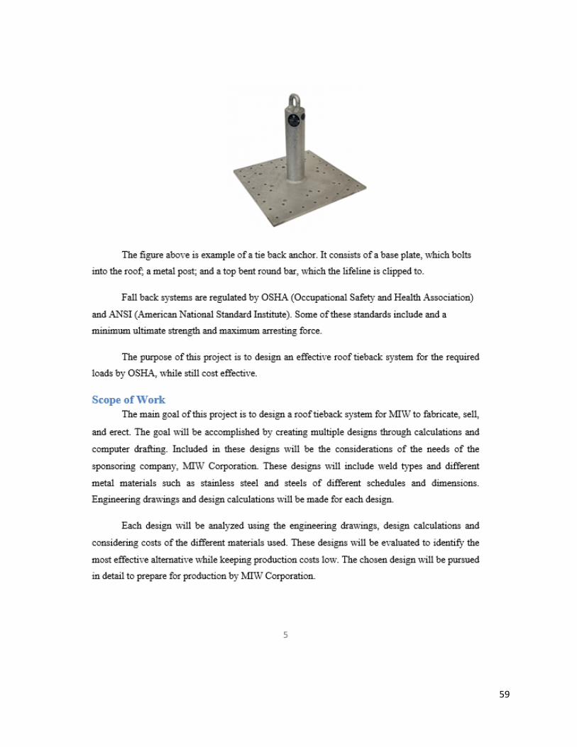
59

60

61
62

63

64

65
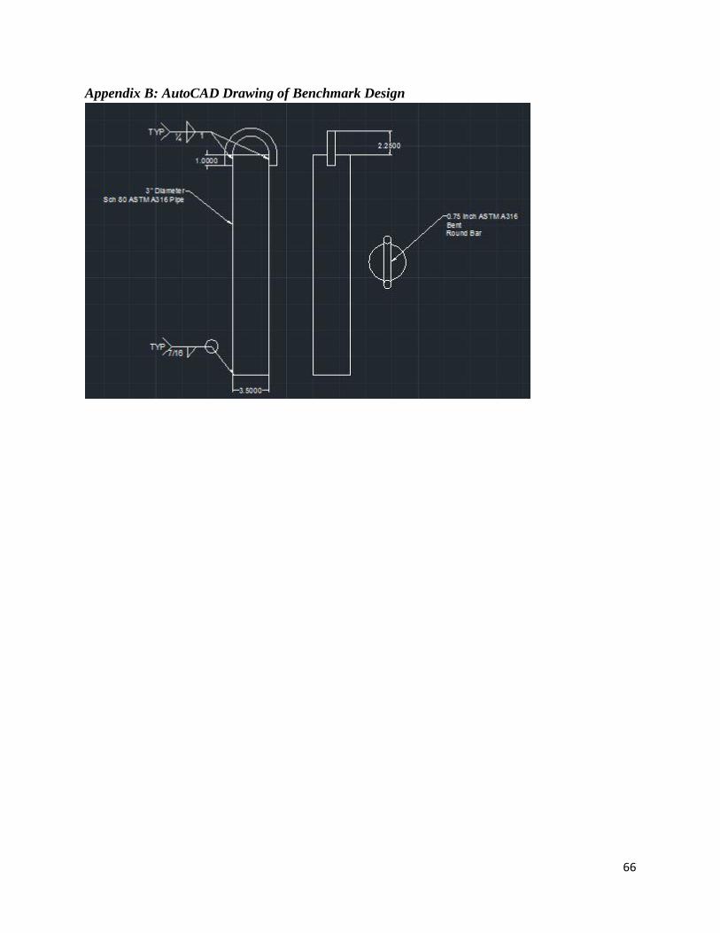
66
Appendix B: AutoCAD Drawing of Benchmark Design
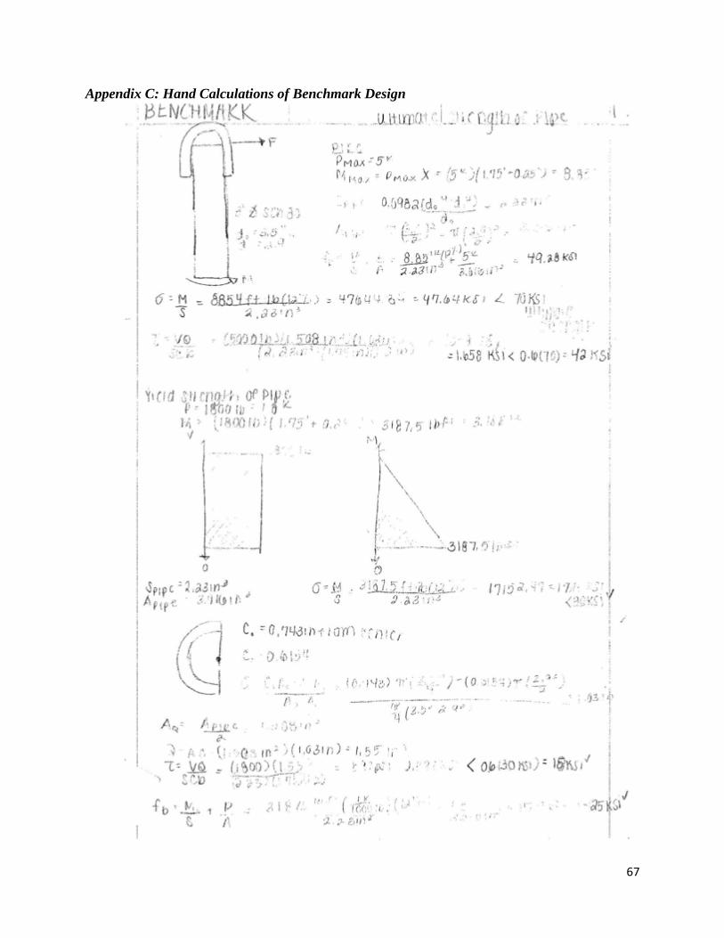
67
Appendix C: Hand Calculations of Benchmark Design
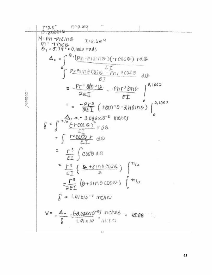
68

69
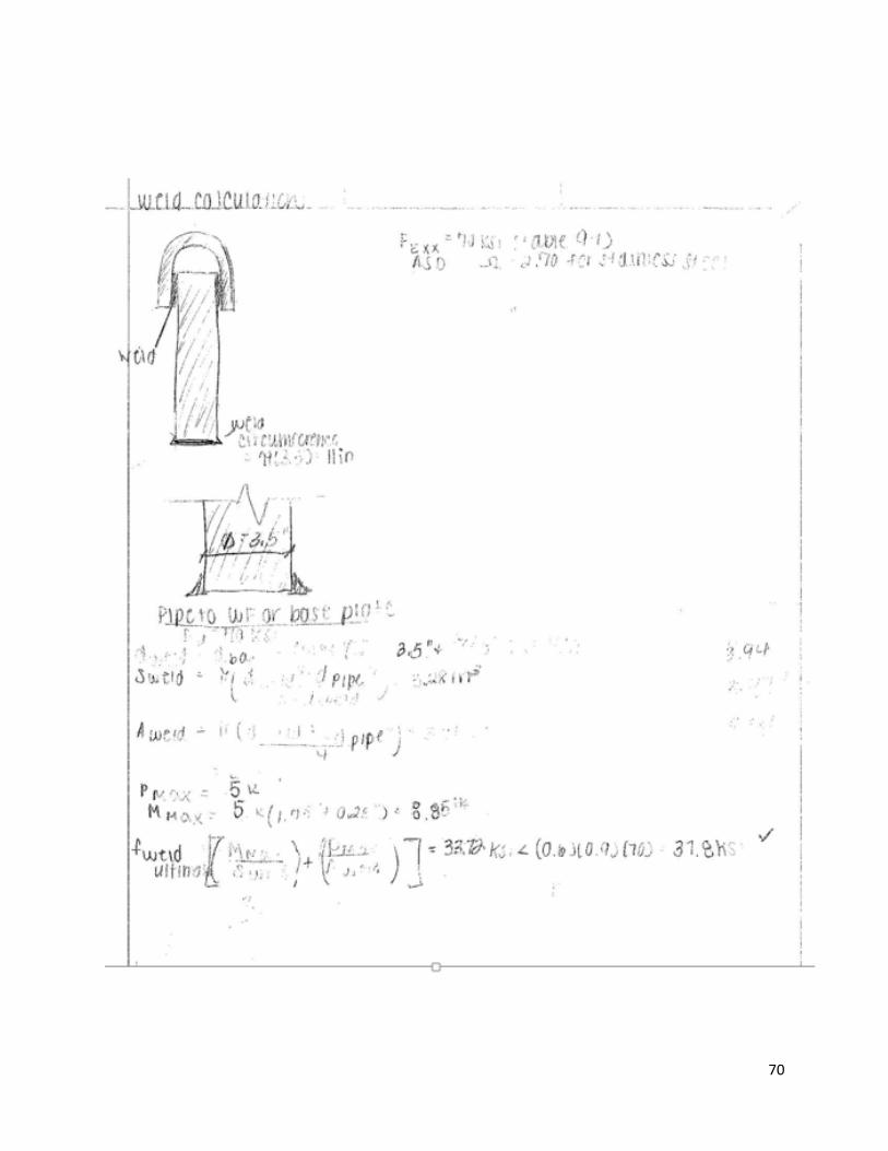
70
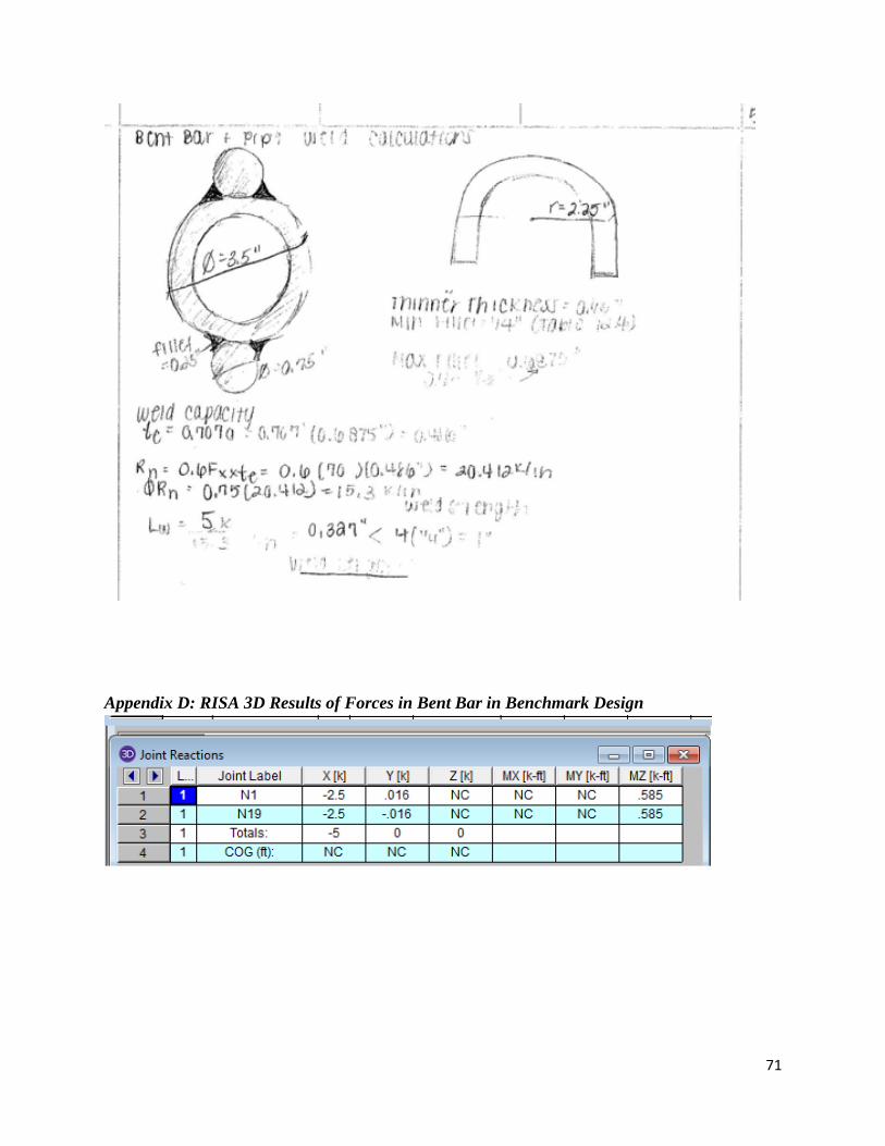
71
Appendix D: RISA 3D Results of Forces in Bent Bar in Benchmark Design
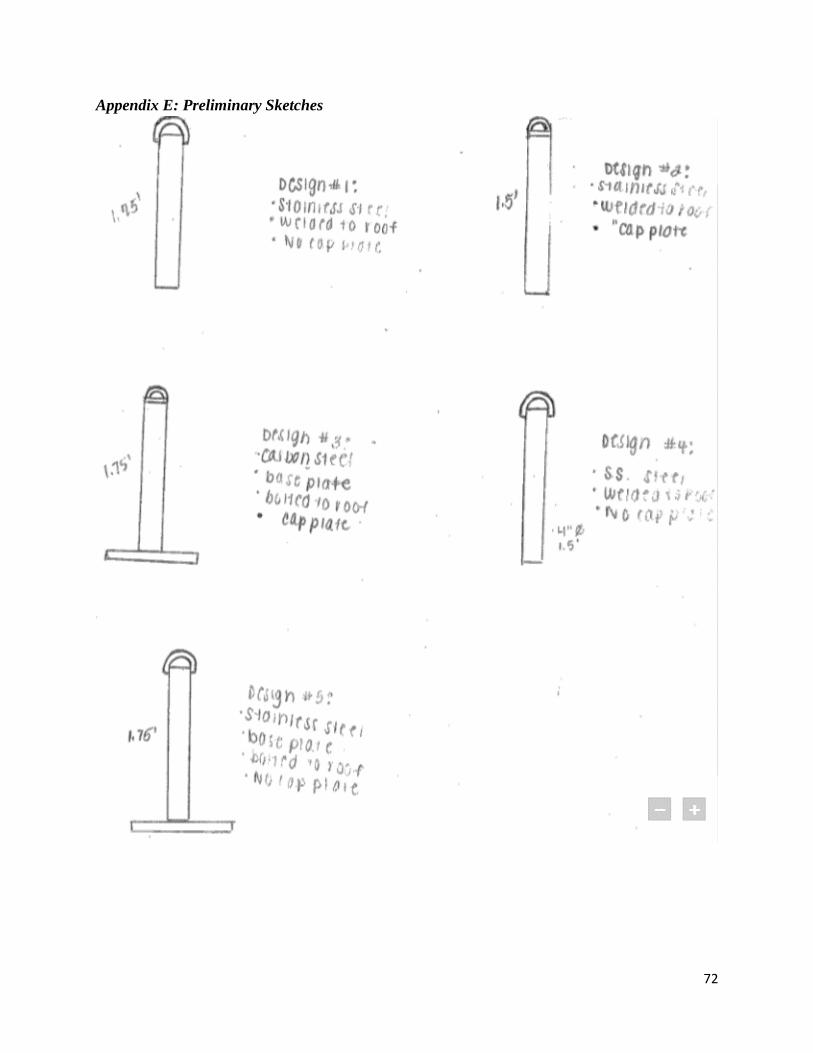
72
Appendix E: Preliminary Sketches

73
Appendix F: Hand Calculations of Design #2

74
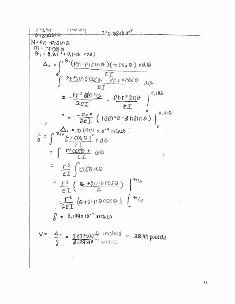
75
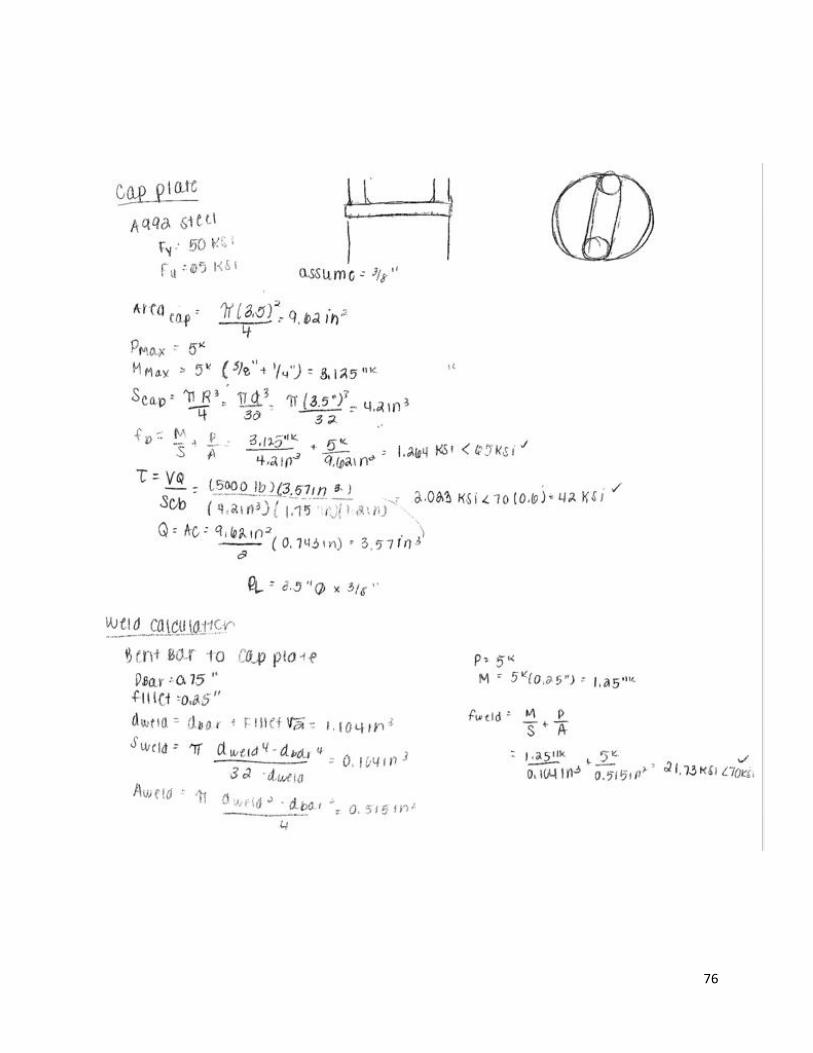
76

77
Appendix G: Hand Calculations of Design #3

78

79
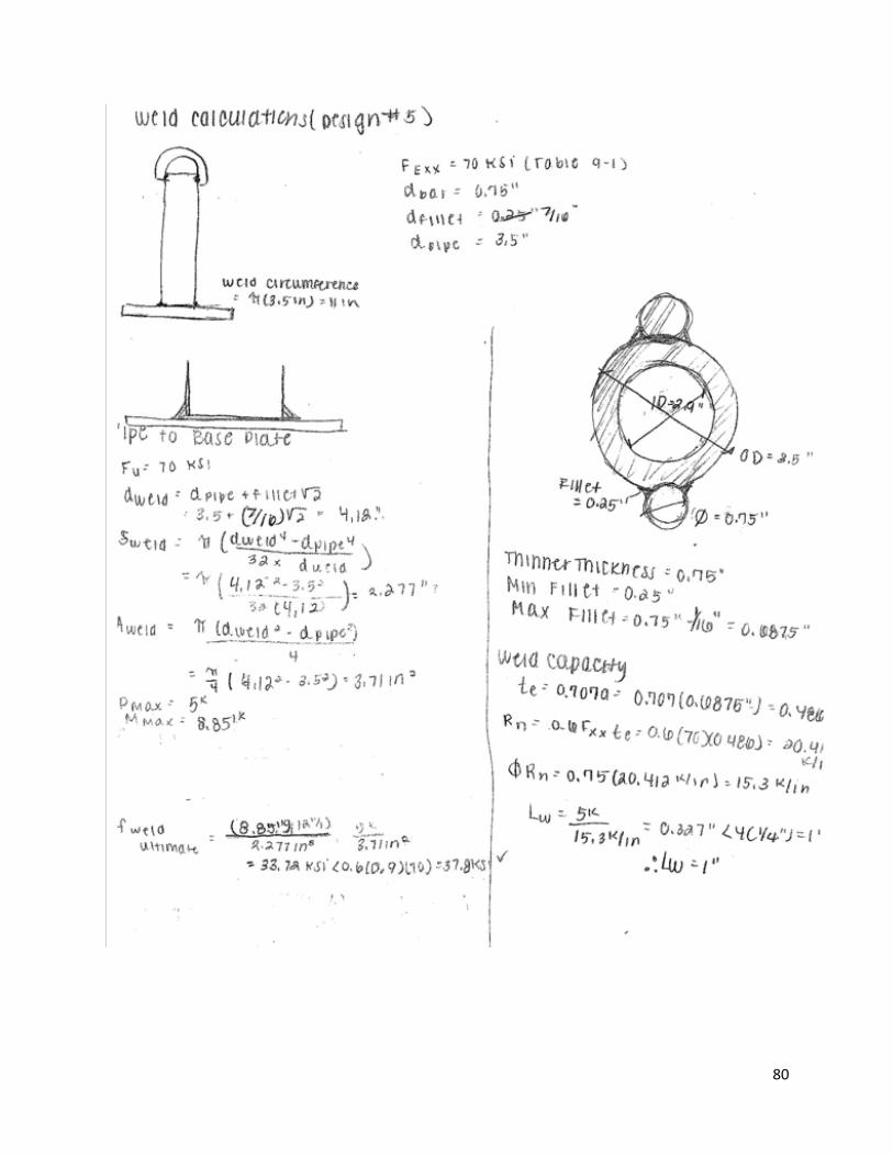
80

81

82
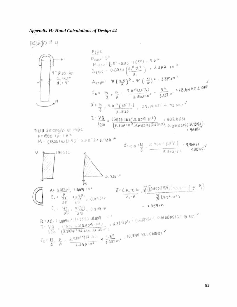
83
Appendix H: Hand Calculations of Design #4
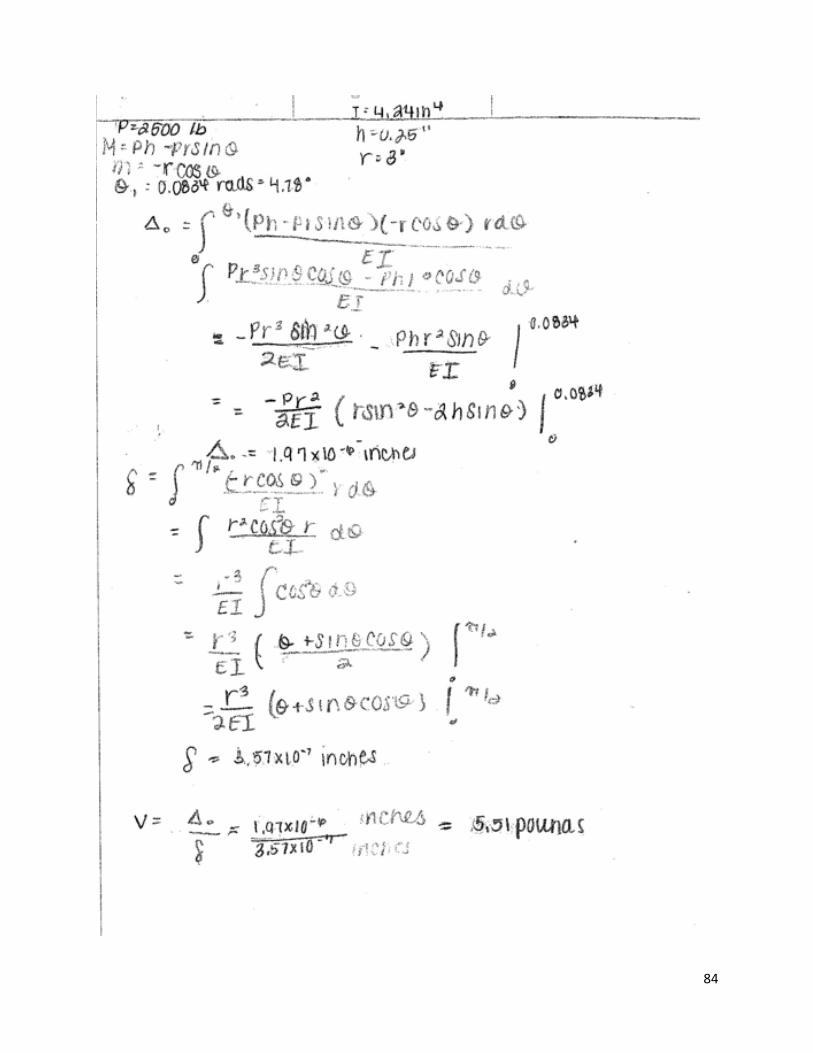
84

85

86
Appendix I: Hand Calculations of Design #5
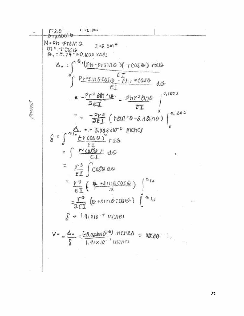
87

88
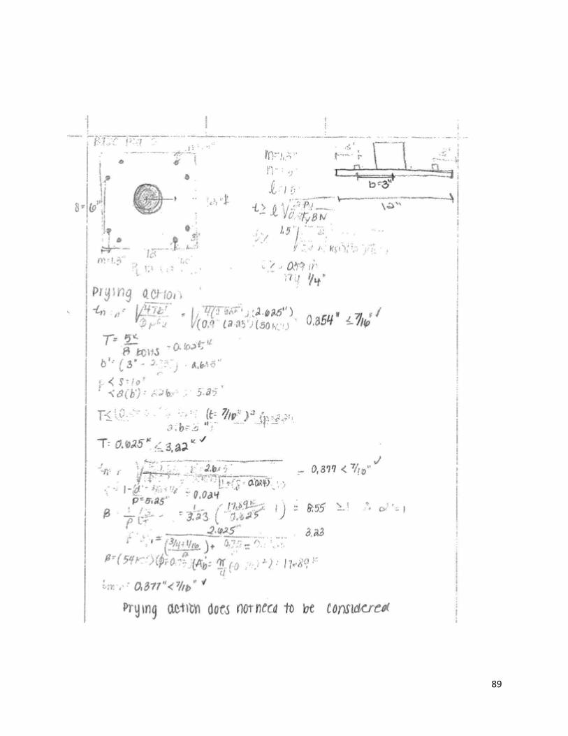
89
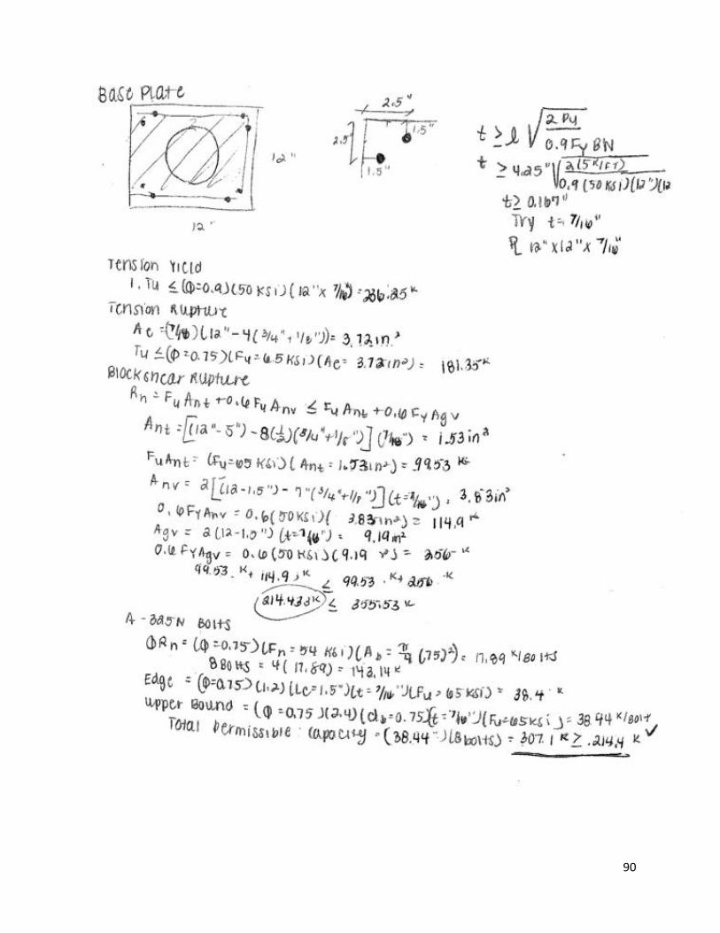
90
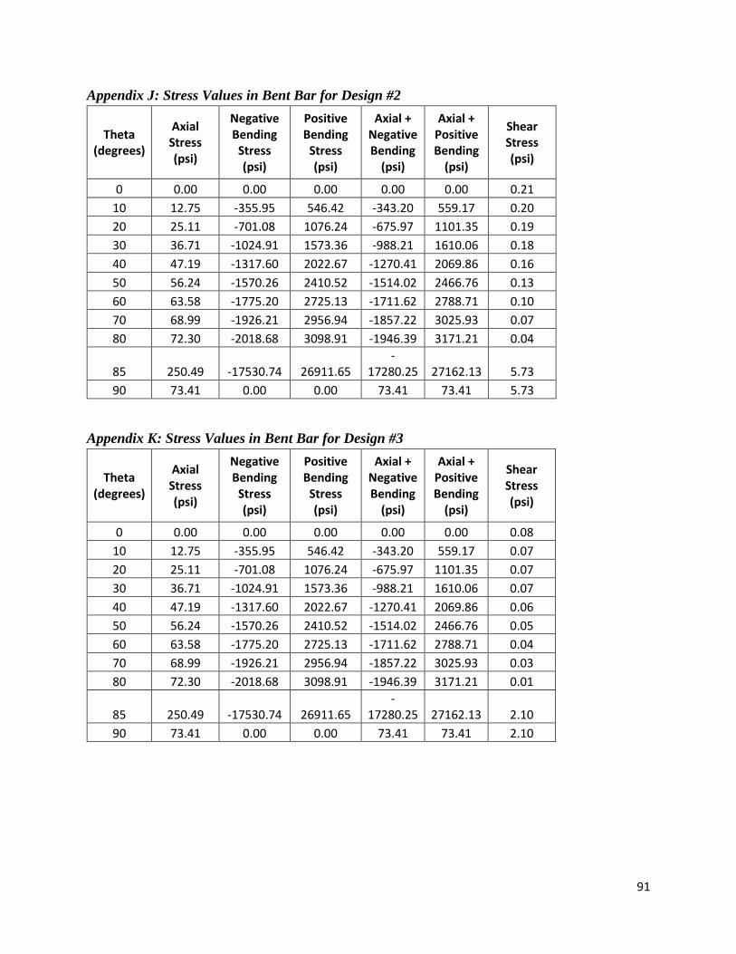
91
Appendix J: Stress Values in Bent Bar for Design #2
Theta (degrees)
Axial Stress (psi)
Negative Bending
Stress (psi)
Positive Bending
Stress (psi)
Axial + Negative Bending
(psi)
Axial + Positive Bending
(psi)
Shear Stress (psi)
0 0.00 0.00 0.00 0.00 0.00 0.21
10 12.75 -355.95 546.42 -343.20 559.17 0.20
20 25.11 -701.08 1076.24 -675.97 1101.35 0.19
30 36.71 -1024.91 1573.36 -988.21 1610.06 0.18
40 47.19 -1317.60 2022.67 -1270.41 2069.86 0.16
50 56.24 -1570.26 2410.52 -1514.02 2466.76 0.13
60 63.58 -1775.20 2725.13 -1711.62 2788.71 0.10
70 68.99 -1926.21 2956.94 -1857.22 3025.93 0.07
80 72.30 -2018.68 3098.91 -1946.39 3171.21 0.04
85 250.49 -17530.74 26911.65 -
17280.25 27162.13 5.73
90 73.41 0.00 0.00 73.41 73.41 5.73
Appendix K: Stress Values in Bent Bar for Design #3
Theta (degrees)
Axial Stress (psi)
Negative Bending
Stress (psi)
Positive Bending
Stress (psi)
Axial + Negative Bending
(psi)
Axial + Positive Bending
(psi)
Shear Stress (psi)
0 0.00 0.00 0.00 0.00 0.00 0.08
10 12.75 -355.95 546.42 -343.20 559.17 0.07
20 25.11 -701.08 1076.24 -675.97 1101.35 0.07
30 36.71 -1024.91 1573.36 -988.21 1610.06 0.07
40 47.19 -1317.60 2022.67 -1270.41 2069.86 0.06
50 56.24 -1570.26 2410.52 -1514.02 2466.76 0.05
60 63.58 -1775.20 2725.13 -1711.62 2788.71 0.04
70 68.99 -1926.21 2956.94 -1857.22 3025.93 0.03
80 72.30 -2018.68 3098.91 -1946.39 3171.21 0.01
85 250.49 -17530.74 26911.65 -
17280.25 27162.13 2.10
90 73.41 0.00 0.00 73.41 73.41 2.10

92
Appendix L: Stress Values in Bent Bar for Design #4
Theta (degrees)
Axial Stress (psi)
Negative Bending
Stress (psi)
Positive Bending
Stress (psi)
Axial + Negative Bending
(psi)
Axial + Positive Bending
(psi)
Shear Stress (psi)
0 0.00 0.00 0.00 0.00 0.00 0.00
10 2.16 -70.77 93.68 -68.60 95.84 0.00
20 4.26 -139.39 184.51 -135.13 188.77 0.00
30 6.23 -203.77 269.74 -197.54 275.97 0.00
40 8.01 -261.96 346.77 -253.95 354.78 0.00
50 9.54 -312.19 413.27 -302.65 422.81 0.00
60 10.79 -352.94 467.21 -342.15 477.99 0.00
70 11.71 -382.96 506.95 -371.25 518.65 0.00
80 12.27 -401.35 531.29 -389.08 543.56 0.00
85 189.76 -20539.09 27188.90 -
20349.32 27378.66 0.36
90 12.46 0.00 0.00 12.46 12.46 0.36
Appendix M: Stress Values in Bent Bar for Design #5
Theta (degrees)
Axial Stress (psi)
Negative Bending
Stress (psi)
Positive Bending
Stress (psi)
Axial + Negative Bending
(psi)
Axial + Positive Bending
(psi)
Shear Stress (psi)
0 0.00 0.00 0.00 0.00 0.00 0.01
10 6.23 -169.96 224.99 -163.73 231.23 0.01
20 12.28 -334.76 443.15 -322.48 455.43 0.01
30 17.95 -489.39 647.84 -471.44 665.79 0.01
40 23.08 -629.15 832.84 -606.07 855.92 0.00
50 27.50 -749.79 992.54 -722.28 1020.05 0.00
60 31.09 -847.65 1122.09 -816.55 1153.18 0.00
70 33.74 -919.75 1217.53 -886.01 1251.27 0.00
80 35.36 -963.91 1275.99 -928.55 1311.35 0.00
85 213.12 -18280.00 24198.41 -
18066.89 24411.53 0.36
90 35.90 0.00 0.00 35.90 35.90 0.36
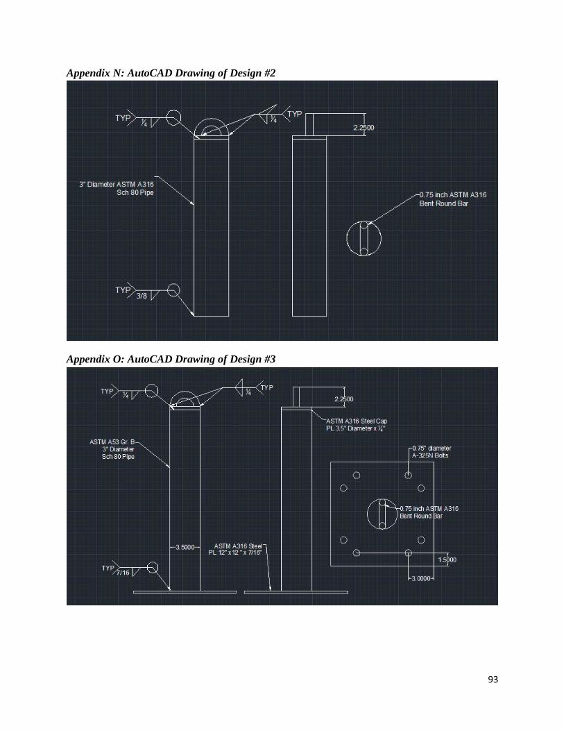
93
Appendix N: AutoCAD Drawing of Design #2
Appendix O: AutoCAD Drawing of Design #3
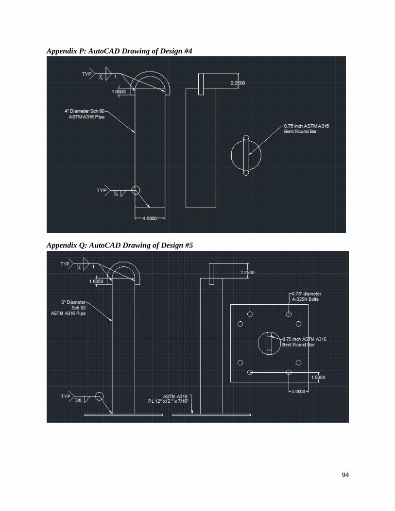
94
Appendix P: AutoCAD Drawing of Design #4
Appendix Q: AutoCAD Drawing of Design #5
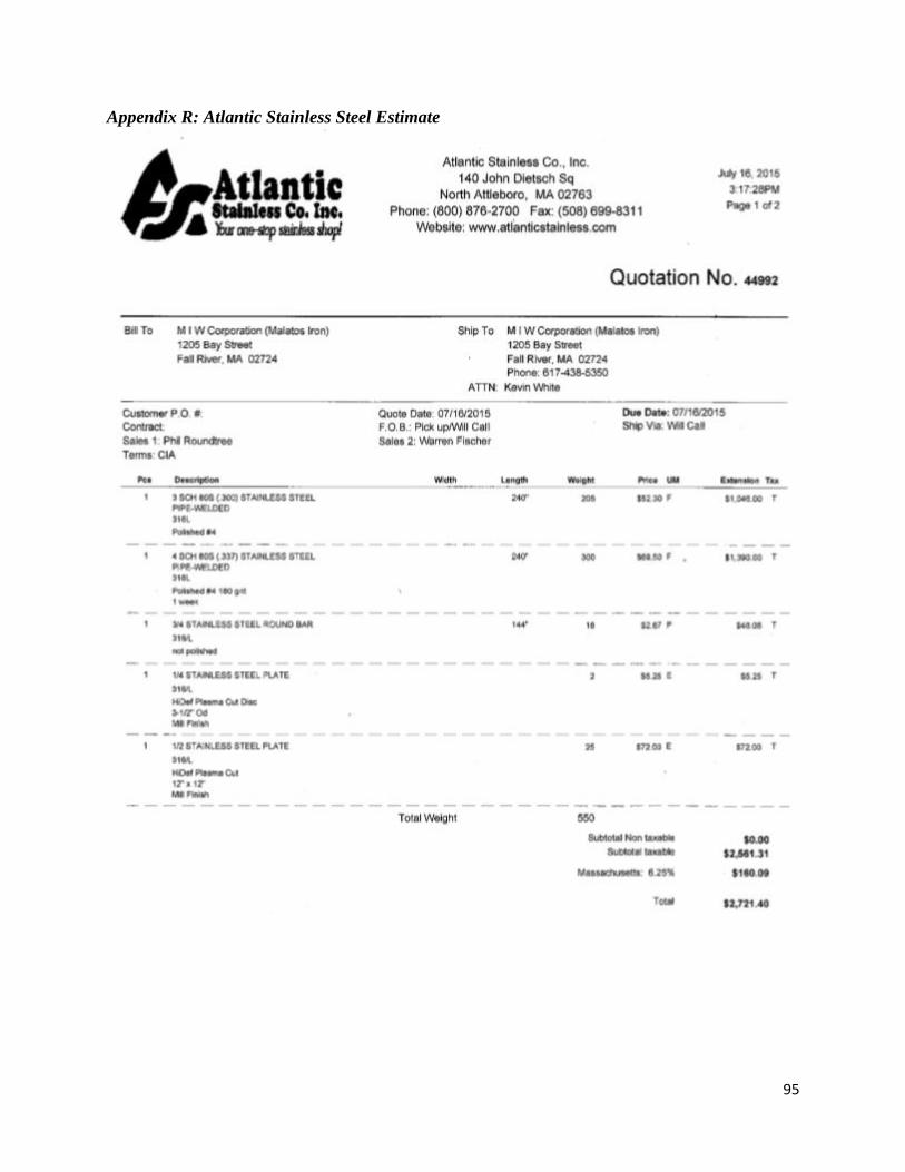
95
Appendix R: Atlantic Stainless Steel Estimate
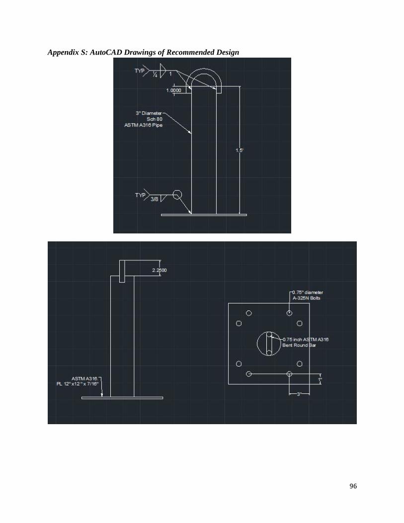
96
Appendix S: AutoCAD Drawings of Recommended Design
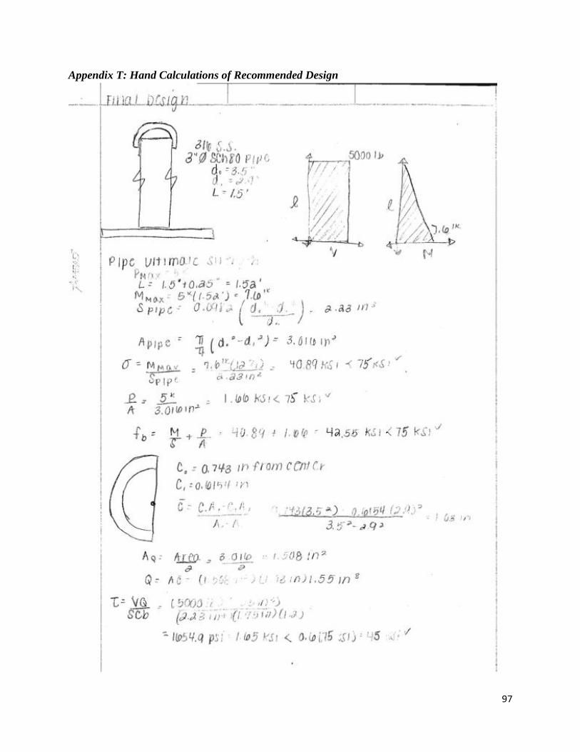
97
Appendix T: Hand Calculations of Recommended Design
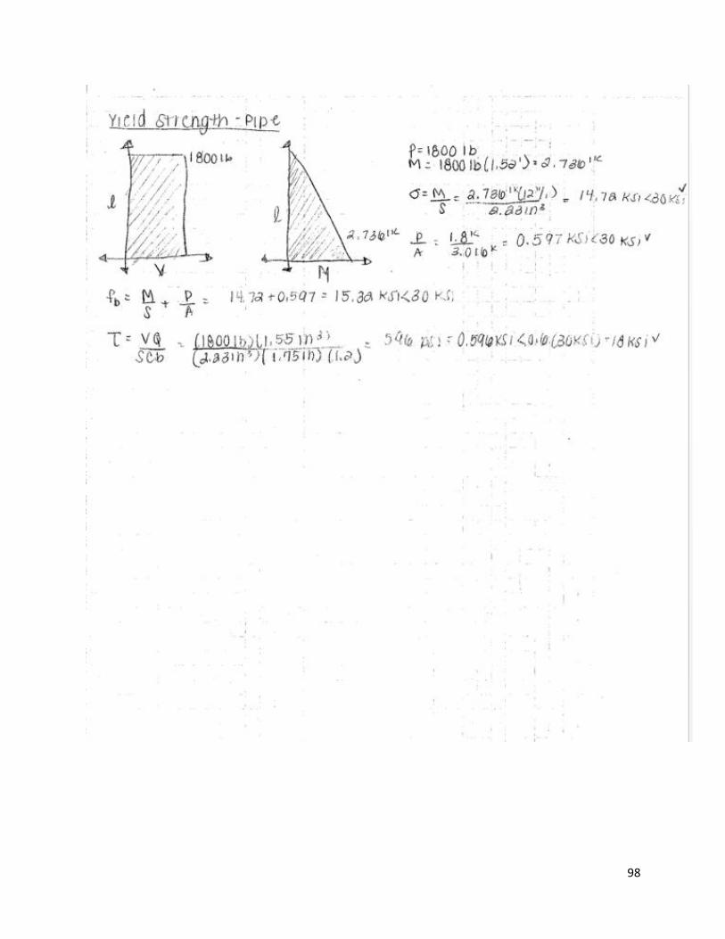
98

99

100
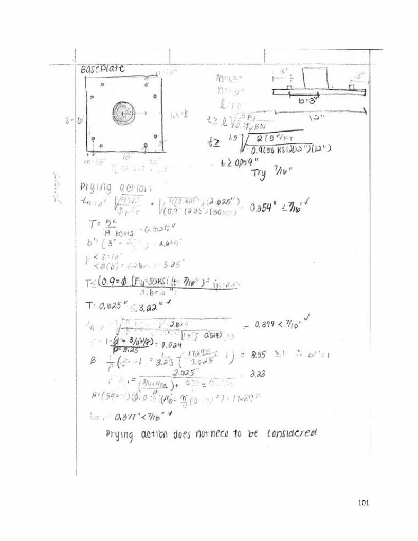
101

102

103
Appendix U: Stress Values in Bent Bar for Recommended Design
Theta (degrees)
Axial Stress (psi)
Negative Bending
Stress (psi)
Positive Bending
Stress (psi)
Axial + Negative Bending
(psi)
Axial + Positive Bending
(psi)
Shear Stress (psi)
0 0.00 0.00 0.00 0.00 0.00 0.10
10 6.23 -169.96 224.99 -163.73 231.23 0.10
20 12.28 -334.76 443.15 -322.48 455.43 0.10
30 17.95 -489.39 647.84 -471.44 665.79 0.09
40 23.08 -629.15 832.84 -606.07 855.92 0.08
50 27.50 -749.79 992.54 -722.28 1020.05 0.07
60 31.09 -847.65 1122.09 -816.55 1153.18 0.05
70 33.74 -919.75 1217.53 -886.01 1251.27 0.03
80 35.36 -963.91 1275.99 -928.55 1311.35 0.02
85 213.12 -18280.00 24198.41 -
18066.89 24411.53 5.72
90 35.90 0.00 0.00 35.90 35.90 5.73