Exploring underwater target detection by imaging polarimetry and

DESIGNOFACOMPACTUNDERWATERIMAGINGANDGEOLOCALIZATIONPLATFORM
WITHEDGECOMPUTINGCAPABILITY
By
ZuodongLiang
SeniorThesisinComputerEngineering
UniversityofIllinoisatUrbana-Champaign
Advisor:ProfessorViktorGruev
May2020
©2020,ZuodongLiang

ii
AbstractWithitsendlessdarkbluetone,theunderwaterworldisfilledwithcolor,life,andbeauty.Ithasmany
scientific imaging research opportunities. However, during the development of an underwater
geolocation instrument based on polarization imaging sensors, we noticed that the underwater
devicesarealldesignedforcinematographyapplications.Theyarebulkyandcomplicated,andthey
cannotsatisfytheever-changingscientificresearchneeds.Inthisthesis,wereportonthedesignofa
compact,expandableunderwateredgecomputingplatformbasedontheNvidiaJetsondevices.This
platformiscapableofrecordingandprocessingmorethan4hoursoffootageunderwater.Withits
modulardesign,theplatformcansupportimagesensorsupto70mm/2.75"diagonalandvirtually
anylens.Thisplatformopensuppossibilitiesforresearcherstoperformunderwaterdatacollections,
real-timemachinelearninginferences,andmarinebiologystudies.
SubjectKeywords:polarization;imaging;underwaternavigation;edgecomputing

iii
AcknowledgmentsIthankmythesisadvisor,ProfessorViktorGruev,forallowingmetobeapartofhisresearchlab.His
patience,guidance,andimmenseknowledgehelpmetobecomeabetterengineer.
Ialsothankmyfamilyandmygirlfriendfortheircontinuoussupport.Itwastheirsupporthelpedme
getthroughallthechallengesIfaced.Theysharemytearsandjoyswithme.

iv
Contents1. Introduction........................................................................................................................................................................12. Motivations.........................................................................................................................................................................32.1. OverviewofPreviousDevices.........................................................................................................................32.2. GoalsforNewPlatform......................................................................................................................................4
3. MechanicalDesign...........................................................................................................................................................53.1. Overview...................................................................................................................................................................53.2. WaterTightness....................................................................................................................................................63.3. InternalArrangement.........................................................................................................................................83.3.1. PowerSubsystem............................................................................................................................................83.3.2. ProcessingSubsystem...................................................................................................................................93.3.3. ImagingSubsystem......................................................................................................................................103.3.4. UserInterface.................................................................................................................................................123.3.5. Interconnect....................................................................................................................................................13
3.4. ThermalDesign...................................................................................................................................................143.5. ExpansionandUpgrade..................................................................................................................................143.5.1. ExternalExpansion......................................................................................................................................143.5.2. UnderwaterConnection............................................................................................................................153.5.3. InternalUpgrade...........................................................................................................................................15
4. ElectricalDesign............................................................................................................................................................164.1. Overview................................................................................................................................................................164.2. ExpansionUseCases........................................................................................................................................184.2.1. CameraandImagerConfiguration........................................................................................................184.2.2. ExternalModule............................................................................................................................................194.2.3. ExternalMonitor...........................................................................................................................................194.2.4. ContinuousRecording................................................................................................................................204.2.5. UnderwaterPanoramic..............................................................................................................................20
5. ConclusionandFutureWork...................................................................................................................................23References..................................................................................................................................................................................24AppendixA.ProcessingSystemComparisons............................................................................................................26

1
1. IntroductionNowadays,weallhavesmartphones.Theembeddedglobalpositioningsystem(GPS)receptioninside
our smartphones has significantly simplified our lives by providing accurate geolocalization
informationtous.However,whenweareunderwater,theGPScannotprovidereliableservicedue
tothehighreflectivityofthewater-airboundaryandthehighelectromagneticlossesunderwater[1].
Nevertheless,geolocationiscriticalformanyunderwateractivities,forexamplesubmarines.Modern
submarines are equipped with multiple geolocalization and navigation instruments, and two
commonlyusedsystemsareactivesoundnavigationranging(SONAR)andinertialnavigationsystem
(INS).However,eachsystemhasitslimitationsanddrawbacks.ActiveSONARwillrequiredetailed
hydrographic data; hence it can only be used in the charted area and often is further limited to
friendlywatersasitcanbedetectedandtrackedbyanenemy[2].INSisasystemthatcalculatesthe
locationbaseonaknowninitialstateandintegrationofmovements.However,INSusuallysuffers
fromunboundederrorsduetosensornoiseanddrift,causinggeolocalizationerrorsovertime[3].
Hence,INSrequiresfrequentcalibrationbyGPSorotheraccurategeolocalizationsystems[4].
Humans developed SONAR technology by learning how bats navigate with their echolocation
capability[5].Similarlybioinspired,wehaveturnedourfocustothemantisshrimp,acrustaceanthat
isknownforitsuniquevisionsystemthatiscapableofsensingthepolarizationoflight[6].Studies
haveshownthatmanymarineanimals, includingmantisshrimp,areusingpolarizationvisionfor
communication,preydetection,andpotentiallyfornavigation[7].
Inpreviousworks,researcherswereabletodevelopapolarizationimagingsensorandintegrateit
intoacamera.Thentheymodifiedanunderwatercinematographysystemtoperformunderwater
geolocalizationtasksbasedoncelestialpolarizedlight.Usingthissystem,theyprovedthefeasibility
ofusingpolarizationforunderwatergeolocalizationandnavigationandachievedanaverageof61
kmofaccuracy[8,9].
Machinelearninghasbenefitedmanyindustriesinrecentyears.Itisalsoconsideredtobeafeasible
method for further improving the accuracy of polarization-based underwater geolocalization.
However, suchamethodwill require a large amountof real-worlddata tohelp the algorithm to
"learn" the features presented in celestial polarization images. The current underwater data
collectiondevicewasnotdesignedforresearch,anditposesmanychallengesanddangersformass
datacollection.
This thesis reports on the design of a compact, modular, and expandable underwater research
platformthatcansuitdatacollectionandresearchneeds.Chapter2analyzestheissueswithseveral

2
current underwater data collection devices and proposes the design goals for the newplatform.
Chapter3and4discussesthemechanicalandelectricaldesignofthenewplatformindetail.Finally,
chapter5explainsthecurrentprogressandfutureworkofthisproject.

3
2. Motivations2.1. OverviewofPreviousDevicesPowell [9] describes the first-generation underwater geolocalization system. The system was
modifiedbaseon a Light andMotionBluefinVX2000underwaterhousing thatwasdesigned for
camcorders.AnAquatica4-inchunderwaterglassdomeportwasattachedtothehousingtoensure
high-qualityimages.AcustomCCDcamerawasusedtosensethepolarizationinformation,andaPNI
TCM-MBelectroniccompassmodulewasusedtorecordthedevice'sgestureandheading.AnADL
Single-Board Computer (SBC) with 2nd generation Intel Core-i7 processor was used for system
control and data logging. This computer provided enough computation power to record the
uncompressed image data to a solid-state drive at around 20MB/swhile streaming a real-time
previewtotheunderwatermonitor.ThisdevicecouldaccommodatealargeCanonzoomlensandan
81.4Whbatterypack,allowingthedevicetooperateforaround2hours.
Laterthisdevicewasupgradedbytheauthorandhiscolleaguetoaccommodateanewerimaging
subsystem.ThenewimagingsubsystemutilizesaFLIRBFS-U3-51S5P-Cmachinevisioncamera.This
camera contains a Sony IMX250-MZR 5.0 MP polarized monochrome sensor. A Fujinon
FE185C057HA-1185° field-of-view fish-eye lenswasused tocollect thecelestial image.Thenew
imagingsubsystemwillnowproducearound150MB/sofuncompressedimagedata.Toaddressthis
higherthroughput,theauthorupgradedtheprocessingunittoanADL120SSBCwitha6thgeneration
IntelCore-i7processor.Thefinaldevicemeasuresabout40cmlong,25cmwide,and30cmtall.The
underwaterhousingandunderwatermonitorassemblyweigharound15kg.When traveling, the
complete device and accessories were put into a heavy-duty case, causing the final weight to
approach30kg.
SamuelPowelllaterjoinedaresearchlabattheUniversityofQueensland,whereheandcolleagues
developedanewunderwaterdevicereportedin2019[10].ThisdevicewasbuiltwithinaNikonDSLR
underwaterhousingwitha6-inchdomeport.TheyutilizedanNvidiaJetsonTX1System-on-Module
(SoM) toperform thedata collection anddataprocessing tasksunderwater. Three Sony IMX219
image sensors and190° field-of-view fish-eye lenseswereused to createoverlappingpanoramic
imagesunderwater.Theywereabletoachievea4houroperationtimewiththisdevice.
Allthreeofthesedeviceswerebuilttoaccommodateunderwatercinematographyhousings.These
housingsarebuiltaroundaspecificcommercialcameraorcamcorder;hencetheyareverybulky,
anditishard,ifnotimpossible,tomodifythesehousingstofitresearchneeds.

4
2.2. GoalsforNewPlatformIn order to collectmore underwater celestial polarization images and prepare for the upcoming
machinelearningtasks,anewunderwaterresearchplatformwasproposedbytheauthor.
Thenewplatformneedstobecompact.Asthebuoyantforceisproportionaltothevolumeofthe
platform,havingacompactplatformalsomeansalightweightplatform.Duringseveralpreviousdata
collectiontrips,thecompletedeviceweighedaround30kg,makingtravelingwiththedevicecostly
anddifficult.
Thenewplatformalsoneedstosustainwaterpressure.Thegoal is todesignaplatformthatcan
sustain up to 50 meters of water pressure. Previous research has shown that polarization
informationcanbeobservedasdeepas200meters[11].However,duetotheauthor'sscubadiving
licenserestriction,hecanonlyreachasdeepas40meters.
Furthermore, thenewplatformneeds tosuit the imagingandgeolocalizationneeds.The imaging
subsystemneeds tobeable to accommodateawidevarietyof imagersand cameras.Theoptical
centerofthesensorshouldbepreciselyalignedtotheexteriorglassdomeport.Thegesture,location,
andtimedatawillbenecessaryformachinelearningtasks.Thesystemshouldincludeanintegrated
inertialmeasurementunit(IMU)tomeasurethegestureandtheheadingoftheplatform.Itshould
also integrate the GPS receiver to provide accurate time and ground truth geolocation to the
processingsubsystem.
Asascientificresearchplatform,thenewdeviceshouldbemodularandupgradable.Whenwemake
newdiscoveries,wemaychangeourdevicetoaddmoresensorsandrecordawidervarietyofdata.
Theolddeviceswereunable to fulfill ourever-changing researchneeds, and that isoneprimary
motivationforustodesignthisnewplatformfromscratch.
Thenewplatformalsoneedstohaveapowerfulprocessingunit.Itneedstobeabletoperformhigh-
throughputdatarecording,processing,andstreaming.Inthelongrun,italsoneedstoperformreal-
time inference of the machine learning model to demonstrate the geolocalization capability
underwater.

5
3. MechanicalDesignInordertofulfillalltherequirementsposedinthepreviouschapter,theauthorfirststartedwiththe
mechanicaldesignofthenewunderwaterresearchplatform.Thischapterintroducesthedesignby
providing an overviewof theplatform, and then explainsmultiple factors consideredduring the
designprocess.
3.1. OverviewAsshowninFigure1,thefinaldesigncanbedividedintothreecompartments:thecover,themain
housing,andthelenscompartment.
Duringtheunderwaterdatacollectionprocess,weneedtoadjusttheexposureoftheimagerandthe
headingofthedevice.Havinganunderwatermonitoriscrucialforperformingthistask.However,in
previousgenerationsoftheunderwatergeolocalizationdevices,wewereunabletointegratemonitor
intothedeviceduetotheconstructionofboththeunderwaterhousingandtheoff-the-shelfmonitor.
Havinganexternalunderwatermonitor forcesus tocarryanextra5 to10kgofweight,and the
danglingmonitorcableposeshazardsduringtheunderwaterdatacollectionprocess. In thisnew
platformdesign,theauthordecidedtointegrateamonitorintothehousing.Theauthorchoosesa
WF50DTYA3MNN05-inchMobileIndustryProcessorInterface(MIPI)DSILCDpanelwith1280by
720pixelsresolution.Thisscreenhasthesamesizeandresolutionastheoneusedintheprevious
generations.Thescreenhashighenoughresolutions toensure thatdiverscanobserve thevideo
streamandsystemstatusunderwater,whileitssmallsizecanensuretheoverallcompactnessofthe
newplatform. Inorder toviewthescreen, thecovercompartmenthasa6mmthick transparent
acrylicviewingwindowthatcansustainhighwaterpressurewhileprovidingawideviewingangle
Figure1.Overviewofmechanicaldesign.Imageontheleftshowstheleftsideviewofthedevice.Imageontherightshowsthecornerviewofthedevice.Redsectionrepresentsthelenscompartment;Greensectionrepresentsthemainhousing;Bluesectionrepresentsthecover.

6
underwater.Thecovercompartmentalsohostsau-bloxCAM-M8QGNSSmodulethatcanprovide
consumer-gradeGPS,Galileo,GLONASS,andBeiDousignalreceptionwhenthediverabovewater.
Themainhousinghoststheimagesensor,processingsubsystem,andpowersubsystem.Compare
withtheolddesign,thenewdesignhighlyutilizesalltheinternalspaceswhileensuringuserscan
upgrade and expand the system based on their research needs in the future. Themain housing
connectstothecoverviaacustom-designedhingeonthebottomofthesystem,anduserscaneasily
openthecovertoswapbatteriesandstoragemediasviaaleveronthetopofthedevice,asshownin
Figure2.Theinternaldesignisfurtherexplainedinthefollowingsections.
Inpreviousdevices, the lensof the imagingsubsystem isenclosed inside themainhousing.Such
designcausesalotofunusedspacesaroundthelens.Inthisnewdesign,theauthordesignsamodular
externaldomeportadapterinterfacetoensuretheexpandabilityoftheimagingsubsystem.Users
canuseoff-the-shelfextensionringstocreateasmallcompartmentthatdedicatestothelens.Sucha
designcansavethefabricationcostbyusingmoreoff-the-shelfpartsandreducingthesizeofthe
mainhousing.Theimagingsubsystemdesignisfurtherexplainedinsection3.3.3.
3.2. WaterTightnessFor anunderwater researchplatform, itswater tightness is crucial for its normal operations. As
showninFigure3,thenewdesignutilizes12O-ringsacrossthesystemtoensurethewater-tightness
ofthedevice.TheauthorfirstdesignstheO-ringgroovebaseonthedesignguidelines[12],thenthe
authordeterminesinnerandouterdiametersbasedonthecontourofthegroove.
ThedesignguidelineencouragesusingO-ringswithlargercross-sectionareas.Theauthoruses-2xx
O-ringswhereverpossibleinthedesign.Whenalargecross-sectionO-ringisnotapplicabledueto
otherlimitations,theauthorusessmalldoubleO-ringstoensurethedesigncansustainatleast50-
meterofwaterpressure.
Figure2.Latchingmechanismonthetopofthehousing.Picturesfromlefttorightdemonstratetheopeningprocess.

7
Thedurometer,orthe"toughness,"oftheO-ringwillalsoimpactthewater-tightnessofthesystem.
The author uses hard O-rings with 70A durometer wherever possible in the design, with the
exceptionofusingsoft50AdurometerO-ringsbetweenthecoverandthemainhousing.ThesoftO-
ringsensuretheusercaneasilyopenandclosethecover.
DifferentO-ringmaterialscansustaindifferentchemicals,butluckilyawidevarietyofmaterialscan
sustain thecorrosionof saltwater.Theauthorpicks thenitrileBuna-NO-ringsdue to theirhigh
availabilityandlowcost.
The saltwater will corrode not only the O-rings but also the housing itself. 6061 aluminum is
commonlyusedtoconstructunderwaterequipmentduetoitscorrosion-resistantcharacteristics.All
thestructuralcomponents in thedesignaremachined from6061aluminum.Machinedpartswill
thengothroughthebead-blastprocesstoremovetoolmarksandimprovesurfaceroughness.Then
thepartswillgothroughType-IIIanodizationprocess,creatingahardabrasionresistantcoatingon
thealuminumsurfacetoensurethelong-termdurabilityofthesystem.
Inordertoensurethehousingcansustain50-meterofwaterpressure,theauthorensuresthatthe
minimum thickness around thehousing is at least 5mm.This value is referenced frommultiple
underwatercameraandmonitorhousings,anditisaconservativevalueduetotheauthor'slackof
accesstothefiniteelementanalysis(FEA)tools.
Figure3.O-ringsaroundthehousing.HardShore70AO-ringsareshowninred.SoftShore50AO-ringsareshowningreen.

8
Most underwater housings use a circular or oval shape to maximize their pressure-resistance.
However, the author notices that such shapes will pose challenges to the internal component
organization and decides to use a rectangular shaped design. The author addsmultiple support
structuresinsidethehousingtoimproveitsrigidity,asshowninFigure4.
3.3. InternalArrangement
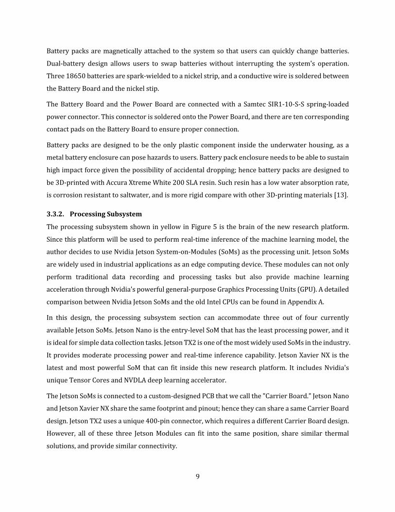
3.3.1. PowerSubsystemTheinternalspaceofthemainhousingcanbefurtherdividedintofoursections,asshowninFigure
5.Thepowersubsystem,asshowninred,consistsoftwobatterypacksandaprintedcircuitboard
(PCB)thatregulatesthepowerconversionanddistributionforthesystem.Insideeachbatterypack,
therearethree18650industrialstandardlithium-ionrechargeablebatteriesandanotherPCBthat
monitorsthebatterystatus.WecommonlyrefertothePCBinsidethebatterypackasthe"Battery
Board"andreferthepowerregulationPCBinsidethehousingasthe"PowerBoard."
Figure4.Mainhousingexteriorshellviewingfrombackside.Theredsectionsaredesignedtoimprovetheoverallrigidityofthedevice.
Figure5. Internalarrangementinsidemainhousing.Leftandrightpictureshowsthesystemfromtwoperspectis.Redsectionrepresentsthepowersubsystem;yellowsectionrepresentstheprocessingsubsystem;greensectionrepresentstheimagingsubsystem;bluesectionrepresentstheuserinterface.
9
Batterypacksaremagneticallyattachedtothesystemsothatuserscanquicklychangebatteries.
Dual-battery design allows users to swap batterieswithout interrupting the system's operation.
Three18650batteriesarespark-wieldedtoanickelstrip,andaconductivewireissolderedbetween
theBatteryBoardandthenickelstip.
TheBatteryBoardand thePowerBoardare connectedwithaSamtecSIR1-10-S-S spring-loaded
powerconnector.ThisconnectorissolderedontothePowerBoard,andtherearetencorresponding
contactpadsontheBatteryBoardtoensureproperconnection.
Batterypacksaredesignedtobe theonlyplasticcomponent inside theunderwaterhousing,asa
metalbatteryenclosurecanposehazardstousers.Batterypackenclosureneedstobeabletosustain
highimpactforcegiventhepossibilityofaccidentaldropping;hencebatterypacksaredesignedto
be3D-printedwithAccuraXtremeWhite200SLAresin.Suchresinhasalowwaterabsorptionrate,
iscorrosionresistanttosaltwater,andismorerigidcomparewithother3D-printingmaterials[13].
3.3.2. ProcessingSubsystemTheprocessingsubsystemshowninyellowinFigure5 isthebrainofthenewresearchplatform.
Sincethisplatformwillbeusedtoperformreal-timeinferenceofthemachinelearningmodel,the
authordecidestouseNvidiaJetsonSystem-on-Modules(SoMs)astheprocessingunit.JetsonSoMs
arewidelyusedinindustrialapplicationsasanedgecomputingdevice.Thesemodulescannotonly
perform traditional data recording and processing tasks but also provide machine learning
accelerationthroughNvidia'spowerfulgeneral-purposeGraphicsProcessingUnits(GPU).Adetailed
comparisonbetweenNvidiaJetsonSoMsandtheoldIntelCPUscanbefoundinAppendixA.
In this design, the processing subsystem section can accommodate three out of four currently
availableJetsonSoMs.JetsonNanoistheentry-levelSoMthathastheleastprocessingpower,andit
isidealforsimpledatacollectiontasks.JetsonTX2isoneofthemostwidelyusedSoMsintheindustry.
Itprovidesmoderateprocessingpowerandreal-timeinferencecapability.JetsonXavierNXisthe
latest andmostpowerful SoM that can fit inside thisnew researchplatform. It includesNvidia's
uniqueTensorCoresandNVDLAdeeplearningaccelerator.
TheJetsonSoMsisconnectedtoacustom-designedPCBthatwecallthe"CarrierBoard."JetsonNano
andJetsonXavierNXsharethesamefootprintandpinout;hencetheycanshareasameCarrierBoard
design.JetsonTX2usesaunique400-pinconnector,whichrequiresadifferentCarrierBoarddesign.
However, all of these three JetsonModules can fit into the same position, share similar thermal
solutions,andprovidesimilarconnectivity.

10
In order to protect the Carrier Board from bending and twisting during the assembly and
maintenanceprocesses,theauthordesignsacustomaluminumframethatattachestotheCarrier
Board.ThismetalframesignificantlyincreasestherigidityoftheCarrierBoardandprotectsitfrom
accidentaldamage.
ThelifecycleofJetsonSoMswillalsoimpactthelifecycleofournewplatform.AccordingtoNvidia's
website,bothJetsonNanoandJetsonTX2willbeavailabletopurchaseuntil2025,whileJetsonXavier
NXwillremainavailableuntil2026[14].
3.3.3. ImagingSubsystemTheimagingsubsystemisshowningreeninFigure5.Whenoursystemcapturesimagesunderwater,
thelightmustfirstgothroughawaterproofdomeportorflatport,thengothroughalens,andfinally
hit our image sensor. This section will introduce the design considerations and possible
configurationsofthesethreecomponentsintheimagingsubsystem.
UnderwaterPorts
When the light first enters the underwater system, it will first go through an underwater port.
Underwater ports are usually made with acrylic or glass front pieces. For general underwater
photography,acrylicfrontpiecesaremorewidelyusedastheyarecheaperandmorelightweight.
However,forourunderwaterpolarizationimaging,acrylicportswillcreatepolarizationeffectswhen
theyareunderhighpressure [9].Hence, such researchplatformscanonlyusehigh-qualityBK-7
opticalglasswithanti-reflectioncoatinginoursystem.
However,thesestringentrequirementsalsomeanthatitishardtocustomordersuchglasspieces
andintegrateintooursystem.Luckilytherearequiteafewmanufacturesproduceunderwaterports
withtheseglasses,anddesignersonlyneedtofollowtheirmechanicalspecificationtomounttheir
portsontoourresearchplatform.Oneof themostwidelyusedunderwaterportstandards is the
Nauticamportsystem.Theydefinefourdifferentportdiameters:N85,N100,N120,andN200.The
letter "N" stands forNauticam and the number specifies the diameter inmillimeters at the port
bayonet.
Inthecurrentdesign,thesystemutilizestheN120ports.Adomeportisattachedtothemainhousing
withacustom-designedportadapter.Bychangingtheportadapter,thesystemcanaccommodate
differentport standards.To ensure theprecise optical center alignment, the authordesigns four
alignmentpinsontheportadapterandfouralignmentholesonthefrontplateofthemainhousing.
Duringthefabrication,techniciansaretoldtoensureasnugfitbetweentheportadapterandthe
frontplate.

11
Lenses
Therearemanylenschoicesonthemarket,andtheycomewithdifferentsizes,bayonets,andoptical
characteristics.Itishardtodesignanenclosurethatcanfitalllenses.However,asthenewdesign
utilizestheNauticamportsystem,theresearchplatformwillbeabletophysicallyaccommodateany
lenssupportedbyNauticam.
Whenabaresensordirectlymountstotheunderwaterhousingfrontplate,acustom-designedlens
bayonet can bemounted to the port adapter to ensure the precise optical center alignment and
accurate focaldistance.The lenscanthenbemountedto the lensbayonet toensure idealoptical
performance.Currently,theauthorwasabletosuccessfullyimplementtheCanonEFmount,Cand
CSmount,andPLmountlensbayonetadapter.
Whenacompletecameramoduleismountedinsidethemainhousing,userscansimplypurchasea
lensbayonetconvertertoproperlymountthelens.
Imagers
Whenanimagingdeviceisdesignedfromscratch,theimagesensoranditscarrierPCBcanbedirectly
mountedtothefrontplateofthemainhousing.Thefrontplatewillbeabletofitanimagesensor
withupto70mmdiagonalsize.Similartotheportadapterdesign,severalprecisionalignmentpins
werereservedtoensuretheoptimalopticalcenteralignment.
Whenanoff-the-shelfcameramoduleisdesired,userscanmountthemoduletoacustom-designed
slider,asshowninFigure6.Theslidersitsontopofa"V"shapedbasetoensureprecisealignment,
andthesliderpositioncanbeeasilyadjustedwithalongadjustmentscrew.Twolinearballbearing
Figure6.Imagingsubsystemassembly.AFLIRBlackFlySMachineVisonCameraandFujinonFE185C057HA-1isshown.Thecameraisattachedtoaslidersystemwhosepositioncanbeadjustedwiththelonggreyscrewattheback.

12
assembliesonthebasecanensurethesmoothoperationoftheslider.Thebaseisthenattachedtoan
"L"shapedbracket,andthebracketisattachedtothefrontplate.Again,multiplealignmentholesand
alignment pinsweredesignedbetween theseparts to ensure theoptical center of the camera is
preciselyalignedtotheexternaldomeport.
3.3.4. UserInterfaceTheuser-accessibleinputs/outputs(IO)areshowninblueinFigure5.Adetaileduser-accessibleIOs
diagram is shown in Figure 7. Since this underwater imaging platform is designed for research
purpose, users may frequently modify and debug the software on this platform. To facilitate
developmentneeds, theauthor includesmultiplecommonlyused IOs.Userscanaccess these IOs
whenthecoverisopened.ThesedebugIOsincludesahigh-definitionmultimediainterface(HDMI)
1.2connector,anRJ45connectorthatsupportsIEEE802.3ab1000Base-TGigabitEthernetstandard,
andauniversalserialbus(USB)3.2Gen1Type-Aconnector.TheHDMIconnectorallowsusersto
connect the system toanexternalmonitor for easydebugaccess.Theethernet connectorallows
userstoconnectJetsonmoduletoalocalareanetworkfordebuggingorconnecttotheinternetfor
systemandsoftwareupdates.TheUSBconnectorallowsuserstoplugkeyboardandmousetothe
system.
Inadditiontothedebugaccess,userIOsalsoincludeapush-buttonforsystempoweron,andaUSB
TypeCPowerDeliveryconnector forupto100-watt fastchargingforthebattery.Twogroupsof
light-emittingdiodes(LED)arealsoavailabletoindicatebatterystatus.
Intheoldunderwatersystem,datawerestoredinanon-removableM.2solid-statedrive,posinga
significantchallengewhenuserswanttotransferdataontheboat.Inthisnewdesign,theauthor
adoptsthenewCompactFlashAssociationCFexpress2.0TypeBremovablestoragestandard.This
newstandardutilizesNon-VolatileMemoryExpress(NVMe)specificationasthedatatransmission
protocol,allowuserstowritetoCFexpressremovablecardsatupto2GBpersecondspeed[15].
Currently,thisstoragesolutionwillallowuserstohaveamaximumof2TBofstoragespaceinside
thenewsystem,buttheCFexpresscardmanufacturesmayproducehighercapacityvariantsinthe
future.InadditiontotheCFexpresscard,userscanalsouseaSecureDigitalCard(SDCard)tostore
Figure7.Userinterfaceinsidethemainhousing.ThenameofeachIOislabeledonthepicture.
13
the system and software configuration files. This feature allows users to quickly swap between
multiplesoftwareversionsorconfigurationswhentheyareoutinthefield.
Alloftheconnectorsandsocketsmentionedabovearesolderedtothe"IOBoard."Thisdesigngives
users the flexibility of migrating to other emerging specifications or changing to a different IO
combinationinthefuture.
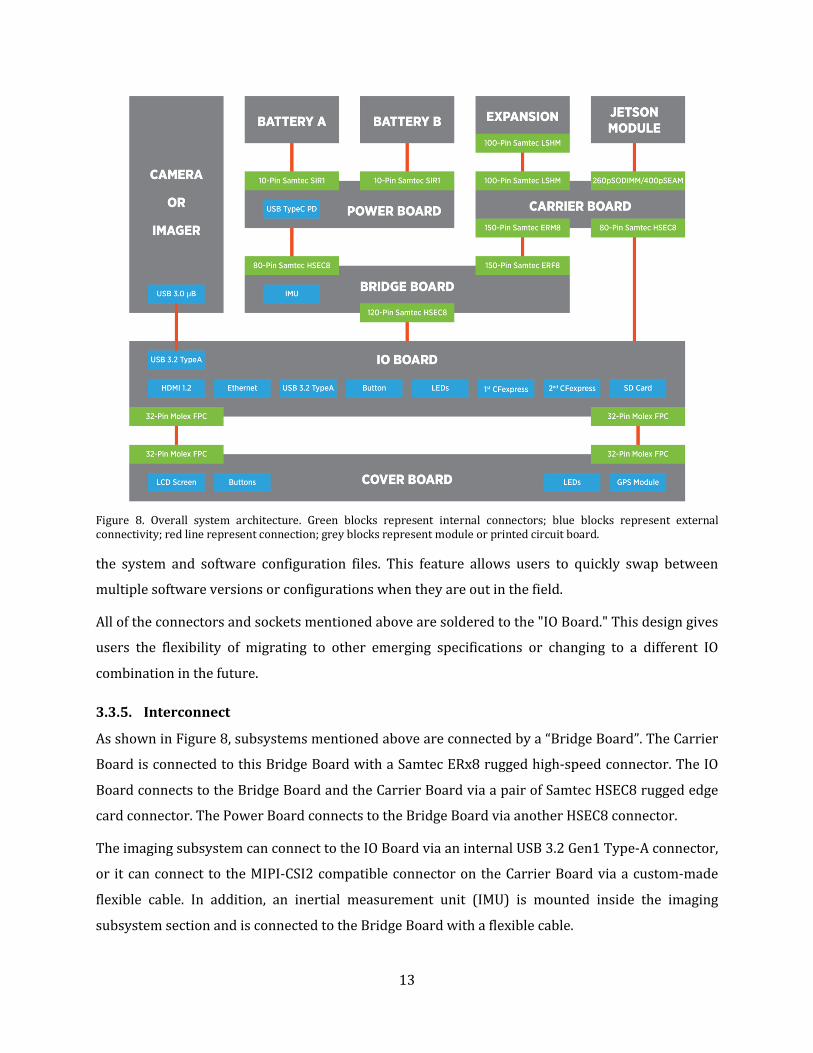
3.3.5. Interconnect
AsshowninFigure8,subsystemsmentionedaboveareconnectedbya“BridgeBoard”.TheCarrier
BoardisconnectedtothisBridgeBoardwithaSamtecERx8ruggedhigh-speedconnector.TheIO
BoardconnectstotheBridgeBoardandtheCarrierBoardviaapairofSamtecHSEC8ruggededge
cardconnector.ThePowerBoardconnectstotheBridgeBoardviaanotherHSEC8connector.
TheimagingsubsystemcanconnecttotheIOBoardviaaninternalUSB3.2Gen1Type-Aconnector,
or itcanconnect to theMIPI-CSI2compatibleconnectorontheCarrierBoardviaacustom-made
flexible cable. In addition, an inertial measurement unit (IMU) is mounted inside the imaging
subsystemsectionandisconnectedtotheBridgeBoardwithaflexiblecable.
Figure 8. Overall system architecture. Green blocks represent internal connectors; blue blocks represent externalconnectivity;redlinerepresentconnection;greyblocksrepresentmoduleorprintedcircuitboard.

14
3.4. ThermalDesignElectronicsneedtobekeptinanacceptabletemperaturerangetoensuretheiroptimaloperation.In
thenewunderwaterresearchplatform,fourmaincomponentswillgenerateasignificantamountof
heat.
ThefirstcomponentisJetsonModule.Inthenewdesign,theauthorstrictlyfollowstheJetsonDevice
ThermalDesignGuidelinepublishedbyNvidia, andefficientlydump theheat into theoutermost
housing.Thehousingcanthenbecooledbyseawater.AdetailedthermalstackupisshowninFigure
9.
CFexpressCards,powerregulatorsonthePowerBoard,andimagerorcameramodule insidethe
imagingsubsystemwillalsocreateasignificantamountofheat.Eachofthesecomponentsisattached
toametalplateandtheheatwillbeconductedtotheexteriorandtheheatwillbedumpedintothe
seawater.
3.5. ExpansionandUpgrade3.5.1. ExternalExpansionsThisnewunderwaterresearchplatformisdesignedwithfutureexpansionandupgradeinmind.At
thebottomsideofthemainunderwaterhousing,fiveexternalmountingpointsallowuserstodesign
custombottomplatestofitdifferentneeds.
Theweightof thesystemmaychangeafter futuremodifications.Hence,additionalweightcanbe
attachedtothecustombottomplatetoensurethesystemremainnegativelybuoyant.Oneortwo
handlescanalsobeattachedtoacustombottomplatetoensureeasydevicehandlingduringthedata
collectionprocessunderwater.Duringmost of ourdata collection trips so far, thedevicewill be
attached to a tripod underwater. A quick-release bottomplate can also be attached to a custom
designedbottomplatetohelpdiversexpeditethedevicesetupprocessunderwater.
Thismountingoptionalsoenablesthepossibilityofattachingthenewsystemtoaremotelyoperated
underwatervehicle(ROV)toexploreandrecorddataindangerousareas.
Figure9.Jetsonmodulethermalstackupinsidethesystem.Allyellowblocksrepresentthermalinterfacematerials.

15
3.5.2. UnderwaterConnectionsAlthough thenewsystemhasanembeddedmonitorandotherexternal connectionsareunlikely
under current research requirements, the author still reserved two 26 mm diameter external
connectionports.
ThesetwoportsarelargeenoughtofitaNauticamUnderwaterHDMIorSerialDigitalInterface(SDI)
connector,allowuserstohaveanadditionalmonitorunderwaterortransmitthevideotoaboat.
Thesetwoportscanalsoaccommodateunderwaterethernet,power,andcoaxialcablesdesignedby
SubConn[16].Afurtherdiscussionofpotentialusecasesiscoveredinsection4.2.
Users can also design expansion modules that directly attach to these two ports. An expansion
modulewithbuttoninputs,waterdepthsensor,andwatertemperaturesensorisproposedandwill
beimplementedbytheauthor.
3.5.3. InternalUpgradesItisalsopossibletoupgradetheinternalcomponentsofthesystem.Inthecurrentdesign,thepower
subsystem,theprocessingsubsystem,andtheuserinterfacemoduleareallattachedtoabaseplate.
Thisbaseplateisattachedtothefrontplateofthemainhousingviaonlyfivemountingscrews.Hence,
itwould be straightforward to upgrade and reuse the housing to fulfill other research needs by
redesignthebaseplate.

16
4. ElectricalDesignAfterfinalizingthemechanicaldesign,theauthorbreaksoutthesignalscomingfromNvidiaJetson
Moduleandassignsallthesignalstodifferentprintedcircuitboards(PCB).Section4.1providesan
overviewoftheelectricaldesign.Section4.2coversseveralexamplesofpossiblefutureusecases.
4.1. OverviewAsmentionedinprevioussections,thenewunderwaterresearchplatformconsistsofsevendifferent
PCBs.SuchamodulardesignallowsuserstomodifyoneormorePCBstosuittheirneedswithout
redesignthewholesystem.
Figure10showssomecommon interfaces Jetsonmodulesprovide. JetsonTX2willprovidemany
additionalinterfacesduetoitsdense400-pinconnector.JetsonNanoandJetsonXavierNXwillbe
limitedtotheinterfacesshowninthefigure[17].
Figure10.Jetsoninterfacesandcorrespondingendpointsinourdesign.Greyboxesrepresentprintedcircuitboards;greenboxesrepresentconnectionendpoints;yellowboxesrepresentactivecomponents;blueboxesrepresentdifferentsignalsfromJetson;redlinesdemonstratethesignalpath.

17
JetsonModulesdirectlyattachetotheCarrierBoard,makingtheCarrierBoardthemostcomplexPCB
inthesystem.JetsonModulesonlyprovideoneGigabitEthernet(GbE)interface,butthenewdesign
requiresoneGbEreservedontheExpansionBoardwhilehavinganotherGbEconnectoravailablefor
debuggingandsoftwareupdateaccess.ThenewdesignutilizesaGbEswitchtosplittheinterface
intotwotofulfillsystemneeds.Inaddition,aMIPICSI-2x4interfaceisreservedontheCarrierBoard,
allowusers touse theMIPI interface camera inside the system.An Inter IntegratedCircuit (I2C)
interfaceandaSerialPeripheralInterface(SPI)isalsoreservedontheCarrierBoardforpotential
upgrade.AReal-TimeClock(RTC)moduleisplacedonthecarrierboardtoprovidetheJetsonModule
accuratetimewhenthesystemisnotpoweredup.
MostofsignalsfromJetsonModulearepassedtotheBridgeBoard,IOBoard,andExpansionBoard.
TherearetwopossibleroutesforsignalstotravelfromtheCarrierBoardtotheIOBoard.Thefirst
setofsignalsgoesdirectlyfromtheCarrierBoardtotheIOBoard.Thissetofsignalsincludefour
PeripheralComponentInterconnectExpress(PCIe)channelsforCFexpressstoragecardsandaGbE
foruseraccess.Thesesignalsarehighspeeddifferential signalsandusuallyhaveahighersignal
integrityrequirement.DirectlyroutethesesignalsfromtheCarrierBoardtotheIOBoardcanensure
highersignalquality.ThesecondsetofsignalsgoesfromtheCarrierBoardtotheIOBoardviathe
BridgeBoard.Thissetofsignals includea fewlowspeedsignals likeSPIandI2C,anda fewlow-
priorityhighspeedsignals likeHDMIandUSB.Thisdesign isdue to the limitedspace inside the
housing, and the Carrier Board to the IO Board interface has a limited pin-count on the edge
connector.Havingasecondsignalpathisnotidealbutistheonlysolutionforthenewsystem.
ThePowerBoardisattachedtotheBridgeBoardinthesystem.AstheBridgeBoardisconnectedto
boththeCarrierBoardandtheIOBoard,powerfromthebatterycanbeeasilydivided.ThePower
Board features a microcontroller unit (MCU) that can talk with Jetson Module via Universal
AsynchronousReceiver-Transmitter(UART)interface.TheMCUonthePowerBoardactasapower
managementunitthatswitchesthepowersourcebetweenbatteryA,batteryB,andexternalpower.
ItcanalsowakeupandshutdownJetsonModulewhennecessary.ThePowerBoardalsofeaturesa
USBTypeCPowerDeliverycapableconnector.Thisuser-accessibleinterfaceprovidesupto100W
ofpower,allowuserstochargetwobatterieswhenthesystemisrunning.
TheBatteryBoardisinsideallbatterypacks.ThereisanIContheBatteryBoardthatcontrolsthe
charginganddischargingprocessofthebattery.Thischipwillalsomonitorthebatteryhealthstatus,
thebatterytemperature,andthebatteryusecycles.ItwillalertthepowermanagementMCUand
JetsonModulewhenthebatteryabnormallyoccurs.Thisdesignguaranteesthebatterysafetyand
canpreventmost,ifnotall,battery-relatedsafetyhazardinthesystem.

18
TheCoverBoardmainlyservestheMIPIDSIscreenandtheGPSmodule.TheMIPIscreencanhelp
usersunderstandthesystemoperatingstatuswhenuser isunderwater,andtheGPSmodulecan
provideaccuratetimeandlocationwhenuser isabovewater.However, JetsonXavierNXmodule
doesnotprovideaMIPIDSIsignal,hencethesystemneedstoconvertHDMIsignaltoMIPIsignal.As
userswillnotusetheembeddeddisplaywhentheHDMIisaccessible,aHDMIswitchisplacedonthe
IOBoard. JetsonModule can switch between twopossibleHDMIdownstreamport by toggling a
General-Purpose InputOutput (GPIO) pin. One of the downstreamHDMI port connects toHDMI
connector, allowusers to connect the system toanexternalmonitor fordebugaccess.Theother
downstreamHDMIportconnectstoaHDMItoMIPIDSIconverter.Convertedsignalthengoestothe
embeddedscreen.
Lastly, the Expansion Board features a lot of reserved interfaces. Next section introduces a few
possibleusecasesinvolvetheExpansionBoard.
4.2. ExpansionUseCases
4.2.1. CameraandImagerConfiguration
Figure 11 shows two possible imaging configurations in the system.When a camera module is
desired,thereservedUSBType-Aconnectorinsidetheimagingsubsystemcompartmentcanbeused
toconnectthecamera.Whenabareimagerisdesired,userscancreateathree-boardstacktohandle
thedatatransmission.Animagerboardcanbemountedtothefrontplateoftheunderwaterhousing,
asdescribedinsection3.3.3.ThenaFieldProgrammableGateArray(FPGA)boardcanbeattached
totheImagerBoard.FPGAcanbeusedtoperformimagerreadoutsequence,imageprocessing,and
MIPItransmission.ThentheMIPIsignalcanbetransmittedtotheCarrierBoardviatheTransmitter
Board.ThisdesignallowsustoreusetheFPGABoardandImagerBoardinotherconfigurationor
application, such as the underwater panoramic application mentioned in section 4.2.5. The
TransmitterBoardandtheCarrierBoardcanbeconnectedwithaI-PEXmicrocoaxialcable[18].
Suchcablesareflexibleandaredesignedfordifferentialsignals,providesusersreliableMIPIsignal
transmission.
Figure11.Possiblecameraandimagerconfigurationsinthesystem.Figureontheleftshowsaconfigurationforimagingsensors;rightfigureshowsaconfigurationforcamera.

19
4.2.2. ExternalModule
Figure12showsapossibleexternalmoduleusecase.Astheunderwaterhousingdoesnotintegrate
anybuttoninput,usersmayhavedifficultyadjustsettingsunderwater.Thismoduleattachestoone
ofthetwounderwaterexpansionportsonthemainhousing.Theexternalexpansionmodulecontains
anMCUthatcancontrolthebuttons,LEDs,andsensorsontheexternalmodule.Theexternalmodule
canconnect to theExpansionBoardandtalkwith JetsonModule throughUART.However,as the
externalmodulehasbuttons,ithasahigherpossibilityofwaterleaking.Incaseofleaking,epoxy-
filledconnectioncanpreventanydamagetothemainhousing.
4.2.3. ExternalMonitorAlthoughtheembedded5-inchmonitorissufficientformostusecases,theremightbescenariosthat
asecondexternalunderwatermonitorisrequired.Figure13showstwopossibleexternalmonitor
configurations.The figureon the topshowsa configuration forHDMImonitors.Nauticamhasan
underwaterHDMIconnectorthatutilizetheMicroHDMIconnector.AstheExpansionBoardhasa
reservedHDMIinterface,theNauticamadaptercanbedirectlyconnectedtotheExpansionBoard.
TheotherendoftheNauticamcablegoesintotheunderwatermonitorhousingandcanbedirectly
pluggedintothemonitor.ThefigureonthebottomshowsaconfigurationforSDImonitors.HDMI
signal can converts to SDI signalwith a small Lattice FPGA. As the SDI utilize a coaxial cable to
Figure12.Exampleexternalmoduleconfiguration.
Figure 13. Two possible external monitor configurations. Figure on the top shows a possible connection with HDMImonitors.FigureonthebottomshowsapossibleconnectionwithSDImonitors.

20
transmitthedata,anadditionaldrivercircuitryisrequired.TheSDIsignalcanthengothroughthe
NauticamSDIconnector,andfeedintotheSDImonitor.
4.2.4. ContinuousRecording
Currently the new system is capable of performing continuous recording for around four hours.
However,usersmayneedtorecordthepolarizationimagescontinuouslyfordaysorweeksinthe
future. It is impossible todesignabatterypack that last severaldaysor fit adisk that can store
hundredsofterabytesofdatainsidethehousing.Thenewdesignneedstobeabletocontinuously
transmitdata toaPCabovewaterwhileprovidingpowerto thesystemfromthegroundstation.
QualcommQCA7500isachipsetthatcanperformPowerLineCommunication(PLC)[19].Itallows
us to achieve a 1000Mbps data transmission while providing power for the system through a
neutrally buoyant power cable. The PC attached to the ground stationwill be able to see Jetson
Moduleinsidetheunderwatersystemasanormalethernetdevice,andJetsonModulecantransmit
datatothePCasiftheyareinalocalareanetwork.
AsshowninFigure14,oneofthetwobatteriesinsidetheunderwatersystemcanbereplacedwith
thePLCmodule.Thismodifiedbatterywillkeeptheoriginalcontactpadssothatitcanprovidepower
to the system without modifying the power path. The ethernet signal can be connected to the
reservedGigabitEthernetinterfaceontheExpansionBoardviaaFlatPrintedCircuit(FPC)cable.
4.2.5. UnderwaterPanoramicAsmentionedinsection2.2,researchersareexploringthepossibilityofusingmultiplepolarization
cameras to create a panoramic polarization image underwater. However, having three imaging
devicefitinonehousingwillnotonlyaffecttheimagequalitybutalsoposeriskstothewholesystem
duetotheadditionalcomplexity.Inthenewsystemdesign,itispossibletousethecurrenthousing
Figure14.AnexamplediagramofusingPowerLineCommunicationtoenablelong-termcontinuousrecording.Theblackboxesandtracesrepresentthepowerpath.

21
asadatarecordingandprocessingcenterunderwaterandconnecttothreeormoreexternalcameras
toperformpanoramicrecording.
Figure15showsapossibleexpansionofthesystemthatallowsresearcherstoconnectthreeexternal
cameramodulestorecordunderwaterpanoramicimages.
On the left side of the diagram, inside themain housing, JetsonModules can record three video
streamsviatheMIPIinterface.However,eachMIPIinterfacehasatleasta16-pindifferentialsignal
connection, making connecting the MIPI signals to the outside of the main housing impractical.
Gigabit Multimedia Serial Link (GMSL) is designed to solve this issue [20]. GMSL was initially
designedtobeusedinautomobiles,andasinglecablesolutionwillmaketheautomobileassembly
processaloteasier.MIPIsignalscanbeconvertedtoaGMSLsignalviaaGMSLserializer,andaGMSL
signalcanbedeserializedtoMIPIsignalsaswell.TheGMSLsignalcanbetransmittedviaacoaxial
cable.SubConnoffersanunderwaterCoaxialCablewithSideContacts,whichcanallowustoreceive
GMSLsignalfromtheexternalcameraswhileprovidingpowertothem[16].
Inside the external camerahousing is a three-board stack.The ImagerBoard andFPGAboard is
alreadyintroducedinsection4.2.1andisreusedhere.TheTransmitterBoardreceivesthepower
fromthemainhousingwhileconvertingMIPIsignalstotheGMSLsignal.Thisdesignallowsusto
reusemostoftheimagingsystemdesignandminimizetheextraengineeringcost.
WhentheGMSLsignalarrivesinthemainhousing,theExpansionBoardcandeserializetheGMSL
signaltoMIPIsignals.However,asshownearlier inFigure10,theExpansionBoardonlyhastwo
Figure15.Anexamplediagramofconnectingthreeexternalcameramodulestoperformunderwaterpanoramicimaging.

22
MIPI interface,while theCarrierBoardhasanadditionalone.Thisconfigurationwas intendedto
benefituserswhenonlyoneMIPIinterfaceisrequired,astheydonotneedtodesignanewExpansion
Boardtofulfilltheirneed.WhenthreeMIPIinterfacesontheExpansionBoardaredesired,theuser
canuseasmall I-PEX jumpercable toconnect theCarrierBoardMIPI interface to theExpansion
Board.

23
5. ConclusionandFutureWorkThe author successfully designed a compact, waterproof, and high-performance underwater
researchplatformthat iscapableofperformingunderwatergeolocalizationtasks.Thedesignhas
been prototypedwith 3D printed technology and proved thewater-tightness of the system. The
design isuser friendlyandeasy tooperateandhasmuchpotential for futureupgrades.The final
designweighsonly3kgandmeasuresonly105by105by170mmforthemainunderwaterhousing.
The author workedwith his colleague and finalized the power subsystem design and tested its
functionality. The power subsystem can charge and discharge the battery pack, and the power
managementMCUcancontrolthepowersubsystemtoswitchbetweenmultiplepowersources.The
powersubsystemcanacceptupto100WofpowerfromtheUSBTypeCPowerDeliveryport.
However,thisisanambitiousprojectwithmanyskillsandeffortsinvolved.Therearemanyongoing
workstoimprovethedesignfurther.Theauthoriscurrentlyworkingonaprototypeoftheexternal
modules that can take button input underwater. The author is also evaluating the design for
compatibility with various imaging systems. Also, the author is looking to further optimize the
mechanicaldesignwithfiniteelementanalysistools.
Theauthorisalsoworkingcloselywithhiscolleaguestoimplement,prototype,andtesttheelectrical
design.FirmwareandsoftwareonthePowerManagementMCUandtheJetsonModulearealsounder
development,andtheauthorisperformingvarioustestsandbenchmarksonthesystem.

24
References[1] A. I. Al-Shamma'a, A. Shaw and S. Saman, "Propagation of electromagnetic waves at MHz
frequenciesthroughseawater,"inIEEETransactionsonAntennasandPropagation,vol.52,no.11,pp.
2843-2849,Nov.2004.
[2]L.Whitcomb,D.Yoerger andH. Singh, "Advances inDoppler-basednavigationofunderwater
roboticvehicles,"inProceedings1999IEEEInternationalConferenceonRoboticsandAutomation(Cat.
No.99CH36288C),vol.1,pp.399-406,1999.
[3]D.Goshen-Meskinand I.Y.Bar-Itzhack, "Unifiedapproach to inertialnavigation systemerror
modeling,"inJournalofGuidance,Control,andDynamics,vol.15,no.3,pp.648653,1992.
[4]L.Paull,S.Saeedi,M.Seto,andH.Li,"AUVNavigationandLocalization:AReview,"inIEEEJournal
ofOceanicEngineering,vol.39,no.1,pp.131-149,2014.
[5]Kuc,Roman."EcholocationwithBatBuzzEmissions:ModelandBiomimeticSonarforElevation
Estimation,"InJournaloftheAcousticalSocietyofAmerica,vol.131,no.1,p.561,Jan.2012.
[6]H.H.Thoen,M.J.How,T.-H.Chiou,andJ.Marshall,"ADifferentFormofColorVisioninMantis
Shrimp,"inScience,vol.343,no.6169,pp.411–413,2014.
[7]D. C. Parkyn, J. D. Austin, andC.W.Hawryshyn, "Acquisition of polarized-light orientation in
salmonidsunderlaboratoryconditions,"inAnimalBehaviour,vol.65,no.5,pp.893–904,2003.
[8]S.B.Powell,R.Garnett,J.Marshall,C.Rizk,andV.Gruev,"Bioinspiredpolarizationvisionenables
underwatergeolocalization,"inScienceAdvances,vol.4,no.4,2018.
[9] S. B. Powell, "Underwater Celestial Navigation Using the Polarization of Light Fields," in
EngineeringandAppliedScienceTheses&Dissertations,no.245,2017.
[10]Marshall,Justin."Bio-inspiredGPS-freeNavigationUsingMantisShrimp(Stomatopod)Vision,"
inDefenseTechnicalInformationCenter,2019.
[11]T.H.Waterman,"Polarizationofscatteredsunlightindeepwater,"inDeepSeaResearch,vol.3,
pp.426-434,1955.
[12] O-Ring Design and Technical Quick Reference Information, webpage, accessed April 2020.
Availableat:https://www.marcorubber.com/o-ring-design-technical-index.htm
[13]MaterialsSelectionGuideforStereolithography,datasheet,3DSystems,Inc.,2020.Availableat:
https://www.3dsystems.com/sites/default/files/2019-12/3d-systems-sla-material-selection-
guide-usen-2019-11-07-web.pdf

25
[14]JetsonProductLifecycle,webpage,accessedApril2020.Availableat:
https://developer.nvidia.com/embedded/community/lifecycle
[15] The CompactFlash Association Announces CFexpress 2.0 Specification, press release,
CompactFlashAssociation,2019.Availableat:
https://cofa.memberclicks.net/assets/docs/cfapress/cfexpress_2_0_press_release_20190228.pdf
[16]SubConnUnderwaterConnectors,webpage,accessedApril2020.Availableat:
https://www.macartney.com/what-we-offer/systems-and-products/connectors/subconn/
[17]HardwareForEverySituation–NvidiaJetsonModules,webpage,accessedApril2020.Available
at:https://developer.nvidia.com/embedded/develop/hardware
[18]I-PEXMicroCoaxialCableProductPage,webpage,accessedApril2020.Availableat:
https://www.i-pex.com/products#micro-coax-discrete-wire
[19] QCA7500 - Gigabit-Class Speeds Everywhere, product brief, Qualcomm Atheros, Inc., 2020.
Availableat:
https://www.codico.com/fxdata/codico/prod/media/Datenblaetter/AKT/QCA7500%20Product%
20Brief.pdf
[20]GigabitMultimediaSerialLink(GMSL)SerDesICs,webpage,accessedApril2020.Availableat:
https://www.maximintegrated.com/en/products/interface/high-speed-signaling/gmsl-
serdes.html

26
AppendixA.ProcessingSystemComparisonsTable1.ComparisonbetweenNvidiaJetsonNano,JetsonTX2,JetsonXavierNX,andIntelCorei76700TE.
NVIDIAJETSONNANO
NVIDIAJETSONTX2
NVIDIAJETSONXAVIERNX
INTELCOREI76700TE
CPUQuad-CoreARM
A57
Dual-CoreNVIDIADenverandQuad-CoreARMA57
6-coreNVIDIACarmel64-bit
CPU
~60%ofi7-6700K
GPU 128-coreNVIDIAMaxwell
256-coreNVIDIAPascal
384-coreNVIDIAVoltawith48TensorCores
IntelHDGraphics530
ACCELERATOR
- -
2xNVDLAEngine
7-WayVLIWVisionProcessor
-
MEMORY 4GBLPDDR4 8GBLPDDR4 8GBLPDDR4x 64GBDDR4PERFORMANCE(TFLOPS,FL16) 0.472 1.33 1.69 0.265[1]
POWER(W) 10 15 15 35
DIMENSION(MM) 69.6x45 87x50 69.6x45 120x120[2][1]Approximatedbaseon6700TEand6700Kperformancematrix.[2]Minimumsystemsize.