
Underwater binocular imaging of aerial objects versus the ...
8
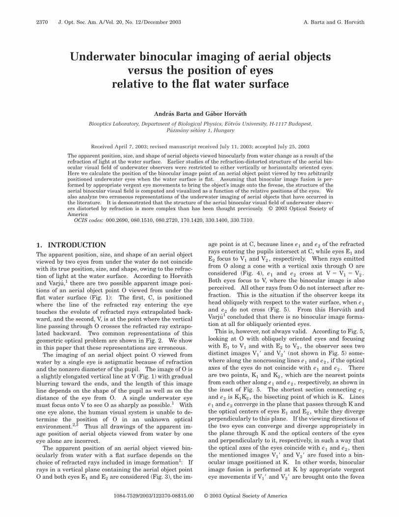
Underwater binocular imaging of aerial objects versus the position of eyes relative to the flat water surface Andra ´s Barta and Ga ´ bor Horva ´th Biooptics Laboratory, Department of Biological Physics, Eo ¨ tvo ¨s University, H-1117 Budapest, Pa ´ zma ´ ny se ´ta ´ ny 1, Hungary Received April 7, 2003; revised manuscript received July 11, 2003; accepted July 25, 2003 The apparent position, size, and shape of aerial objects viewed binocularly from water change as a result of the refraction of light at the water surface. Earlier studies of the refraction-distorted structure of the aerial bin- ocular visual field of underwater observers were restricted to either vertically or horizontally oriented eyes. Here we calculate the position of the binocular image point of an aerial object point viewed by two arbitrarily positioned underwater eyes when the water surface is flat. Assuming that binocular image fusion is per- formed by appropriate vergent eye movements to bring the object’s image onto the foveae, the structure of the aerial binocular visual field is computed and visualized as a function of the relative positions of the eyes. We also analyze two erroneous representations of the underwater imaging of aerial objects that have occurred in the literature. It is demonstrated that the structure of the aerial binocular visual field of underwater observ- ers distorted by refraction is more complex than has been thought previously. © 2003 Optical Society of America OCIS codes: 000.2690, 080.1510, 080.2720, 170.1420, 330.1400, 330.7310. 1. INTRODUCTION The apparent position, size, and shape of an aerial object viewed by two eyes from under the water do not coincide with its true position, size, and shape, owing to the refrac- tion of light at the water surface. According to Horva ´th and Varju ´, 1 there are two possible apparent image posi- tions of an aerial object point O viewed from under the flat water surface (Fig. 1): The first, C, is positioned where the line of the refracted ray entering the eye touches the evolute of refracted rays extrapolated back- ward, and the second, V, is at the point where the vertical line passing through O crosses the refracted ray extrapo- lated backward. Two common representations of this geometric optical problem are shown in Fig. 2. We show in this paper that these representations are erroneous. The imaging of an aerial object point O viewed from water by a single eye is astigmatic because of refraction and the nonzero diameter of the pupil. The image of O is a slightly elongated vertical line at V (Fig. 1) with gradual blurring toward the ends, and the length of this image line depends on the shape of the pupil as well as on the distance of the eye from O. A single underwater eye must focus onto V to see O as sharply as possible. 1 With one eye alone, the human visual system is unable to de- termine the position of O in an unknown optical environment. 2,3 Thus all drawings of the apparent im- age position of aerial objects viewed from water by one eye alone are incorrect. The apparent position of an aerial object viewed bin- ocularly from water with a flat surface depends on the choice of refracted rays included in image formation 1 : If rays in a vertical plane containing the aerial object point O and both eyes E 1 and E 2 are considered (Fig. 3), the im- age point is at C, because lines e 1 and e 2 of the refracted rays entering the pupils intersect at C, while eyes E 1 and E 2 focus to V 1 and V 2 , respectively. When rays emitted from O along a cone with a vertical axis through O are considered (Fig. 4), e 1 and e 2 cross at V 5 V 1 5 V 2 . Both eyes focus to V, where the binocular image is also perceived. All other rays from O do not intersect after re- fraction. This is the situation if the observer keeps its head obliquely with respect to the water surface, when e 1 and e 2 do not cross (Fig. 5). From this Horva ´th and Varju ´ 1 concluded that there is no binocular image forma- tion at all for obliquely oriented eyes. This is, however, not always valid. According to Fig. 5, looking at O with obliquely oriented eyes and focusing with E 1 to V 1 and with E 2 to V 2 , the observer sees two distinct images V 1 8 and V 2 8 (not shown in Fig. 5) some- where along the noncrossing lines e 1 and e 2 , if the optical axes of the eyes do not coincide with e 1 and e 2 . There are two points, K 1 and K 2 , which are the nearest points from each other along e 1 and e 2 , respectively, as shown in the inset of Fig. 5. The shortest section connecting e 1 and e 2 is K 1 K 2 , the bisecting point of which is K. Lines e 1 and e 2 converge in the plane that passes through K and the optical centers of eyes E 1 and E 2 , while they diverge perpendicularly to this plane. If the viewing directions of the two eyes can converge and diverge appropriately in the plane through K and the optical centers of the eyes and perpendicularly to it, respectively, in such a way that the optical axes of the eyes coincide with e 1 and e 2 , then the mentioned images V 1 8 and V 2 8 are fused into a bin- ocular image positioned at K. In other words, binocular image fusion is performed at K by appropriate vergent eye movements if V 1 8 and V 2 8 are brought onto the fovea 2370 J. Opt. Soc. Am. A/ Vol. 20, No. 12/ December 2003 A. Barta and G. Horva ´th 1084-7529/2003/122370-08$15.00 © 2003 Optical Society of America
Transcript of Underwater binocular imaging of aerial objects versus the ...
2370 J. Opt. Soc. Am. A/Vol. 20, No. 12 /December 2003 A. Barta and G. Horvath
Underwater binocular imaging of aerial objectsversus the position of eyes
relative to the flat water surface
Andras Barta and Gabor Horvath
Biooptics Laboratory, Department of Biological Physics, Eotvos University, H-1117 Budapest,Pazmany setany 1, Hungary
Received April 7, 2003; revised manuscript received July 11, 2003; accepted July 25, 2003
The apparent position, size, and shape of aerial objects viewed binocularly from water change as a result of therefraction of light at the water surface. Earlier studies of the refraction-distorted structure of the aerial bin-ocular visual field of underwater observers were restricted to either vertically or horizontally oriented eyes.Here we calculate the position of the binocular image point of an aerial object point viewed by two arbitrarilypositioned underwater eyes when the water surface is flat. Assuming that binocular image fusion is per-formed by appropriate vergent eye movements to bring the object’s image onto the foveae, the structure of theaerial binocular visual field is computed and visualized as a function of the relative positions of the eyes. Wealso analyze two erroneous representations of the underwater imaging of aerial objects that have occurred inthe literature. It is demonstrated that the structure of the aerial binocular visual field of underwater observ-ers distorted by refraction is more complex than has been thought previously. © 2003 Optical Society ofAmerica
OCIS codes: 000.2690, 080.1510, 080.2720, 170.1420, 330.1400, 330.7310.
1. INTRODUCTIONThe apparent position, size, and shape of an aerial objectviewed by two eyes from under the water do not coincidewith its true position, size, and shape, owing to the refrac-tion of light at the water surface. According to Horvathand Varju,1 there are two possible apparent image posi-tions of an aerial object point O viewed from under theflat water surface (Fig. 1): The first, C, is positionedwhere the line of the refracted ray entering the eyetouches the evolute of refracted rays extrapolated back-ward, and the second, V, is at the point where the verticalline passing through O crosses the refracted ray extrapo-lated backward. Two common representations of thisgeometric optical problem are shown in Fig. 2. We showin this paper that these representations are erroneous.
The imaging of an aerial object point O viewed fromwater by a single eye is astigmatic because of refractionand the nonzero diameter of the pupil. The image of O isa slightly elongated vertical line at V (Fig. 1) with gradualblurring toward the ends, and the length of this imageline depends on the shape of the pupil as well as on thedistance of the eye from O. A single underwater eyemust focus onto V to see O as sharply as possible.1 Withone eye alone, the human visual system is unable to de-termine the position of O in an unknown opticalenvironment.2,3 Thus all drawings of the apparent im-age position of aerial objects viewed from water by oneeye alone are incorrect.
The apparent position of an aerial object viewed bin-ocularly from water with a flat surface depends on thechoice of refracted rays included in image formation1: Ifrays in a vertical plane containing the aerial object pointO and both eyes E1 and E2 are considered (Fig. 3), the im-
1084-7529/2003/122370-08$15.00 ©
age point is at C, because lines e1 and e2 of the refractedrays entering the pupils intersect at C, while eyes E1 andE2 focus to V1 and V2 , respectively. When rays emittedfrom O along a cone with a vertical axis through O areconsidered (Fig. 4), e1 and e2 cross at V 5 V1 5 V2 .Both eyes focus to V, where the binocular image is alsoperceived. All other rays from O do not intersect after re-fraction. This is the situation if the observer keeps itshead obliquely with respect to the water surface, when e1and e2 do not cross (Fig. 5). From this Horvath andVarju1 concluded that there is no binocular image forma-tion at all for obliquely oriented eyes.
This is, however, not always valid. According to Fig. 5,looking at O with obliquely oriented eyes and focusingwith E1 to V1 and with E2 to V2 , the observer sees twodistinct images V18 and V28 (not shown in Fig. 5) some-where along the noncrossing lines e1 and e2 , if the opticalaxes of the eyes do not coincide with e1 and e2 . Thereare two points, K1 and K2 , which are the nearest pointsfrom each other along e1 and e2 , respectively, as shown inthe inset of Fig. 5. The shortest section connecting e1and e2 is K1K2 , the bisecting point of which is K. Linese1 and e2 converge in the plane that passes through K andthe optical centers of eyes E1 and E2 , while they divergeperpendicularly to this plane. If the viewing directions ofthe two eyes can converge and diverge appropriately inthe plane through K and the optical centers of the eyesand perpendicularly to it, respectively, in such a way thatthe optical axes of the eyes coincide with e1 and e2 , thenthe mentioned images V18 and V28 are fused into a bin-ocular image positioned at K. In other words, binocularimage fusion is performed at K by appropriate vergenteye movements if V18 and V28 are brought onto the fovea
2003 Optical Society of America
A. Barta and G. Horvath Vol. 20, No. 12 /December 2003 /J. Opt. Soc. Am. A 2371
of eye E1 and E2 , respectively. In humans, the opticalaxes passing through the foveae and the optical centers ofthe eyes can converge strongly in a plane through the op-tical centers but can diverge only slightly (a few degrees)perpendicularly to it.3 Thus if the minimum distanceK1K2 is too large, binocular fusion cannot be performed,and the observer sees two distinct images along e1 and e2at an indefinite distance. Hence the smaller K1K2 is, thegreater is the chance of the existence of the binocular im-age point K of the object point O. When eye E2 rotatesaround eye E1 in such a way that the baseline between
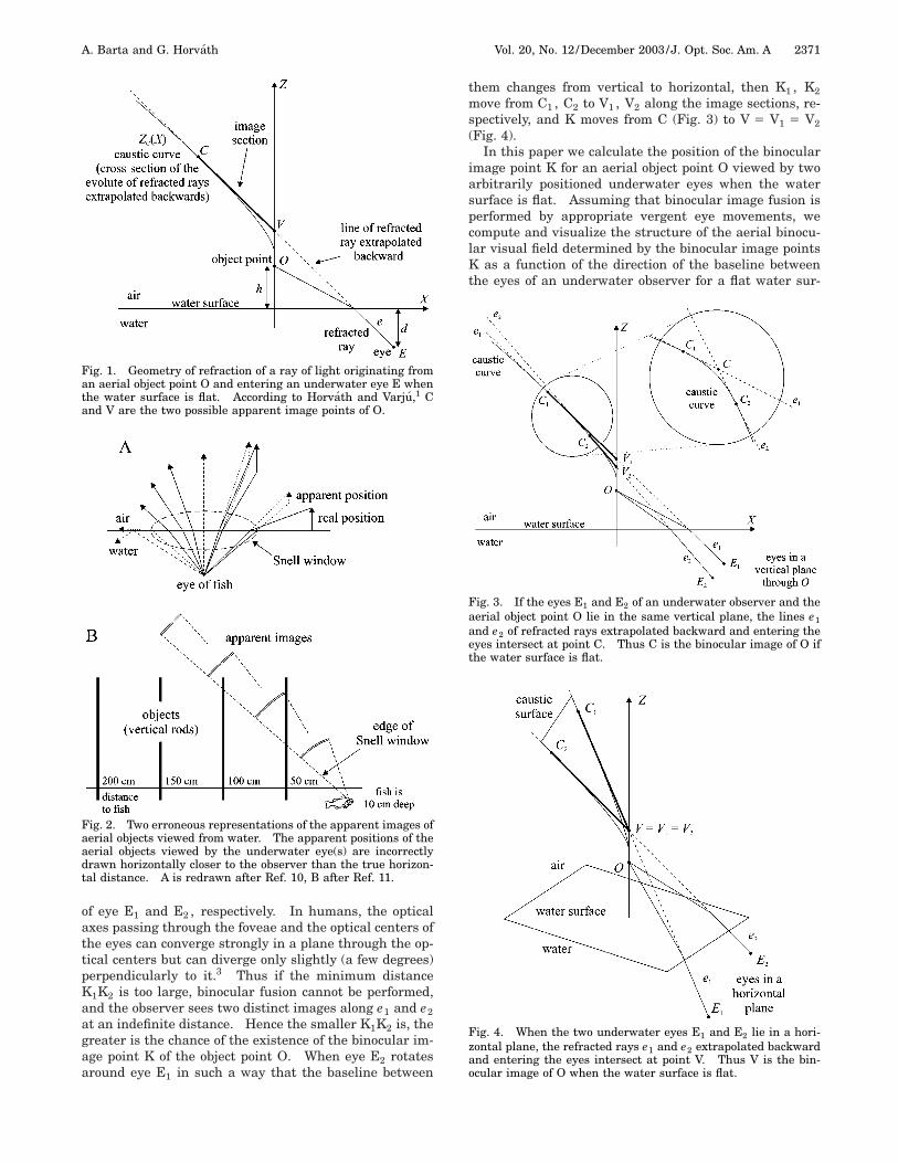
Fig. 1. Geometry of refraction of a ray of light originating froman aerial object point O and entering an underwater eye E whenthe water surface is flat. According to Horvath and Varju,1 Cand V are the two possible apparent image points of O.
Fig. 2. Two erroneous representations of the apparent images ofaerial objects viewed from water. The apparent positions of theaerial objects viewed by the underwater eye(s) are incorrectlydrawn horizontally closer to the observer than the true horizon-tal distance. A is redrawn after Ref. 10, B after Ref. 11.
them changes from vertical to horizontal, then K1 , K2move from C1 , C2 to V1 , V2 along the image sections, re-spectively, and K moves from C (Fig. 3) to V 5 V1 5 V2(Fig. 4).
In this paper we calculate the position of the binocularimage point K for an aerial object point O viewed by twoarbitrarily positioned underwater eyes when the watersurface is flat. Assuming that binocular image fusion isperformed by appropriate vergent eye movements, wecompute and visualize the structure of the aerial binocu-lar visual field determined by the binocular image pointsK as a function of the direction of the baseline betweenthe eyes of an underwater observer for a flat water sur-
Fig. 3. If the eyes E1 and E2 of an underwater observer and theaerial object point O lie in the same vertical plane, the lines e1and e2 of refracted rays extrapolated backward and entering theeyes intersect at point C. Thus C is the binocular image of O ifthe water surface is flat.
Fig. 4. When the two underwater eyes E1 and E2 lie in a hori-zontal plane, the refracted rays e1 and e2 extrapolated backwardand entering the eyes intersect at point V. Thus V is the bin-ocular image of O when the water surface is flat.

2372 J. Opt. Soc. Am. A/Vol. 20, No. 12 /December 2003 A. Barta and G. Horvath
face. The minimum distance K1K2 is also calculated as afunction of the direction of view and of the degree of headtilting. Finally, two erroneous representations of the un-derwater imaging of aerial objects are analyzed. The re-verse problem, the aerial binocular imaging of underwa-ter objects versus the position of the eyes relative to thewater surface was treated by Horvath and Varju4 andHorvath et al.5 The present paper is a logical continua-tion of the work of Horvath et al.5 and can be regarded asits second part.
2. MATERIALS AND METHODSA. Caustic Associated with the Refracted RaysExtrapolated BackwardSince the topic of caustics in optics is a well-knownsubject,6–9 here we deal only briefly with the caustic asso-ciated with the refracted rays extrapolated backward atthe water–air interface. Consider an aerial object pointO, from which rays of light start and propagate in differ-ent directions toward the flat water surface, where theyare refracted. In this case the caustic is composed of twoparts: (1) one is the evolute of refracted rays extrapo-lated backward and (2) the other is a segment of the ver-tical line through O. The evolute, called simply ‘‘causticsurface’’ in this paper, is a cylindrically symmetric sur-face, the rotation axis of which is the vertical line throughO. Its vertical main cross section ZC(X) is called heresimply ‘‘caustic curve’’ (see Fig. 1). Its expression was de-rived by Horvath and Varju1:
ZC~X ! 5 hn@1 1 ~n2 2 1 !1/3~x/hn !2/3#3/2, (1)
Fig. 5. When the two underwater eyes E1 and E2 lie along anoblique line relative to the flat water surface, the lines e1 and e2of refracted rays extrapolated backward and entering the eyes donot intersect; they avoid each other in space. If the optical axesof the eyes coincide with e1 and e2 owing to appropriate vergenteye movements, the binocular image of O is K, which is the bi-secting point of the shortest section K1K2 connecting the twononintersecting lines e1 and e2 .
where n 5 1.33 is the index of refraction of water and h isthe height of O above the water surface. The line of a re-fracted ray extrapolated backward has two distinguish-able points, C and V, at which it touches the caustic curveand intersects the vertical line through O, respectively.The straight line between C and V is called the ‘‘imagesection’’ (see Fig. 1).
B. Position of the Binocular Image Point of an AerialObject Point for Arbitrary Positions of UnderwaterEyesLet the positions of the two underwater eyes be E1 andE2 . The distance U between the eyes is constant and setas unit (U 5 1). E1 is fixed to axis Z at a depth d5 22 from the flat water surface, while the position of
E2 varies on the surface of a sphere, the radius of which isU 5 1. This is the unity sphere of possible positions ofE2 . The direction of the section connecting the eyes ischaracterized by angle u measured from axis Z and byangle w measured from axis X8 in the plane of axes X8 andY8 (Fig. 6B below). Our calculations are restricted to thepositions of E2 on the unity sphere characterized by0° < u < 180° and 0° < w < 90°. The aerial binocularvisual field for positions of E2 outside this region can beobtained by appropriate rotation of the corresponding pat-tern calculated for a given position of E2 within the regionmentioned.
The coordinates of the nearest points K1 and K2 onlines e1 and e2 of the refracted rays entering the pupilswere calculated by means of the same geometric opticalmethod that was used in the work of Horvath et al.5 Theonly difference is that now the eyes E1 and E2 are underthe flat water surface (and not in air) and the object pointO is in the air (and not under water). The binocular im-age point K of O is at the bisecting point of the sectionK1K2 . The determination of the coordinates of K is ap-proximate, since during the calculations an equation offourth order had to be solved numerically for the angle ofrefraction of a refracted ray (e1 or e2) with the use of thetangent method of Newton combined with bisection.5
The input data of these calculations are the coordinatesXO , YO , ZO ; XE1
, YE1, ZE1
; XE2, YE2
, ZE2of O, E1 , and
E2 . The computer program was developed by ourselvesand written in program language C11 under Linux.
3. RESULTSFigures 6–9 show how strongly the structure of the aerialworld is distorted as a result of refraction at the flat watersurface if viewed from the water binocularly as a functionof angles u and w of eye E2 on the unity sphere. A generalfeature is that the apparent height of all aerial points in-creases more or less: the greater the horizontal distanceof an aerial point from the observer, the greater its appar-ent height. A cubic part of the aerial world is distortedand inflated in a characteristic height hyperboloid forma-tion. Figures 6–9 demonstrate that the structure of theaerial world distorted by refraction depends strongly onthe relative positions of the eyes.
Figure 6 shows the binocular image of an aerial verticalplane quadratic grid for several different positions of eyeE2 on the unity sphere. One can see that the binocular
A. Barta and G. Horvath Vol. 20, No. 12 /December 2003 /J. Opt. Soc. Am. A 2373
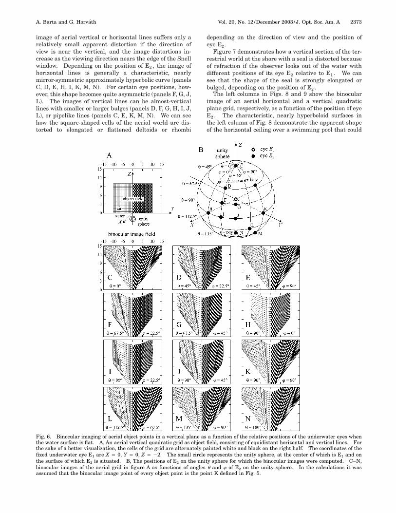
image of aerial vertical or horizontal lines suffers only arelatively small apparent distortion if the direction ofview is near the vertical, and the image distortions in-crease as the viewing direction nears the edge of the Snellwindow. Depending on the position of E2 , the image ofhorizontal lines is generally a characteristic, nearlymirror-symmetric approximately hyperbolic curve (panelsC, D, E, H, I, K, M, N). For certain eye positions, how-ever, this shape becomes quite asymmetric (panels F, G, J,L). The images of vertical lines can be almost-verticallines with smaller or larger bulges (panels D, F, G, H, I, J,L), or pipelike lines (panels C, E, K, M, N). We can seehow the square-shaped cells of the aerial world are dis-torted to elongated or flattened deltoids or rhombi
depending on the direction of view and the position ofeye E2 .
Figure 7 demonstrates how a vertical section of the ter-restrial world at the shore with a seal is distorted becauseof refraction if the observer looks out of the water withdifferent positions of its eye E2 relative to E1 . We cansee that the shape of the seal is strongly elongated orbulged, depending on the position of E2 .
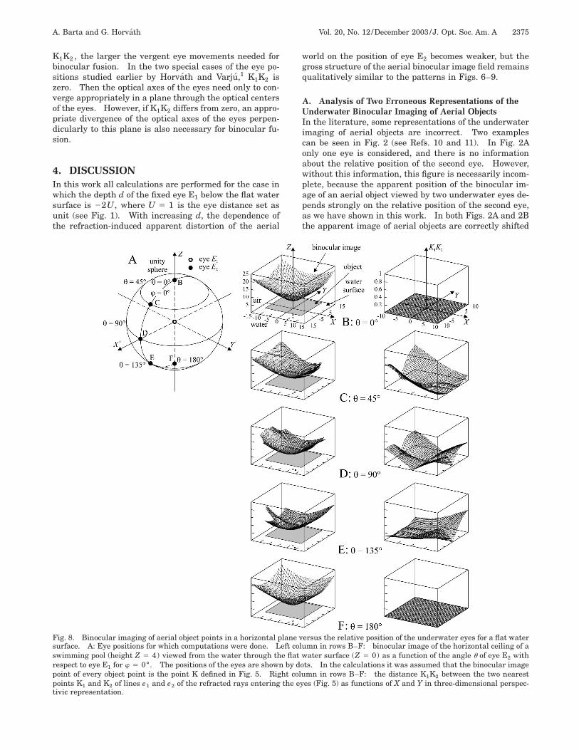
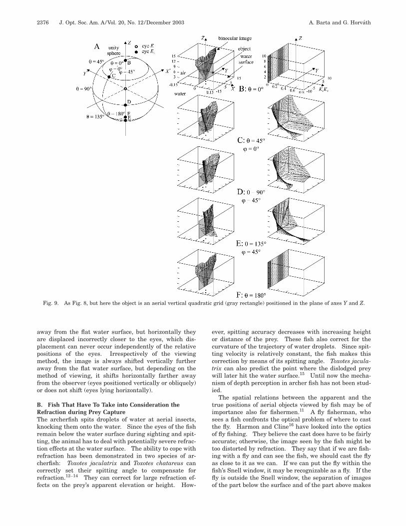
The left columns in Figs. 8 and 9 show the binocularimage of an aerial horizontal and a vertical quadraticplane grid, respectively, as a function of the position of eyeE2 . The characteristic, nearly hyperboloid surfaces inthe left column of Fig. 8 demonstrate the apparent shapeof the horizontal ceiling over a swimming pool that could
Fig. 6. Binocular imaging of aerial object points in a vertical plane as a function of the relative positions of the underwater eyes whenthe water surface is flat. A, An aerial vertical quadratic grid as object field, consisting of equidistant horizontal and vertical lines. Forthe sake of a better visualization, the cells of the grid are alternately painted white and black on the right half. The coordinates of thefixed underwater eye E1 are X 5 0, Y 5 0, Z 5 22. The small circle represents the unity sphere, at the center of which is E1 and onthe surface of which E2 is situated. B, The positions of E2 on the unity sphere for which the binocular images were computed. C–N,binocular images of the aerial grid in figure A as functions of angles u and w of E2 on the unity sphere. In the calculations it wasassumed that the binocular image point of every object point is the point K defined in Fig. 5.

2374 J. Opt. Soc. Am. A/Vol. 20, No. 12 /December 2003 A. Barta and G. Horvath
Fig. 7. As Fig. 6, but here the right half of the vertical grid is replaced by a picture representing a vertical section of the terrestrialworld with a seal lying on the shore, and the calculation of the Y and Z coordinates of the binocular image point K was performed forevery pixel (as object point) of this picture (pixel number 5 800 3 600 5 480,000).
be seen from the water as a function of the position of E2 .For a certain arrangement of eyes, the middle part of oneside of the quadratic grid is distorted in such a way thatthe image becomes oar shaped (panel E). We can see inthe left column of Fig. 9 that for certain eye positions(panels C–E) the binocular image of an aerial verticalgrid is not a plane but is a slightly curved surface differ-ing more or less from the plane of the aerial vertical objectgrid. At other positions of eye E2 , the binocular image
remains exactly two dimensional, and the plane of the im-age is parallel to the original vertical grid (panels B, F).
The right columns in Figs. 8 and 9 show the minimumdistance K1K2 between the two avoiding refracted rays oflight e1 and e2 extrapolated backward and entering theeyes E1 and E2 as a function of the position of E2 . At thebisecting point of section K1K2 the binocular image pointK of an aerial object point O is formed (Fig. 5) if binocularfusion is performed. The greater this minimum distance
A. Barta and G. Horvath Vol. 20, No. 12 /December 2003 /J. Opt. Soc. Am. A 2375
K1K2 , the larger the vergent eye movements needed forbinocular fusion. In the two special cases of the eye po-sitions studied earlier by Horvath and Varju,1 K1K2 iszero. Then the optical axes of the eyes need only to con-verge appropriately in a plane through the optical centersof the eyes. However, if K1K2 differs from zero, an appro-priate divergence of the optical axes of the eyes perpen-dicularly to this plane is also necessary for binocular fu-sion.
4. DISCUSSIONIn this work all calculations are performed for the case inwhich the depth d of the fixed eye E1 below the flat watersurface is 22U, where U 5 1 is the eye distance set asunit (see Fig. 1). With increasing d, the dependence ofthe refraction-induced apparent distortion of the aerial
world on the position of eye E2 becomes weaker, but thegross structure of the aerial binocular image field remainsqualitatively similar to the patterns in Figs. 6–9.
A. Analysis of Two Erroneous Representations of theUnderwater Binocular Imaging of Aerial ObjectsIn the literature, some representations of the underwaterimaging of aerial objects are incorrect. Two examplescan be seen in Fig. 2 (see Refs. 10 and 11). In Fig. 2Aonly one eye is considered, and there is no informationabout the relative position of the second eye. However,without this information, this figure is necessarily incom-plete, because the apparent position of the binocular im-age of an aerial object viewed by two underwater eyes de-pends strongly on the relative position of the second eye,as we have shown in this work. In both Figs. 2A and 2Bthe apparent image of aerial objects are correctly shifted
Fig. 8. Binocular imaging of aerial object points in a horizontal plane versus the relative position of the underwater eyes for a flat watersurface. A: Eye positions for which computations were done. Left column in rows B–F: binocular image of the horizontal ceiling of aswimming pool (height Z 5 4) viewed from the water through the flat water surface (Z 5 0) as a function of the angle u of eye E2 withrespect to eye E1 for w 5 0°. The positions of the eyes are shown by dots. In the calculations it was assumed that the binocular imagepoint of every object point is the point K defined in Fig. 5. Right column in rows B–F: the distance K1K2 between the two nearestpoints K1 and K2 of lines e1 and e2 of the refracted rays entering the eyes (Fig. 5) as functions of X and Y in three-dimensional perspec-tivic representation.
2376 J. Opt. Soc. Am. A/Vol. 20, No. 12 /December 2003 A. Barta and G. Horvath
Fig. 9. As Fig. 8, but here the object is an aerial vertical quadratic grid (gray rectangle) positioned in the plane of axes Y and Z.
away from the flat water surface, but horizontally theyare displaced incorrectly closer to the eyes, which dis-placement can never occur independently of the relativepositions of the eyes. Irrespectively of the viewingmethod, the image is always shifted vertically furtheraway from the flat water surface, but depending on themethod of viewing, it shifts horizontally farther awayfrom the observer (eyes positioned vertically or obliquely)or does not shift (eyes lying horizontally).
B. Fish That Have To Take into Consideration theRefraction during Prey CaptureThe archerfish spits droplets of water at aerial insects,knocking them onto the water. Since the eyes of the fishremain below the water surface during sighting and spit-ting, the animal has to deal with potentially severe refrac-tion effects at the water surface. The ability to cope withrefraction has been demonstrated in two species of ar-cherfish: Toxotes jaculatrix and Toxotes chatareus cancorrectly set their spitting angle to compensate forrefraction.12–14 They can correct for large refraction ef-fects on the prey’s apparent elevation or height. How-
ever, spitting accuracy decreases with increasing heightor distance of the prey. These fish also correct for thecurvature of the trajectory of water droplets. Since spit-ting velocity is relatively constant, the fish makes thiscorrection by means of its spitting angle. Toxotes jacula-trix can also predict the point where the dislodged preywill later hit the water surface.15 Until now the mecha-nism of depth perception in archer fish has not been stud-ied.
The spatial relations between the apparent and thetrue positions of aerial objects viewed by fish may be ofimportance also for fishermen.11 A fly fisherman, whosees a fish confronts the optical problem of where to castthe fly. Harmon and Cline16 have looked into the opticsof fly fishing. They believe the cast does have to be fairlyaccurate; otherwise, the image seen by the fish might betoo distorted by refraction. They say that if we are fish-ing with a fly and can see the fish, we should cast the flyas close to it as we can. If we can put the fly within thefish’s Snell window, it may be recognizable as a fly. If thefly is outside the Snell window, the separation of imagesof the part below the surface and of the part above makes
A. Barta and G. Horvath Vol. 20, No. 12 /December 2003 /J. Opt. Soc. Am. A 2377
the fly look less like a fly. The compression of the imageof the part above the surface may even make that part sosmall that it is lost in the clutter at the edge of the Snellwindow.
ACKNOWLEDGMENTSThis research was supported by a Humboldt fellowshipfrom the German Alexander von Humboldt foundationand an Istvan Szechenyi scholarship from the HungarianMinistry of Education to G. Horvath. Many thanks aredue to one reviewer for constructive comments.
The e-mail address of the corresponding author, GaborHorvath is [email protected].
REFERENCES1. G. Horvath and D. Varju, ‘‘On the structure of the aerial vi-
sual field of aquatic animals distorted by refraction,’’ Bull.Math. Biol. 53, 425–441 (1991).
2. D. Regan, ed., Binocular Vision, Vol. 9 of Vision and VisualDysfunction, J. R. Cronly-Dillon, gen. ed. (MacMillan, NewYork, 1991).
3. I. P. Howard and B. J. Rogers, Binocular Vision and Stere-opsis (Oxford U. Press, Oxford, UK, 1995).
4. G. Horvath and D. Varju, ‘‘Geometric optical investigationof the underwater visual field of aerial animals,’’ Math. Bio-sci. 102, 1–19 (1990).
5. G. Horvath, K. Buchta, and D. Varju, ‘‘Looking into the wa-ter with oblique head tilting: revision of the aerial binocu-lar imaging of underwater objects,’’ J. Opt. Soc. Am. A 20,
1120–1131 (2003).6. D. L. Shealy and D. G. Burkhard, ‘‘Flux density for ray
propagation in discrete index media expressed in terms ofthe intrinsic geometry of the deflecting surface,’’ Opt. Acta20, 287–301 (1973).
7. D. L. Shealy and D. G. Burkhard, ‘‘Analytical illuminancecalculation in a multi-interface optical system,’’ Opt. Acta22, 485–501 (1975).
8. G. Silva-Ortigoza, J. Castro-Ramos, and A. Cordero-Davila,‘‘Exact calculation of the circle of least confusion of a rota-tionally symmetric mirror. II,’’ Appl. Opt. 40, 1021–1028(2001).
9. G. Silva-Ortigoza, M. Marciano-Melchor, O. Carvente-Munoz, and R. Silva-Ortigoza, ‘‘Exact computation of thecaustic associated with the evolution of an aberrated wave-front,’’ J. Opt. A Pure Appl. Opt. 4, 358–365 (2002).
10. E. Schwartz, ‘‘Konnen ‘blinde’ Fische sehen? Fische habeneinen sechsten Sinn,’’ Aquarien Magazin July 1969, 272–275.
11. J. Walker, ‘‘What is a fish’s view of a fisherman and the flyhe has cast on the water?’’ Sci. Am. 250(3), 108–113 (1984).
12. K. H. Luling, ‘‘The archer fish,’’ Sci. Am. 209(1), 100–108(1963).
13. M. Bekoff and R. Dorr, ‘‘Predation by ‘shooting’ in archer-fish, Toxotes jaculatrix: accuracy and sequences,’’ Bull.Psychon. Soc. 7, 167–168 (1976).
14. L. M. Dill, ‘‘Refraction and the spitting behaviour of the ar-cherfish (Toxotes chatareus),’’ Behav. Ecol. Sociobiol. 2, 169–184 (1977).
15. S. Rossel, J. Corlija, and S. Schuster, ‘‘Predicting three-dimensional target motion: how archer fish determinewhere to catch their dislodged prey,’’ J. Exp. Biol. 205,3321–3326 (2002).
16. R. Harmon and J. Cline, ‘‘At the edge of the window,’’ RodReel, July 1980, pp. 41–45.