Design Modeling, Simulation of Spur Gear; Analysis of Spur...
12
International Journal of Engineering Research and Development e-ISSN: 2278-067X, p-ISSN: 2278-800X, www.ijerd.com Volume 12, Issue 1 (January 2016), PP.56-67 56 Design Modeling, Simulation of Spur Gear; Analysis of Spur Gears Engr . Rufus Ogbuka Chime. FCAI, Engr.Samuel I.Ukwuaba FNSE, FNIMecE Department of Mechanical Engineering Institute of Management and Technology, Pmb 1079, Enugu Department of Mechanical Engrg Petroleum Training Institute Effurun Delta State Abstract:- The range of computer applications in engineering design covers procedures from preliminary conceptual design to the production of manufacturing drawings and specifications. Most computer applications intended for production use can be classified into five or more major categories: analysis, computer-aided drafting and design, geometric modeling, data base management systems, and artificial intelligence. Gears are machine elements that transmit angular motion and power by the successive engagement of teeth on their periphery. They constitute an economical method for such transmission, particularly if power levels or accuracy requirements are high. Spur gears are the most common variety and the most economical to manufacture.. Axes of mating gears are parallel. Spur gears are used to transmit rotary motion between parallel shafts. They are cylindrical, and the teeth are straight and parallel to the axis of rotation. The pinion is the smaller of two mating gears; the larger is called the gear or the wheel. The scope of this work includes, to design, model and simulate Spur Gear, to select Gear materials ,to analysis spur gears also to detailed factor safety in design Computer aided design uses the mathematical and graphic processing power of the computer to assist the engineer in the creatoion, modification, analysis, and designs many factors have contributed to CAD technology becoming the necessary tool in the engineering technical data base, CAD combines the characteristic of designer and computer that are best applicable to the design process, the combination of human creativity with computer technology provides the design efficiency that has made CAD such as popular design tool. Gears are useful when the following kinds of power or motion transmission are required: (1) a change in speed of rotation, (2) a multiplication or division of torque or magnitude of rotation, (3) a change in direction of rotation, (4) conversion from rotational to linear motion or vice versa (rack gears), (5) a change in the angular orientation of the rotational motion (bevel gears), and (6) an offset or change in location of the rotating motion. I. INTRODUCTION A gear or cogwheel is a rotating machine part having cut teeth, or cogs, which mesh with another toothed part to transmit torque, in most cases with teeth on the one gear being of identical shape, and often also with that shape on the other gear.Two or more gears working in a sequence (train) are called a gear train or, in many cases, a transmission; such gear arrangements can produce a mechanical advantage through a gear ratio and thus may be considered a simple machine Shown In Fig 11-12. Geared devices can change the speed, torque, and direction of a power source. The most common situation is for a gear to mesh with another gear; however, a gear can also mesh with a non-rotating toothed part, called a rack, thereby producing translation instead of rotation. Early examples of gears date from the 4th century BCE in China (Zhan Guo times - Late East Zhou dynasty), which have been preserved at the Luoyang Museum of Henan Province, China. The earliest gears in Europe were circa CE 50 by Hero of Alexandria, but they can be traced back to the Greek mechanics of the Alexandrian school in the 3rd century BCE and were greatly developed by the Greek polymath Archimedes (287–212 BCE). Examples of further development include: Ma Jun (c. 200–265 CE) used gears as part of a south-pointing chariot. The Antikythera mechanism is an example of a very early and mili, and other application of water mill often used gears intricate geared device, designed to calculate astronomical positions. Its time of construction is now estimated between 150 and 100 BCE. The water-powered grain-mill, the water-powered saw mill, fulling . The first mechanical clocks were built in CE 725. The 1386 Salisbury cathedral clock may be the world's oldest working mechanical clock. CAD has its roots in interactive computer graphics. Before the CAD era, engineering drawings were prepared manually on paper using pencils and drafting instruments on a drafting table. The advent of interactive computer graphics replaced the drafting table with a computer monitor and the pencil with an input device such as a light pen or mouse. Instead of using physical drafting instruments, software commands and icons on the computer display are used. The drawing can be created, modified, copied, and transformed using the software tools. At the time, CAD stood for computer-aided drafting. Drafting was confined to 2D because of the paper limitation. With the computer, such limitation is removed. Three-dimensional CAD systems were developed in
Transcript of Design Modeling, Simulation of Spur Gear; Analysis of Spur...
International Journal of Engineering Research and Development
e-ISSN: 2278-067X, p-ISSN: 2278-800X, www.ijerd.com
Volume 12, Issue 1 (January 2016), PP.56-67
56
Design Modeling, Simulation of Spur Gear;
Analysis of Spur Gears
Engr . Rufus Ogbuka Chime. FCAI, Engr.Samuel I.Ukwuaba FNSE, FNIMecE Department of Mechanical Engineering Institute of Management and Technology, Pmb 1079, Enugu
Department of Mechanical Engrg Petroleum Training Institute Effurun Delta State
Abstract:- The range of computer applications in engineering design covers procedures from preliminary
conceptual design to the production of manufacturing drawings and specifications. Most computer applications
intended for production use can be classified into five or more major categories: analysis, computer-aided
drafting and design, geometric modeling, data base management systems, and artificial intelligence. Gears are
machine elements that transmit angular motion and power by the successive engagement of teeth on their
periphery. They constitute an economical method for such transmission, particularly if power levels or accuracy
requirements are high. Spur gears are the most common variety and the most economical to manufacture.. Axes
of mating gears are parallel. Spur gears are used to transmit rotary motion between parallel shafts. They are
cylindrical, and the teeth are straight and parallel to the axis of rotation. The pinion is the smaller of two mating
gears; the larger is called the gear or the wheel. The scope of this work includes, to design, model and simulate
Spur Gear, to select Gear materials ,to analysis spur gears also to detailed factor safety in design Computer
aided design uses the mathematical and graphic processing power of the computer to assist the engineer in the
creatoion, modification, analysis, and designs many factors have contributed to CAD technology becoming the
necessary tool in the engineering technical data base, CAD combines the characteristic of designer and
computer that are best applicable to the design process, the combination of human creativity with computer
technology provides the design efficiency that has made CAD such as popular design tool. Gears are useful
when the following kinds of power or motion transmission are required: (1) a change in speed of rotation, (2) a
multiplication or division of torque or magnitude of rotation, (3) a change in direction of rotation, (4) conversion
from rotational to linear motion or vice versa (rack gears), (5) a change in the angular orientation of the
rotational motion (bevel gears), and (6) an offset or change in location of the rotating motion.
I. INTRODUCTION A gear or cogwheel is a rotating machine part having cut teeth, or cogs, which mesh with another
toothed part to transmit torque, in most cases with teeth on the one gear being of identical shape, and often also
with that shape on the other gear.Two or more gears working in a sequence (train) are called a gear train or, in
many cases, a transmission; such gear arrangements can produce a mechanical advantage through a gear ratio
and thus may be considered a simple machine Shown In Fig 11-12. Geared devices can change the speed,
torque, and direction of a power source. The most common situation is for a gear to mesh with another gear;
however, a gear can also mesh with a non-rotating toothed part, called a rack, thereby producing translation
instead of rotation. Early examples of gears date from the 4th century BCE in China (Zhan Guo times - Late
East Zhou dynasty), which have been preserved at the Luoyang Museum of Henan Province, China. The earliest
gears in Europe were circa CE 50 by Hero of Alexandria, but they can be traced back to the Greek mechanics of
the Alexandrian school in the 3rd century BCE and were greatly developed by the Greek polymath Archimedes
(287–212 BCE). Examples of further development include: Ma Jun (c. 200–265 CE) used gears as part of a
south-pointing chariot.
The Antikythera mechanism is an example of a very early and mili, and other application of water mill
often used gears intricate geared device, designed to calculate astronomical positions. Its time of construction is
now estimated between 150 and 100 BCE. The water-powered grain-mill, the water-powered saw mill, fulling .
The first mechanical clocks were built in CE 725. The 1386 Salisbury cathedral clock may be the world's oldest
working mechanical clock.
CAD has its roots in interactive computer graphics. Before the CAD era, engineering drawings were
prepared manually on paper using pencils and drafting instruments on a drafting table. The advent of interactive
computer graphics replaced the drafting table with a computer monitor and the pencil with an input device such
as a light pen or mouse. Instead of using physical drafting instruments, software commands and icons on the
computer display are used. The drawing can be created, modified, copied, and transformed using the software
tools. At the time, CAD stood for computer-aided drafting. Drafting was confined to 2D because of the paper
limitation. With the computer, such limitation is removed. Three-dimensional CAD systems were developed in

Design .Modeling, Simulation Of Spur Gear ; Analysis Of Spur Gears
57
the 1960s. In 3D CAD, objects are modeled using 3D coordinates (x, y, and z) instead of 2D coordinates (x and
y). The need for modeling parts and products with complex surfaces motivated the development of free-form
surface modelers.
II. GEAR MATERIALS Numerous nonferrous alloys, cast irons, powder-metallurgy and plastics are used in the manufacture of
gears. However, steels are most commonly used because of their high strength-to-weight ratio and low cost.
Plastic is commonly used where cost or weight is a concern. A properly designed plastic gear can replace steel
in many cases because it has many desirable properties, including dirt tolerance, low speed meshing, the ability
to "skip" quite well and the ability to be made with materials that don't need additional lubrication.
Manufacturers have used plastic gears to reduce costs in consumer items including copy machines, optical
storage devices, cheap dynamos, consumer audio equipment, servo motors, and printers. Another advantage of
the use of plastics, formerly (such as in the 1980s), was the reduction of repair costs for certain expensive
machines. In cases of severe jamming (as of the paper in a printer), the plastic gear teeth would be torn free of
their substrate, allowing the drive mechanism to then spin freely (instead of damaging itself by straining against
the jam). This use of "sacrificial" gear teeth avoided destroying the much more expensive motor and related
parts. This method has been superseded, in more recent designs, by the use of clutches and torque- or current-
limited motors.
III. SUITABLE MATERIALS FOR GEARS Sufficient strength to transmit the power involved is a first requisite for any gear material.
Machinability is also important for machined gears, for two reasons: A considerable amount of metal removal is
involved when gears are machined, and it is easier to achieve precision of machining and smooth surface
finishes (which are important in gears) when the metal used has favorable machinability ratings. Other
properties that are almost always desirable and may be necessary for certain applications are corrosion
resistance, dimensional stability, impact strength, light weight, high temperature resistance, heat treatability,
wear resistance, natural lubricity or compatibility with lubricants, noise-damping properties (or limited noise-
generating properties), and (lest we forget) low cost.
DESIGN RECOMMENDATIONS
The closely dimensioned and standardized configuration inherent in the function of gears severely
limits the latitude of the designer in selecting a low-cost alternative design. Nevertheless, there are choices that
the designer can make that will have a bearing on the cost and performance of gear components. Some points
for consideration, applicable to machined, molded, cast, formed, or stamped gears, are the following:
1. Normally, the coarsest-pitch gear system that performs the required function will be the most economical to
produce. The designer, if given a choice between finepitch gearing and coarse-pitch gearing and provided
operating requirements permit, should choose the coarser-pitch system.
2. Helical, spiral, and hypoid systems are more difficult and costly to manufacture than straight-tooth designs.
Straight-tooth systems should be specified unless noise or other considerations necessitate a helical
configuration.
3. Dimensional tolerances, as controlled by AGMA or DIN gear numbers and permissible tooth-to-tooth and
total cumulative variations and surface finishes, should be as liberal as the function of the gears permits. Gears,
like other manufactured components, are subject to geometrically increased costs as tolerances are reduced
APPLYING COMPUTERS TO DESIGN
No other idea or device has impacted engineering as computers have. All engineering disciplines
routinely use computer for calculation, analysis, design and simulation .Many of the individual tasks within the
overall design process can be performed using a computer. As each of these tasks is made more efficient, the
efficiency of the overall process increases as well. The computer is especially well suited to design in four areas,
which correspond to the latter four stages of the general design process. Computers function in the design
process through geometric modeling capabilities, engineering analysis calculations, automated testing
procedures, and automated drafting.
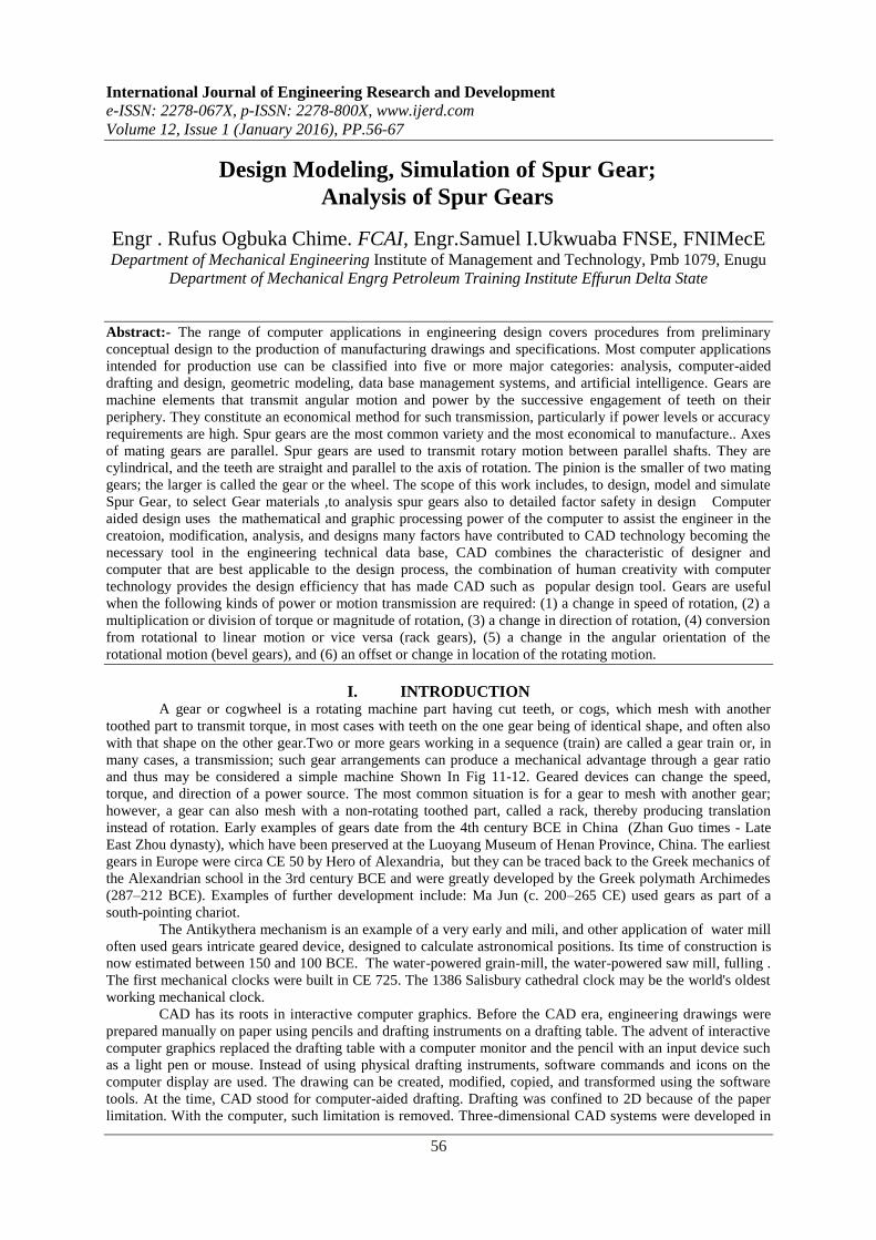
STATIC ANALYSIS determines reaction forces at the joint positions of resting when a constant load is
applied. As long as zero velocity is assumed, static analysis can be performed on mechanisms at different points
of their range of motion. Static analysis allows the designer to determine the reaction forces on whole
mechanical systems as well as interconnection forces transmitted to their individual joints.
The data extracted from static analysis can be useful in determining compatibility with the various
criteria set out in the problem definition. These criteria may include reliability, fatigue, and performance
Design .Modeling, Simulation Of Spur Gear ; Analysis Of Spur Gears
58
considerations to be analyzed through stress analysis methods fig 3. Detailed the Region with FOS (factor of
safety) value less than 1 in red
EXPERIMENTAL ANALYSIS involves fabricating a prototype and subjecting it to various experimental
methods. Although this usually takes place in the later stages of design, CAD systems enable the designer to
make more effective use of experimental data, especially where analytical methods are thought to be unreliable
for the given model. CAD also provides a useful platform for incorporating experimental results
Modelling and simulation of spur gear
Fig: 1 spur gear Fig: 2 Solid Mesh
Fig: 3 Spur Gear under Stress Fig: 4 Displacement
Fig: 5 Deformed Shape Fig: 6 Factor of Safety

Design .Modeling, Simulation Of Spur Gear ; Analysis Of Spur Gears
59
Fig: 7 Spur Gears with Blind Hole Fig: 8 Final Design of Spur Gears
Fig: 9 View of Wheel Fig: 10 View of Pinion
Fig 11.Spur Gears Arrangement Fig: 12 Spur Gears Rotation
Design .Modeling, Simulation Of Spur Gear ; Analysis Of Spur Gears
60
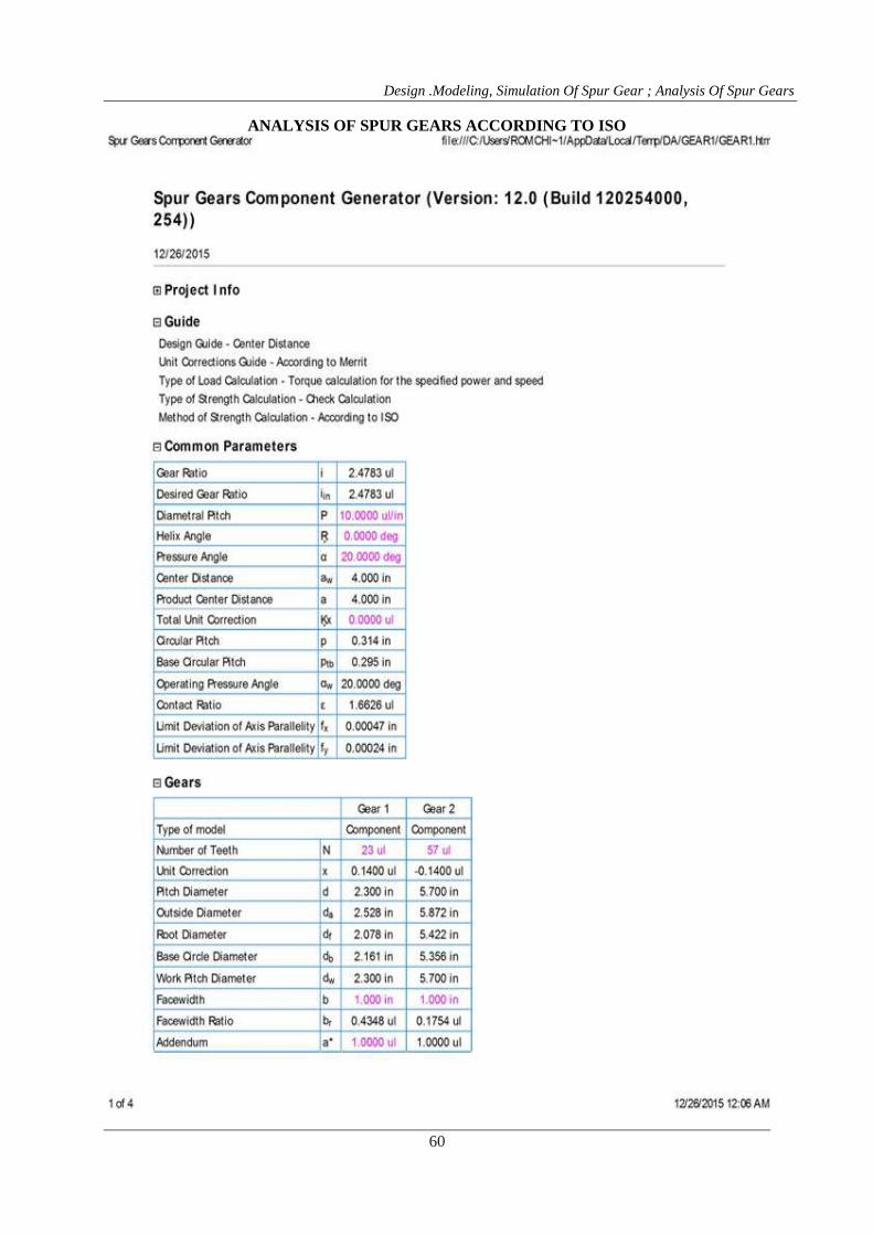
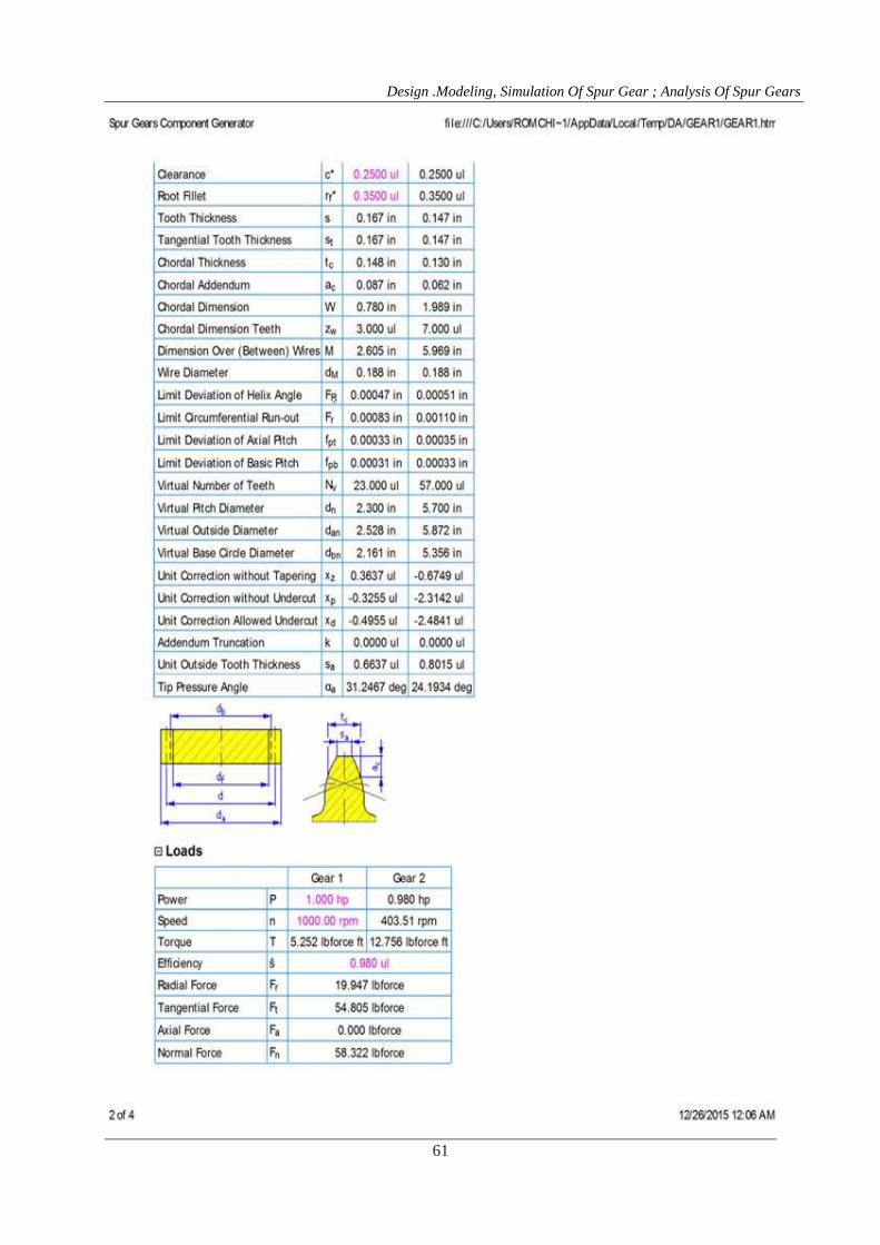
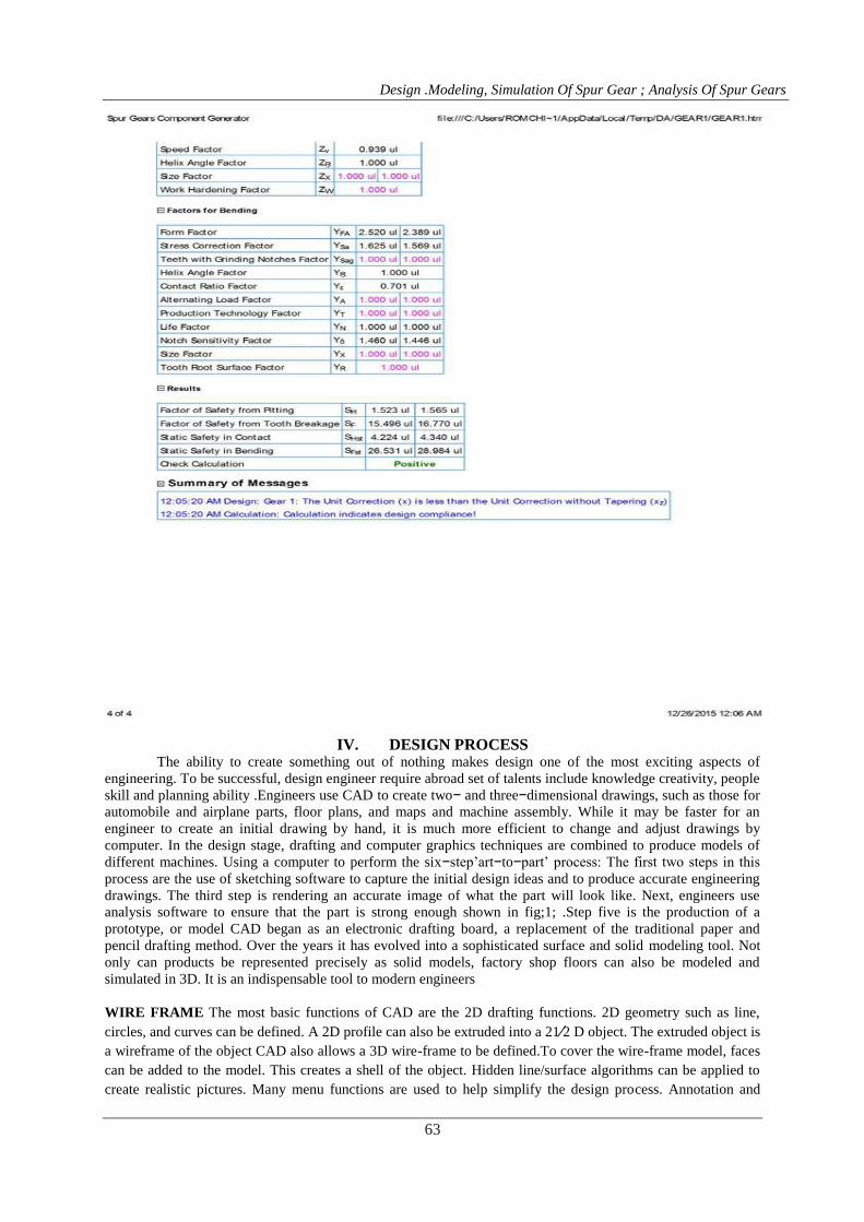
ANALYSIS OF SPUR GEARS ACCORDING TO ISO
Design .Modeling, Simulation Of Spur Gear ; Analysis Of Spur Gears
61

Design .Modeling, Simulation Of Spur Gear ; Analysis Of Spur Gears
62
Design .Modeling, Simulation Of Spur Gear ; Analysis Of Spur Gears
63
IV. DESIGN PROCESS The ability to create something out of nothing makes design one of the most exciting aspects of
engineering. To be successful, design engineer require abroad set of talents include knowledge creativity, people
skill and planning ability .Engineers use CAD to create two− and three−dimensional drawings, such as those for
automobile and airplane parts, floor plans, and maps and machine assembly. While it may be faster for an
engineer to create an initial drawing by hand, it is much more efficient to change and adjust drawings by
computer. In the design stage, drafting and computer graphics techniques are combined to produce models of
different machines. Using a computer to perform the six−step’art−to−part’ process: The first two steps in this
process are the use of sketching software to capture the initial design ideas and to produce accurate engineering
drawings. The third step is rendering an accurate image of what the part will look like. Next, engineers use
analysis software to ensure that the part is strong enough shown in fig;1; .Step five is the production of a
prototype, or model CAD began as an electronic drafting board, a replacement of the traditional paper and
pencil drafting method. Over the years it has evolved into a sophisticated surface and solid modeling tool. Not
only can products be represented precisely as solid models, factory shop floors can also be modeled and
simulated in 3D. It is an indispensable tool to modern engineers
WIRE FRAME The most basic functions of CAD are the 2D drafting functions. 2D geometry such as line,
circles, and curves can be defined. A 2D profile can also be extruded into a 21 ⁄2 D object. The extruded object is
a wireframe of the object CAD also allows a 3D wire-frame to be defined.To cover the wire-frame model, faces
can be added to the model. This creates a shell of the object. Hidden line/surface algorithms can be applied to
create realistic pictures. Many menu functions are used to help simplify the design process. Annotation and
Design .Modeling, Simulation Of Spur Gear ; Analysis Of Spur Gears
64
dimensioning are also supported. Text and dimension symbols can be placed anywhere on the drawing, at any
angle, and at any size.
V. MODELLING Modeling is the process of producing a model; a model is a representation of the construction and
working of some system of interest as shown in fig 7-10. A model is similar to but simpler than the system it
represents. One purpose of a model is to enable the analyst to predict the effect of changes to the system. On the
one hand, a model should be a close approximation to the real system and incorporate most of its salient
features. On the other hand, it should not be so complex that it is impossible to understand and experiment with
it. A good model is a judicious tradeoff between realism and simplicity. Simulation practitioners recommend
increasing the complexity of a model iteratively. An important issue in modeling is model validity. Model
validation techniques include simulating the model under known input conditions and comparing model output
with system output.
Generally, a model intended for a simulation study is a mathematical model developed with the help of
simulation software. Mathematical model classifications include deterministic (input and output variables are
fixed values) or stochastic (at least one of the input or output variables is probabilistic); static (time is not taken
into account) or dynamic (time-varying interactions among variables are taken into account). Typically,
simulation models are stochastic and dynamic
VI. SIMULATION A simulation of a system is the operation of a model of the system. The model can be reconfigured and
experimented with; usually, this is impossible, too expensive or impractical to do in the system it represents.
The operation of the model can be studied, and hence, properties concerning the behavior of the actual system or
its subsystem can be inferred. In its broadest sense, simulation is a tool to evaluate the performance of a system,
existing or proposed, under different configurations of interest and over long periods of real time. Simulation is
used before an existing system is altered or a new system built, to reduce the chances of failure to meet
specifications, to eliminate unforeseen bottlenecks, to prevent under or over-utilization of resources, and to
optimize system performance. For instance, simulation can be used to answer questions like:What is the best
design for a new network? What are the associated resource requirements? How will a telecommunication
network perform when the traffic load increases by 50%? How will new routing algorithm affect its
performance? Which network protocol optimizes network performance? What will be the impact of a link
failure? The subject of this tutorial is discrete event simulation in which the central assumption is that the
system changes instantaneously in response to certain discrete events. For instance, in an M/M/1 queue - a
single server queuing process in which time between arrivals and service time are exponential - an arrival causes
the system to change instantaneously. On the other hand, continuous simulators, like flight simulators and
weather simulators, attempt to quantify the changes in a system continuously over time in response to controls.
Discrete event simulation is less detailed (coarser in its smallest time unit) than continuous simulation but it is
much simpler to implement, and hence, is used in a wide variety of situations.
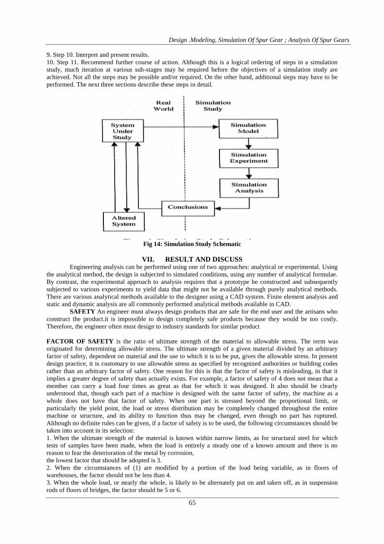
Figure, 2-6 is a schematic of a simulation study. The iterative nature of the process is indicated by the
system under study becoming the altered system which then becomes the system under study and the cycle
repeats. In a simulation study, human decision making is required at all stages, namely, model development,
experiment design, output analysis, conclusion formulation, and making decisions to alter the system under
study. The only stage where human intervention is not required is the running of the simulations, which most
simulation software packages perform efficiently. The important point is that powerful simulation software is
merely a hygiene factor - its absence can hurt a simulation study but its presence will not ensure success.
Experienced problem formulators and simulation modelers and analysts are indispensable for a successful
simulation study.
The steps involved in developing a simulation model, designing a simulation experiment, and performing
simulation analysis are:
1. Step 1. Identify the problem.
2. Step 2. Formulate the problem.
3. Step 3. Collect and process real system data.
4. Step 4. Formulate and develop a model.
5. Step 5. Validate the model.
6. Step 6. Document model for future use.
7. Step 7. Select appropriate experimental design. Step 8. Establish experimental conditions for.
8. Step 9. Perform simulation runs.
Design .Modeling, Simulation Of Spur Gear ; Analysis Of Spur Gears
65
9. Step 10. Interpret and present results.
10. Step 11. Recommend further course of action. Although this is a logical ordering of steps in a simulation
study, much iteration at various sub-stages may be required before the objectives of a simulation study are
achieved. Not all the steps may be possible and/or required. On the other hand, additional steps may have to be
performed. The next three sections describe these steps in detail.
Fig 14: Simulation Study Schematic
VII. RESULT AND DISCUSS Engineering analysis can be performed using one of two approaches: analytical or experimental. Using
the analytical method, the design is subjected to simulated conditions, using any number of analytical formulae.
By contrast, the experimental approach to analysis requires that a prototype be constructed and subsequently
subjected to various experiments to yield data that might not be available through purely analytical methods.
There are various analytical methods available to the designer using a CAD system. Finite element analysis and
static and dynamic analysis are all commonly performed analytical methods available in CAD.
SAFETY An engineer must always design products that are safe for the end user and the artisans who
construct the product.it is impossible to design completely safe products because they would be too costly.
Therefore, the engineer often must design to industry standards for similar product
FACTOR OF SAFETY is the ratio of ultimate strength of the material to allowable stress. The term was
originated for determining allowable stress. The ultimate strength of a given material divided by an arbitrary
factor of safety, dependent on material and the use to which it is to be put, gives the allowable stress. In present
design practice, it is customary to use allowable stress as specified by recognized authorities or building codes
rather than an arbitrary factor of safety. One reason for this is that the factor of safety is misleading, in that it
implies a greater degree of safety than actually exists. For example, a factor of safety of 4 does not mean that a
member can carry a load four times as great as that for which it was designed. It also should be clearly
understood that, though each part of a machine is designed with the same factor of safety, the machine as a
whole does not have that factor of safety. When one part is stressed beyond the proportional limit, or
particularly the yield point, the load or stress distribution may be completely changed throughout the entire
machine or structure, and its ability to function thus may be changed, even though no part has ruptured.
Although no definite rules can be given, if a factor of safety is to be used, the following circumstances should be
taken into account in its selection:
1. When the ultimate strength of the material is known within narrow limits, as for structural steel for which
tests of samples have been made, when the load is entirely a steady one of a known amount and there is no
reason to fear the deterioration of the metal by corrosion,
the lowest factor that should be adopted is 3.
2. When the circumstances of (1) are modified by a portion of the load being variable, as in floors of
warehouses, the factor should not be less than 4.
3. When the whole load, or nearly the whole, is likely to be alternately put on and taken off, as in suspension
rods of floors of bridges, the factor should be 5 or 6.
Design .Modeling, Simulation Of Spur Gear ; Analysis Of Spur Gears
66
4. When the stresses are reversed in direction from tension to compression, as in some bridge diagonals and
parts of machines, the factor should be not less than 6.
5. When the piece is subjected to repeated shocks, the factor should be not less than 10.
6. When the piece is subjected to deterioration from corrosion, the section should be sufficiently increased to
allow for a definite amount of corrosion before the piece is so far weakened by it as to require removal.
7. When the strength of the material or the amount of the load or both are uncertain, the factor should be
increased by an allowance sufficient to cover the amount of the uncertainty.
8. When the strains are complex and of uncertain amount, such as those in the crankshaft of a reversing engine,
a very high factor is necessary, possibly even as high as 40.
9. If the property loss caused by failure of the part may be large or if loss of life may result, as in a derrick
hoisting materials over a crowded street, the factor should be large.
VIII. CONCLUSION CAD combines the characteristic of designer and computer that are best applicable made CAD such as
popular design tool. CAD Has allowed the designer to bypass much of the Manuel drafting and analysis .
Simulation tools enable us to be creative and to quickly test new ideas that would be much more difficult, time-
consuming, and expensive to test in the lab. (Jeffrey D. Wilson, Nasa Glenn Research Center) It also help us
reduce cost and time-to-market by testing our designs on the computer rather than in the field. Many of the
individual tasks within the overall design process can be performed using a computer. As each of these tasks is
made more efficient, the efficiency of the overall process increases as well. The computer is well suited to
design in four areas, which correspond to the latter four stages of the general design process; Computers
function in the design process through geometric modeling capabilities, engineering analysis calculations,
testing procedures, and automated drafting, From the result of the testing and the affordability in terms of cost, it
can be concluded that the project is successful. Therefore software design should be encouraged in our
institution of higher learning base on the following facts, long product development, countless trial and error,
and accountability and limited profitability
REFERENCES [1]. Childs,, T.H.C.; Maekawa, K.; Obikawa, T.; Yamane, Y. ” Metal Machining -Theory and
Applications”, Elsevier Dec 7, 200, ISBN 0-340-69159-X
[2]. Holubář, P., Šíma, M., Zindulka, O., Technologie Úpravy Nástrojů Před Povlakováním, MM
průmyslové spektrum, č. 9
[3]. OBERG, Erik; Jones, Franklin D.; Horton, Holbrook L,Ryffel, Henry H., Machinery's Handbook
(27thEdition) & Guide to Machinery's Handbook, Industrial Press, Sep 19, 2005
[4]. Zetek, M.; Škarda, J.; Kříž, A.; Sosnová, M.; Hájek, J.; Podaný, P. New Types Of Thin Layers And
new trends in PVD technologies. In ICPM 2005. Wien : Abteilung Austauschbau und Messtechnik,
2005. s. 337-343. ISBN 3-901-888-31-4
[5]. Law, A. M., and M. G. McComas. 1991. Secrets of Successful Simulation Studies, Proceedings of
the1991 Winter Simul ation Conference, ed. J. M.Charnes, D. M. Morrice, D. T. Brunner, and J.
J.Swain, 21−27. Institute of Electrical and Electroni cs Engineers, Piscataway, New Jersey
[6]. Mechanical Engineers' Handbook, 2nd ed., Edited By Kutz.
[7]. Ashok Kumar Gupta Dr.Vandana Somkuwar (2014) Spiral Gevel Gear And Development Generation
And Simulation Of Meshing And Tooth Contact Analysis (Tca)
[8]. Mark T.Holtzapple W.Dan Reece “Fundamental of Engineering”Taxas A&M University
[9]. Industrial Engineering handBook fifth Edition Edited by KJELL B. zandian co-sponsores by JMA,INC.
[10]. Koya O.A and Faborode M.O(2005) Mathematic al modeling of palm fruit cracking based on Hertzs
Theory˜Biosyst ems Engineering, Vol.91 No.4 pp 471− 7
[11]. Tugrul Özel and Taylan Altan(1998)Modeling Of High Speed Machining Processes For Predicting
Tool Forces, And Temperatures Using Fem Simulations
[12]. Cox, S.W. 1992. Simulation Studio™, in Proceedings of the 1992 Winter Simulation Conference, J. J.
Swain, D. Goldman, R.C. Crain, and J.R. Wilson, Eds., Association for Computing Machinery,
New York, 347–351.
[13]. Glavach, M.A. and Sturrock, D.T. 1993. Introduction to Siman/Cinema, in Proceedings of the 1993
[14]. Winter Simulation Conference, G.W. Evans, M. Mollaghasemi, E.C. Russell, and W.E. Biles, Eds.,
Association for Computing Machinery, New York, 190–192.
[15]. https://en.wikipedia.org/wiki/Spur_gear
[16]. (www.digitalengineeringlibrary.com)
[17]. Www.Gearseds.Com/Files/5.3.1_Gear_Terms- _Revs.Pdf

Design .Modeling, Simulation Of Spur Gear ; Analysis Of Spur Gears
67
[18]. Engr. Rufus O. Chime, Engr.Samuel I.Ukwuaba, Engr.Engr. Ukwu Nwachukwu Design Modelling and
Simulation of a Screw press Expeller for palm kernel oil extraction [International Engineering
Conference, Exhibition and Annual General meeting] NSE Proceedings, 2013 Banks, J. 1994.
Simulation software, paper presented as 1994 Winter Simulation Conference, Atlanta