· PDF fileProfile Design Functions Spec. Info. HBF-US110 Plastic round-type micro stroke...
14
L-170-6-C7567-C INA-0812 (MDOC) Revised publication, effective Dec. 2008. Superseding publication of L-170-6-C7567-B Jul. 2007. Specifications subject to change without notice. Mitsubishi Electric & Electronics USA, Inc., Elevator/Escalator Division Website: http://www.mitsubishielevator.com Email: [email protected] http://www.mitsubishi-elevator.com/
Transcript of · PDF fileProfile Design Functions Spec. Info. HBF-US110 Plastic round-type micro stroke...

��������� ������� ���������������� ���������� ���
L-170-6-C7567-C INA-0812 (MDOC)
Revised publication, effective Dec. 2008.Superseding publication of L-170-6-C7567-B Jul. 2007.
Specifications subject to change without notice.
Mitsubishi Electric & Electronics USA, Inc., Elevator/Escalator Division���� ������ ��� ! �"#� ������ ��$�� ! %&&% ��"'"(�)*�+�,-��..+�"�)/��0)" 1 &2 + �3�3�3
Website: http://www.mitsubishielevator.comEmail: [email protected]
http://www.mitsubishi-elevator.com/

2
Energy and space savingsHigh-efficiency transport mechanism
Comfortable, quiet rideSmooth door operation
Riding and boarding safetyHigh reliability
Mitsubishi Electric elevators and escalators are known for their exceptional comfort,
safety and efficiency. Our new machine-room-less elevators feature the improved comfort
and freedom of layout that sets Mitsubishi Electric apart.
Contents
Prof
ileD
esig
nFu
nctio
nsSp
ec.
Info
.
Car Signal Fixtures
Hall Signal Fixtures
P.7
P.8
Functions P.9
Basic Specifications
Car Hitch Beam
Entrance Layouts
P.13
P.19
P.21
P.3
P.5
The Evolution of Mitsubishi Quality
Freedom of Layout
P.23Important Informationon Elevator Planning
1

The slim control panel is packedwith advanced technologiessuch as VVVF, PWM and IPU.
The gearless traction machine with the new PM (permanent magnet) motor is packed with cutting-edge technology, such as our unique stator-core structure and built-in double brakes. This optimized motor design dramatically reduces the level of torque ripple for a smoothand quiet ride.
Our elevators include features designed to reduce the need for maintenance – such as double brakes built into the PM motor. During scheduled maintenance, equipment in the top of the hoistway is easily accessible from the maintenance platform on top of the elevator cage. In addition, Mitsubishi Electric's highly trained service personnel continually ensure that our elevators run smoothly and safely.
VVVF* Inverter Control has been adopted to ensure smoother and quieter door operations, thereby enhancing passenger safety and product reliability. Our innovative door operation system employs a highly efficient "one-chip RISC microcomputer" which detects the constant variations on each floor in the door load, the strength of the wind, and even sediment in the sill grooves. It adjusts the door open and close speeds, as well as the door motor torque as needed for each floor using the Auto Tuning function. The learning-capable Door Load Detector immediately reverses the doors when abnormal load is detected on the doors.
The high-accumulation LSI integrating digital control circuitry has significantly increased the speed of the computer processing, enabling precise control of the traction motor during acceleration and deceleration. This innovation delivers a quality ride with the least noise and vibration.
Control CPU PCB
More technological advances, such as the high-accumulation LSI and low-noise PWM inverter, enable the VVVF inverter to deliver smooth, high-precision control of the traction machine. In addition, the IPU (Integrated Power Unit) acts as a high-efficiency power supply circuit for the motor drive and, along with the PM motor, delivers greater energy savings. The adoption of the low-noise IGBT with faster switching speeds also contributes to further reduce the noise. The result is a more efficient, more reliable drive control.
Integrated power unit
Prof
ileD
esig
nFu
nctio
nsSp
ec.
Info
.
*VVVF: Variable Voltage Variable Frequency.
3 4

Mitsubishi Electric has succeeded in miniaturizing key elevator equipment. The gearless traction machine with PM motor is installed within the hoistway. This arrangement frees up space normally required for separate machine rooms or penthouses. Equipment is configured for easy maintenance from car top, and the entire compact system is optimally organized for performance and service.
The miniaturization of the traction machine, leading to the development of the gearless traction machine with PM motor enables a hoistway to include in the upper section the driving devices that were installed in a machine room. Besides that, the square area of the hoistway is almost the same as our conventional elevator, contributing to space saving in your building. All you have to think about in your planning now is a hoistway only*.
*NEC 2003 Article 620-71 and ASME A17.1 2004~A17.a-2005 Rule 2.7.6
stipulate that an elevator control panel must be installed outside the hoistway and thereby a separate room is required for control panels.
Prof
ileD
esig
nFu
nctio
nsSp
ec.
Info
.
GPM-IIILU(Conventional)
DIAMOND TRAC
Architects, builders, and even interior designers will appreciate the new design freedom that comes with the machine-room-less system. A machine room is no longer needed, as all machineries successfully fit into the hoistway, except the control panel, which can be placed wherever you like within a 98 feet 5 inch (30 meter) radius from the traction machine. Also, the load stress of our conventional elevator with a machine room applies on the building structure, whereas the guide rails of DIAMOND TRAC support as much as 75% of the stress, for building friendliness.
5 6

Hall Buttons
Faceplate
Call button
Response light
Graphic
LED lamp, yellow-orange when illuminated
Etching
Stainless steel hairline
Round-type micro stroke click buttonin gray plastic (HBF-US110, HBF-US210)
Round-type micro stroke click buttonin stainless steel (HBV-US110, HBV-US210)
Car Operating Panels Car Lantern
CBF-US110
Plastic round-typemicro stroke click button
(standard)
Smoky gray plastic, matt surface
Faceplate Stainless steel hairline
Digital LED dot display,orange when illuminated
Round-type micro stroke click buttonin gray plastic with milky white mark in centeras response light (CBF-US110)
LED lamp, yellow-orange when illuminated
Hall Lanterns
HLV-US210(standard)
HLV-US110(option)
Faceplate
Lighting
Stainless steel hairline
Clear acrylic, yellow-orange when UP sideis illuminated, and red when DOWN side is illuminated
Display panel
Direction andposition indicator
Car button
Response light
Braille plate Black plate with tactile floor name, symboland Braille next to car button
Clear acrylic with frosted finish, yellow-orange when UP side is illuminated, and red when DOWN side is illuminated
Faceplate Stainless steel hairline
Lighting
CBV-US110
CLV-US110(standard)
Stainless steel round-typemicro stroke click button
(option)
Round-type micro stroke click buttonin stainless steel (CBV-US110)
HBF-US210Plastic round-type
micro stroke click button(option)
HBV-US210Stainless steel round-typemicro stroke click button
(option)
Prof
ileD
esig
nFu
nctio
nsSp
ec.
Info
.Profile
Design
FunctionsSpec.
Info.
HBF-US110Plastic round-type
micro stroke click button(standard)
HBV-US110Stainless steel round-type
micro stroke click button(option)
7 8
Actual elevator color may differ slightly from that shown.

ProfileD
esignFunctions
Spec.Info.
Feature Description
To reduce passenger waiting time, cars which have finished service areautomatically directed to positions where they can respond to predictedhall calls as quickly as possible.
A floor which temporarily has the heaviest traffic will be served with higherpriority than other floors, but not to an extent that interferes withservice to other floors.
Cars are allocated to hall calls by considering the number of car calls that willreduce passenger waiting time in each hall and the travel time of each car.
Strategic Overall Spotting (SOHS)
Peak Traffic Control (PTC)
Car Travel Time Evaluation
Cars are allocated according to the predicted psychological waiting timefor each hall call. The rules evaluating psychological waiting time areautomatically changed in response to actual service conditions.
Psychological Waiting TimeEvaluation
Artificial expert knowledge, which has been programmed using"expert system" and "fuzzy logic", is applied to select the idealoperational rule for maximum efficiency of group control operations.
Expert System and Fuzzy Logic
GROUP CONTROL FEATURES
–
–
–
–
–
A car which is experiencing trouble is automatically withdrawn from groupcontrol operation to maintain overall group performance.
If one car cannot carry all waiting passengers because it is full, anothercar will automatically be assigned for the remaining passengers.
An operation by car controllers which automatically starts to maintainelevator operation, in the event that a microprocessor or transmissionline in the group controller has failed.
In case of earthquake detection, the elevator stops atthe nearest available floor and shuts down with the door open. (Detailed operation conforms to the local code.)
Earthquake Emergency Operation(EER-DS)
If the elevator doors do not open fully at a destination floor, the doorsclose and the car automatically moves to the next or nearest floor, wherethe doors will open.
A buzzer sounds to alert the passengers that the car is overloaded;the doors remain open and the car does not leave that floor until enoughpassengers exit the car.
Exclusive operation where a car is withdrawn from group control operation forindependent use, such as maintenance or repair, and responds only to car calls.
If a car has stopped between floors due to some equipment malfunction,the controller checks the cause, and if it is considered safe to move the car,the car will move to the nearest floor at a low speed and the doors will open.
When a car has responded to the final car call in one direction, the systemregards remaining calls in the other direction as errors and clears themfrom the memory.
Car Call Canceling (CCC)
Continuity of Service (COS)
Automatic HallCall Registration (FSAT)
Backup Operation for GroupControl Microprocessor (GCBK)
Next Landing (NXL)
Overload Holding Stop (OLH)
Safe Landing (SFL)
Independent Service (IND)
Feature Description 1Car2BC
2Car2BC
3-4Car AI-22
1Car2BC
2Car2BC
OPERATIONAL AND SERVICE FEATURES
Failure of non-contact door sensors is checked automatically, and ifa problem is diagnosed, the door-close timing is delayed and the closingspeed is reduced to maintain elevator service and ensure passenger safety.
Door load on each floor, which can depend on the type of hall door, ismonitored to adjust the door speed, thereby making it consistentthroughout all floors.
The doors slowly close when they have remained open for longerthan the preset period with alarm sound.
Should an obstacle prevent the doors from closing, the doors will repeatedly open and close until the obstacle is removed.
Closing doors can be re-opened by pressing the hall buttoncorresponding to the traveling direction of the car.
When excessive door load has been detected while opening or closing,the doors immediately move in the reverse direction.
Door Load Detector (DLD)
Door Sensor Self-Diagnosis (DODA)
Automatic Door SpeedControl (DSAC)
Door Nudging Feature (NDG)
Repeated Door-Close (RDC)
Re-open with Hall Button (ROHB)
DOOR OPERATION FEATURES
SIGNAL AND DISPLAY FEATURES
Call buttons that click softly when touched are fitted as standard.Car/Hall Click Type Call Buttons
Standard Features
If there are no calls for a specified period, the car lighting will automaticallyshut off to conserve energy.
–
–
–
–
In case of fire, the elevator performs firefighters’ emergency operation (Phase I and Phase II) conforming to the local code.
Firefighter's EmergencyOperation (FE)
EMERGENCY OPERATIONS AND FEATURES
Electronic chimes that sound to indicate that a car will soon arrive.(The chimes are mounted on the top and bottom of the car.)
A hall lantern, which corresponds to a car's service direction,flashes to indicate that the car will soon arrive.
Flashing Hall Lantern (FHL)
A synthetic voice (and/or buzzer) that alerts passengers inside a car tothe fact that elevator operation has been temporarily interrupted byoverloading or a similar cause. (Voice available only in English.)
Basic Announcement (AAN-B)
Electronic Doorman (EDM)Door open time is minimized using safety ray(s) or multi-beam door sensorsthat detect passengers boarding or exiting.
Notes: – = Not applicable # = Please consult us for lead times and details.
If there are no calls for a specified period, the car ventilation fan willautomatically be turned off to conserve energy.
If the number of registered car calls does not correspond to the car load,all calls are canceled to avoid unnecessary stops.
A fully loaded car bypasses hall calls in order to maintain maximumoperational efficiency.
Automatic Bypass (ABP)
–
–
Multi-Beam Door SensorMultiple infrared-light beams cover some 1800mm in height of the doors asthey close to detect passengers or objects. (Cannot be combined with SR feature.)
A system which allows communication between passengers inside a carand the building personnel.
Inter Communication System (ITP)
Prof
ileD
esig
nFu
nctio
nsSp
ec.
Info
.
3-4Car AI-22
9 10

Prof
ileD
esig
nFu
nctio
nsSp
ec.
Info
.Profile
Design
FunctionsSpec.
Info.
In case of power failure, a car equipped with this function automaticallymoves and stops at the nearest floor using a rechargeable battery,and the doors open to ensure passenger safety. (Max. allowable floor-to-floor distance is 10 meters.)
Each elevator's status and operations can be monitored and controlledusing an advanced Web-based technology which provides an interfacethrough personal computers. Special optional features, such as preparationof traffic statistics and analysis, are also available.
A panel installed in a building's supervisory room,which monitors and controls each elevator's status and operationsby remotely using indicators and switches provided on request.
In case of power failure, the elevator moves to the designated floorand opens the door to secure the safety of passengers. Then,the elevator shall serve by emergency power till normal power recovery. (Detailed operation conforms to the local code.)
Car lighting which turns on immediately when power fails to provide aminimum level of lighting within the car. (Choice of dry-cell battery or trickle-charger battery.)
Emergency Car Lighting (ECL)
Mitsubishi Emergency LandingDevice (MELD)
Mitsubishi Elevators & Escalators Monitoring and ControlSystem MelEye (WP-W)
Operation by Emergency powersource - Automatic (OEPS-AU)
Supervisory Panel (WP)
EMERGENCY OPERATIONS AND FEATURES
Information on elevator service such as the current floor or servicedirection that is heard by the passengers inside a car. (Voice guidance available only in English.)
Voice Guidance System (AAN-G)
SIGNAL AND DISPLAY FEATURES
Notes: – = Not applicable # = Please consult us for lead times and details.
Feature DescriptionFeature Description 1Car2BC
2Car2BC
Electronic chimes that sound to indicate that a car will soon arrive.(The chimes are mounted in each hall.)
To save energy, the number of service cars is automatically reduced tosome extent but not so much as to adversely affect passenger waiting time.
All cars in a bank automatically make a stop at a predetermined flooron every trip without being called.
Special cars, such as observation elevators and elevators with basementservice, are given higher priority to respond to hall calls. (Cannot be combined with Hall Position Indicators.)
Special floors, such as floors with VIP rooms or executive rooms, are givenhigher priority for car allocation when a call is made on those floors.(Cannot be combined with Hall Position Indicators.)
An available car always parks on the main floor with the doors open toreduce passenger waiting time.
This feature is effective for buildings with two main floors. The floordesignated as the "Main floor" in a group control operation can be changedas necessary using a manual switch.
A function to give priority allocation to the car closest to the floor where ahall call button has been pressed, or to reverse the closing doors of thecar closest to the pressed hall call button on that floor. (Cannot becombined with Hall Position Indicators.)
Hall buttons and the cars called by each button can be divided into severalgroups for independent group control operation to serve special needs ordifferent floors.
Forced Floor Stop (FFS)
Main Floor Parking (MFP)
Special Car Priority Service (SCPS)
Special Floor Priority Service(SFPS)
Main Floor Changeover Operation(TFS)
Closest-Car Priority Service(CNPS)
Bank-Separation Operation (BSO)
GROUP CONTROL FEATURES
Optional Features
When traffic is light, empty or lightly loaded cars are given higherpriority to respond to hall calls in order to minimize passenger travel time.(Cannot be combined with Hall Position Indicators.)
Light-Load Car Priority Service(UCPS)
A car is temporarily split from the group to work as a single car. This dedicates one car to mail deliveries or facility maintenance throughcertain parts of the day. The swing car is operated from an inconspicuousriser of pushbuttons mounted in the doors jamb.
Swing Service (SWSV)
Doors start opening right before the car has completely stopped at a floor.
To enhance security, service to desired floors can be set todisable using a manual switch. This function is automaticallydeactivated during Emergency Operations.
To enhance security, service to desired floors can be set to disable usingthe car operating panel. This function is automatically deactivated duringEmergency Operations.
To enhance security, service to desired floors can be set to disable usinga manual switch. This function is automatically deactivated duringEmergency Operations.
With a key switch on the Supervisory Panel, etc., a car can be calledto a specified floor after responding to all car calls,and then automatically be taken out of service.
To enhance security, car calls for desired floors can be registered onlyby entering secret codes using the car buttons on the car operating panel. This function is automatically deactivated during Emergency Operations.
Landing Open (LO)
Car Call Erase (FCC-P)
Out-of-Service - Remote (RCS)
Secret Call Service (SCS-B)
OPERATIONAL AND SERVICE FEATURES
1Car2BC
–
–
–
–
–
–
2Car2BC
–
–
–
–
–
–
3-4Car AI-22
#
#
#
#
A button located inside a car which keeps the doors open for a longer thanusual period to allow loading and unloading of a stretcher, baggage, etc.
Multiple infrared-light beams cover some 1800mm in height of the doors asthey close to detect passengers or objects. The 3D sensor can alsomonitor the hall by expanding multiple infrared-light beams.(Cannot be combined with SR feature.)
Extended Door-Open (Door Hold) Button (DKO-TB)
3D Multi-Beam Door Sensor
Sound waves are used to scan a 3D area near the open doors to detectpassengers or objects.
Ultrasonic Door Sensor (USDS)
DOOR OPERATION FEATURES
Infrared-light beam cover the full width of the dooras it opens or closes to detect passengers or objects.(Cannot be combined with a multi-beam door sensor.)
Safety Ray (SR)
Safety Door Edge (SDE) Sensitive door edges detect passengers or objects during door closing.
Both Side (CO Doors Only)
3-4Car AI-22
#
11 12
ProfileD
esignFunctions
Spec.Info.
13
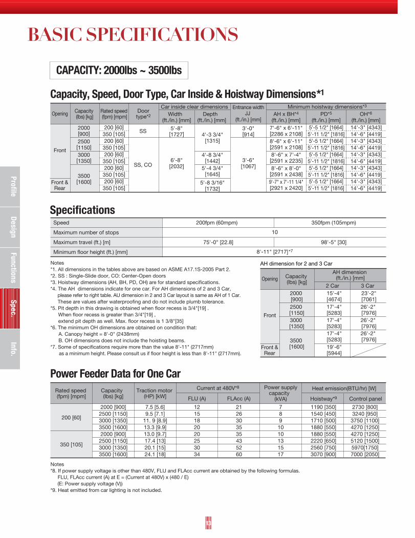
Notes*1. All dimensions in the tables above are based on ASME A17.1S-2005 Part 2. *2. SS : Single-Slide door, CO: Center-Open doors*3. Hoistway dimensions (AH, BH, PD, OH) are for standard specifications. *4. The AH dimensions indicate for one car. For AH dimensions of 2 and 3 Car, please refer to right table. AU dimension in 2 and 3 Car layout is same as AH of 1 Car. These are values after waterproofing and do not include plumb tolerance.*5. Pit depth in this drawing is obtained when floor recess is 3/4"[19] . When floor recess is greater than 3/4"[19] , extend pit depth as well. Max. floor recess is 1 3/8"[35]*6. The minimum OH dimensions are obtained on condition that: A. Canopy height = 8'-0" (2438mm) B. OH dimensions does not include the hoisting beams. *7. Some of specifications require more than the value 8'-11" (2717mm) as a minimum height. Please consult us if floor height is less than 8'-11" (2717mm).
Notes*8. If power supply voltage is other than 480V, FLU and FLAcc current are obtained by the following formulas. FLU, FLAcc current (A) at E = (Current at 480V) x (480 / E) (E: Power supply voltage (V))*9. Heat emitted from car lighting is not included.
Speed
Maximum number of stops
Maximum travel (ft.) [m]
Minimum floor height (ft.) [mm]
200fpm (60mpm)
75'-0" [22.8]
350fpm (105mpm)
98'-5" [30]
Capacity, Speed, Door Type, Car Inside & Hoistway Dimensions*1
Specifications
SS
SS, CO
5'-5 1/2" [1664]5'-11 1/2" [1816]5'-5 1/2" [1664]5'-11 1/2" [1816]5'-5 1/2" [1664]5'-11 1/2" [1816]5'-5 1/2" [1664]5'-11 1/2" [1816]5'-5 1/2" [1664]5'-11 1/2" [1816]
Capacity (lbs) [kg]
200 [60]350 [105]200 [60]350 [105]200 [60]350 [105]200 [60]350 [105]200 [60]350 [105]
Rated speed (fpm) [mpm]
Doortype*2
Car inside clear dimensions Minimum hoistway dimensions*3
14'-3" [4343]14'-6" [4419]14'-3" [4343]14'-6" [4419]14'-3" [4343]14'-6" [4419]14'-3" [4343]14'-6" [4419]14'-3" [4343]14'-6" [4419]
6'-8"[2032]
5'-8"[1727]
Width (ft./in.) [mm]
Depth (ft./in.) [mm]
7'-6" x 6'-11"[2286 x 2108]8'-6" x 6'-11"[2591 x 2108]8'-6" x 7'-4"[2591 x 2235]8'-6" x 8'-0"[2591 x 2438]9'-7" x 7'-11 1/4"[2921 x 2420]
AH x BH*4
(ft./in.) [mm]PD*5
(ft./in.) [mm]OH*6
(ft./in.) [mm]
3'-6"[1067]
3'-0"[914]
Entrance widthJJ
(ft./in.) [mm]
4'-3 3/4"[1315]
4'-8 3/4"[1442]
5'-4 3/4"[1645]
5'-8 3/16"[1732]
2500[1150]
2000[900]
3000[1350]
3500[1600]
AH dimension for 2 and 3 Car
Capacity(lbs) [kg]
AH dimension(ft./in.) [mm]
2 Car 3 Car
2500[1150]
2000[900]
3000[1350]
3500[1600]
17'-4"[5283]
15'-4"[4674]
17'-4"[5283]17'-4"[5283]19'-6"[5944]
26'-2"[7976]
23'-2"[7061]
26'-2"[7976]26'-2"[7976]
Power Feeder Data for One CarRated speed(fpm) [mpm]
2000 [900]2500 [1150]3000 [1350]3500 [1600]2000 [900]2500 [1150]3000 [1350]3500 [1600]
Capacity (lbs) [kg]
7.5 [5.6]9.5 [7.1]
11. 9 [8.9]13.3 [9.9]13.0 [9.7]17.4 [13]20.1 [15]24.1 [18]
Traction motor(HP) [kW]
Current at 480V*8
1215182020253034
FLU (A) FLAcc (A) Hoistway*9 Control panel
2126303535435260
7891010131517
Power supplycapacity
(kVA)
2730 [800]3240 [950]3750 [1100]4270 [1250]4270 [1250]5120 [1500]5970[1750]7000 [2050]
1190 [350]1540 [450]1710 [500]1880 [550]1880 [550]2220 [650]2560 [750]3070 [900]
Heat emission(BTU/hr) [W]
200 [60]
350 [105]
10
8'-11" [2717]*7
Opening
Front
Front &Rear
Opening
Front
Front &Rear
CAPACITY: 2000lbs ~ 3500lbs

Prof
ileD
esig
nFu
nctio
nsSp
ec.
Info
.
ProfileD
esignFunctions
Spec.Info.
13 14 15
CONTROLPANEL
Disconnect switch(by others)
Max
imum
tra
vel:
Ref
er t
o p
age
16.
Hoistway Plan Hoistway Section
FOR 1 CAR
FOR 2 CAR
Front & Rear Opening
Shown for Single-Slide door
Access door width3'-0"[914]
[1524]5'-0"
AH
JJ
BH
Car
insi
de c
lear
(Dep
th)
Car inside clear (Width)
JJ
Shown for Center-Open doors
BH
Car
insi
de c
lear
(D
epth
)
Car inside clear (Width)
JJ
Car inside clear (Width)
Access door width3'-0"[914]
JJ
JJJJ
AH
4"[102]
AU
[1676]5'-6"
AU
REAR SIDE
FRONT SIDE
FRONT SIDE
REAR SIDE
Car hitch beam: Refer to page 19.
Cab
hei
ght
8'-0
" [2
438]
(STD
)
Pit
dep
th P
D
Min
imum
floo
r he
ight
8'-1
1" [2
717]
Ove
rhea
d O
H
Ent
ranc
e he
ight
HH
7'-0
" [2
134]
(S
TD)
Hoisting beams (by others)
FRO
NT
SID
E
RE
AR
SID
E
CONTROLPANEL
CO
NTR
OL
PAN
EL
Disconnect switch(by others)
Notes*1. All dimensions in the tables above are based on ASME A17.1S-2005 Part 2. *2. SS : Single-Slide door, CO: Center-Open doors*3. Hoistway dimensions (AH, BH, PD, OH) are for standard specifications. *4. The AH dimensions indicate for one car. For AH dimensions of 2 and 3 Car, please refer to right table. AU dimension in 2 and 3 Car layout is same as AH of 1 Car. These are values after waterproofing and do not include plumb tolerance.*5. Pit depth in this drawing is obtained when floor recess is 3/4"[19] . When floor recess is greater than 3/4"[19] , extend pit depth as well. Max. floor recess is 1 3/8"[35]*6. The minimum OH dimensions are obtained on condition that: A. Canopy height = 8'-0" (2438mm) B. OH dimensions does not include the hoisting beams. *7. Some of specifications require more than the value 8'-11" (2717mm) as a minimum height. Please consult us if floor height is less than 8'-11" (2717mm).
Notes*8. If power supply voltage is other than 480V, FLU and FLAcc current are obtained by the following formulas. FLU, FLAcc current (A) at E = (Current at 480V) x (480 / E) (E: Power supply voltage (V))*9. Heat emitted from car lighting is not included.
Speed
Maximum number of stops
Maximum travel (ft.) [m]
Minimum floor height (ft.) [mm]
200fpm (60mpm)
75'-0" [22.8]
350fpm (105mpm)
98'-5" [30]
Capacity, Speed, Door Type, Car Inside & Hoistway Dimensions*1
Specifications
SS
SS, CO
5'-5 1/2" [1664]5'-11 1/2" [1816]5'-5 1/2" [1664]5'-11 1/2" [1816]5'-5 1/2" [1664]5'-11 1/2" [1816]5'-5 1/2" [1664]5'-11 1/2" [1816]5'-5 1/2" [1664]5'-11 1/2" [1816]
Capacity (lbs) [kg]
200 [60]350 [105]200 [60]350 [105]200 [60]350 [105]200 [60]350 [105]200 [60]350 [105]
Rated speed (fpm) [mpm]
Doortype*2
Car inside clear dimensions Minimum hoistway dimensions*3
14'-3" [4343]14'-6" [4419]14'-3" [4343]14'-6" [4419]14'-3" [4343]14'-6" [4419]14'-3" [4343]14'-6" [4419]14'-3" [4343]14'-6" [4419]
6'-8"[2032]
5'-8"[1727]
Width (ft./in.) [mm]
Depth (ft./in.) [mm]
7'-6" x 6'-11"[2286 x 2108]8'-6" x 6'-11"[2591 x 2108]8'-6" x 7'-4"[2591 x 2235]8'-6" x 8'-0"[2591 x 2438]9'-7" x 7'-11 1/4"[2921 x 2420]
AH x BH*4
(ft./in.) [mm]PD*5
(ft./in.) [mm]OH*6
(ft./in.) [mm]
3'-6"[1067]
3'-0"[914]
Entrance widthJJ
(ft./in.) [mm]
4'-3 3/4"[1315]
4'-8 3/4"[1442]
5'-4 3/4"[1645]
5'-8 3/16"[1732]
2500[1150]
2000[900]
3000[1350]
3500[1600]
AH dimension for 2 and 3 Car
Capacity(lbs) [kg]
AH dimension(ft./in.) [mm]
2 Car 3 Car
2500[1150]
2000[900]
3000[1350]
3500[1600]
17'-4"[5283]
15'-4"[4674]
17'-4"[5283]17'-4"[5283]19'-6"[5944]
26'-2"[7976]
23'-2"[7061]
26'-2"[7976]26'-2"[7976]
Power Feeder Data for One CarRated speed(fpm) [mpm]
2000 [900]2500 [1150]3000 [1350]3500 [1600]2000 [900]2500 [1150]3000 [1350]3500 [1600]
Capacity (lbs) [kg]
7.5 [5.6]9.5 [7.1]
11. 9 [8.9]13.3 [9.9]13.0 [9.7]17.4 [13]20.1 [15]24.1 [18]
Traction motor(HP) [kW]
Current at 480V*8
1215182020253034
FLU (A) FLAcc (A) Hoistway*9 Control panel
2126303535435260
7891010131517
Power supplycapacity
(kVA)
2730 [800]3240 [950]3750 [1100]4270 [1250]4270 [1250]5120 [1500]5970[1750]7000 [2050]
1190 [350]1540 [450]1710 [500]1880 [550]1880 [550]2220 [650]2560 [750]3070 [900]
Heat emission(BTU/hr) [W]
200 [60]
350 [105]
10
8'-11" [2717]*7
Opening
Front
Front &Rear
Opening
Front
Front &Rear
Hoistway Plan Hoistway Section
FOR 1 CAR
Shown for Single-Slide door
FOR 2 CAR
Shown for Center-Open doors
FOR 3 CAR
Shown for Center-Open doors
5'-0"[1524]
CONTROLPANEL
Disconnect switch(by others)
Access door width3'-0"[914]
AH
Car inside clear (Width)
Car
insi
de c
lear
(Dep
th)
BH
JJ
CONTROLPANEL
CO
NTR
OL
PAN
EL
Disconnect switch(by others)
Access door width3'-0"[914]
Car
insi
de c
lear
(Dep
th)
BH
Car inside clear (Width)
JJ
Car inside clear (Width)
JJ
5'-6"[1676]
4"[102]
AHAU AU
CO
NTR
OL
PAN
EL
CO
NTR
OL
PAN
EL
CO
NTR
OL
PAN
ELDisconnect switch
(by others)
Access door width3'-0"[914]
Car
insi
de c
lear
(Dep
th)
BH
Car inside clear (Width)
JJ
Car inside clear (Width)
JJ
Car inside clear (Width)
JJ
4"[102]
4"[102]
AHAU AU AU
7'-2"[2184]
Hoisting beams (by others)Car hitch beam: Refer to page 19.
Ove
rhea
d O
H
Ent
ranc
e he
ight
HH
7'-0
"[21
34] (
STD
)
Cab
hei
ght
8'-0
"[24
38] (
STD
)
Max
imum
tra
vel:
Ref
er t
o p
age
16.
Min
imum
floo
r he
ight
8'-1
1" [2
717]
Pit
dep
th P
D
Front OpeningCAPACITY: 2000lbs ~ 3500lbs

ProfileD
esignFunctions
Spec.Info.
Notes*1. All dimensions in the tables above are based on ASME A17.1S-2005 Part 2.*2. 2S : 2-Speed side-open doors*3. Hoistway dimensions (AH, BH, PD, OH) are for standard specifications.*4. The AH dimensions indicate for one car. For AH dimensions of 2 and 3 Car,
please refer to right table. AU dimension in 2 and 3 Car layout is same as AH of 1 Car.These are values after waterproofing and do not include plumb tolerance.
*5. Pit depth in this drawing is obtained when floor recess is 3/4"[19] .When floor recess is greater than 3/4"[19] ,extend pit depth as well. Max. floor recess is 1 3/8"[35]
*6. The minimum OH dimensions are obtained on condition that:A. Canopy height = 8'-0" (2438mm)B. OH dimensions does not include the hoisting beams.
*7. PD and OH dimensions should be increased when travel is over 98'-5" (30m).*8. Some of specifications require more than the value 8'-11" (2717mm)
as a minimum height. Please consult us if floor height is less than 8'-11" (2717mm).
Notes*8. If power supply voltage is other than 480V, FLU and FLAcc current are obtained by the following formulas.
FLU, FLAcc current (A) at E = (Current at 480V) x (480/ E) (E: Power supply voltage(V))
*9. Heat emitted from car lighting is not included.
Speed
Maximum number of stops
Maximum travel (ft.) [m]
Minimum floor height (ft.) [mm]
200fpm (60mpm) 350fpm (105mpm)
Capacity, Speed, Door Type, Car Inside & Hoistway Dimensions*1
Specifications
2S
5'-8" [1727]6'-1" [1854]5'-8" [1727]6'-1" [1854]
Capacity (lbs) [kg]
200 [60]350 [105]200 [60]350 [105]200 [60]350 [105]200 [60]350 [105]
Rated speed (fpm) [mpm]
Doortype*2
Car inside clear dimensions Minimum hoistway dimensions*3
15'-1" [4597]15'-2" [4623]15'-1" [4597]15'-2" [4623]15'-1" [4597]15'-2" [4623]15'-1" [4597]15'-2" [4623]
5'-10" [1778]
5'-8"[1727]
Width (ft./in.) [mm]
Depth (ft./in.) [mm]
8'-7 1/2” x 9'-1"[2629 x 2769]
8'-7 1/2” x 9'-8"[2629 x 2946]
8'-7 1/2” x 10'-3"[2629 x 3124]
8'-9 1/2” x 10'-3"[2680 x 3124]
AH x BH*4
(ft./in.) [mm]PD*5,*7
(ft./in.) [mm]OH*6,*7
(ft./in.) [mm]
4'-6" [1372]
4'-0" [1219]
Entrance widthJJ
(ft./in.) [mm]
7'-4 1/4" [2242]
7'-11 1/4" [2419]
8'-6 1/4" [2597]
4000[1800]
AH dimension for 2 and 3 Car
Capacity(lbs) [kg]
AH dimension(ft./in.) [mm]
2 Car 3 Car
4500 [2000]
4000 [1800]
5000 [2250] 17'-7 1/32"
[5462] 27'-0 9/16"
[8244]
Power Feeder Data for One CarRated speed(fpm) [mpm]
4000 [1800]4500 [2000]5000 [2250]4000 [1800]4500 [2000]5000 [2250]
Capacity (lbs) [kg]
16.1 [12] 17.4 [13] 18.8 [14] 26.8 [20] 29.5 [22] 33.5 [25]
Traction motor(HP) [kW]
Current at 480V*8
232628394348
FLU (A) FLAcc (A) Hoistway*9 Control panel
40 45 49 69 77 85
121314192224
Power supplycapacity
(kVA)
4780 [1400]5460 [1600]5970 [1750]8360 [2450]9220 [2700]
10240 [3000]
2390 [700]2730 [800]3070 [900]4100 [1200]4610 [1350]5120 [1500]
Heat emission(BTU/hr) [W]
200 [60]
350 [105]
24
195' [60]
8'-11" [2717]*8
16
Opening
Front
Opening
Front
CAPACITY: 4000lbs ~ 5000lbs
6'-1" [1854]
4500[2000]
5000[2250]
26'-6 17/32" [8091]
17'-7 1/32" [5360]

Prof
ileD
esig
nFu
nctio
nsSp
ec.
Info
.
17 18
Hoistway Plan
Front Opening
Shown for 2-Speed side-open doors
Shown for 2-Speed side-open doors
Max
imum
tra
vel:
Ref
er t
o p
age
16.
Car hitch beam: Refer to page 20.
Cab
hei
ght
8'-0
" [2
438]
(STD
)
Pit
dep
th P
D
Min
imum
floo
r he
ight
8'-1
1" [2
717]
Ove
rhea
d O
H
Ent
ranc
e he
ight
HH
7'-0
" [2
134]
(S
TD)
Hoisting beams (by others)
CONTROLPANEL
Disconnect switch(by others)
FOR 1 CAR
Access door width3'-0"[914]
[1524]5'-0"
AH
BH
Car
insi
de c
lear
(Dep
th)
Car inside clear (Width)
JJ
FOR 2 CAR
BH
Car
insi
de c
lear
(D
epth
)
Access door width3'-0"[914]
AH
4"[102]
AU
[1676]5'-6"
AU
CONTROLPANEL
CO
NTR
OL
PAN
EL
Disconnect switch(by others)
Car inside clear (Width) Car inside clear (Width)
JJ JJ
Hoistway Section

Prof
ileD
esig
nFu
nctio
nsSp
ec.
Info
.Profile
Design
FunctionsSpec.
Info.
19 20
For Concrete and Masonry Wall Construction
For Dry Wall Construction
Hoistway plan
Section A-A
Section A-A Section B-B Section C-C
Section B-B Section A-A Section B-B
Hoistway section
FRONT SIDE
REAR SIDE
C
(Min. 4 1/8" [105])
AHC
RA
RB
1" [2
5]H
HC
Car hitch beam
Through hole for car hitch beam
C(Min. 5 1/2" [140])
[300
]11
13/
16"11" [280]
Through holefor car hitch beamC (Min.4 1/8"[105])
Embedded steel plate8"X13"X3/8" [200X300X9.4](By other)
[300
]11
13/
16"11" [280]
[300]11 13/16"
[200
]7
7/8
"
Car hitch beam
(By other)Support beam
(By other)Mounting plate
(By other)
Support beam
(By other)
Mounting plate2-19X52 Elongated holes
[165
]6
1/2
"
3 1
5/16
" [1
00]
[40]1 9/16"
Car hitch beam
(By other)Support beam
(By other)Mounting plate
To top floor
1 9/16"[40]
HH
C
Car hitch beam
(By other)
Embeddedsteel plate
To top floor
1" [2
5]
1 9/16" [40]
HH
C
To top floor
Car hitch beam
1" [25]
(By other)
Embedded steel plate
HH
C
C = 5 1/2"[140]> C < 5 1/2"[140]
A
A
B
B
B
C C
B
B
B
Reaction loads
RA(lbs) [kN]
RB(lbs) [kN]Capacity
(lbs) [kg]
2500[1150]
2000[900]
3000[1350]3500[1600]3500[1600]
Static
3900[17]
3200[14]
3900[17]
4300[19]
3900[17]
Dynamic
7500[33]
6300[28]
7700[34]
7700[34]
8400[37]
Static
1200[5]
900[4]
1200[5]
1200[5]
1500[7]
Dynamic
2100[9]
1800[8]
2100[9]
2300[10]
2800[13]
Height of through hole for car hitch beam [HHC]*1
Rated speed (fpm) [mpm] HHC (ft./in.) [mm]
350 [105]200 [60]
12'-1 1/8"[3686]11'-10 1/8"[3610]
Opening
Front
Front & rear
Reaction loads
*1: The HHC dimensions are obtained when canopy height = 8'-0" (2438mm).
RA(lbs) [kN]
RB(lbs) [kN]Capacity
(lbs) [kg]
4500[2000]
4000[1800]
5000[2250]
Static
4900[22]
4900[22]
5600[25]
Dynamic
9800[44]
9700[43]
11000[49]
Static
1400[7]
1400[7]
1700[8]
Dynamic
2700[12]
2800[13]
3300[15]
Height of through hole for car hitch beam [HHC]*1
Rated speed (fpm) [mpm] HHC (ft./in.) [mm]
200 [60]350 [105]
12'-5 7/8" [3807]12'-6 7/8" [3833]
Opening
Front
CAR HITCH BEAM
CAPACITY: 2000lbs ~ 3500lbs CAPACITY: 4000lbs ~ 5000lbs
Hoistway plan Hoistway section
C
(Min. 4 1/8" [105])
AHC
1" [2
5]H
HC
Car hitch beam
A
A
For Concrete and Masonry Wall Construction
For Dry Wall Construction
Section A-A
Section A-A Section B-B Section C-C
Section B-B Section A-A Section B-B
Through hole for car hitch beam
C(Min. 5 1/2" [140])
[300
]11
13/
16"11" [280]
Through holefor car hitch beamC (Min.4 1/8"[105])
Embedded steel plate8"X13"X3/8" [200X300X9.4](By other)
[300
]11
13/
16"11" [280]
[300]11 13/16"
[200
]7
7/8
"
Car hitch beam
(By other)Support beam
(By other)Mounting plate
(By other)
Support beam
(By other)
Mounting plate2-19X52 Elongated holes
[165
]6
1/2
"
3 1
5/16
" [1
00]
[40]1 9/16"
Car hitch beam
(By other)Support beam
(By other)Mounting plate
To top floor
1 9/16"[40]
HH
C
Car hitch beam
(By other)
Embeddedsteel plate
To top floor
1" [2
5]
1 9/16" [40]
HH
C
To top floor
Car hitch beam
1" [25]
(By other)
Embedded steel plate
HH
C
C = 5 1/2"[140]> C < 5 1/2"[140]
B
B
B
C C
B
B
B
RB
RA
*1: The HHC dimensions are obtained on condition that:A. Canopy height = 8'-0" (2438mm)B. Travel 98'-5" (30m)

Prof
ileD
esig
nFu
nctio
nsSp
ec.
Info
.Profile
Design
FunctionsSpec.
Info.
21 22
For Concrete and Masonry Wall Construction
Single-Slide door(section C-C)
Center-Open doors(section C-C)
2-Speed side-open doors(section C-C )
For Dry Wall Construction
Single-Slide door(section C-C)
Center-Open doors(section C-C)
2-Speed side-open doors(section C-C)
6
1/2
[16
5]
6
1/2
[16
5]

Prof
ileD
esig
nFu
nctio
nsSp
ec.
Info
.Profile
Design
FunctionsSpec.
Info.
Work Not Included in Elevator Contract
Elevator Site Requirements
• Maintain the temperature and environment of the elevator hoistway and controller room between 70 and 80 degrees (F).
• The following conditions are required for maintaining elevator performance:
a. The relative humidity shall be below 90% on a monthly average and below 95% on a daily average.
b.The elevator hoistway shall be finished with mortar or other materials so as to prevent concrete dust.
• Voltage fluctuation shall be within a range of +5% to -10%.
Ordering Information
Please include the following information when ordering or requesting estimates:
• The desired number of units, speed and loading capacity
• The number of stops or number of floors to be served
• The total elevator travel and each floor-to-floor height
• Operation system
• Selected design and size of car
• Entrance design
• Signal equipment
• A sketch of the part of the building where the elevators are to be installed
• The voltage, number of phases and frequency of the power source for the motor and lighting
The following items are excluded from Mitsubishi Electric's elevator installation work, and are therefore the responsibility of
the building owner or general contractor:
• Architectural finishing of the walls and floors in the vicinity of the entrance hall after installation has been completed.
• Code-compliant construction of a legal, ventilated and waterproof hoistway and controller room as required by engineering
criteria to be fumished later.
• A ladder to the elevator pit.
• Provision for cutting the necessary openings as required by elevator contractor.
•Rail and building supports as required by elevator contractor.
•All work normally related to building construction.
•All necessary electrical power required for elevator operation, delivered to elevator controller room and hoistway.
• The installation of conduit between the elevator pit and the terminating point for the emergency bell, intercom, fire-panel, etc.
•Temporary power for installation and final testing.
• Code-compliant barricades, work lighting and acceptable electrical power during installation and testing.
•The provision of a suitable, locked storage space for elevator equipment and tools during elevator installation.
* Work responsibilities during installation and construction shall be determined according to local codes and building practices.
Mitsubishi Electric Inazawa Works has acquired ISO 9001 certification by the International Standards Organization (ISO) based on a review of quality management for the System.The plant has also acquired the environmental management system standard ISO 14001 certification.Contact your Mitsubishi Electric representative for more information.
23 24