Design Basis for Offshore Wind Turbines for shallow and deep water
32
Design Basis for Offshore Wind Turbines for shallow and deep water Trial Lecture, PhD thesis defense, UiS, 21 st June, 2013 . Arunjyoti Sarkar PhD Student, UiS Advisors . Prof. Ove T. Gudmestad UiS Prof. Daniel Karunakaran UiS / Subsea 7
Transcript of Design Basis for Offshore Wind Turbines for shallow and deep water

Design Basis for Offshore Wind Turbines for shallow and deep water
Trial Lecture, PhD thesis defense, UiS, 21st June, 2013 .
Arunjyoti Sarkar PhD Student, UiS
Advisors
.
Prof. Ove T. Gudmestad UiS
Prof. Daniel Karunakaran UiS / Subsea 7

Design Basis for Offshore Wind Turbine for shallow and deep water
Sequence in this presentation
1. Background and introduction: what is an offshore wind turbine – shallow and deep water
2. Design basis: purpose of a design
3. Information to be included in a design basis
4. Summary
Slide 2

• We need green energy for the security of our future
• First offshore wind turbine was established in offshore Denmark in 1997
• EU’s 2020 target: to produce 40 GW renewable power from offshore wind
• Today, different offshore wind farms are located at sites with water depth <50m
• In 2010, 2.5% of the world’s electricity is produced from wind, and increasing by 25% per annum.
Background and introduction: wind energy - why offshore
Slide 3
• Wind speed is larger at offshore and less turbulence. Power ∝ (wind speed)3
• Offshore sites are beyond the visibility range from onshore
• Noise produced by the blades is not an issue: generator design constraints are relaxed
• Current research thrust is focused to optimize the designs for deeper waters.
Source:

• A generator whose power source is the flow of wind
• The generator is housed in Nacelle and placed at the top of a tower
• The blades are connected to the hub, which is connected with the shaft.
• Gear box may or may not be present
• Today, a typical offshore wind turbine unit can produce 5 MW power
• Turbines with higher capacities (> 5 MW) are in design / testing phase
Background and introduction: what is a wind turbine
Slide 4
• The generator and the tower are today supplied by turbine manufacturers, which are then placed over the support structure
• The structure can be divided into two parts, generator and the support structure (tower and foundation)

Typical components of a support structure are:
• Tower
• Transition piece
• Foundation
• Others (J tube, stair case, cables, cable supports, helideck)
Tower and transition piece are simple cylindrical members. Various types of foundations can be used based on the water depth.
Background and introduction: what are the various structural components
Slide 5

Project phases
• The work in different project phases need different levels of design basis
• The phases are:
– Planning
– Designing (to be improved from planning to designing)
– Fabrication
– Installation (structure and cables)
– Commissioning and grid connection
– Operation, Inspection and maintenance
– Decommissioning
• In case the design basis is not sufficiently accurate, huge aditional costs can incur
• This applies in particular to geotechnical information
• Selection of a vessel that cannot handle the waves, could cause very long delays
Slide 6

In any work, there are always more than one limiting factors. This requires that the working process must be designed such that it can face any challanges during the execution or during fulfilling the purpose of the work.
The design basis document ’’legally’’ specifies what the client wants and how the work is to be carried out.
It includes, in principle, all basic information needed by a contractor to carry out the job satisfactorily
Separate design basis documents are issued for various segments of the work:
Purpose of design_1
Slide 7
• Wind turbine (generator, blades)
• Applicable Standards
• Structural design
• Geotechnical investigation
• Fabrication of the structure
• Construction and installation
• Operation and inspection
• Intervention and maintenance
• Decommissioning
In this presentation, the discussion is oriented to the perspective of the structural designer.

A structural design basis includes all basic information needed by a contractor to carry out the job satisfactorily.
Structure: what type of structure (superstructure, foundation, geometry etc.)
Load cases and load combinations: Dead load, Live load, Operational load, Environmental load, Loads during temporary Phases, Accidental loads
Boundary condition: Geotechnical information
Material and its mechanical properties: to check the safety in the design
Standards and Recommended practices, e. g. safety level requirements: ensures safety in design
Any secondary structures and associated load cases
Optimization of the design
Purpose of design_2
Slide 8

A design basis for an offshore wind turbine should typically include (among others)
1. Applicable regulations, codes and standards, selection of safety level
2 Project description, main dimensions, location, water depths, bathymetry
3 Environmental description – metocean condition
4 Geotechnical information
5 Loads on the structure
6 Material and design acssessment methods
7 Interfaces and strutcural joints
8 Corrosion protection and coating
9 Numerical modelling issues
10 Other important issues for considerations
11 In-service inspection philosophy to be adopted (not included)
…
Apart from design basis, a design brief document is prepared separately to specify the method used in the design work.
Normally, the client and the contractor meet to discuss and agree on the plan for the work.
A design basis should include the following (among others)
Slide 9

Some of the relevant documents are listed below
– DNV-OS-J101: Design of offshore wind turbine structures, september, 2011
– DNV-OS-J201: Offshore substations for wind farms
– IEC 61400-1: Wind turbines design requirements
– IEC 61400-3: Wind turbines design requirements for offshore wind turbines
– IEC 61400-22: Wind turbines conformity testing and certification
– IEC 61400-24: Wind turbines lightning protection
– GL renewable certifications (2005): Guideline for certifications of offshore wind turbines
– EN50308: Wind turbnines-protective measures-requirements for design operation and maintenance
– ABS guide for building and classing bottom founded offshore wind turbine installation
– BSEETA&R 650: Offshore wind turbine inspection refinements
– BSEETA&R 670: Design standards for offshore wind farms
– …
The support structures and foundation for offshore wind turbine will be designed for normal safety class (DNV-OS-J101), i.e., normal annual failure probility 10-4
1 Applicable regulations, codes and standards
Slide 10

2 Project description, main dimensions, location, water depth, bathymetry
Slide 11
• Location of the site
• Type of turbine
-Turbine capacity and range of operating rpm
-Nacelle mass including rotor (mass, MOIs)
-Rotor diameter
-Hub height from MSL
• Water depth (MSL)
-HAT
-LAT
-Storm surge
• Dominant wind speed and wave
• Platform level (the platform can be placed at the base of the tower or on the transition piece)
Currently, in offshore wind industry,
water depth ~ 25m is shallow water,
water depth ~ 50m is deep water Source: UpWind design basis

Wind
-Wind shear exponent for relevant roughness length
-Reference wind speed (typically at 10m)
-Annual mean wind speed at the hub
-Turbulance intensity
-Extreme wind speed (maximum wind speed with certain return period)
-Wind direction (wind rose diagram)
(Taken from UpWind design basis as example)
Slide 12
3 Environmental description – metocean condition_1

Seastate
-Water levels
-Current speed (direction, return period)
-Wave scatter diagram (operational wave), wave steepness and spectrum
-Swell (in combination with wind sea)
-Extreme wave (Hsmax and associated Tpeak)
-Wave heading direction (wave rose diagram)
-Breaking waves (slamming coefficient to be used) – depends on water depth
-Directional scatter of wind and wave, misalignment
Slide 13
3 Environmental description – metocean condition_2

Wave theory – shallow water
-Airy’s wave theory may not be sufficient in shallow waters
Slide 14
3 Environmental description – metocean condition_3
From: Hydrodynamics of offshore structures, Chakrabarti SK
-Large waves approaching from deeper water to shallower regions may undergoes deformation
-Breaking wave induced force can cause large acceleration at the nacelle and affect the normal operation of the generator
-Using a CFD model can provide accurate information on the force
From: Sung-Jin Choi, UiS
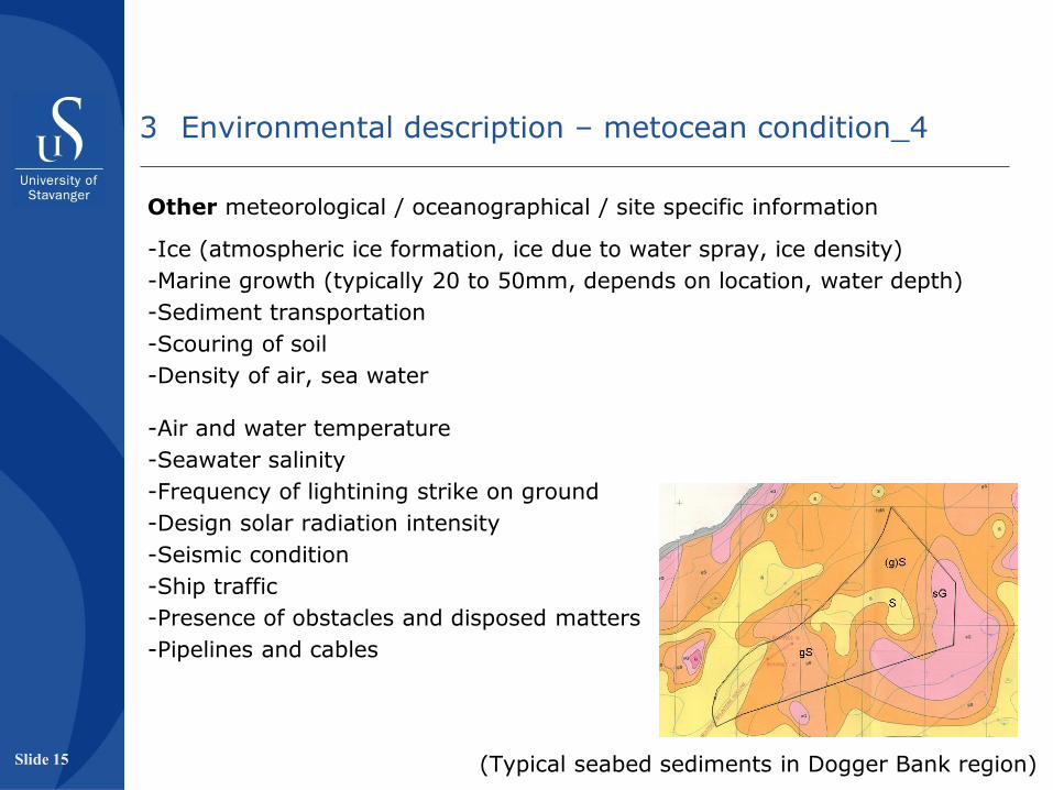
Other meteorological / oceanographical / site specific information
-Ice (atmospheric ice formation, ice due to water spray, ice density)
-Marine growth (typically 20 to 50mm, depends on location, water depth)
-Sediment transportation
-Scouring of soil
-Density of air, sea water
-Air and water temperature
-Seawater salinity
-Frequency of lightining strike on ground
-Design solar radiation intensity
-Seismic condition
-Ship traffic
-Presence of obstacles and disposed matters
-Pipelines and cables
Slide 15 (Typical seabed sediments in Dogger Bank region)
3 Environmental description – metocean condition_4

This is an important input to select the foundation type.
A thorough geotechnical investigation on the underlying layer is essential before using the seabed for load bearing (e.g., placing a heavy bottom supported installation vessel).
-Specifying various layers (of interest) below the seabed
-Identifying any local soft pocket in the soil
-Specific gravity
-Estimating the coefficient of internal friction / undrained shear strength values for each layer
-Dynamic soil spring stiffness
-Risk of soil liquilifation due to cyclic loadings
-Design basis for geotechnical investigation
Slide 16
4 Geotechnical information_1
Typical example

Geotechnical information for piles / monopiles
-Length of soil plug
-Axial and lateral bearing capacity curves
-Minimum wall thickness (mm)
-Drivability study of monopile (check the stress wave propagation)
-Driving fatigue study for monopile
-Settlement estimation
Note: Behavior of a monopile and typical small diameter offshore piles may be different, as the monopile is much stiffer. This is an active research area.
For other types of foundation design, existing design standards to be followed.
Scour protection arrangement to be specified based on the site condition.
For tripod type foundation, the behavior of soil scour is different.
Allowable scour depth to be specified in order to estimate the long term effect on the foundation stiffness.
Slide 17
10035.6
Dt
4 Geotechnical information_2

• All dead loads and live loads
• Generator load and blades
• Environmental load
• Other loads (boat landing, helideck)
Slide 18
Major difference between an OWT and a typical shallow water oil platform is the relatively large dynamic lateral load.
This requires to keep the fundamental natural frequency away from the excitation frequencies. Source: Presentation by Prof. Byme, University of Oxford
P = operating frequency of the generator
Load due to the blade passing frequency originates as the blade(s) interacts with turbulence.
-10% variation of the blade passing frequency
-Consider variation of stiffness of foundation during the operating period
5 Loads on structure_1

• Self weights of various components
• Range of the operating frequency of the generator
• Extreme wind load and wave load
• Hydrodynamic coefficients (smooth / rough cylinder, Reynold’s number)
• Wave theories to be used
• Other loads (boat landing, corrosion protection devices, J-tube, ladders) to be estimated by existing standards
• Fatige load in the structure to be set up from the scatter diagram
• Ice load (e.g., Baltic Sea)
Generator load cases can be considered following IEC. Some of the typically governing load cases are:
• Power production
• Power production in 50 yrs seastate
• Safety system fault
• Generator cut-out
• Idling in storm
• Idling after fault
These loads to be provided by the turbine manufacturer. Slide 19
5 Loads on structure_2

Other loads on the structure:
• Load in structural components during lifting and transportation
• Load in structural components during installation
• Ship impact load, helicopter load, boat landing load
• Load on access platforms
• Load on intermediate rest platform
• Load from hand rails, lower gangway
• Reaction loads from crane(s)
• Vertical slamming load on various parts where water surface interaction probability exists.
Load combination cases to be formulated with prescribed load factors
following applicable recommended practices
Slide 20
5 Loads on structure_3

Material:
• Mechanical properties of materials to be used
• Typically concrete is used for gravity foundation, steel is used for all other types.
• EuroCode 2 can be referred for detailed specifications on factor of safety and other related issues on concrete or RCC.
• For steel, relevant DNV or API recommended practices can be used.
(variation of yield stress / young’s modulus with steel grade, thickness, temperature)
• Quality of grout, see next slide
Acceptance criteria:
• For nacelle and rotor simultaneous installation
A general limitation for turbine components during transportation is 0.5g.
Various manufacturer specifies a limit during installation as 0.2g-0.5g.
• Allowable settlement / inclination
• Recommended practices to be followed to satisfy the ULS, FLS, SLS and ALS requirements.
Slide 21
6 Material and design assessment method

Structural joints between foundation and transition piece:
• Grout connection
• Bolted connection (should be pre-tensioned, as slip bolts have less fatigue life)
• Welded connection
The existing recommended practice to be used for all connections. Note that after several grout connection failure, new research studies (DNV) has been undertaken.
Slide 22
7 Interfaces and structural joints_1

Structural joints - Grout connection
The grout mixes should be tested for the following,
• Density
• Air content
• Workability
• Viscosity
• Stability (separatioon and bleeding)
• Setting time
• Compressive strength
• Shrinkage / expansion
• Effect of admixtures and compatibility
Considering installation loads, compressive strength of grout should be verified for an age less than 28 days
Sufficient number of tests must be carried out to perform a statistical evaluation of the results and establish the design values.
Slide 23
7 Interfaces and structural joints_2

Corrosion protection:
• Corrosion in air may be important
• Corrosion from the splash zone below must be taken into account
• Rate of corrosion 0.3mm/year (DNV)
• Legs are all flooded. Hence, both internal and external corrosion to be considered.
• For fully submerged members, cathodic protection can be used
• For fatigue calculation, half corrosion allowance to be used; for extreme case, full corrosion allowance to be used.
• Painting specification applies for the accessible portions of the structure
Slide 24
8 Corrosion protection and coating_1

Coating:
-Design life should be as far as possible corresponding to the life of the wind turbine
-Monitoring of the coating process
-Inspection and maintenance
Based on existing systems, recommended by DNV
-Atmospheric zone: ISO 12944-5, C5-M, system S7.09 or S7.14
-Splash zone: Glass flake reinforced epoxy (min. 1.5mm DFT)
Glass flake reinforced polyester (min. 1.5mm DFT)
Thermally sprayed Al with Si sealer (min. 200μ DFT)
-Submerged: Multilayer two components high build epoxy (min. 450μ DFT)
Cathodic protection
Details can be found in NORSOK M 501, DNV-OS-J101, DNV-OS-C401, ISO12499-7
Note: OWT structures For some OWT strutctures, coating damage reported after few years and corrosion started
Slide 25
8 Corrosion protection and coating_2

Analysis and software to be used for the design:
• OWT problem is typically defined as aero-hydro-servo-structural problem
• Fully coupled solution with CFD and FEM is costly, BEM model (or other) provides simpler approach
• For large number of sensitivity studies, decoupled analysis is more attractive
• HAWC2 / FAST / RIFLEX etc. (prefer those which provide ’’easy’’ dll links)
Recommended damping ratio:
• Important to be used in the dynamic analysis
Structural damping
Geotechnical damping 1%
Hydrodynamic damping
Aerodynamic damping 10-20% (log decreement)
• Run free vibration simulation(s) to estimate the damping incorporated in the numerical model
• Any change in stiffness and damping with time (sensitivity study)
Slide 26
9 Modelling features

Fatigue issue between monopile (shallow) and jacket (deep water ):
Jacket legs and braces are designed by ULS in splash zone, Monopile design is mainly determined by FLS
Free corrosion merely lead to reduction of active area for stress calculation: limited influence (typically heat affected zone, e.g., monopile’s connection with J-tube, boat landing, ladders etc.)
For FLS governed design, free corrosion shifts the S-N curve: significant influence (shift of curve may reduce fatigue life by a factor of 4)
If repaired, all corrosion must be removed
Some facts on monopile sizes
Slide 27
10 Other important issues for considerations_1
Traditional design of monopile appears arriving to its limit
Thinkness > 100mm, difficult to weld
Diameter > 6.0m, only few hammers can drive
Weight > 900 Te, only few vessel can handle
Source: Presentation LIC Engineering

Slide 28
For deeper water (~50m), optimization of the foundation is critical
Natural frequency requirement causes either large diameter monopile or expensive jackets
Alternative methods for optimization (using passive damper etc.) should be investigated
Ref. Mechanical Vibrations, Den Hartog
A possible direction for optimization in future:
10 Other important issues for considerations_2
Source: Vries W, Tempel J. Quick monopile design European offshore wind, Berlin, 2007.

Slide 29
Structures at further deeper water:
• Gravity based foundations / monopiles are suitable for ≤ 25m water depth
• Monopile / Jacket type foundations are suitable for ≤ 50m
• OWT on floaters appears suitable for ≥ 100m (active research area)
Currently, there are no suitable foundation solutions suggested for water depth around 50 to 100m. Design basis should encourage contractors in research.
Design basis for floating OWT shall include all the above mentioned aspects. Apart from these, two obvious points to be included are:
-Mooring lines / tethers (against translational or rotational motions of floater)
-Anchoring with the seabed (e.g., suction anchors)
Available recomended practices for TLPs, SPURs or Semisubmersible shall be followed.
10 Other important issues for considerations_3

The design basis serves as (i) a technical basis for design and construction of an offshore wind farm, (ii) a basis for managing project variation orders (together with contract)
Site specific data
Interface between wind turbine and support structure
Design standards
Design analysis and conditions
Manufacturing
Installation
Commissing
Operation and maintenance
Special focus to be added on integrated load model and flexibility of support structure for load calculation.
Problem areas like splash zone coating, wave slamming loads should be highlighted and guidance should be provided.
Summary
Slide 30

Slide 31
References
Petersen P, Neilsen KB, Feld T. Design basis for offshore wind turbine, Copenhagen Offshore Wind 2005.
DNV-OS-J101, Design of offshore wind turbine structures, 2011.
Seidel M. Design of support structures for offshore wind turbines – interfaces between project owner, turbine manufacturer, authoroties and designer, Stahlbau 79 (2010), vol. 9.
Fischer T, Vries WD, Schmidt B. UpWind design basis WP4 offshore foundations and support structures, Project UpWind.
OWA offshore wind farm UK round 3, Design basis version 2 (draft), Carbon Trust, 2009.
Siedel M, Mutius M, Steudel D. Design and load calculation for offshore wind foundations of a 5MW turbine, in: proceedings of DEWEK 2004.
Bulow L, Ljjj J, Gravesen H. Kriegers Flak offshore wind farm design basis for foundation, Vattenfall Vindkraft AB, 2008.