Combined Excitation Emission Spectroscopy of Europium ions ...

DESIGN AND SYNTHESIS OF NEW MULTIFUNCTIONAL
EUROPIUM MOLECULAR COMPLEX FOR OLEDS
A Report Submitted
for
Partial fulfilment Master of Science Degree
Under the Guidance of
Dr. Vaidyanathan Sivakumar
Submitted by
Ajit Kumar Pallei
Roll No. 412CY2018
DEPARTMENT OF CHEMISTRY
NATIONAL INSTITUTE OF TECHNOLOGY
ROUKELA, ODISHA - 769008
MAY 2014
ii
DECLARATION
I hereby declare that the project work entitled, “DESIGN AND SYNTHESIS OF NEW
MULTIFUNCTIONAL EUROPIUM MOLECULAR COMPLEX FOR OLEDS”
submitted to NIT Rourkela, is an original work done under guidance of Dr. Vaidyanathan
Sivakumar, Assistant Professor, Department of Chemistry, NIT Rourkela, and this project
work is submitted in the partial fulfilment of the requirements for the award of Master of
Science degree in Chemistry. The results incarnated in this thesis have not been
submitted to any other institute for any other degree.
Date: 06/05/2014 (Ajit Kumar Pallei)
412CY2018
NIT Rourkela

iii
Department of Chemistry
National Institute of Technology, Rourkela
THESIS CERTIFICATE
This is to certify that the thesis entitled “DESIGN AND SYNTHESIS OF NEW
MULTIFUNCTIONAL EUROPIUM MOLECULAR COMPLEX FOR OLEDS”
submitted by Mr. Ajit Kumar Pallei to the National Institute of Technology, Rourkela for
the award of degree of Master of Science is a bonafide record of research work carried out by
her under my supervision. The contents of this thesis, in full or in parts, have not been
submitted to any other Institute or University for the award of any degree or diploma.
Rourkela 769 008 Research Guide
Date: 06/05/2014
Dr. V. SIVAKUMAR

iv
ACKNOWLEDGEMENTS
I take this opportunity to express my profound gratitude and deep regards to my guide
Dr. Vaidyanathan Sivakumar for his exemplary guidance, monitoring and constant
encouragement throughout the course of this thesis. The blessing, help and guidance
given by him time to time shall carry me a long way in the journey of life on which I am
about to embark.
I would like to thank Dr. Niranjan Panda, Head, Department of Chemistry, and all the
faculty members of Department of Chemistry for their constant support and
encouragement in each and every step during my project.
My thanks and appreciations also go to Mr Rajamouli Boddula who helped me in
developing the project and implementing the experiments during my course work and my
lab mates Mr. Aravind, Mis. Kasturi, Mr. Jairam, Mr. Suraj Kumar and other
research scholars at Department of Chemistry, who have willingly helped me out with
their abilities.
Lastly, I thank almighty, my parents, family and friends for their constant encouragement
without which this assignment would not be possible.
(Ajit Kumar Pallei)

v
TABLE OF CONTENTS
SL. No. Contents Page No.
Acknowledgement …………………………………………………………… iv
Abstract ……………………………………………………………………… vii
1 Introduction ………………………………………………………. 1
1.1 Incandescence……………………………………………………. 1
1.2 Luminescence ……………………………………………………. 1
1.3 Triboluminescence ……………………………………………….. 2
1.4 Chemiluminescence …..…………………………………………. 2
1.5 Bioluminescence…. ……………………………………………... 2
1.6 Electroluminescence ……….…………………………………… 2
1.7 Fluorescence ……………………………………………………. 3
1.8 Phosphorescence ………………………………………………… 4
2 Lanthanides ……………………………………………………... 4
2.1 Classic DiekeDiagram for Lanthanide ions ………………………. 5
3. Organic light-emitting diode (OLED)…………………………….. 6
3.1 History of OLEDs ………………………………………………... 7
3.2. Types of OLEDs ………………………………………………….. 7
3.3 Architecture of OLEDs ………………………………………… 8
3.4 Advantages and Applications OLEDs…………………………….. 8
4. Bipolar ligand……………………………………………………... 9
5. Objectives of the work …………………………………………. 10
6. Experimental section………………………………………….... 11
6.1 General Information for synthesis………………………………… 11
6.2 Measurements……………………………………………………... 11
6.3 Experimental procedure ………………………………………… 11
6.4 Experimental Procedure …………………………………………. 13
7. Results and Discussion …………………………………………… 17
8. Summary and Conclusions ……………………………………….. 21
9. Scope for the future work ………………………………………… 21
10. References ……………………………………………………… 22
vi
LIST OF FIGURES
SL. No. Figure name Page No.
1. Types of light based on source……………………………………… 1
2. Jablonski diagram…………………………………………………… 3
3. Simplified mechanism for emission process………………………... 4
4. Classic Dieke diagram………………………………………………. 6
5 OLED device structure……………………………………………… 8
6. Normal energy level diagram of Eu(III) ion………………………… 9
7. Bipolar ligands………………………………………………………. 9
8. Scheme of synthesis for designed new efficient red emitter………... 12
9. Europium complex and Eu(TTA)3 under normal light and UV-light
(365nm)………………………………………………………………
18
10. The UV-visible absorption spectra of Europium complex and
Eu(TTA)3 in chloroform solution…………………………………
18
11. The photoluminescence emission spectra of Eu(TTA)3.2H2O,
Eu(TTA)3Phen-FL-TPA-DPA and Phen-Fl-TPA-DPA
19
12. Thermogravimetric analysis (TGA) for Phen-Fl-TPA-DPA and
Eu(TTA)3Phen-FL-TPA-DPA
20
LIST OF TABLES
SL. No. Name of table Page No.
1. Different types of luminescence………...…………………. 2
2. Types of OLEDs…………………………………………………… 7

vii
ABSTRACT
Key words: TPA-DPA, Fluorene, 1,10-Phenanthroline, π-π* transition
Lanthanide based OLEDs are gained much importance due to their line like emission
characteristics (f-f electronic transition) as well as phosphorescent visible range emission
(IQE up to 100%). Most of the hole transporting materials reported are derived from aromatic
amines, where the inclusion of arylamine units into the antenna should improve the hole
injection/transporting properties of the EuIII-phosphors. The present research work aim is to
increase the internal quantum efficiency by using chromophore (fluorene) molecule in order
to improve the π-π* transition in the antenna and facilitate the energy transfer to europium
ion, to link multi-functional ligands (TPA-DPA/ Fluorene and phenanthroline) that should be
active as well as capable of charge transport. To fulfil this, a new efficient red emitting
europium(III) molecular complex having neutral ligand [Eu(TTA)3 (Phen-Fl-TPA-DPA) -
Eu(TTA)3 = Tris (thenoyltrifluoroacetone) Europium (III), Phen-Fl-TPA-DPA = N1-(4-
(diphenylamino)phenyl)-N1-(4-(1-(9,9-diethyl-9H-fluoren-2-yl)-1H-imidazo[4,5-
f][1,10]phenanthrolin-2-yl)phenyl)-N4,N4-diphenylbenzene-1,4-diamine) has been designed.
The same has been successfully synthesised and optically characterised. The photophysical
studies of the synthesized Ligand (Phen-FL-TPA-DPA) and Eu-complex have been carried
out in the solution form by UV-Vis spectroscopy and spectrofluorimetry. The
photoluminescence emission spectra of Eu(TTA)3Phen-FL-TPA-DPA exhibits 5D0-7FJ (J=0-
4) transitions of Eu(III) ion. The characteristic emission observed at 612 nm due to 5D0-7F2
electric-dipole transition (non-centrosymmetric site). The thermogravimetric analysis (TGA)
shows that the compound is thermally stable (278oC (10%)) and it is good enough to fabricate
the OLED device using the synthesised Eu(III)-complex.
.
1. Introduction:
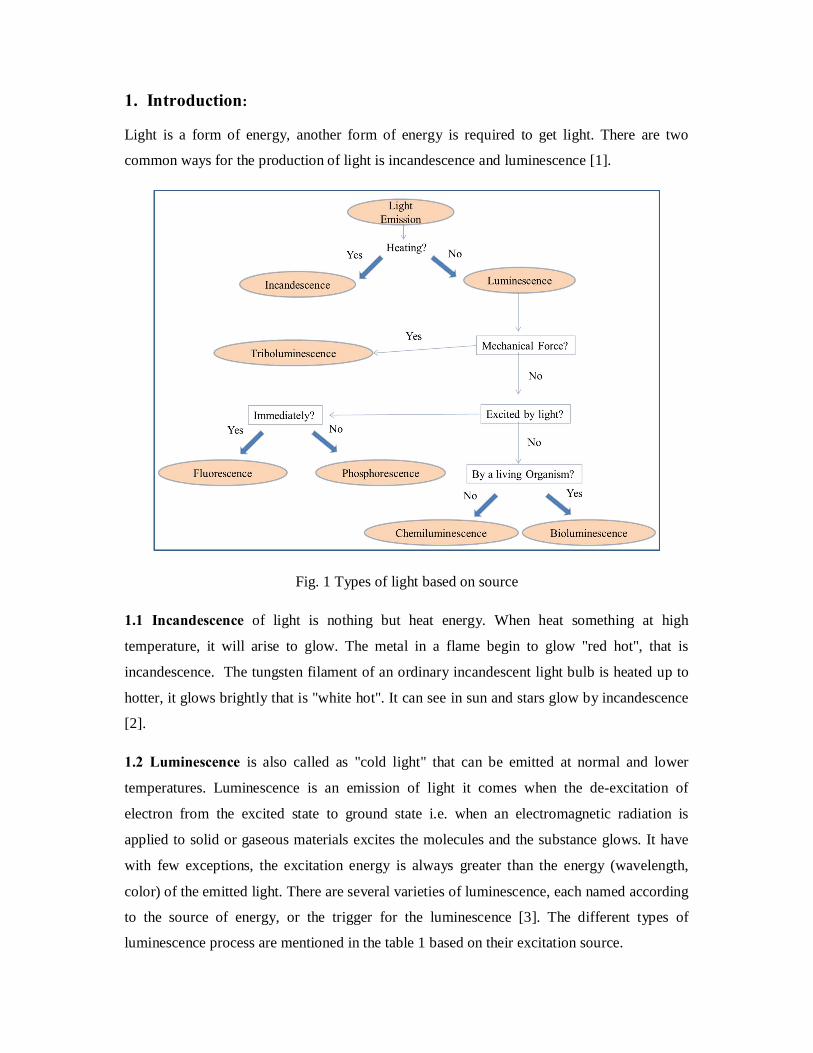
Light is a form of energy, another form of energy is required to get light. There are two
common ways for the production of light is incandescence and luminescence [1].
Fig. 1 Types of light based on source
1.1 Incandescence of light is nothing but heat energy. When heat something at high
temperature, it will arise to glow. The metal in a flame begin to glow "red hot", that is
incandescence. The tungsten filament of an ordinary incandescent light bulb is heated up to
hotter, it glows brightly that is "white hot". It can see in sun and stars glow by incandescence
[2].
1.2 Luminescence is also called as "cold light" that can be emitted at normal and lower
temperatures. Luminescence is an emission of light it comes when the de-excitation of
electron from the excited state to ground state i.e. when an electromagnetic radiation is
applied to solid or gaseous materials excites the molecules and the substance glows. It have
with few exceptions, the excitation energy is always greater than the energy (wavelength,
color) of the emitted light. There are several varieties of luminescence, each named according
to the source of energy, or the trigger for the luminescence [3]. The different types of
luminescence process are mentioned in the table 1 based on their excitation source.

2
Table 1. Different types of luminescence
Type Excitation Source Example
Bioluminescence Bio-chemical energy firefly, Photinus pyralis
Cathodoluminescence Cathode rays ( high energy
electrons )
microscopea
Chemiluminescence Chemical reaction energy luminol + hydrogen peroxide
→ 3-aminophthalate+ light
Electroluminescence Applied voltage OLEDs
Photoluminescence Photons ( UV, Visible )
Radioluminescence X-rays, γ rays, etc Radium salt
Sonoluminescence Sound waves Bubbles in liquid
Thermoluminescence Thermal stimulation of emission
which is excited by some other
means.
Sediment grains
Triboluminescence Mechanical energy such as
grinding, stress, etc.
Diamond
1.3 Triboluminescence is phosphorescence that is generated by mechanical action. This can
observed when the breaking of chemical bands in a material.
1.4 Chemiluminescence is light, as a result of chemical reaction. Examples of
chemiluminescencea are glow-in-the-dark plastic tubes sold in amusement parks.
1.5 Bioluminescence is luminescence caused by chemical reactions in living things; it is a
form of chemiluminescence. Fireflies glow by bioluminescence.
1.6 Electroluminescence is luminescence caused by electric current [4].
The photophysical process of the molecule is explained in the Jablonsky diagram (Fig. 2)

3
Fig. 2 Jablonski diagram
1.7 Fluorescence is the luminescence phenomena that occurred by supplying the energy in
the form electromagnetic radiation, usually ultraviolet light. The energy source excites an
electron of an atom from a lower energy level to an "excited" higher energy level and the
same falls back to a lower energy level by emitting photon (i.e) what is known as
fluorescence (s1 to s0) and it is allowed transition. The lifetime of an excited singlet state is
approximately 10-9 to 10-6 sec. Examples: fluorescent lights, the red glow of rubies in sunlight
[5].
1.7.1 Internal conversion is defined as radiationless processes where molecules in an excited
singlet state return to the ground state without the emission of a photon, converting all the
excitation energy into heat. The process called internal conversion. The life time of internal
conversion is 10-14 to 10-10. An example of this process is the quinine sulfate fluorescence, it
quenched by the use of various halide salts. In this case the excited molecule can de-excite by
increasing the thermal energy of the surrounding solvated ions.
1.7.2 Intersystem crossing is an isoenergetic radiationless transition between two electronic
states having a different multiplicity that is singlet (S) to triplet (T). It can occur within the
lifetime of an excited singlet state (10-10 to10-8 sec). It is facilitated by heavy metal ion (Ln
metal ion).

4
1.8 Phosphorescence is defined as when a molecule is placed in a rigid medium where
collisional processes are minimized, a radiative transition between the lowest triplet state and
the ground state is observed. This emission is called phosphorescence (T1 to S0). The decay
time of phosphorescence approximately equal to the lifetime of the triplet state (10-4 to 10
sec) as it originates from the lowest triplet state [6].
2. Lanthanides: In the recent years development of lanthanide based luminescent materials are playing an
important role due to f-f transitions. The excited states cannot be directly populated
efficiently because of their forbidden nature transition. To improve their emission intensity
requires a sensitizer that can populate the excited state manifold of the lanthanides by energy
transfer (ET). Efficient intersystem crossing is required (heavy metal ion effect or spin orbit
coupling). Mostly organic sensitizers have been used (due to their efficient absorption in the
UV region). Energy matching of the sensitizer states to those of lanthanides are of exited
states most importance [7] and the same in the pictorial view as shown in figure 3.
Fig. 3 Simplified mechanism for emission process
Lanthanides know as first inner transition series or third transition and come after lanthanum.
Lanthanides are classified as f block elements. Generally these are called as rare earths. These
are characterized by the filling up of the 4f energy levels which are not usually involved in
bonding. These highly electropositive elements have a common oxidation state of +3 and
generally resemble each other in their chemical and physical properties. They have a generic
symbol “Ln”. It contains 15 elements from lanthanum (La57) to lutetium (Lu71) [8]. In the
periodic table, covalent and ionic radii generally increase on descending a group due to the
presence of extra filled shells of electron. When we go from left to right across a period, the
covalent and ionic radii decrease. This is due to the extra orbital electrons incompletely shield

5
the extra nuclear charge. Thus the entire electrons are pulled in closer. The shielding effect of
electron decreases in the order s > p > d > f. the contraction in size from one element to
another is fairly small [9].
The photoluminescence properties of rare-earth (lanthanide) compounds have been attractive
for researchers from decades. Line-like emission of lanthanide is an attractive feature of
luminescent, which results in a high color purity of the emitted light. The emission color
depends on the lanthanide ion and it is also depend on layers (HT/ET material) of the device
which prefer to construct. Studies on these compounds have been limited to either inorganic
compounds (lanthanide phosphors) or molecular lanthanide compounds (for instance, the β-
diketonate complexes). The study of luminescent lanthanide compounds are used for different
a high potential applications (optical amplifiers, optical waveguides, OLEDs, etc.) [10].
Mostly the lanthanide materials are utilising for organic light emitting diodes (OLEDs) to
produce visible range light emission.
2.1 Classic DiekeDiagram for Lanthanide ions
The classic Dieke diagram of lanthanide ions is shown in Fig. 4.

6
Fig. 4 Classic Dieke diagram
3. Organic light-emitting diode (OLED):
Organic light-emitting diode is a display device that sandwiches carbon-based films between
two charged electrodes; those are cathode and anode respectively. The organic films consist
of a hole-injection layer, a hole-transport layer, an emissive layer and an electron-transport
layer. When the device is forward biased, electrons and holes moves from respective
electrodes, cathode and anode (ITO). The injected charges are recombined at emissive layer
to give emission in the form of light (EL). According to spin statistics the probability of
forming singlet states is 25% and the triplet states is 75%. The maximum fluorescent QE is
limited to 25% for the small organic molecule based OLEDs. To overcome the same
Baldoet.al., introduced phosphorescent materials (expected to harvest the triplet energy to the
ground state by light emission by spin orbit coupling, IQE can reach up to 100%) in the
OLEDs [11]. In the absence of Ln (III) ion complexes, only singlet excitons are proficient to

7
give light emission but not the triplet excitons. Ln based organic metallic complexes
incorporated in the emitting layer, both singlet and triplet excitons are utilized and which
leads to increase in the device efficiency. The heavy metal ion effect facilitates the energy
transfer from the singlet to triplet through ISC process and subsequently the emission arises
from the f level [12].
3.1 History of OLEDs:
In 1907, Captain Henry Joseph Round was demonstrated inorganic luminescence on a crystal
of carborandam [13]. Light emission from β-diketonates with lanthanide materials was first
reported by Weissmanin 1942 [14]. The EL from organic material such as acridine orange
has been observed first time by A Bernanose in 1955 [15]. In 1963 Pope reported single layer
organic EL device with anthracene crystals [16] after that the Helfrich and Schneider also
introduced single layer device [17]. In 1987, Tang and Vanshyke introduced high
performance two layer OLED by vacuum deposition of organic layers have low bias voltage
performance [18]. The dynamic work moved on OLEDs ofter this research work. In 1990,
Burrougheset al., observed electroluminescence from organic polymer [19].In organometallic
complex, ligand excitation energy is transferred to central metal ion through its triplet states
and produce emission. In general blue, green and red colors are essential for full colour
displays. Mixing of these colors produce the white color emission and it depends on host, HT,
ET materials along with their appropriate voltages [20].
3.2 There are mainly two types of OLEDS are available. Those are
(1) Passive OLEDs (2) Active OLEDs
Table 2. Types of OLEDs
Passive OLEDs Active OLEDs
Ø The organic layer is between strips of
cathode and anode that run perpendicular
Ø The intersections form the pixels
Ø Easy to make
Ø Use more power
Ø Best for small screens
Ø Full layers of cathode and anode
Ø Anode over lays a thin film transistor
(TFT)
Ø Requires less power
Ø Higher refresh rates
Ø Suitable for large screens

8
3.3 Architecture of OLEDs:
Fig. 5 OLED device structure
Substrate: clear plastic, glass, foil used as substrate in OLED.
Anode is source of holes. When a current flows through the device the holes will move from
anode.
Organic emissive layer is made of organic material which is using in middle of the device.
Cathode is source for electrons. When a current flows through the device the electrons will
move from cathode [21].
3.4 Advantages and Applications of OLEDs:
OLEDs are gained much importance due to their advantages such as longer life time, faster
switching on smaller size, environment friendly, low cost, low drive voltages, colour purity
and flexibility nature. Recently attractive results are reported on phosphorescent based
Organic light emitting diodes (OLED) due to their internal quantum efficiency (up to 100%).
The Ln based organometallic complexes are used in different applications such as cathode
ray tubes, Computer Screens, Keyboards, Digital Camera, air craft and space shuttles,
television screens, fluoro immune assay, biomedicine and related technology, biophysical
applications like receptors and sensing reagents of chiral biological substrates and photonic
crystals, full colour flat panel displays [22-23].
Usually Eu(III) complexes exhibit red emission in the region around 614nm due to 5D0-7F2
electronic transition (hyper sensitive). In order to obtain efficient emission, suitable designed
molecules (multifunctional ligand) have to be chosen and the same have to be incorporated in
suitable devices. In addition, the appropriate host materials have to be choosen and doping
concentration need to be optimized. In the case of phosphorescent based OLEDs one can
expect that the internal quantum efficiency (IQE) reach up to 100% (according to spin
statistics). However, the external quantum efficiency (EQE) is not that satisfactory, efforts
have been made to improve the EQE, and the different device structures have been

9
introduced. Charge carrier transportation and efficient recombination of the charge are more
important for the device efficiency (EQE). Drift mobilities of charges (holes and electrons) in
the device are strongly electric field and temperature dependent [24]. Lanthanide metal ions
almost exhibit sharp-emission bands because of the 4f shell shielded by their outer orbitals.
The Eu+3 metal ion shows 580, 592, 612, 652 and 703 nm emission lines corresponding f-f
transitions of 5D0-7F0, 5D0-7F1, 5D0-7F2, 5D0-7F3 and 5D0-7F4 (Fig. 6) [25].
Fig. 6 Energy level diagram of Eu(III) ion
4. Bipolar ligands:
The ligand which is having both donor and accepter capacity is known as bipolar ligand.
N
O
NN
Na
N-phenyl-N-(4-(5-(pyridin-4-yl)-1,3,4-
oxadiazol-2-yl)phenyl)benzenamine
N
N
N N
N
b
N-(4-(1-ethyl-1H-imidazo[4,5-
f][1,10]phenanthrolin-2-yl)phenyl)-N-
phenylbenzenamine
Fig. 7 Bipolar ligands a and b

10
The tittle compound, C25H18N4O (a), is a non-planar bipolar ligand containing triphenylamine
and 1,3,4-oxadiazole units. In the molecule, the benzene ring, the 1,3,4-oxadiazole ring, and
the pyridine ring are twisted slightly with respect to each other. It is well known that OLED
produces light via recombination of electrons and holes, which are injected from electrodes
on opposite sides of the device. Furthermore, the balance between the injection and
transportation of electron and hole carriers leads to a high luminescence efficiency. Because
triphenylamine and the 1,3,4-oxadiazol group possess good properties of hole transportation
and electron deficiency, respectively, the compound containing these two groups should be of
an increased electron affinity and transporting properties, resulting in a more balanced charge
recombination in the emissive layer [26]. Tris(dibenzoylmethanato)(2-4’-
triphenylamino)imidazo[4,5-f]1,10 phenanthroline) is the light-emitting center, hole-
transporting triphenylamine and electron-transporting phenanthroline fragments are
integrated into one molecule [27].
Based on the extensive literature study, in the present investigation a bipolar ligand has been
designed [multi functional ligand which is consist of phenanthroline, fluorene moiety and
triphenylamine-diphenylamine] and the same is utilized as a bipolar ligand for the Eu
molecular complex. The same is synthesized by the condensation of 1,10-phenanthroline-
5,6-dione, 4-(bis(4-(diphenylamino)phenyl)amino)benzaldehyde (TPA-DPA) and 9,9-
diethyl-9H-fluoren-2-amine.
5. Objectives of the work:
Although up to a great progress has been achieved in the development of green-emitters, full-
color-displays also require red and blue-emitters. In accordance with the energy-gap law, the
design and synthesis of efficient red emitters is intrinsically more difficult. Efforts have been
made to design and synthesis europium based molecular complexes as a red emitting
phosphor for OLEDs. From the literature survey we found these below tasks
(a) Design and synthesis of Eu based Lanthanide-luminophores (bright- monochromatic)
(b) Link the multifunctional ligands (Phen, Fl, TPA-DPA)
(c) Incorporate light-emitting luminophore (fluorene/β-diketone) in the antenna
(d) Fabricate Lanthanide-phosphors based OLEDs
(e) Improve the External Quantum efficiency (Above 5%)

11
6. Experimental Section:
6.1 General Information for synthesis:
All reactions were performed under inert (nitrogen) atmosphere. Solvents were carefully
dried and distilled from appropriate drying agents prior to use. Commercially (sigma Aldrich)
available reagents are used without further purification unless otherwise stated. All the
reactions was monitored by thin-layer chromatography (TLC) with silicagel 60 F254
Aluminium plates (Merk). Column chromatography was carried out using silica gel from
Aldrich (70 – 230 mesh, 60 Å).
6.2 Measurements:
1H-NMR and 13C-NMR spectra were recorded using a AV 400 Avance-III 400MHz FT-NMR
Spectrometer Bruker Biospin International, Switzerland, in deuterated chloroform and
deuterated dimethyl sulphoxide solution. Chemical shifts were quoted relative to
tetramethylsilane (TMS). Elemental analysis was measured by Elementar Analysen Systeme,
Germany/Vario EL. Mass spectra were recorded on an Perkin Elmer, USA/ Flexer SQ 300
M. The absorption spectrum was measured by using UV-visible spectrometer (Shimadzu
Corporation, Japan/UV-2450 Perkin Elmer, USA/Lamda 25). Thermo gravimetry analysis
were measured by DTA-Thermo Gravimetric Analyser (Shimadzu / DTG-60H).
6.3 Scheme of synthesis:
O2N
H2N
Br HNO3
1 1-1 1-2
1-3
NH2NH2.H2O
Pd/C, Ethanol, Reflux, 10h, 90%
KOH, KI, DMSO, OoC 12h, 71%
ACOOH, 70oC, 24h, 91%9H-fluorene 9,9-diethyl-9H
-fluorene9,9-diethyl-2-nitro
-9H-fluorene
9,9-diethyl-9H-fluoren-2-amine

12
N
CHO
N
CHO
II
N
CHO
NN
N DMF, POCl3 KI, KIO4
ACOOH
DPA
Dichloro benzene
4 4-1 4-24-3
TPA-DPA
N N
O O
H2N NH4OAc
Glacial AcOH, Reflux
N N
NNN
CHO
NNN
NN
Phen-Fl-TPA-DPA
2-1 1-3
4-3
TPA-DPA
O
OEu
Cl
6H2O
Cl
Cl
3
NaOH, Ethanol
H2O,RT, 60oC O
O
Eu
OH2
OH2
Eu (TTA) 3 .2H2OTris (thenoyltrifluoroacetone) Europium (III) hydrate
TTA
Phen-Fl-TPA-DPA
THFNN
N N
N
3O O
Eu
F
F
N N
FF
S
S
S
FF
F
FF
Thenoyltrifluoroacetone
Europium chloride hexahydrate
Eu(TTA)3 Phen-Fl-TPA-DPA
Fig. 8 Scheme of synthesis for designed new efficient red emitter [28-30]

13
6.4 Experimental Procedure:
1) Synthesis of 9,9-diethyl-9H-fluorene (1-1):
The powdered potassium hydroxide (KOH) (1.4g, 25.30mmol, 4.2eq) was added to a solution
of Fluorene (1g, 6.024mmol, 1eq) in DMSO (25mL) and added 1-bromo ethane (0.97mL,
13.25mmol, 2.2eq) and KI (0.09g, 0.602mmol, 0.1eq) at OoC. The reaction mixture (RM)
was stirred for 12hrs at room temperature and the progress of the reaction was monitored by
TLC (1:9 EtoAc: Hexane, Rf is 0.75). RM was pour into ice-cold water then extracted with
chloroform (3×30mL). The combined organic layer was washed with brine and diluted
hydrochloric acid (HCL) solution followed by drying with sodium sulphate, solvent
evaporated to get 1.1g crude product with mixture of compounds. Purification carried out by
using silica gel (100-200 mesh, EtoAc: Hexane 2:98) to a yield 1-1 a whitish color solid with
950mg (71%).
1H-NMR Data (CdCl3, 400MHz): δ 7.75-7.73 (m, 2H), 7.42-7.37 (m, 2H), 7.37-7.34 (m, 2H),
7.38-7.27 (m, 2H), 2.05 (q, 4H) and 0.34 (t, 6H).
2) Synthesis of 9,9-diethyl-2-nitro-9H-fluorene (1-2):
Into a clean two neck round bottom flask pour 1-1(0.2g, 0.899mmol) and added acetic acid
(1.6mL) solution at RT. This mixture was heated to 50oC then added nitric acid (0.2g,
5.411mmol) drop wise. The resulting mixture was stirred for 24hrs at 70oC and the progress
of the reaction was monitored by TLC (1:9 EtoAc: Hexane, Rf is 0.5). RM was cool to RT
and poured into water then basified with diluted sodium hydroxide solution up to pH 6
(neutral), extracted with ethyl acetate combined organic layer was washed with brine
followed by dried with anhydrous sodium sulphate, solvent was evaporated to get crude
compound. This was washed with hexane and diethyl ether simultaneously to get 1-2
(220mg, 91%) with brick yellow color solid.
1H-NMR Data (CdCl3, 400MHz): δ8.29-8.15 (m, 3H), 7.81-7.74 (m, 2H), 7.47-7.35 (m, 2H),
2.10-2.06 (m, 4H) and 0.38-0.33 (m, 6H).
3) Synthesis of 9,9-diethyl-9H-fluoren-2-amine (1-3):
To a stirred solution of 1-2 (200mg, 0.749mmol) in ethanol (15 mL) added hydrazine
monohydrate (0.5 mL) at RT. Then palladium on carbon (Pd/C, 10% w/w) (0.05g) was added
under nitrogen atmosphere and resulting mixture was reflux (85oC) for 10hrs. The progress of

14
the reaction was monitored by TLC (EtOAc: Hexane 2:8Rf is 0.6, ninhydrin active) and RM
was filtered through celite bed followed by concentrated to get 190mg of 1-3 crude
compound. This was purified with column chromatography by using silica gel (100-200
mash). The compound eluted with 8% ethyl acetate in pet ether and solvent concentrated to
get 160mg (90%) 1-3 pure compound.
1H-NMR Data (CdCl3, 400MHz): δ 7.58-7.56 (m, 1H), 7.51-7.49 (m, 1H), 7.30-7.28 (m, 1H),
7.26-7.20 (m, 2H), 6.69-6.67 (m, 2H), 3.65 (bs, 2H), 2.03-1.91 (m, 4H) and 0.34 (t, 6H).
4) Synthesis of 4-(diphenylamino)benzaldehyde (4-1) :
Dimethylformamide (DMF) (1.71mL, 22.04mmol) was taken in a clean-dried two neck round
bottom flask and added drop wise phosphorous oxy chloride (2.05ml, 22.04mmol) at 5oC.
After 30min, triphenylamine (TPA) (2g, 8.163mmol) in DMF (15mL) was added drop wise
to reaction mixture at same temperature. The RM was appears in brick yellow color and the
progress of the reaction was monitored by TLC (EtOAc in Hexane 1:9, Rf-0.4). The resulting
mixture was stirred for overnight at RT, then poured into water and neutralized with diluted
sodium hydroxide solution (up to pH 6). Then extracted with chloroform and washed with
brine solution followed by dried with sodium sulphate and removal of solvent to get 2.2g of
crude (4-1). The crude product was washed with diethyl ether: hexane (3:7) mixture solvent
and recrystallization in ethanol to get 2g pure 4-(diphenylamino)benzaldehyde(4-1) (90%)
with pale yellow colored fine solid.
1H-NMR Data (CdCl3, 400MHz): δ 9.82 (s, 1H), 7.70 (d, 2H), 7.38-7.34 (m, 2H), 7.25-7.24
(m, 2H), 7.20-7.15 (m, 6H), 7.03 (d, 2H).
13C-NMR Data (CdCl3, 100MHz): δ 153.3, 146.1, 131.3, 129.7, 129.0, 126.3, 125.1, 119.3.
EI-mass: m/z 274 (M++1)
5) Synthesis of 4-(bis(4-iodophenyl)amino)benzaldehyde (4-2):
Under rapid stirring, 4 (2.73 g, 10 mmol) was dissolved in glacial acetic acid (10 mL) and KI
(3.32 g, 20 mmol) and KIO3 (6.42 g, 30 mmol) were added; the reaction mixture was stirred
for 3 h at 700 C. After cooling, the solid was filtered off and washed thoroughly with water
(50 mL) and dichloromethane (100 mL). The aqueous phase was extracted several times with
dichloromethane. The combined organic phases were washed with a diluted ammonia
solution (10%) until pH becomes nearly 8, with a saturated NaHCO3 solution, and with

15
saturated brine and dried over MgSO4. After removal of the solvents, the crude compound
was stirred for 15 min in boiling ethanol (50 mL); the solution was cooled, and the pure
product was isolated by filtration (4.2 g, 80%). Yellow solid,
1H-NMR Data (DMSO, 400MHz): δ 9.859 (s, 1H), 7.72 (d, 2 H), 7.64 (d, 4H), 7.07 (d, 2H),
6.91 (d, 4H).
6) Synthesis of 4-(bis(4-(diphenylamino)phenyl)amino)benzaldehyde (4-3) (TPA-DPA):
In a 250mL round bottom flask, 4-[N,N-di(4-iodophenyl)amino]- benzaldehyde (1g,
1.9mmol), diphenylamine (0.98g, 5.7mmol), potassium carbonate (2.09g, 15.2 mmol) copper
iodide (0.28g, 1.52mmol) and 18 – crown – 6 (0.01g, 0.38mmol) were reflexed in 1,2 –
dichlorobenzene (15mL) for 48 hrs, under nitrogen atmosphere. The inorganic components
are filtered while hot and then the product was precipitated in methanol. The crude product
was purified by column chromatography on silica (petroleum ether: dichloromethane = 1:1,
v/v) to afford the product as yellow powder (yield: 59 %).
1H-NMR Data (DMSO, 400MHz): δ 9.815 (s, 1H), 7.22 (t, 9H), 7.05 (d, 9H), 6.96 (d, 3H),
6.81 (t, 4H).
13C NMR data (100MHz, DMSO-d6): δ 190.97, 141.45, 140.82, 140.56, 140.15, 132.10,
130.02, 129.80, 127.91, 125.16, 125.11, 123.75, 115.40.
FT-IR Data (KBr): γC-C = 1501(aromatic), γC-N = 1308 (aromatic), γC-H (S) = 695
7) Synthesis of N1-(4-(diphenylamino)phenyl)-N1-(4-(1-(9,9-diethyl-9H-fluoren-2-yl)-
1H-imidazo[4,5-f][1,10]phenanthrolin-2-yl)phenyl)-N4,N4-diphenylbenzene-1,4-
diamine (Phen-Fl-TPA-DPA):
1-3 (0.75g, 3.171mmol) was added to a stirred solution of 4-3 (1.75g, 2.883mmol) in glacial
acetic acid (30mL) at room temperature. To this reaction mixture subsequently ammonium
acetate (2.2g, 28.83mmol) and 2-1 (0.60g, 2.883mmol) was added. Then resulting mixture
was stirred for 12hrs at 110oC. The progress of the reaction was monitored by TLC (MeOH
in Chloroform 1:9, Rf-0.2). The RM was pour into minimum amount of water and then
ammonium hydroxide solution was added. Then the formed solid was filtered and dissolved
in dichloromethane, followed by dried with anhydrous sodium sulphate and the solvent was
evaporated to get 3g crude compound. The resultant compound was purified with column

16
chromatography by using silica gel (100-200 mesh), eluent with 5% methanol in chloroform
and the solvent was evaporated and dissolved in minimum amount of THF solution added
excess of hexane solvent, the pale yellow color solid was formed. After settled of solid,
decant and repeated this process three more times and get compound- Phen-Fl-TPA-DPA, 1g
solid.
1H-NMR Data (CdCl3, 400MHz): δ 9.21-9.16 (m, 2H), 9.03 (d, 1H), 7.91 (d, 1H), 7.87-7.76
(m, 3H), 7.62-7.45 (m, 8H), 7.25-7.16 (m, 9H), 7.14-7.06 (m, 11H), 7.01-6.96 (m, 11H) 2.05
(q, 4H), 0.42 (t, 3H), 0.24 (t, 2H).
EI-mass: m/z 1019.24 (M++1)
FT-IR Data (KBr): γN-H = 3426, γC-H = 3032 (aromatic), γC-C =1490 (aromatic), γC-N = 1310
(aromatic), γC-H (S) = 695
8) Synthesis of Eu (TTA)3.2H2O:
Taken a 100 mL of two neck round bottom flask with balloon contained adaptor and poured
TTA (Thenoyltrifluoroacetone) (1g, 4.504 mmol, 3eq) dissolved in absolute ethanol (20 mL)
and then sodium hydroxide (0.186g, 4.650 mmol, 3.1eq) solution is added. Then the reaction
mixture was stirred for 30min and Europium chloride hexahydrate (EuCl3.6H2O) (0.549g, 1.5
mmol, 1eq) solution added and after some time 50 mL of deionised water is added. The
reaction mixture was stirred for overnight at 60oC.
The yellowish white precipitate was observed and the precipitate was filtered, dried in
vaccum. The obtained powder was dissolved in minimum amount of THF and then filtered
through cotton filled pipette. Pentane layer is made in the clear THF solution and kept in the
freezer for crystallisation. The purified compound is dried to get 0.95 g (74.8%)oftris
(thenoyltrifluoroacetone) Europium (III) hydrateand used for further analysis.
1H-NMR Data (CdCl3, 400MHz): δ7.45 (s, 3H), 6.37 (d, 6H), 3.59 (s, 3H).
CHNS Analysis: Anal. Calc. for C24H16EuF9O8S3: C, 33.85; H, 1.89; S, 11.30. Found: C,
33.60; H, 1.37; S, 10.89%.
FT-IR Data (KBr): γC-O = 1617 (aromatic), γC=C =1539 (aromatic), γC-N = 1305 (aromatic).

17
9) Synthesis of Eu(TTA)3 Phen-Fl-TPA-DPA:
Taken a 50mL two neck round bottom flask with nitrogen containing balloon contained
adaptor and poured Eu (TTA)3.2H2O (83g, 0.098mmol, 1eq) dissolved in dry tetrahydrofuron
(THF) (10mL). The compound- Phen-Fl-TPA-DPA (100g, 0.098 mmol, 1eq) dissolved in
THF (10mL) and added to stirred solution of reaction mixture (RM) then stirred for 12hrs at
room temperature. The resulting mixture was concentrated and dissolved in minimum amount
of THF and added excess of hexane to get solid product. After settled of solid, decant and
repeated it another two times and dried to get pale yellow color solid with mg 150mg (84%).
The obtained solid was dissolved in minimum amount of THF and then filtered through
cotton filled pipette. Pentane layer is made in the clear THF solution and kept in the freezer
for crystallisation.
EI-mass: m/z 1834.9 (M++1)
CHNS Analysis: Anal. Calc. for: C96H67EuF9N7O6S3; C, 62.88; H, 3.68; Eu, 8.29; F, 9.32; N,
5.35; O, 5.23; S, 5.25%. , Found: C, 61.81; H, 3.08; Eu, 7.80; F, 9.85; N, 5.25; O, 5.01; S,
5.45.
FT-IR Data (KBr): γN-H = 3436, γC-O = 1600 (aromatic), γC-C =1501 (aromatic), γC-N = 1305
(aromatic), γC-H (S) = 695
7. Results and Discussion:
The designed Eu-complex (Eu(TTA)3 Phen-Fl-TPA-DPA) is successfully synthesised and
characterised. The photophysical properties were measured with UV-Visible and
spectrofluorimetry analysis. The thermogravimetric analysis (TGA) shows that the compound
is thermally stable (278oC (10%)) and it is good enough to fabricate the OLED device using
the synthesised Eu(III)-complex.
The digital photographs was taken under long UV lamp (365 nm) for the corresponding Eu-
complex and Eu (TTA)3 and the same has been shown in Fig. 9.

18
Fig. 9 Europium complex and Eu(TTA)3 under normal light and UV-light (365nm)
Fig 10. The UV-visible absorption spectra of Europium complex and Eu(TTA)3 in
chloroform solution (concentration 10-5M).

19
The UV-visible absorption spectra of Ligand (L = Phen-Fl-TPA-DPA), Europium complex,
and Eu(TTA)3 in Dichloromethane solution (concentration is 10-5M) is shown in Fig. 10. The
absorption spectrum of Ligand shows absorption from 250 to 450 with λmax. 360 nm, 275 nm,
these bands were attributed to the π → π* transitions of the ligands. Similarly the Eu (TTA)3
Phen-Fl-TPA-DPA and Eu (TTA)3 shows the peak maxima at 341nm, 278 nm and 340nm
and 275nm, respectively. It indicating that the efficient energy transfer from the Ligand
molecule to central Eu(III) metal ion.
Fig. 11 The photoluminescence emission spectra of Eu(TTA)3.2H2O, Eu(TTA)3Phen-FL-
TPA-DPA and Phen-Fl-TPA-DPA
The photoluminescence emission spectra of Eu(TTA)3Phen-FL-TPA-DPA exhibits 5D0-7F2
(J=0-4) transitions of Eu(III) ion. The consist of 5D0-7Fo transition (580nm, single peak) in
the emission spectra indicates that the all Eu3+ ions occupy a site of the same symmetry and
experience the same crystal field perturbation [31]. The most intense induced electronic
dipole transition is 5D0-7F2 observed at 614 nm and this intensity is sensitive to the chemical
environment. The photoluminescence emission spectrum of ligand (Phen-FL-TPA-DPA)
exhibits a broad emission peak at 523 nm due to TPA-DPA.

20
Fig. 12 Thermogravimetric analysis (TGA) for Phen-Fl-TPA-DPA and Eu(TTA)3Phen-FL-
TPA-DPA
The thermogravimetric analysis were measured under nitrogen atmosphere with 10oC per
minute for Phen-Fl-TPA-DPA and Eu(TTA)3Phen-FL-TPA-DPA (fig. 12). The compound
Phen-Fl-TPA-DPA shown 20% thermal decomposition at 370oC and Eu(TTA)3Phen-FL-

21
TPA-DPA shown 10% decomposition at 278oC. These are indicating that synthesised Eu-
Complex have above 250oC decomposition. It is thermal stable enough to be fabricate device.
8. Summary and conclusions: Ø The expected efficient red emitting molecular material based on Eu-complexes with
charge-transporting antenna was successfully synthesized and characterized by NMR,
Mass and elemental analysis.
Ø Form the UV-visible and PL spectral analysis, we observed that the efficient energy
transfer from the Ligand molecule to central Eu(III) metal ion.
Ø TGA is shown thermal stable (278oC (10%)) enough to be fabricate device.
9. Scope for the future work: Ø The HOMO and LUMO levels of the ligand and the complexes will be determined by
using cyclic voltammetry.
Ø Glass transition temperature will be determined by using DSC analysis.
Ø From the synthesised Eu-complex, it is expected that the TPA can transport the hole
(HT) and phenanthroline can transport the electron (ET) in the OLED device
Ø The synthesised Eu(III)-complex will be incorporated with suitable OLED device
structure.
Ø The electroluminescence properties of the proposed device will be measured.

22
10. References:
1. Rini Kaushik, Ludmila Cherkasova, Roy Campbell, Klara Nahrstedt, University
of Illinois at Urbana-Champaign, June, 2010. 2. Dynamo, Inangahua Times, 1894, 18 (206), 3.
3. Bernard Valeur and Mario N. Berberan-Santos, J. Chem. Educ., 2011, 88, 731–
738.
4. Gaël Reecht, Fabrice Scheurer, Virginie Speisser, Yannick J. Dappe, Fabrice
Mathevet, and Guillaume Schull, Phys. Rev. Lett., 2014, 112, 047403.
5. Gilmore, Forrest R. et al., Journal of Physical and Chemical Reference Data,
1992, 21 (5), 1005–1107.
6. Fluorescence and. Phosphorescence, physik.unibas.ch, March 27, 2006, 2.
7. Jiangbo Yu, Liang Zhou , Hongjie Zhang, Youxuan Zheng, Huanrong Li, Ruiping
Deng, Zeping Peng and Zhefeng Li, Inorg. Chem., 2005, 44 (5), 1611–1618.
8. Cotton, F.A.; and Wilkinson,G. Advanced Inorganic Chemistry, a Comprehensive
Text, 4th Ed., New York, 1988.
9. J.D. Lee, Concise Inorganic Chemistry, Fifth edition, 1996.
10. Junji Kido, Yoshi Okamoto, Chem. Rev., 2002, 102, 2357-2368.
11. C. Adachi, M. A. Baldo, M. E. Thompson, and S.R. Forrest; J. Appl. Phys., 2001,
90, 5048.
12. G. A. Crosby, R. E. Whan and R. M. Alire, J. Chem. Phys., 1961, 34, 743.
13. H. J. Round, Electr. World, 1907, 49, 309.
14. Weissman, J. Chem. Phys., 1942, 10, 214.
15. G. A. Crosby, R. E. Whan and R. M. Alire, J. Chem. Phys., 1961, 34, 743.
16. Chih-Long Chiang, Shih-Min Tseng, Chin-Ti Chen, Chao-Ping Hsu and Ching-
Fong Shu, Adv. Funct. Mater, 2008, 18, 248–257.
17. A Bernanose, Br.J. Appl. Phys., 1955, 0508-3443, 6, S54.
18. C. W. Tang and S. A. VanSlyke, Appl. Phys. Lett., 1987, 51, 913.
19. J.H.Burroughes, D.D.C.Bradley, A.R.Brown. R.N.Marks, K.Mackay, R.H.Friend,
P.L.Burns and A.B.Holmes, Nature, 1900, 347, 539-541.

23
20. Junji Kido, Masato Kimura, and Katsutoshi Nagai, Science, 1995, 267, 1132.
21. T. Robert Harris, Student, NC State University, ECE-592-S soft electronics final
paper, may 4, 2008.
22. Lowell R. Mathews and Edward T. Knobbe, Chemmeter, 1993, 5, 1697-1700.
23. J. Kido and Y. Okamato, ChemRev, 2002, 102, 2357-2368.
24. Baijun Chen and Shiyong Liu, Synthetic metals, 1997, 91, 169-171.
25. Min Sun, Hao Xin, Ke-Zhi Wang, Yong-An Zhang, Lin-Pei Jin and Chun-Hui
Huang, Chem. Commun., 2003, 702–703.
26. Li-Ping Han, Bin Lib and Jie Liua, Acta Cryst., 2008, E64, o242.
27. Min Sun, Hao Xin, Ke-Zhi Wang, Yong-An Zhang, Lin-Pei Jina and Chun-Hui
Huang, Chem. Commun., 2003, 702–703.
28. Tsoi, C. Wing, O'Neill, Mary,Aldred, P. Matthew,Kitney, P. Stuart, Vlachos,
Panagiotis, Kelly, M. Stephen, Chemistry of Materials, 2007, 19 (23), 5475-5484.
29. Norris, C. Brent, Bielawski, W. Christopher; Macromolecules (Washington,
DC,United States), 2010, 43 (8), 3591-3593.
30. Z. Ning, Z. Chen, Q. Zhang, Y. Yan, S. Qian, Y. Cao and H. Tian, Adv. Funct.
Mater., 2007, 17, 3799–3807.
31. Philip Lenaerts et al., Chem. Mater., 2005, 17, 2148-54.