Ghair muqallid nam nihad ahlehadees wahabion ki gustakhian scan pages
Upload
nguyenduongCategory
view
215download
0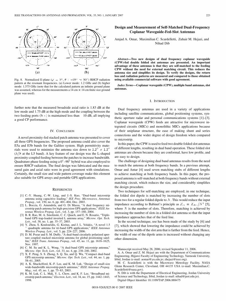
IEEE TRANSACTIONS ON ANTENNAS AND PROPAGATION, VOL. 55, NO. 1, JANUARY 2007 223
Fig. 8. Normalized E-plane (' = 0 , � : �90 � 90 ) RHCP radiationpattern at the resonant frequencies. (a) Lower mode: 1.2 GHz and (b) highermode: 1.575 GHz (note that for the calculated pattern an infinite ground planewas assumed, whereas for the measurements a 14 cm� 14 cm finite size groundplane was used).
further note that the measured broadside axial ratio is 1.83 dB at thelow mode and 1.75 dB at the high mode and the coupling between thetwo feeding ports (S12) is maintained less than �10 dB, all implyinga good CP performance.
IV. CONCLUSION
A novel proximity-fed stacked patch antenna was presented to coverall three GPS frequencies. The proposed antenna could also cover theE5a and E5b bands for the Galileo system. High permittivity mate-rials were used to minimize the antenna size down to 1:200 � 1:200
(�=8 at the L5 band). A key feature of our design was the L-shapedproximity-coupled feeding between the patches to increase bandwidth.Quadrature phase feeding using a 0�–90� hybrid was also employed toensure RHCP radiation. The final design was fabricated and the mea-sured gain and axial ratio were in good agreement with simulations.Certainly, the small size and wide pattern coverage make this elementalso suitable for GPS arrays and portable GPS applications.
REFERENCES
[1] C.-Y. Huang, C.-W. Ling, and J.-S. Kuo, “Dual-band microstripantenna using capacitive loading,” IEE Proc. Microwaves, AntennasPropag., vol. 150, no. 6, pp. 401–404, Dec. 2003.
[2] L. Boccia, G. Amendola, and G. Di Massa, “A dual frequency mi-crostrip patch antenna for high-precision GPS applications,” IEEE An-tennas Wireless Propag. Lett., vol. 3, pp. 157–160, 2004.
[3] B. R. Rao, M. A. Smolinski, C. C. Quach, and E. N. Rosario, “Triple-band GPS trap-loaded inverted L antenna array,” Microw. Opt. Tech.Lett., vol. 38, no. 1, pp. 35–37, 2003.
[4] Y. Zhou, S. Koulouridis, G. Kizitas, and J. L. Volakis, “A novel 1.5quadruple antenna for tri-band GPS applications,” IEEE Antennas
Wireless Propag. Lett., vol. 5, pp. 224–227, 2006.[5] D. M. Pozar and S. M. Duffy, “A dual-band circularly polarized aper-
ture coupled stacked microstrip antenna for global positioning satel-lite,” IEEE Trans. Antennas Propag., vol. 45, no. 11, pp. 1618–1625,Nov. 1997.
[6] C. M. Su and K. L. Wong, “A dual-band GPS microstrip antenna,”Microw. Opt. Tech. Lett., vol. 33, no. 4, pp. 238–240, 2002.
[7] X. F. Peng, S. S. Zhong, S. Q. Xu, and Q. Wu, “Compact dual-bandGPS microstrip antenna,” Microw. Opt. Tech. Lett., vol. 44, no. 1, pp.58–61, 2005.
[8] A. K. Shackelford, K.-F. Lee, and K. M. Luk, “Design of small-sizewide-bandwidth microstrip-patch antennas,” IEEE Antennas Propag.Mag., vol. 45, no. 1, pp. 75–83, 2003.
[9] K. M. Luk, C. L. Mak, Y. L. Chow, and K. F. Lee, “Broadband mi-crostrip patch antenna,” Electron. Lett., vol. 34, no. 15, pp. 1442–1443,1998.
Design and Measurement of Self-Matched Dual-FrequencyCoplanar Waveguide-Fed-Slot Antennas
Amjad A. Omar, Maximilian C. Scardelletti, Zuhair M. Hejazi, andNihad Dib
Abstract—Two new designs of dual frequency coplanar waveguide(CPW)-fed double folded slot antennas are presented. An importantadvantage of these antennas is that they are self-matched to the feedingCPW without the need for external matching circuit. This reduces theantenna size and simplifies its design. To verify the designs, the returnloss and radiation patterns are measured and compared to those obtainedusing available commercial software with good agreement.
Index Terms—Coplanar waveguide (CPW), multiple band antennas, slotantennas.
I. INTRODUCTION
Dual frequency antennas are used in a variety of applicationsincluding satellite communications, global positioning systems, syn-thetic aperture radar and personal communications systems [1]–[3].Coplanar waveguide (CPW) feeds are attractive for microwave in-tegrated circuits (MICs) and monolithic MICs applications becauseof their uniplanar structure, the ease of making shunt and seriesconnections and the wider degree of design freedom when comparedto microstrip.
In this paper, the CPW is used to feed two double folded slot antennasof different lengths, resulting in dual band operation. These folded slotantennas are chosen because they are conformal, have low profile, andare easy to design.
The challenge of designing dual band antennas results from the needto match the antenna at both frequency bands. In a previous attempt,Omar and Antar [4] used seven matching stubs of different lengthsto achieve matching at both frequency bands. In this paper, the pro-posed antenna is self-matched at both frequency bands without externalmatching circuit, which reduces the size, and considerably simplifiesthe design procedure.
Two techniques for self-matching are employed; in one technique,the folded slot dipole is matched by increasing the number of slotsfrom two for a regular folded dipole to N . This would reduce the inputimpedance according to Babinet’s principle as Zin = Zslot=N
2 [5],where N is the number of slots. Therefore, matching is achieved byincreasing the number of slots in a folded slot antenna so that the inputimpedance approaches that of the feed line.
In the second technique, use has been made of the study by [6] and[7], which showed that lowering the impedance could be achieved byincreasing the width of the slot arm that is farther from the feed. Hence,the width of one of the dipole arms is increased without changing anyother dimension.
Manuscript received May 28, 2006; revised September 11, 2006.A. A. Omar and Z. M. Hejazi are with the Department of Communications
Engineering, Hijjawi Faculty of Engineering Technology, Yarmouk University,Irbid, Jordan (e-mail: [email protected]; [email protected]).
M. C. Scardelletti is with the Microwave Metrology Facility, NASAGlenn Research Center, Cleveland, OH 44135 USA (e-mail: [email protected]).
N. Dib is with the Department of Electrical Engineering, Jordan Universityof Science and Technology, Irbid, Jordan (e-mail: [email protected]).
Digital Object Identifier 10.1109/TAP.2006.888475
0018-926X/$25.00 © 2007 IEEE

224 IEEE TRANSACTIONS ON ANTENNAS AND PROPAGATION, VOL. 55, NO. 1, JANUARY 2007
TABLE IEFFECT OF THE OUTER ARM WIDTH w ON S AND THE RESONANT FREQUENCIES f AND f
Fig. 1. CPW-fed dual-frequency slot antenna (W = 0:3 mm, S = 1:7 mm,S = 0:1 mm, S = 0:3 mm, S = 0:1 mm, W = 0:85 mm, c =
0:1 mm, b = b = b = w = 0:1 mm, L = 11:26 mm, L = 18:46 mm,h = 0:254 mm, " = 9:6).
Fig. 2. The experimental setup showing the coax-CPW transition.
II. DESIGN 1 ON ALUMINA ("r = 9:6)
The coplanar substrate chosen in this design is Alumina ("r = 9:6)with a thickness of 0.254 mm. The geometry of the antenna is shownin Fig. 1.
The design procedure is as follows.a) The feed line is designed using the moment method simulator
IE3D (of Zeland Inc.) to be a 50 ohm line on an Alumina substrateof 0.254 mm thickness. Hence, the slot width (w) is chosen to be
0.3 mm and the strip width (s) = 1:7 mm. These particulardimensions are chosen to give a better transition between thecoaxial connector and the CPW feed, as shown in Fig. 2.
b) The outer folded slot dipole is a regular folded slot dipole withtwo slot arms each having a length of approximately �1=2, where�1 is the guided wavelength of the CPW line at the lower resonantfrequency of 5 GHz. From IE3D, �1 = 34:7 mm, hence theinitial value of L0 is 17.35 mm. The width of each slot is chosento be 0.1 mm and can be slightly altered without affecting thedesign.
c) The inner folded slot dipole is initially designed in the same wayas for the outer loop using only two slot arms. Each arm hasa length of approximately �2=2, where �2 is the guided wave-length of the CPW line at the upper resonant frequency of 7 GHz.From IE3D, �2 = 24:8 mm, hence the initial value of L is12.4 mm. The width of each slot is also chosen to be 0.1 mm.
d) At this stage, an initial simulation of the design is carried outusing IE3D which showed that the lower resonant frequency isat 4.7 GHz instead of 5 GHz with a reflection coefficient jS11jof �3.54 dB. The upper resonant frequency is at 6.9 GHz withan jS11j of �5.18 dB.
e) To obtain a better match at the upper resonant frequency, a thirdslot is added to the inner smaller folded dipole as shown in Fig. 1resulting in a reduction of jS11j at the upper resonant frequencyfrom �5.18 to �14.24 dB at 6.76 GHz. At the lower frequency,jS11j has worsened to �2.76 dB.
f) To obtain a better match at the lower resonant frequency, thewidth (w0) of the outer slot of the larger folded dipole is increasedin repeated steps, as shown in Table I. From this table, w0 waschosen to be 0.85 mm.
g) Matching at both frequencies can be further improved by shiftingthe center slot arm of the smaller folded dipole away from thefeed. Hence, s00 is increased while s000 is decreased, as shown inFig. 1. Taking s00 = 0:3 mm, and s000 = 0:1 mm gives jS11j =�26:39 dB at f = 5:19 GHz, and jS11j = �37:79 dB atf = 6:73 GHz.
h) After few repeated simulations using IE3D, it is found that in-creasing the length of L0 to 18.46 mm, and decreasing the lengthof L to 11.26 mm result in more accurate resonant frequencies.
A. Measured and Simulated Results for Antenna on Alumina
The return loss was measured using the HP 8510 VNA and HP 2.4calibration standards. A comparison between measured and simulated

IEEE TRANSACTIONS ON ANTENNAS AND PROPAGATION, VOL. 55, NO. 1, JANUARY 2007 225
Fig. 3. Return loss of the CPW-fed-dual band antenna (design 1) (dimensionsare in Fig. 1).
Fig. 4. Measured radiation pattern of the dual-band antenna of Fig. 1 onAlumina at 5.0 GHz.
is shown in Fig. 3. The return loss was obtained experimentally, usingIE3D and the finite element simulator HFSS (of Ansoft Inc.). The re-sults obtained are in very good agreement, which verifies the design.The 10 dB bandwidth at both frequency bands is about 5%.
The co-polarization and cross-polarization gain patterns of this an-tenna in the E-plane (x � z plane) and H-plane (y � z plane) are alsomeasured and shown in Figs. 4 and 5 for the two measured center fre-quencies of 5.0 and 7.0 GHz, respectively. The antennas were mea-sured in the far-field range located in the Microwave Metrology Fa-cility at NASA Glenn Research Center, Cleveland, OH. A 2–18 GHzbroadband gain horn from Q-par Angus Ltd., U.K., was used to charac-terize the antenna gain patterns. These patterns show that the antennapossesses a linear polarization with cross polarization level more than
Fig. 5. Measured radiation pattern of the dual-band antenna of Fig. 1 onAlumina at 7.0 GHz.
Fig. 6. The dual band slot antenna (design 2) (w = 0:3 mm, s = 1:7 mm,s = 0:46 mm, w = 0:35, w = 1:36 mm, L = 16:7 mm, L =
22:57mm, c = b = 0:15 mm, " = 2:2, h = 3:175mm).
20 dBi lower than the co-polarization level. At 5.0 and 7.0 GHz, theantenna gain is about 3.5 dBi.
III. DESIGN 2 ON DUROID ("r = 2:2)
In this design, the chosen coplanar substrate is Duroid with a thick-ness of 3.18 mm and "r = 2:2. The geometry of the antenna is shownin Fig. 6. The design procedure is similar to that in Section II. The outerfolded slot dipole is a regular folded slot dipole with 2 slots arms eachhaving a length ofL0 = 22:57mm and a width of 0.15 mm. This dipoleresonates at 4.7 GHz. The impedance of this dipole is about 128 . Tomatch this antenna to the 70 feeding CPW (strip width = 1:7 mmand slot width = 0:3 mm), the width of the external slot arm of thedipole (w00) is increased from 0.15 to 1.36 mm.
The difference between design 1 and 2 is that in the latter, the innerfolded slot dipole consists of 2 slot arms only. Each arm has a lengthof 16.7 mm and a width of 0.15 mm. The width w0 of the outer arm
226 IEEE TRANSACTIONS ON ANTENNAS AND PROPAGATION, VOL. 55, NO. 1, JANUARY 2007
Fig. 7. Return loss for the antenna of design 2 on Duroid (dimensions are inFig. 6).
Fig. 8. Measured radiation pattern of design 2 at 4.7 GHz.
of the inner slot is increased from 0.15 mm to 0.35 mm for matchingpurposes. This dipole resonates at 7.1 GHz.
A. Measured and Simulated Results for Antenna on Duroid
The measured and IE3D simulated return loss of this antenna are il-lustrated in Fig. 7. The two resonances are at 4.7 and 7.1 GHz with ameasured return loss of 20 and 15 dB, respectively. The 10 dB band-width at both frequency bands is about 4%.
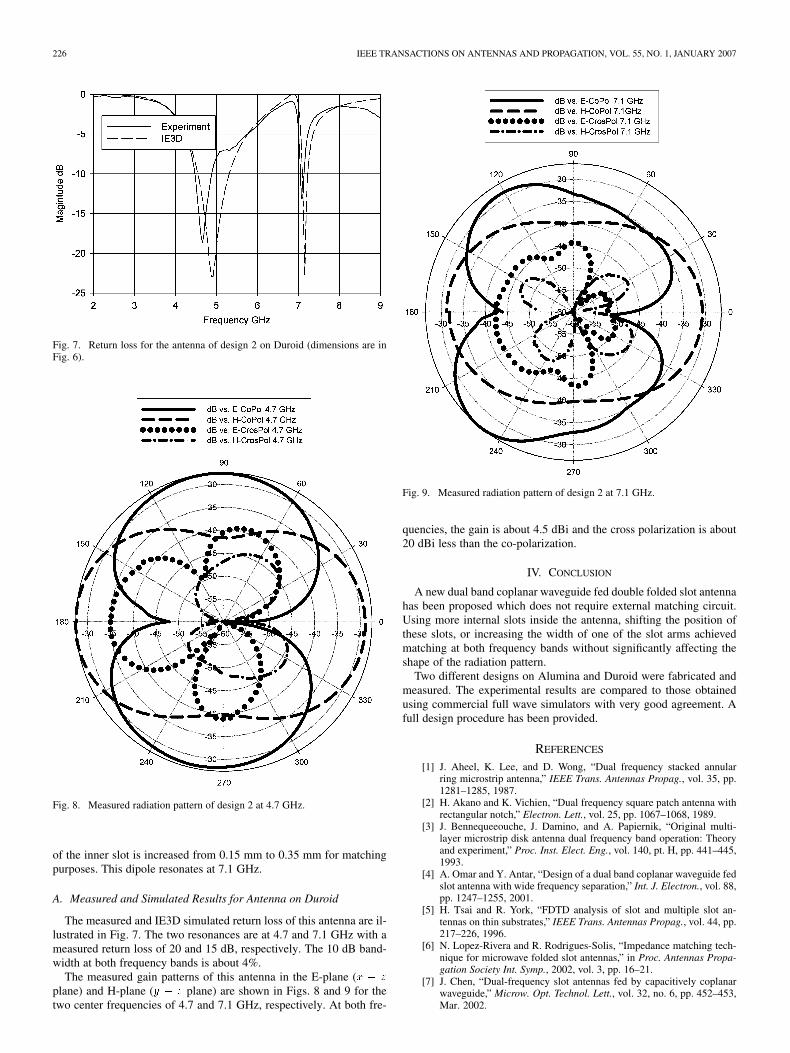
The measured gain patterns of this antenna in the E-plane (x � z
plane) and H-plane (y � z plane) are shown in Figs. 8 and 9 for thetwo center frequencies of 4.7 and 7.1 GHz, respectively. At both fre-
Fig. 9. Measured radiation pattern of design 2 at 7.1 GHz.
quencies, the gain is about 4.5 dBi and the cross polarization is about20 dBi less than the co-polarization.
IV. CONCLUSION
A new dual band coplanar waveguide fed double folded slot antennahas been proposed which does not require external matching circuit.Using more internal slots inside the antenna, shifting the position ofthese slots, or increasing the width of one of the slot arms achievedmatching at both frequency bands without significantly affecting theshape of the radiation pattern.
Two different designs on Alumina and Duroid were fabricated andmeasured. The experimental results are compared to those obtainedusing commercial full wave simulators with very good agreement. Afull design procedure has been provided.
REFERENCES
[1] J. Aheel, K. Lee, and D. Wong, “Dual frequency stacked annularring microstrip antenna,” IEEE Trans. Antennas Propag., vol. 35, pp.1281–1285, 1987.
[2] H. Akano and K. Vichien, “Dual frequency square patch antenna withrectangular notch,” Electron. Lett., vol. 25, pp. 1067–1068, 1989.
[3] J. Bennequeeouche, J. Damino, and A. Papiernik, “Original multi-layer microstrip disk antenna dual frequency band operation: Theoryand experiment,” Proc. Inst. Elect. Eng., vol. 140, pt. H, pp. 441–445,1993.
[4] A. Omar and Y. Antar, “Design of a dual band coplanar waveguide fedslot antenna with wide frequency separation,” Int. J. Electron., vol. 88,pp. 1247–1255, 2001.
[5] H. Tsai and R. York, “FDTD analysis of slot and multiple slot an-tennas on thin substrates,” IEEE Trans. Antennas Propag., vol. 44, pp.217–226, 1996.
[6] N. Lopez-Rivera and R. Rodrigues-Solis, “Impedance matching tech-nique for microwave folded slot antennas,” in Proc. Antennas Propa-gation Society Int. Symp., 2002, vol. 3, pp. 16–21.
[7] J. Chen, “Dual-frequency slot antennas fed by capacitively coplanarwaveguide,” Microw. Opt. Technol. Lett., vol. 32, no. 6, pp. 452–453,Mar. 2002.