Section 43. Quadrature Encoder Interface...
32
© 2015 Microchip Technology Inc. Preliminary DS60001346A-page 43-1 Quadrature Encoder Interface (QEI) 43 Section 43. Quadrature Encoder Interface (QEI) HIGHLIGHTS This section of the manual contains the following major topics: 43.1 Introduction .................................................................................................................. 43-2 43.2 Control and Status Registers ....................................................................................... 43-5 43.3 Module Description .................................................................................................... 43-19 43.4 QEI Operation in Power-Saving Modes ..................................................................... 43-27 43.5 Effects of a Reset ....................................................................................................... 43-27 43.6 Related Application Notes.......................................................................................... 43-28 43.7 Revision History ......................................................................................................... 43-29
Transcript of Section 43. Quadrature Encoder Interface...
Section 43. Quadrature Encoder Interface (QEI)
Qu
adratu
re E
nco
der In
terface(Q
EI)
43
HIGHLIGHTS
This section of the manual contains the following major topics:
43.1 Introduction .................................................................................................................. 43-2
43.2 Control and Status Registers .......................................................................................43-5
43.3 Module Description ....................................................................................................43-19
43.4 QEI Operation in Power-Saving Modes ..................................................................... 43-27
43.5 Effects of a Reset.......................................................................................................43-27
43.6 Related Application Notes..........................................................................................43-28
43.7 Revision History .........................................................................................................43-29
© 2015 Microchip Technology Inc. Preliminary DS60001346A-page 43-1
PIC32 Family Reference Manual
43.1 INTRODUCTION
The Quadrature Encoder Interface (QEI) module provides the interface to incremental encoders for obtaining mechanical position data. Quadrature encoders, also known as incremental encoders or optical encoders, detect position and speed of rotating motion systems. Quadrature encoders enable closed-loop control of motor control applications, such as Switched Reluctance (SR) and AC Induction Motors (ACIM).
A typical quadrature encoder includes a slotted wheel attached to the shaft of the motor and an Emitter/Detector module that senses the slots in the wheel. Typically, three output channels, Phase A (QEA), Phase B (QEB) and Index (INDX) provide information on the movement of the motor shaft, including distance and direction.
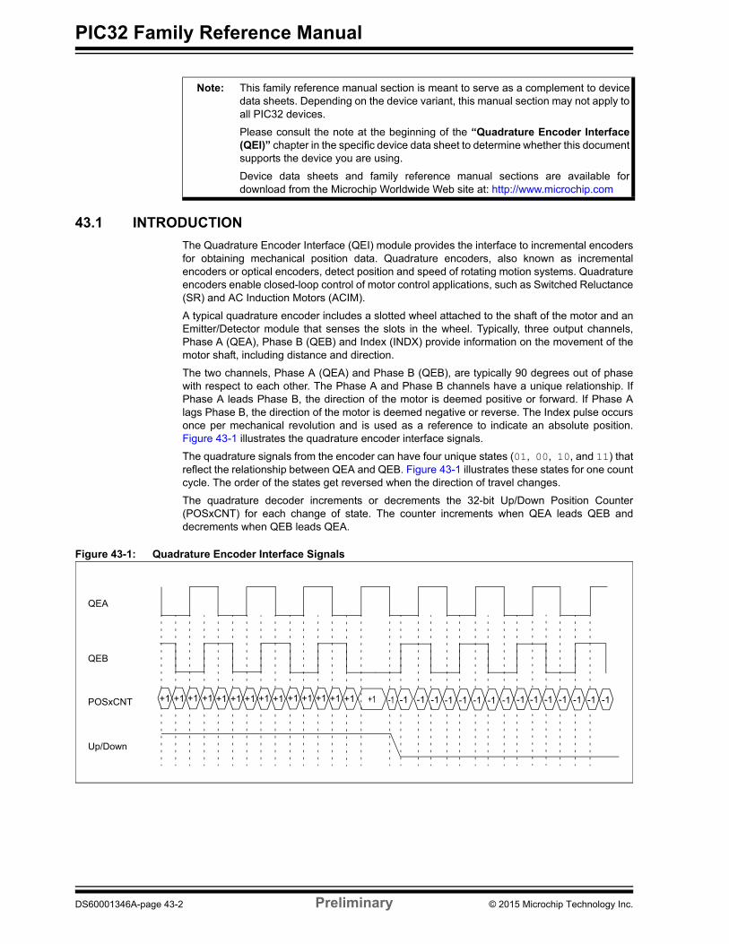
The two channels, Phase A (QEA) and Phase B (QEB), are typically 90 degrees out of phase with respect to each other. The Phase A and Phase B channels have a unique relationship. If Phase A leads Phase B, the direction of the motor is deemed positive or forward. If Phase A lags Phase B, the direction of the motor is deemed negative or reverse. The Index pulse occurs once per mechanical revolution and is used as a reference to indicate an absolute position. Figure 43-1 illustrates the quadrature encoder interface signals.
The quadrature signals from the encoder can have four unique states (01, 00, 10, and 11) that reflect the relationship between QEA and QEB. Figure 43-1 illustrates these states for one count cycle. The order of the states get reversed when the direction of travel changes.
The quadrature decoder increments or decrements the 32-bit Up/Down Position Counter (POSxCNT) for each change of state. The counter increments when QEA leads QEB and decrements when QEB leads QEA.
Figure 43-1: Quadrature Encoder Interface Signals
+1+1 +1 +1 +1 +1 +1 +1 +1 +1 +1 +1 +1 +1 +1 -1 -1 -1 -1 -1 -1 -1 -1 -1 -1 -1 -1 -1 -1 -1POSxCNT
Up/Down
QEA
QEB
-1
Note: This family reference manual section is meant to serve as a complement to device data sheets. Depending on the device variant, this manual section may not apply to all PIC32 devices.
Please consult the note at the beginning of the “Quadrature Encoder Interface (QEI)” chapter in the specific device data sheet to determine whether this document supports the device you are using.
Device data sheets and family reference manual sections are available for download from the Microchip Worldwide Web site at: http://www.microchip.com
DS60001346A-page 43-2 Preliminary © 2015 Microchip Technology Inc.
Section 43. Quadrature Encoder Interface (QEI)Q
uad
rature
En
cod
er Interface
(QE
I)
43
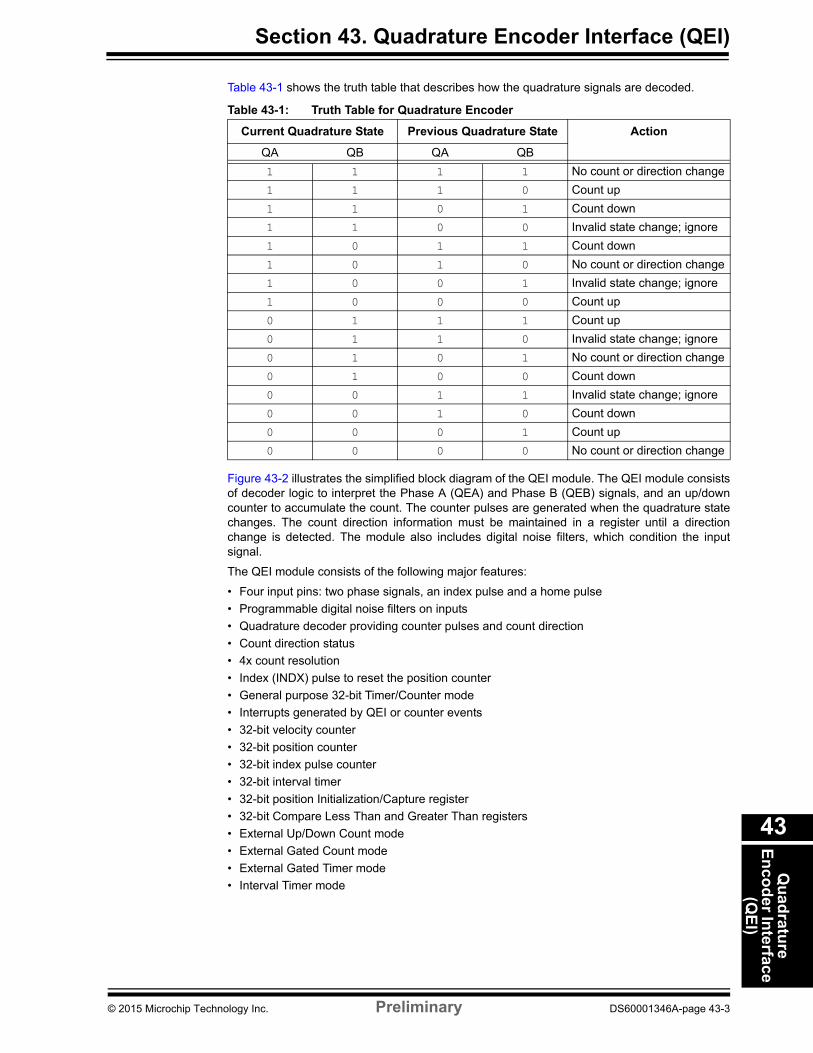
Table 43-1 shows the truth table that describes how the quadrature signals are decoded.
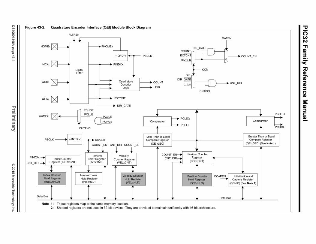
Figure 43-2 illustrates the simplified block diagram of the QEI module. The QEI module consists of decoder logic to interpret the Phase A (QEA) and Phase B (QEB) signals, and an up/down counter to accumulate the count. The counter pulses are generated when the quadrature state changes. The count direction information must be maintained in a register until a direction change is detected. The module also includes digital noise filters, which condition the input signal.
The QEI module consists of the following major features:
• Four input pins: two phase signals, an index pulse and a home pulse
• Programmable digital noise filters on inputs
• Quadrature decoder providing counter pulses and count direction
• Count direction status
• 4x count resolution
• Index (INDX) pulse to reset the position counter
• General purpose 32-bit Timer/Counter mode
• Interrupts generated by QEI or counter events
• 32-bit velocity counter
• 32-bit position counter
• 32-bit index pulse counter
• 32-bit interval timer
• 32-bit position Initialization/Capture register
• 32-bit Compare Less Than and Greater Than registers
• External Up/Down Count mode
• External Gated Count mode
• External Gated Timer mode
• Interval Timer mode
Table 43-1: Truth Table for Quadrature Encoder
Current Quadrature State Previous Quadrature State Action
QA QB QA QB
1 1 1 1 No count or direction change
1 1 1 0 Count up
1 1 0 1 Count down
1 1 0 0 Invalid state change; ignore
1 0 1 1 Count down
1 0 1 0 No count or direction change
1 0 0 1 Invalid state change; ignore
1 0 0 0 Count up
0 1 1 1 Count up
0 1 1 0 Invalid state change; ignore
0 1 0 1 No count or direction change
0 1 0 0 Count down
0 0 1 1 Invalid state change; ignore
0 0 1 0 Count down
0 0 0 1 Count up
0 0 0 0 No count or direction change
© 2015 Microchip Technology Inc. Preliminary DS60001346A-page 43-3
PIC
32 Fam
ily Referen
ce Man
ual
DS
60001346A
-page 43-4
Prelim
ina
ry©
2015 Microchip T
echnology Inc.
COUNT_EN
Greater Than or EqualCompare Register
Comparator
Data Bus
PCHEQ
PCHGE
CNT_DIR
GATEN
0
1
(QEIxGEC) (See Note 1)
Initialization and Capture Register
(QEIxIC) (See Note 1)
APEN
Figure 43-2: Quadrature Encoder Interface (QEI) Module Block Diagram
QuadratureDecoder
Logic
CCMPx
QEBx
QEAx
INDXx
COUNT
DIR
PBCLK
COUNT
Index Counter
DigitalFilter
HOMEx FHOMEx
Data Bus
COUNT_ENCNT_DIR
CNT_DIR
FINDXx
FINDXx
Interval TimerIndex Counter Hold Register
IntervalTimer Register
Hold Register
COUNT_EN
PBCLK
EXTCNT
EXTCNT
DIR_GATE
Velocity
COUNT_ENCNT_DIR
Counter Register
PCLLE
PCHGE
DIVCLK
DIR
DIR_GATE
1’b0
PCLLE
CNTPOL
DIR_GATE
DIVCLK
Comparator PCLLE
PCLEQPCHGE
QFDIV
CCM
INTDIV
(VELxCNT)(INTxTMR)
(INTxHLD)
Register (INDXxCNT)
(INDXxHLD)
Less Than or EqualCompare Register
(QEIxLEC)
Position CounterHold Register(POSxHLD)
QC
Note 1: These registers map to the same memory location.2: Shaded registers are not used in 32-bit devices. They are provided to maintain uniformity with 16-bit architecture.
OUTFNC
FLTREN
Velocity CounterHold Register(VELxHLD)
Position CounterRegister
(POSxCNT)
Section 43. Quadrature Encoder Interface (QEI)Q
uad
rature
En
cod
er Interface
(QE
I)
43
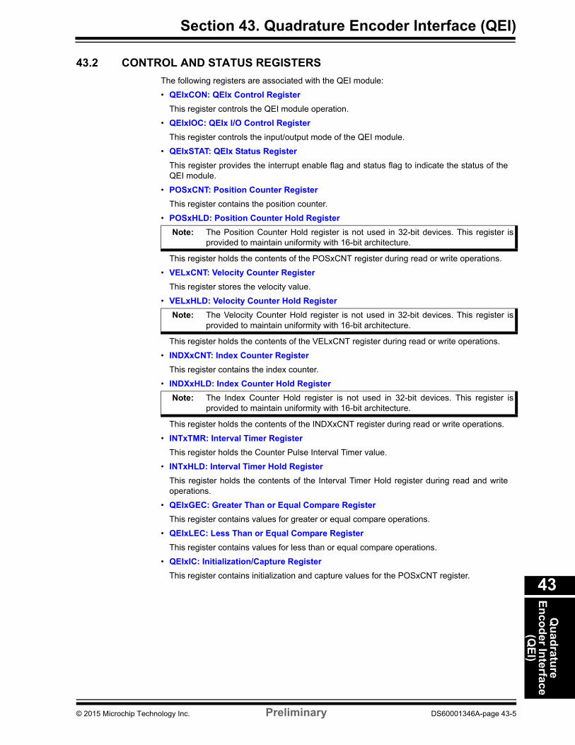
43.2 CONTROL AND STATUS REGISTERS
The following registers are associated with the QEI module:
• QEIxCON: QEIx Control Register
This register controls the QEI module operation.
• QEIxIOC: QEIx I/O Control Register
This register controls the input/output mode of the QEI module.
• QEIxSTAT: QEIx Status Register
This register provides the interrupt enable flag and status flag to indicate the status of the QEI module.
• POSxCNT: Position Counter Register
This register contains the position counter.
• POSxHLD: Position Counter Hold Register
Note: The Position Counter Hold register is not used in 32-bit devices. This register is provided to maintain uniformity with 16-bit architecture.
This register holds the contents of the POSxCNT register during read or write operations.
• VELxCNT: Velocity Counter Register
This register stores the velocity value.
• VELxHLD: Velocity Counter Hold Register
Note: The Velocity Counter Hold register is not used in 32-bit devices. This register is provided to maintain uniformity with 16-bit architecture.
This register holds the contents of the VELxCNT register during read or write operations.
• INDXxCNT: Index Counter Register
This register contains the index counter.
• INDXxHLD: Index Counter Hold Register
Note: The Index Counter Hold register is not used in 32-bit devices. This register is provided to maintain uniformity with 16-bit architecture.
This register holds the contents of the INDXxCNT register during read or write operations.
• INTxTMR: Interval Timer Register
This register holds the Counter Pulse Interval Timer value.
• INTxHLD: Interval Timer Hold Register
This register holds the contents of the Interval Timer Hold register during read and write operations.
• QEIxGEC: Greater Than or Equal Compare Register
This register contains values for greater or equal compare operations.
• QEIxLEC: Less Than or Equal Compare Register
This register contains values for less than or equal compare operations.
• QEIxIC: Initialization/Capture Register
This register contains initialization and capture values for the POSxCNT register.
© 2015 Microchip Technology Inc. Preliminary DS60001346A-page 43-5
PIC
32 Fam
ily Referen
ce Man
ual
DS
60001346A
-page 43-6
Prelim
ina
ry©
2015 Microchip T
echnology Inc.
ummaries, followed by a detailed description of
Bit 20/4 Bit 19/3 Bit 18/2 Bit 17/1 Bit 16/0
— — — — —
CNTPOL GATEN CCM<1:0>
— — — — HCAPEN
QEAPOL HOME INDEX QEB QEA
— — — — —
VELOVIEN HOMIRQ HOMIEN IDXIRQ IDXIEN
ectively. These registers have the same name, with CLR, invert valid bits in the associated register. Reads from the
ure.
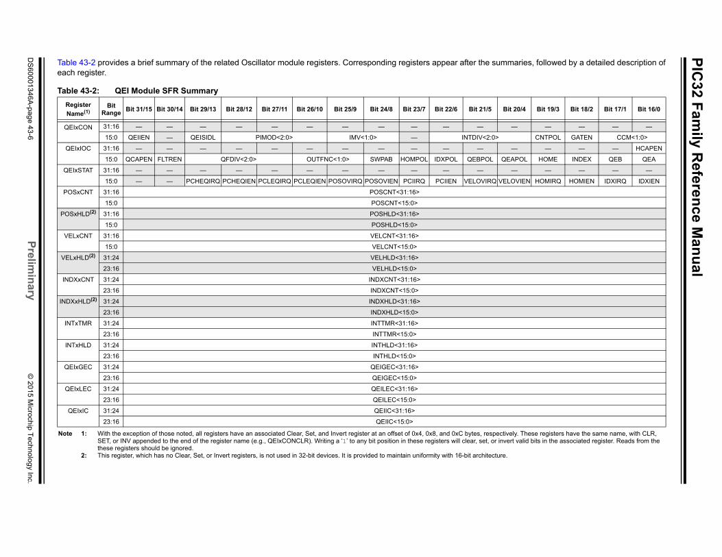
Table 43-2 provides a brief summary of the related Oscillator module registers. Corresponding registers appear after the seach register.
Table 43-2: QEI Module SFR Summary
Register
Name(1)Bit
RangeBit 31/15 Bit 30/14 Bit 29/13 Bit 28/12 Bit 27/11 Bit 26/10 Bit 25/9 Bit 24/8 Bit 23/7 Bit 22/6 Bit 21/5
QEIxCON 31:16 — — — — — — — — — — —
15:0 QEIIEN — QEISIDL PIMOD<2:0> IMV<1:0> — INTDIV<2:0>
QEIxIOC 31:16 — — — — — — — — — — —
15:0 QCAPEN FLTREN QFDIV<2:0> OUTFNC<1:0> SWPAB HOMPOL IDXPOL QEBPOL
QEIxSTAT 31:16 — — — — — — — — — — —
15:0 — — PCHEQIRQ PCHEQIEN PCLEQIRQ PCLEQIEN POSOVIRQ POSOVIEN PCIIRQ PCIIEN VELOVIRQ
POSxCNT 31:16 POSCNT<31:16>
15:0 POSCNT<15:0>
POSxHLD(2) 31:16 POSHLD<31:16>
15:0 POSHLD<15:0>
VELxCNT 31:16 VELCNT<31:16>
15:0 VELCNT<15:0>
VELxHLD(2) 31:24 VELHLD<31:16>
23:16 VELHLD<15:0>
INDXxCNT 31:24 INDXCNT<31:16>
23:16 INDXCNT<15:0>
INDXxHLD(2) 31:24 INDXHLD<31:16>
23:16 INDXHLD<15:0>
INTxTMR 31:24 INTTMR<31:16>
23:16 INTTMR<15:0>
INTxHLD 31:24 INTHLD<31:16>
23:16 INTHLD<15:0>
QEIxGEC 31:24 QEIGEC<31:16>
23:16 QEIGEC<15:0>
QEIxLEC 31:24 QEILEC<31:16>
23:16 QEILEC<15:0>
QEIxIC 31:24 QEIIC<31:16>
23:16 QEIIC<15:0>
Note 1: With the exception of those noted, all registers have an associated Clear, Set, and Invert register at an offset of 0x4, 0x8, and 0xC bytes, respSET, or INV appended to the end of the register name (e.g., QEIxCONCLR). Writing a ‘1’ to any bit position in these registers will clear, set, orthese registers should be ignored.
2: This register, which has no Clear, Set, or Invert registers, is not used in 32-bit devices. It is provided to maintain uniformity with 16-bit architect
Section 43. Quadrature Encoder Interface (QEI)Q
uad
rature
En
cod
er Interface
(QE
I)
43
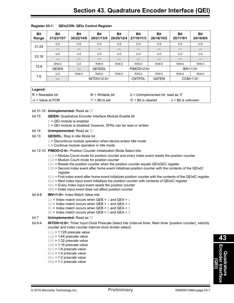
Register 43-1: QEIxCON: QEIx Control Register
Bit Range
Bit31/23/15/7
Bit30/22/14/6
Bit29/21/13/5
Bit28/20/12/4
Bit27/19/11/3
Bit26/18/10/2
Bit25/17/9/1
Bit24/16/8/0
31:24U-0 U-0 U-0 U-0 U-0 U-0 U-0 U-0
— — — — — — — —
23:16U-0 U-0 U-0 U-0 U-0 U-0 U-0 U-0
— — — — — — — —
15:8R/W-0 U-0 R/W-0 R/W-0 R/W-0 R/W-0 R/W-0 R/W-0
QEIEN — QEISIDL PIMOD<2:0> IMV<1:0>
7:0U-0 R/W-0 R/W-0 R/W-0 R/W-0 R/W-0 R/W-0 R/W-0
— INTDIV<2:0> CNTPOL GATEN CCM<1:0>
Legend:
R = Readable bit W = Writable bit U = Unimplemented bit, read as ‘0’
-n = Value at POR ‘1’ = Bit is set ‘0’ = Bit is cleared x = Bit is unknown
bit 31-16 Unimplemented: Read as ‘0’
bit 15 QEIEN: Quadrature Encoder Interface Module Enable bit
1 = QEI module is enabled0 = QEI module is disabled; however, SFRs can be read or written
bit 14 Unimplemented: Read as ‘0’
bit 13 QEISIDL: Stop in Idle Mode bit
1 = Discontinue module operation when device enters Idle mode0 = Continue module operation in Idle mode
bit 12-10 PIMOD<2:0>: Position Counter Initialization Mode Select bits
111 = Modulo Count mode for position counter and every index event resets the position counter110 = Modulo Count mode for position counter101 = Resets the position counter when the position counter equals QEIxGEC register 100 = Second index event after home event initializes position counter with the contents of the QEIxIC
register011 = First index event after home event initializes position counter with the contents of the QEIxIC register010 = Next index input event initializes the position counter with contents of QEIxIC register001 = Every Index input event resets the position counter000 = Index input event does not affect position counter
bit 9-8 IMV<1:0>: Index Match Value bits
11 = Index match occurs when QEB = 1 and QEA = 1 10 = Index match occurs when QEB = 1 and QEA = 0 01 = Index match occurs when QEB = 0 and QEA = 1 00 = Index match occurs when QEB = 0 and QEA = 0
bit 7 Unimplemented: Read as ‘0’
bit 6-4 INTDIV<2:0>: Timer Input Clock Prescale Select bits (Interval timer, Main timer (position counter), velocity counter and index counter internal clock divider select)
111 = 1:128 prescale value110 = 1:64 prescale value101 = 1:32 prescale value100 = 1:16 prescale value011 = 1:8 prescale value010 = 1:4 prescale value001 = 1:2 prescale value000 = 1:1 prescale value
© 2015 Microchip Technology Inc. Preliminary DS60001346A-page 43-7
PIC32 Family Reference Manual
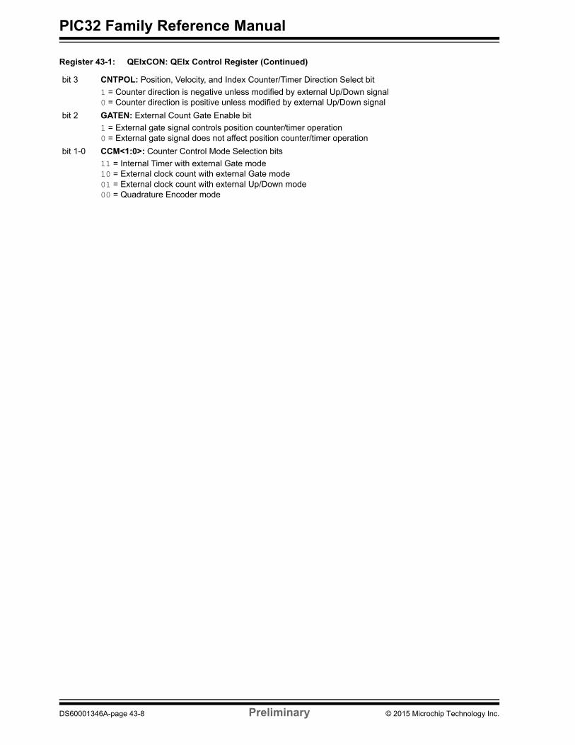
bit 3 CNTPOL: Position, Velocity, and Index Counter/Timer Direction Select bit
1 = Counter direction is negative unless modified by external Up/Down signal0 = Counter direction is positive unless modified by external Up/Down signal
bit 2 GATEN: External Count Gate Enable bit
1 = External gate signal controls position counter/timer operation0 = External gate signal does not affect position counter/timer operation
bit 1-0 CCM<1:0>: Counter Control Mode Selection bits
11 = Internal Timer with external Gate mode10 = External clock count with external Gate mode01 = External clock count with external Up/Down mode00 = Quadrature Encoder mode
Register 43-1: QEIxCON: QEIx Control Register (Continued)
DS60001346A-page 43-8 Preliminary © 2015 Microchip Technology Inc.
Section 43. Quadrature Encoder Interface (QEI)Q
uad
rature
En
cod
er Interface
(QE
I)
43
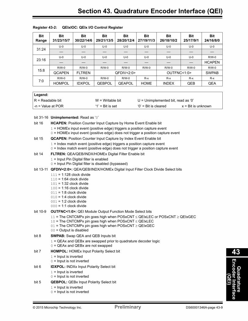
Register 43-2: QEIxIOC: QEIx I/O Control Register
Bit Range
Bit31/23/15/7
Bit30/22/14/6
Bit29/21/13/5
Bit28/20/12/4
Bit27/19/11/3
Bit26/18/10/2
Bit25/17/9/1
Bit24/16/8/0
31:24U-0 U-0 U-0 U-0 U-0 U-0 U-0 U-0
— — — — — — — —
23:16U-0 U-0 U-0 U-0 U-0 U-0 U-0 R/W-0
— — — — — — — HCAPEN
15:8R/W-0 R/W-0 R/W-0 R/W-0 R/W-0 R/W-0 R/W-0 R/W-0
QCAPEN FLTREN QFDIV<2:0> OUTFNC<1:0> SWPAB
7:0R/W-0 R/W-0 R/W-0 R/W-0 R-x R-x R-x R-x
HOMPOL IDXPOL QEBPOL QEAPOL HOME INDEX QEB QEA
Legend:
R = Readable bit W = Writable bit U = Unimplemented bit, read as ‘0’
-n = Value at POR ‘1’ = Bit is set ‘0’ = Bit is cleared x = Bit is unknown
bit 31-16 Unimplemented: Read as ‘0’
bit 16 HCAPEN: Position Counter Input Capture by Home Event Enable bit
1 = HOMEx input event (positive edge) triggers a position capture event0 = HOMEx input event (positive edge) does not trigger a position capture event
bit 15 QCAPEN: Position Counter Input Capture by Index Event Enable bit
1 = Index match event (positive edge) triggers a position capture event0 = Index match event (positive edge) does not trigger a position capture event
bit 14 FLTREN: QEA/QEB/INDX/HOMEx Digital Filter Enable bit
1 = Input Pin Digital filter is enabled0 = Input Pin Digital filter is disabled (bypassed)
bit 13-11 QFDIV<2:0>: QEA/QEB/INDX/HOMEx Digital Input Filter Clock Divide Select bits
111 = 1:128 clock divide110 = 1:64 clock divide101 = 1:32 clock divide100 = 1:16 clock divide011 = 1:8 clock divide010 = 1:4 clock divide001 = 1:2 clock divide000 = 1:1 clock divide
bit 10-9 OUTFNC<1:0>: QEI Module Output Function Mode Select bits
11 = The CNTCMPx pin goes high when POSxCNT QEIxLEC or POSxCNT QEIxGEC10 = The CNTCMPx pin goes high when POSxCNT QEIxLEC01 = The CNTCMPx pin goes high when POSxCNT QEIxGEC00 = Output is disabled
bit 8 SWPAB: Swap QEA and QEB Inputs bit
1 = QEAx and QEBx are swapped prior to quadrature decoder logic0 = QEAx and QEBx are not swapped
bit 7 HOMPOL: HOMEx Input Polarity Select bit
1 = Input is inverted0 = Input is not inverted
bit 6 IDXPOL: INDXx Input Polarity Select bit
1 = Input is inverted0 = Input is not inverted
bit 5 QEBPOL: QEBx Input Polarity Select bit
1 = Input is inverted0 = Input is not inverted
© 2015 Microchip Technology Inc. Preliminary DS60001346A-page 43-9
PIC32 Family Reference Manual
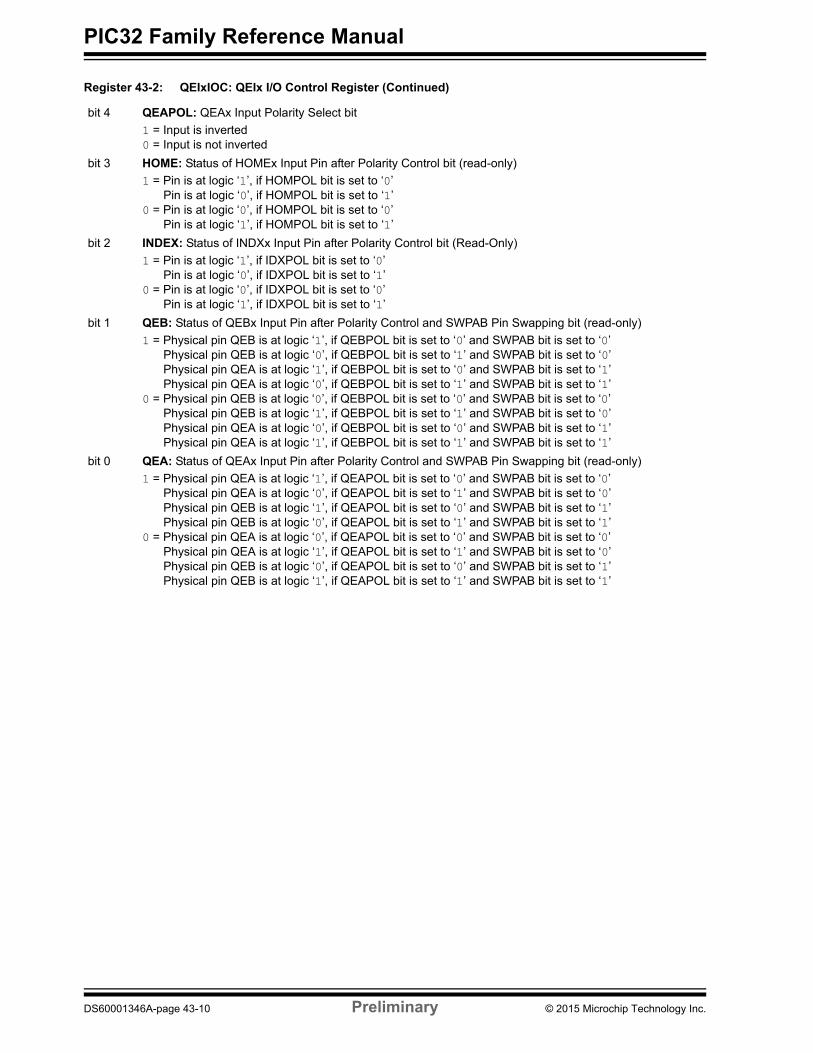
bit 4 QEAPOL: QEAx Input Polarity Select bit
1 = Input is inverted0 = Input is not inverted
bit 3 HOME: Status of HOMEx Input Pin after Polarity Control bit (read-only)
1 = Pin is at logic ‘1’, if HOMPOL bit is set to ‘0’Pin is at logic ‘0’, if HOMPOL bit is set to ‘1’
0 = Pin is at logic ‘0’, if HOMPOL bit is set to ‘0’Pin is at logic ‘1’, if HOMPOL bit is set to ‘1’
bit 2 INDEX: Status of INDXx Input Pin after Polarity Control bit (Read-Only)
1 = Pin is at logic ‘1’, if IDXPOL bit is set to ‘0’Pin is at logic ‘0’, if IDXPOL bit is set to ‘1’
0 = Pin is at logic ‘0’, if IDXPOL bit is set to ‘0’Pin is at logic ‘1’, if IDXPOL bit is set to ‘1’
bit 1 QEB: Status of QEBx Input Pin after Polarity Control and SWPAB Pin Swapping bit (read-only)
1 = Physical pin QEB is at logic ‘1’, if QEBPOL bit is set to ‘0’ and SWPAB bit is set to ‘0’Physical pin QEB is at logic ‘0’, if QEBPOL bit is set to ‘1’ and SWPAB bit is set to ‘0’Physical pin QEA is at logic ‘1’, if QEBPOL bit is set to ‘0’ and SWPAB bit is set to ‘1’Physical pin QEA is at logic ‘0’, if QEBPOL bit is set to ‘1’ and SWPAB bit is set to ‘1’
0 = Physical pin QEB is at logic ‘0’, if QEBPOL bit is set to ‘0’ and SWPAB bit is set to ‘0’Physical pin QEB is at logic ‘1’, if QEBPOL bit is set to ‘1’ and SWPAB bit is set to ‘0’Physical pin QEA is at logic ‘0’, if QEBPOL bit is set to ‘0’ and SWPAB bit is set to ‘1’Physical pin QEA is at logic ‘1’, if QEBPOL bit is set to ‘1’ and SWPAB bit is set to ‘1’
bit 0 QEA: Status of QEAx Input Pin after Polarity Control and SWPAB Pin Swapping bit (read-only)
1 = Physical pin QEA is at logic ‘1’, if QEAPOL bit is set to ‘0’ and SWPAB bit is set to ‘0’Physical pin QEA is at logic ‘0’, if QEAPOL bit is set to ‘1’ and SWPAB bit is set to ‘0’Physical pin QEB is at logic ‘1’, if QEAPOL bit is set to ‘0’ and SWPAB bit is set to ‘1’Physical pin QEB is at logic ‘0’, if QEAPOL bit is set to ‘1’ and SWPAB bit is set to ‘1’
0 = Physical pin QEA is at logic ‘0’, if QEAPOL bit is set to ‘0’ and SWPAB bit is set to ‘0’Physical pin QEA is at logic ‘1’, if QEAPOL bit is set to ‘1’ and SWPAB bit is set to ‘0’Physical pin QEB is at logic ‘0’, if QEAPOL bit is set to ‘0’ and SWPAB bit is set to ‘1’Physical pin QEB is at logic ‘1’, if QEAPOL bit is set to ‘1’ and SWPAB bit is set to ‘1’
Register 43-2: QEIxIOC: QEIx I/O Control Register (Continued)
DS60001346A-page 43-10 Preliminary © 2015 Microchip Technology Inc.
Section 43. Quadrature Encoder Interface (QEI)Q
uad
rature
En
cod
er Interface
(QE
I)
43
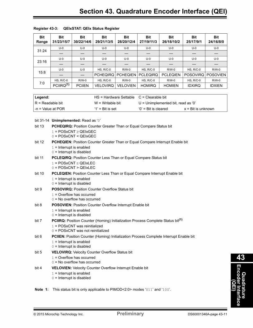
Register 43-3: QEIxSTAT: QEIx Status Register
Bit Range
Bit31/23/15/7
Bit30/22/14/6
Bit29/21/13/5
Bit28/20/12/4
Bit27/19/11/3
Bit26/18/10/2
Bit25/17/9/1
Bit24/16/8/0
31:24U-0 U-0 U-0 U-0 U-0 U-0 U-0 U-0
— — — — — — — —
23:16U-0 U-0 U-0 U-0 U-0 U-0 U-0 U-0
— — — — — — — —
15:8U-0 U-0 HS, R/C-0 R/W-0 HS, R/C-0 R/W-0 HS, R/C-0 R/W-0
— — PCHEQIRQ PCHEQIEN PCLEQIRQ PCLEQIEN POSOVIRQ POSOVIEN
7:0HS, R/C-0 R/W-0 HS, R/C-0 R/W-0 HS, R/C-0 R/W-0 HS, R/C-0 R/W-0
PCIIRQ(1) PCIIEN VELOVIRQ VELOVIEN HOMIRQ HOMIEN IDXIRQ IDXIEN
Legend: HS = Hardware Settable C = Clearable bit
R = Readable bit W = Writable bit U = Unimplemented bit, read as ‘0’
-n = Value at POR ‘1’ = Bit is set ‘0’ = Bit is cleared x = Bit is unknown
bit 31-14 Unimplemented: Read as ‘0’
bit 13 PCHEQIRQ: Position Counter Greater Than or Equal Compare Status bit
1 = POSxCNT QEIxGEC0 = POSxCNT < QEIxGEC
bit 12 PCHEQIEN: Position Counter Greater Than or Equal Compare Interrupt Enable bit
1 = Interrupt is enabled0 = Interrupt is disabled
bit 11 PCLEQIRQ: Position Counter Less Than or Equal Compare Status bit
1 = POSxCNT QEIxLEC0 = POSxCNT > QEIxLEC
bit 10 PCLEQIEN: Position Counter Less Than or Equal Compare Interrupt Enable bit
1 = Interrupt is enabled0 = Interrupt is disabled
bit 9 POSOVIRQ: Position Counter Overflow Status bit
1 = Overflow has occurred0 = No overflow has occurred
bit 8 POSOVIEN: Position Counter Overflow Interrupt Enable bit
1 = Interrupt is enabled0 = Interrupt is disabled
bit 7 PCIIRQ: Position Counter (Homing) Initialization Process Complete Status bit(1)
1 = POSxCNT was reinitialized0 = POSxCNT was not reinitialized
bit 6 PCIIEN: Position Counter (Homing) Initialization Process Complete Interrupt Enable bit
1 = Interrupt is enabled0 = Interrupt is disabled
bit 5 VELOVIRQ: Velocity Counter Overflow Status bit
1 = Overflow has occurred0 = No overflow has occurred
bit 4 VELOVIEN: Velocity Counter Overflow Interrupt Enable bit
1 = Interrupt is enabled0 = Interrupt is disabled
Note 1: This status bit is only applicable to PIMOD<2:0> modes ‘011’ and ‘100’.
© 2015 Microchip Technology Inc. Preliminary DS60001346A-page 43-11
PIC32 Family Reference Manual
bit 3 HOMIRQ: Status Flag for Home Event Status bit
1 = Home event has occurred0 = No Home event has occurred
bit 2 HOMIEN: Home Input Event Interrupt Enable bit
1 = Interrupt is enabled0 = Interrupt is disabled
bit 1 IDXIRQ: Status Flag for Index Event Status bit
1 = Index event has occurred0 = No Index event has occurred
bit 0 IDXIEN: Index Input Event Interrupt Enable bit
1 = Interrupt is enabled0 = Interrupt is disabled
Register 43-3: QEIxSTAT: QEIx Status Register (Continued)
Note 1: This status bit is only applicable to PIMOD<2:0> modes ‘011’ and ‘100’.
DS60001346A-page 43-12 Preliminary © 2015 Microchip Technology Inc.
Section 43. Quadrature Encoder Interface (QEI)Q
uad
rature
En
cod
er Interface
(QE
I)
43
Register 43-5: POSxHLD: Position Counter Hold Register
Bit Range
Bit31/23/15/7
Bit30/22/14/6
Bit29/21/13/5
Bit28/20/12/4
Bit27/19/11/3
Bit26/18/10/2
Bit25/17/9/1
Bit24/16/8/0
31:24R/W-0 R/W-0 R/W-0 R/W-0 R/W-0 R/W-0 R/W-0 R/W-0
POSHLD<31:24>
23:16R/W-0 R/W-0 R/W-0 R/W-0 R/W-0 R/W-0 R/W-0 R/W-0
POSHLD<23:16>
15:8R/W-0 R/W-0 R/W-0 R/W-0 R/W-0 R/W-0 R/W-0 R/W-0
POSHLD<15:8>
7:0R/W-0 R/W-0 R/W-0 R/W-0 R/W-0 R/W-0 R/W-0 R/W-0
POSHLD<7:0>
Legend:
R = Readable bit W = Writable bit U = Unimplemented bit, read as ‘0’
-n = Value at POR ‘1’ = Bit is set ‘0’ = Bit is cleared x = Bit is unknown
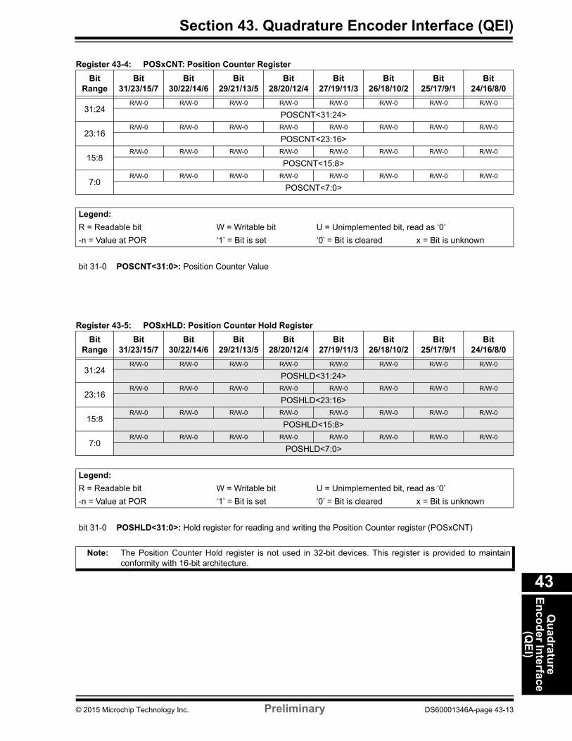
bit 31-0 POSHLD<31:0>: Hold register for reading and writing the Position Counter register (POSxCNT)
Note: The Position Counter Hold register is not used in 32-bit devices. This register is provided to maintain conformity with 16-bit architecture.
Register 43-4: POSxCNT: Position Counter Register
Bit Range
Bit31/23/15/7
Bit30/22/14/6
Bit29/21/13/5
Bit28/20/12/4
Bit27/19/11/3
Bit26/18/10/2
Bit25/17/9/1
Bit24/16/8/0
31:24R/W-0 R/W-0 R/W-0 R/W-0 R/W-0 R/W-0 R/W-0 R/W-0
POSCNT<31:24>
23:16R/W-0 R/W-0 R/W-0 R/W-0 R/W-0 R/W-0 R/W-0 R/W-0
POSCNT<23:16>
15:8R/W-0 R/W-0 R/W-0 R/W-0 R/W-0 R/W-0 R/W-0 R/W-0
POSCNT<15:8>
7:0R/W-0 R/W-0 R/W-0 R/W-0 R/W-0 R/W-0 R/W-0 R/W-0
POSCNT<7:0>
Legend:
R = Readable bit W = Writable bit U = Unimplemented bit, read as ‘0’
-n = Value at POR ‘1’ = Bit is set ‘0’ = Bit is cleared x = Bit is unknown
bit 31-0 POSCNT<31:0>: Position Counter Value
© 2015 Microchip Technology Inc. Preliminary DS60001346A-page 43-13
PIC32 Family Reference Manual
Register 43-7: VELxHLD: Velocity Counter Hold Register
Bit Range
Bit31/23/15/7
Bit30/22/14/6
Bit29/21/13/5
Bit28/20/12/4
Bit27/19/11/3
Bit26/18/10/2
Bit25/17/9/1
Bit24/16/8/0
31:24R/W-0 R/W-0 R/W-0 R/W-0 R/W-0 R/W-0 R/W-0 R/W-0
VELHLD<31:24>
23:16R/W-0 R/W-0 R/W-0 R/W-0 R/W-0 R/W-0 R/W-0 R/W-0
VELHLD<23:16>
15:8R/W-0 R/W-0 R/W-0 R/W-0 R/W-0 R/W-0 R/W-0 R/W-0
VELHLD<15:8>
7:0R/W-0 R/W-0 R/W-0 R/W-0 R/W-0 R/W-0 R/W-0 R/W-0
VELHLD<7:0>
Legend:
R = Readable bit W = Writable bit U = Unimplemented bit, read as ‘0’
-n = Value at POR ‘1’ = Bit is set ‘0’ = Bit is cleared x = Bit is unknown
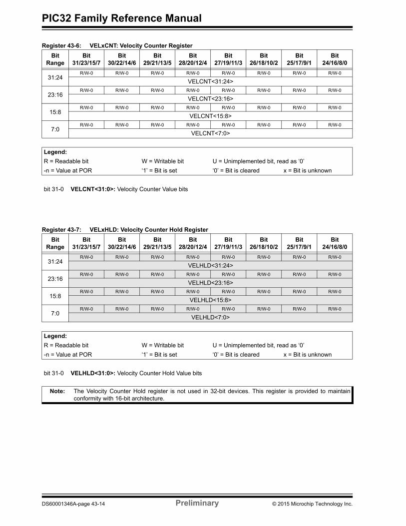
bit 31-0 VELHLD<31:0>: Velocity Counter Hold Value bits
Note: The Velocity Counter Hold register is not used in 32-bit devices. This register is provided to maintain conformity with 16-bit architecture.
Register 43-6: VELxCNT: Velocity Counter Register
Bit Range
Bit31/23/15/7
Bit30/22/14/6
Bit29/21/13/5
Bit28/20/12/4
Bit27/19/11/3
Bit26/18/10/2
Bit25/17/9/1
Bit24/16/8/0
31:24R/W-0 R/W-0 R/W-0 R/W-0 R/W-0 R/W-0 R/W-0 R/W-0
VELCNT<31:24>
23:16R/W-0 R/W-0 R/W-0 R/W-0 R/W-0 R/W-0 R/W-0 R/W-0
VELCNT<23:16>
15:8R/W-0 R/W-0 R/W-0 R/W-0 R/W-0 R/W-0 R/W-0 R/W-0
VELCNT<15:8>
7:0R/W-0 R/W-0 R/W-0 R/W-0 R/W-0 R/W-0 R/W-0 R/W-0
VELCNT<7:0>
Legend:
R = Readable bit W = Writable bit U = Unimplemented bit, read as ‘0’
-n = Value at POR ‘1’ = Bit is set ‘0’ = Bit is cleared x = Bit is unknown
bit 31-0 VELCNT<31:0>: Velocity Counter Value bits
DS60001346A-page 43-14 Preliminary © 2015 Microchip Technology Inc.
Section 43. Quadrature Encoder Interface (QEI)Q
uad
rature
En
cod
er Interface
(QE
I)
43
Register 43-9: INDXxHLD: Index Counter Hold Register
Bit Range
Bit31/23/15/7
Bit30/22/14/6
Bit29/21/13/5
Bit28/20/12/4
Bit27/19/11/3
Bit26/18/10/2
Bit25/17/9/1
Bit24/16/8/0
31:24R/W-0 R/W-0 R/W-0 R/W-0 R/W-0 R/W-0 R/W-0 R/W-0
INDXHLD<31:24>
23:16R/W-0 R/W-0 R/W-0 R/W-0 R/W-0 R/W-0 R/W-0 R/W-0
INDXHLD<23:16>
15:8R/W-0 R/W-0 R/W-0 R/W-0 R/W-0 R/W-0 R/W-0 R/W-0
INDXHLD<15:8>
7:0R/W-0 R/W-0 R/W-0 R/W-0 R/W-0 R/W-0 R/W-0 R/W-0
INDXHLD<7:0>
Legend:
R = Readable bit W = Writable bit U = Unimplemented bit, read as ‘0’
-n = Value at POR ‘1’ = Bit is set ‘0’ = Bit is cleared x = Bit is unknown
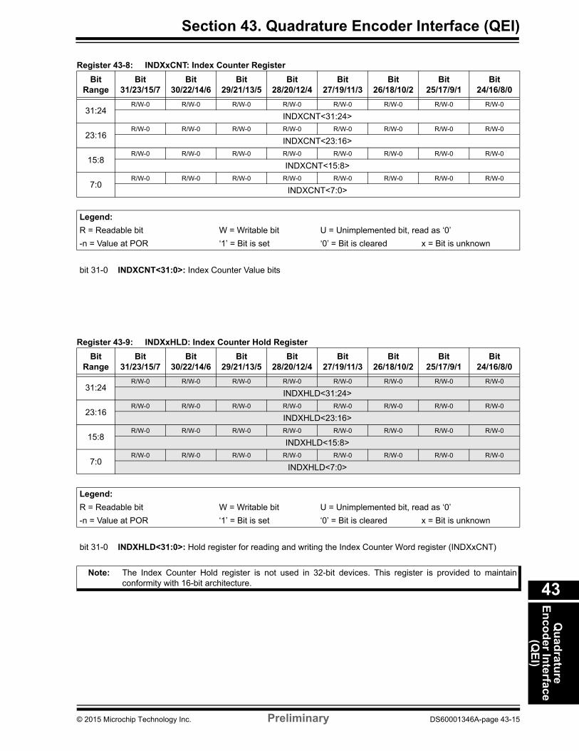
bit 31-0 INDXHLD<31:0>: Hold register for reading and writing the Index Counter Word register (INDXxCNT)
Note: The Index Counter Hold register is not used in 32-bit devices. This register is provided to maintain conformity with 16-bit architecture.
Register 43-8: INDXxCNT: Index Counter Register
Bit Range
Bit31/23/15/7
Bit30/22/14/6
Bit29/21/13/5
Bit28/20/12/4
Bit27/19/11/3
Bit26/18/10/2
Bit25/17/9/1
Bit24/16/8/0
31:24R/W-0 R/W-0 R/W-0 R/W-0 R/W-0 R/W-0 R/W-0 R/W-0
INDXCNT<31:24>
23:16R/W-0 R/W-0 R/W-0 R/W-0 R/W-0 R/W-0 R/W-0 R/W-0
INDXCNT<23:16>
15:8R/W-0 R/W-0 R/W-0 R/W-0 R/W-0 R/W-0 R/W-0 R/W-0
INDXCNT<15:8>
7:0R/W-0 R/W-0 R/W-0 R/W-0 R/W-0 R/W-0 R/W-0 R/W-0
INDXCNT<7:0>
Legend:
R = Readable bit W = Writable bit U = Unimplemented bit, read as ‘0’
-n = Value at POR ‘1’ = Bit is set ‘0’ = Bit is cleared x = Bit is unknown
bit 31-0 INDXCNT<31:0>: Index Counter Value bits
© 2015 Microchip Technology Inc. Preliminary DS60001346A-page 43-15
PIC32 Family Reference Manual
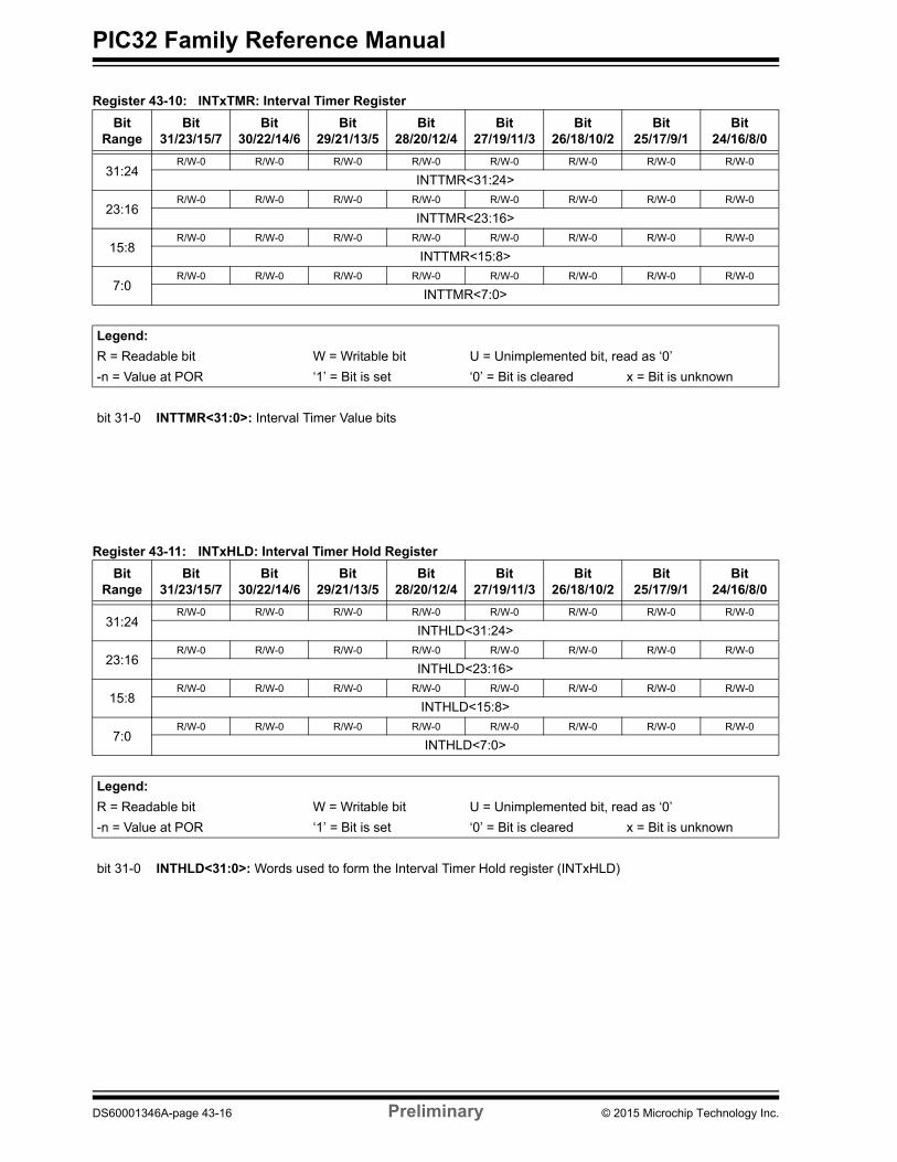
Register 43-11: INTxHLD: Interval Timer Hold Register
Bit Range
Bit31/23/15/7
Bit30/22/14/6
Bit29/21/13/5
Bit28/20/12/4
Bit27/19/11/3
Bit26/18/10/2
Bit25/17/9/1
Bit24/16/8/0
31:24R/W-0 R/W-0 R/W-0 R/W-0 R/W-0 R/W-0 R/W-0 R/W-0
INTHLD<31:24>
23:16R/W-0 R/W-0 R/W-0 R/W-0 R/W-0 R/W-0 R/W-0 R/W-0
INTHLD<23:16>
15:8R/W-0 R/W-0 R/W-0 R/W-0 R/W-0 R/W-0 R/W-0 R/W-0
INTHLD<15:8>
7:0R/W-0 R/W-0 R/W-0 R/W-0 R/W-0 R/W-0 R/W-0 R/W-0
INTHLD<7:0>
Legend:
R = Readable bit W = Writable bit U = Unimplemented bit, read as ‘0’
-n = Value at POR ‘1’ = Bit is set ‘0’ = Bit is cleared x = Bit is unknown
bit 31-0 INTHLD<31:0>: Words used to form the Interval Timer Hold register (INTxHLD)
Register 43-10: INTxTMR: Interval Timer Register
Bit Range
Bit31/23/15/7
Bit30/22/14/6
Bit29/21/13/5
Bit28/20/12/4
Bit27/19/11/3
Bit26/18/10/2
Bit25/17/9/1
Bit24/16/8/0
31:24R/W-0 R/W-0 R/W-0 R/W-0 R/W-0 R/W-0 R/W-0 R/W-0
INTTMR<31:24>
23:16R/W-0 R/W-0 R/W-0 R/W-0 R/W-0 R/W-0 R/W-0 R/W-0
INTTMR<23:16>
15:8R/W-0 R/W-0 R/W-0 R/W-0 R/W-0 R/W-0 R/W-0 R/W-0
INTTMR<15:8>
7:0R/W-0 R/W-0 R/W-0 R/W-0 R/W-0 R/W-0 R/W-0 R/W-0
INTTMR<7:0>
Legend:
R = Readable bit W = Writable bit U = Unimplemented bit, read as ‘0’
-n = Value at POR ‘1’ = Bit is set ‘0’ = Bit is cleared x = Bit is unknown
bit 31-0 INTTMR<31:0>: Interval Timer Value bits
DS60001346A-page 43-16 Preliminary © 2015 Microchip Technology Inc.
Section 43. Quadrature Encoder Interface (QEI)Q
uad
rature
En
cod
er Interface
(QE
I)
43
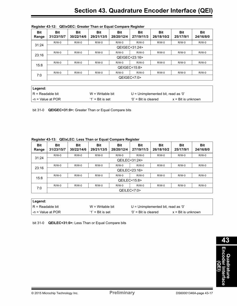
Register 43-13: QEIxLEC: Less Than or Equal Compare Register
Bit Range
Bit31/23/15/7
Bit30/22/14/6
Bit29/21/13/5
Bit28/20/12/4
Bit27/19/11/3
Bit26/18/10/2
Bit25/17/9/1
Bit24/16/8/0
31:24R/W-0 R/W-0 R/W-0 R/W-0 R/W-0 R/W-0 R/W-0 R/W-0
QEILEC<31:24>
23:16R/W-0 R/W-0 R/W-0 R/W-0 R/W-0 R/W-0 R/W-0 R/W-0
QEILEC<23:16>
15:8R/W-0 R/W-0 R/W-0 R/W-0 R/W-0 R/W-0 R/W-0 R/W-0
QEILEC<15:8>
7:0R/W-0 R/W-0 R/W-0 R/W-0 R/W-0 R/W-0 R/W-0 R/W-0
QEILEC<7:0>
Legend:
R = Readable bit W = Writable bit U = Unimplemented bit, read as ‘0’
-n = Value at POR ‘1’ = Bit is set ‘0’ = Bit is cleared x = Bit is unknown
bit 31-0 QEILEC<31:0>: Less Than or Equal Compare bits
Register 43-12: QEIxGEC: Greater Than or Equal Compare Register
Bit Range
Bit31/23/15/7
Bit30/22/14/6
Bit29/21/13/5
Bit28/20/12/4
Bit27/19/11/3
Bit26/18/10/2
Bit25/17/9/1
Bit24/16/8/0
31:24R/W-0 R/W-0 R/W-0 R/W-0 R/W-0 R/W-0 R/W-0 R/W-0
QEIGEC<31:24>
23:16R/W-0 R/W-0 R/W-0 R/W-0 R/W-0 R/W-0 R/W-0 R/W-0
QEIGEC<23:16>
15:8R/W-0 R/W-0 R/W-0 R/W-0 R/W-0 R/W-0 R/W-0 R/W-0
QEIGEC<15:8>
7:0R/W-0 R/W-0 R/W-0 R/W-0 R/W-0 R/W-0 R/W-0 R/W-0
QEIGEC<7:0>
Legend:
R = Readable bit W = Writable bit U = Unimplemented bit, read as ‘0’
-n = Value at POR ‘1’ = Bit is set ‘0’ = Bit is cleared x = Bit is unknown
bit 31-0 QEIGEC<31:0>: Greater Than or Equal Compare bits
© 2015 Microchip Technology Inc. Preliminary DS60001346A-page 43-17
PIC32 Family Reference Manual
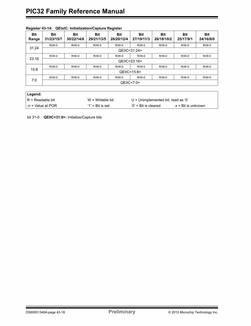
Register 43-14: QEIxIC: Initialization/Capture Register
Bit Range
Bit31/23/15/7
Bit30/22/14/6
Bit29/21/13/5
Bit28/20/12/4
Bit27/19/11/3
Bit26/18/10/2
Bit25/17/9/1
Bit24/16/8/0
31:24R/W-0 R/W-0 R/W-0 R/W-0 R/W-0 R/W-0 R/W-0 R/W-0
QEIIC<31:24>
23:16R/W-0 R/W-0 R/W-0 R/W-0 R/W-0 R/W-0 R/W-0 R/W-0
QEIIC<23:16>
15:8R/W-0 R/W-0 R/W-0 R/W-0 R/W-0 R/W-0 R/W-0 R/W-0
QEIIC<15:8>
7:0R/W-0 R/W-0 R/W-0 R/W-0 R/W-0 R/W-0 R/W-0 R/W-0
QEIIC<7:0>
Legend:
R = Readable bit W = Writable bit U = Unimplemented bit, read as ‘0’
-n = Value at POR ‘1’ = Bit is set ‘0’ = Bit is cleared x = Bit is unknown
bit 31-0 QEIIC<31:0>: Initialize/Capture bits
DS60001346A-page 43-18 Preliminary © 2015 Microchip Technology Inc.
Section 43. Quadrature Encoder Interface (QEI)Q
uad
rature
En
cod
er Interface
(QE
I)
43
43.3 MODULE DESCRIPTION
43.3.1 Position Counter
The position counter is 32 bits wide and is contained in the POSxCNT register. The counter counts the number of pulses generated by an encoder.
If the POSOVIEN bit (QEIxSTAT<8>) is set, and the position counter rolls over from 0x7FFFFFFF to 0x80000000, or from 0x80000000 to 0x7FFFFFFF, an interrupt will be generated.
The operating mode of the position counter is controlled by the CCM<1:0> bits (QEIxCON<1:0>). The position counter supports the following operating modes:
• Quadrature Count Mode• External Count with External Up/Down Mode• External Count with External Gate Mode• Internal Timer with External Gate Mode
43.3.1.1 QUADRATURE COUNT MODE
In this mode, the QEA/EXTCNT and QEB/DIR/GATE inputs are decoded to generate count pulses and direction information to control the POSxCNT and VELxCNT registers. The INDXxCNT register counts when a valid edge is detected on INDX input. Figure 43-1 illustrates the timing diagram of the Quadrature Count mode operation.
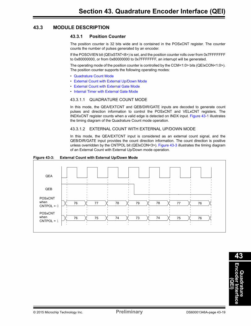
43.3.1.2 EXTERNAL COUNT WITH EXTERNAL UP/DOWN MODE
In this mode, the QEA/EXTCNT input is considered as an external count signal, and the QEB/DIR/GATE input provides the count direction information. The count direction is positive unless overridden by the CNTPOL bit (QEIxCON<3>). Figure 43-3 illustrates the timing diagram of an External Count with External Up/Down mode operation.
Figure 43-3: External Count with External Up/Down Mode
QEA
QEB
POSxCNT
CNTPOL = 0 when
POSxCNT
CNTPOL = 1 when
76 77 78 79 78 77 76
76 75 74 73 74 75 76
© 2015 Microchip Technology Inc. Preliminary DS60001346A-page 43-19
PIC32 Family Reference Manual
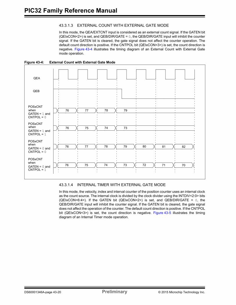
43.3.1.3 EXTERNAL COUNT WITH EXTERNAL GATE MODE
In this mode, the QEA/EXTCNT input is considered as an external count signal. If the GATEN bit (QEIxCON<2>) is set, and QEB/DIR/GATE = 0, the QEB/DIR/GATE input will inhibit the counter signal. If the GATEN bit is cleared, the gate signal does not affect the counter operation. The default count direction is positive. If the CNTPOL bit (QEIxCON<3>) is set, the count direction is negative. Figure 43-4 illustrates the timing diagram of an External Count with External Gate mode operation.
Figure 43-4: External Count with External Gate Mode
QEA
QEB
POSxCNT
GATEN = 1 andCNTPOL = 0 when
POSxCNT
GATEN = 1 andCNTPOL = 1
when
POSxCNT
GATEN = 0 andCNTPOL = 0
when
POSxCNT
GATEN = 0 andCNTPOL = 1
when
76 77 78 79 80 81 82
76 75 74 73 72 71 70
76 77 78 79
76 75 74 73
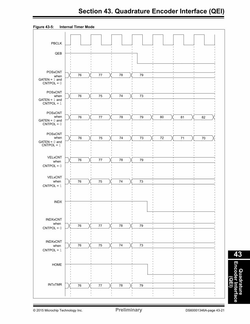
43.3.1.4 INTERNAL TIMER WITH EXTERNAL GATE MODE
In this mode, the velocity, index and interval counter of the position counter uses an internal clock as the count source. The internal clock is divided by the clock divider using the INTDIV<2:0> bits (QEIxCON<6:4>). If the GATEN bit (QEIxCON<2>) is set, and QEB/DIR/GATE = 0, the QEB/DIR/GATE input will inhibit the counter signal. If the GATEN bit is cleared, the gate signal does not affect the operation of the counter. The default count direction is positive. If the CNTPOL bit (QEIxCON<3>) is set, the count direction is negative. Figure 43-5 illustrates the timing diagram of an Internal Timer mode operation.
DS60001346A-page 43-20 Preliminary © 2015 Microchip Technology Inc.
Section 43. Quadrature Encoder Interface (QEI)Q
uad
rature
En
cod
er Interface
(QE
I)
43
Figure 43-5: Internal Timer Mode
QEB
PBCLK
POSxCNT
GATEN = 1 andCNTPOL = 0
when
POSxCNT
GATEN = 1 andCNTPOL = 1
when
POSxCNT
GATEN = 0 andCNTPOL = 0
when
POSxCNT
GATEN = 0 andCNTPOL = 1
when
VELxCNT
INDX
HOME
INTxTMR
when CNTPOL = 0
VELxCNTwhen
CNTPOL = 1
INDXxCNTwhen
CNTPOL = 0
INDXxCNTwhen
CNTPOL = 1
76 77 78 79
76 77 78 79
76 75 74 73
76 75 74 73
76 77 78 79
76 75 74 73
76 77 78 79
76 77 78 79 80 81 82
76 75 74 73 72 71 70
© 2015 Microchip Technology Inc. Preliminary DS60001346A-page 43-21
PIC32 Family Reference Manual
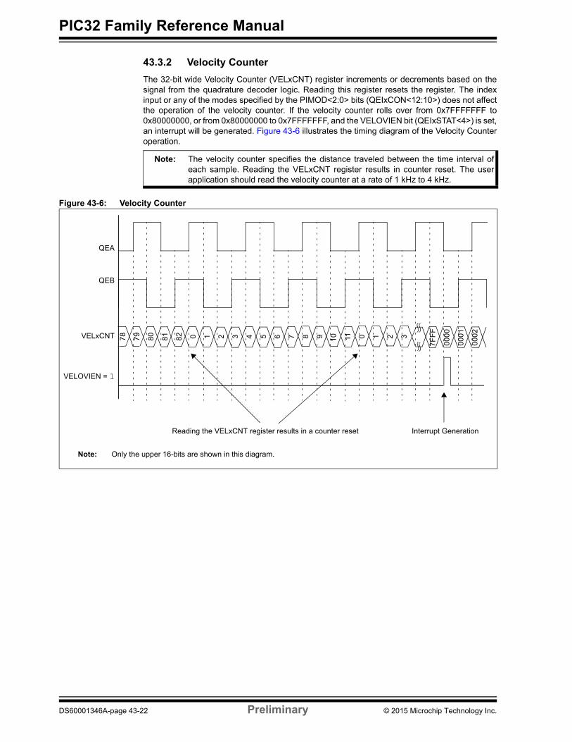
43.3.2 Velocity Counter
The 32-bit wide Velocity Counter (VELxCNT) register increments or decrements based on the signal from the quadrature decoder logic. Reading this register resets the register. The index input or any of the modes specified by the PIMOD<2:0> bits (QEIxCON<12:10>) does not affect the operation of the velocity counter. If the velocity counter rolls over from 0x7FFFFFFF to 0x80000000, or from 0x80000000 to 0x7FFFFFFF, and the VELOVIEN bit (QEIxSTAT<4>) is set, an interrupt will be generated. Figure 43-6 illustrates the timing diagram of the Velocity Counter operation.
Note: The velocity counter specifies the distance traveled between the time interval of each sample. Reading the VELxCNT register results in counter reset. The user application should read the velocity counter at a rate of 1 kHz to 4 kHz.
Figure 43-6: Velocity Counter
QEA
QEB
VELxCNT
VELOVIEN = 1
78
Interrupt GenerationReading the VELxCNT register results in a counter reset
79 80 81 82 0 1 2 3 4 5 6 7 9 11 0 1 2 3
7FF
F
0001
0002
108
0000
Note: Only the upper 16-bits are shown in this diagram.
DS60001346A-page 43-22 Preliminary © 2015 Microchip Technology Inc.
Section 43. Quadrature Encoder Interface (QEI)Q
uad
rature
En
cod
er Interface
(QE
I)
43
43.3.3 Index Counter
The 32-bit wide Index Counter (INDXxCNT) register counts index events. It is incremented or decremented based on the direction output of the quadrature logic decoder (see Figure 43-2). For more information, refer to 43.3.7 “Index Event”.
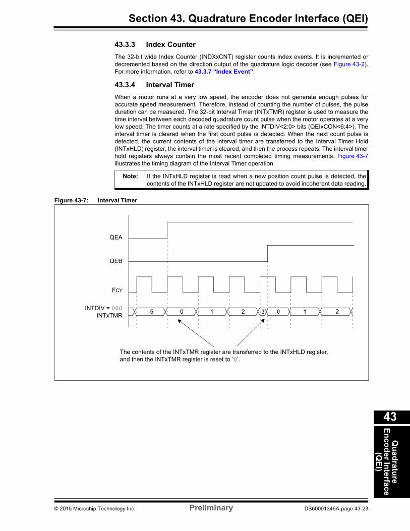
43.3.4 Interval Timer
When a motor runs at a very low speed, the encoder does not generate enough pulses for accurate speed measurement. Therefore, instead of counting the number of pulses, the pulse duration can be measured. The 32-bit Interval Timer (INTxTMR) register is used to measure the time interval between each decoded quadrature count pulse when the motor operates at a very low speed. The timer counts at a rate specified by the INTDIV<2:0> bits (QEIxCON<6:4>). The interval timer is cleared when the first count pulse is detected. When the next count pulse is detected, the current contents of the interval timer are transferred to the Interval Timer Hold (INTxHLD) register, the interval timer is cleared, and then the process repeats. The interval timer hold registers always contain the most recent completed timing measurements. Figure 43-7 illustrates the timing diagram of the Interval Timer operation.
Note: If the INTxHLD register is read when a new position count pulse is detected, the contents of the INTxHLD register are not updated to avoid incoherent data reading.
Figure 43-7: Interval Timer
5 0 1 2 1
QEA
QEB
FCY
INTDIV = 000INTxTMR
The contents of the INTxTMR register are transferred to the INTxHLD register,
23 0
and then the INTxTMR register is reset to ‘0’.
© 2015 Microchip Technology Inc. Preliminary DS60001346A-page 43-23
PIC32 Family Reference Manual
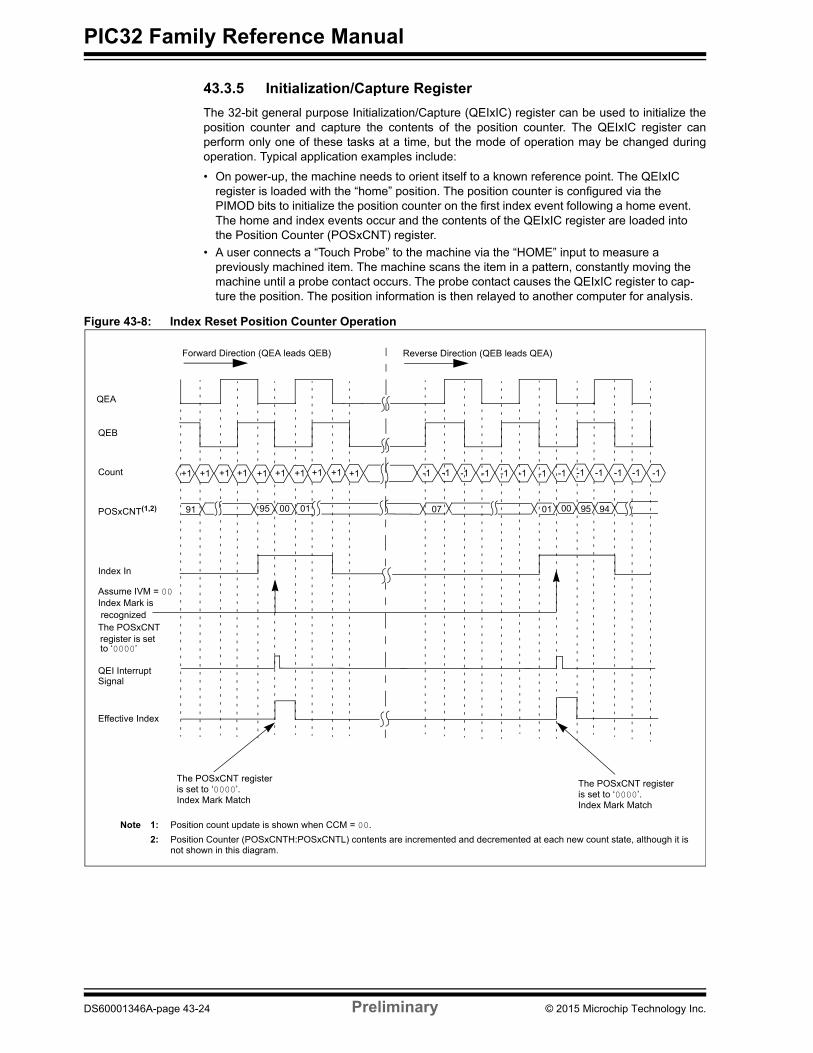
43.3.5 Initialization/Capture Register
The 32-bit general purpose Initialization/Capture (QEIxIC) register can be used to initialize the position counter and capture the contents of the position counter. The QEIxIC register can perform only one of these tasks at a time, but the mode of operation may be changed during operation. Typical application examples include:
• On power-up, the machine needs to orient itself to a known reference point. The QEIxIC register is loaded with the “home” position. The position counter is configured via the PIMOD bits to initialize the position counter on the first index event following a home event. The home and index events occur and the contents of the QEIxIC register are loaded into the Position Counter (POSxCNT) register.
• A user connects a “Touch Probe” to the machine via the “HOME” input to measure a previously machined item. The machine scans the item in a pattern, constantly moving the machine until a probe contact occurs. The probe contact causes the QEIxIC register to cap-ture the position. The position information is then relayed to another computer for analysis.
Figure 43-8: Index Reset Position Counter Operation
+1+1 +1 +1 +1 +1 +1 -1 -1 -1 -1 -1 -1 -1 -1 -1 -1 -1 -1
Note 1: Position count update is shown when CCM = 00.
2: Position Counter (POSxCNTH:POSxCNTL) contents are incremented and decremented at each new count state, although it is not shown in this diagram.
91
QEA
Count
POSxCNT(1,2)
Index Mark is
+1
95 00 01 9507
QEB
Forward Direction (QEA leads QEB) Reverse Direction (QEB leads QEA)
The POSxCNT
Index In
Assume IVM = 00
Effective Index
01 00 94
Index Mark Match
The POSxCNT registeris set to ‘0000’.
QEI Interrupt
-1+1
recognized
to ‘0000’set
Index Mark Match
The POSxCNT registeris set to ‘0000’.
register is
+1
Signal
DS60001346A-page 43-24 Preliminary © 2015 Microchip Technology Inc.
Section 43. Quadrature Encoder Interface (QEI)Q
uad
rature
En
cod
er Interface
(QE
I)
43
43.3.6 Position Comparator
The QEIxLEC and QEIxGEC registers and the associated comparator provide the ability to compare the contents of the Position Counter (POSxCNT) register to a specified value. The comparator provides two outputs: equality detect, and less than or greater than detect. The comparator equality output can be enabled to generate interrupts via the PCLEQIEN bit (QEIxSTAT<10>). The less than or equal, or greater than or equal output can be output on a device pin. The selection is made by setting the OUTFNC<1:0> bits (QEIxIOC<10:9>). The comparator output can be used to detect an illegal move operation by an end user and the comparator output can be connected to appropriate external circuitry to prevent the illegal move.
Sometimes, the potential for costly damage to a part, or a machine due to an operator, programming, or a machine failure is too much to accept. The QEIxLEC and QEIxGEC registers can be configured to define a bounds of travel beyond which a Fault is generated. The values in these registers are continually compared to the position counter. The comparator output can be directed to a device pin. This Fault detected signal can be used to shut down the machine operation to prevent damage or injury.
The comparator can also be used to reset the position counter when a match is detected.
Figure 43-8, on the previous page, illustrates the index reset position counter operation.
43.3.7 Index Event
The IMV<1:0> bits (QEIxCON<9:8>) specify the state of the QEA and QEB input signals required to acknowledge an index event. An index event is accepted when an index pulse occurs while the value of the QEA and QEB inputs match the condition set in the IMV<1:0> bits. This prevents further index events from being accepted until the index input signal is deasserted, and ensures that only one index event occurs for each index input pulse. Figure 43-8, on the previous page, illustrates the index reset position counter operation.
43.3.8 Position Counter Initialization Modes
By using the PIMOD<2:0> bits (QEIxCON<12:10>), the user application can specify how the position counter is initialized during the module operation.
• Mode 0 - The position counter is unaffected by the index input• Mode 1 - The position counter is cleared whenever an index input event is detected.• Mode 2 - The position counter is initialized with the contents of the QEIxIC register on the
next detected index input event. When the index event occurs, the PIMOD<2:0> bits are cleared, and then the counter operates in Mode 0.
• Mode 3 - The position counter is initialized with the contents of the QEIxIC register on the next detected index input event following the assertion of the home input. When an index event occurs following the home event, the PIMOD<2:0> bits are cleared, and then the counter operates in Mode 0.
• Mode 4 - The position counter is initialized with the contents of the QEIxIC register on the second detected index input event following the assertion of the home input. When the second index event occurs following the home event, the PIMOD<2:0> bits are cleared, and then the counter operates in Mode 0.
• Mode 5 - The position counter is cleared when the position counter value equals the QEIxGEC register value
• Mode 6 - The position counter is loaded with the contents of the QEIxLEC register when the position counter value equals the QEIxGEC register value and a count up pulse is detected. The counter is loaded with the contents of the QEIxGEC register when the position counter value equals the QEIxLEC register value and a count down pulse is detected.
• Mode 7 - Same as mode 6, with the additional feature of the position counter being cleared whenever an index input event is detected
© 2015 Microchip Technology Inc. Preliminary DS60001346A-page 43-25
PIC32 Family Reference Manual
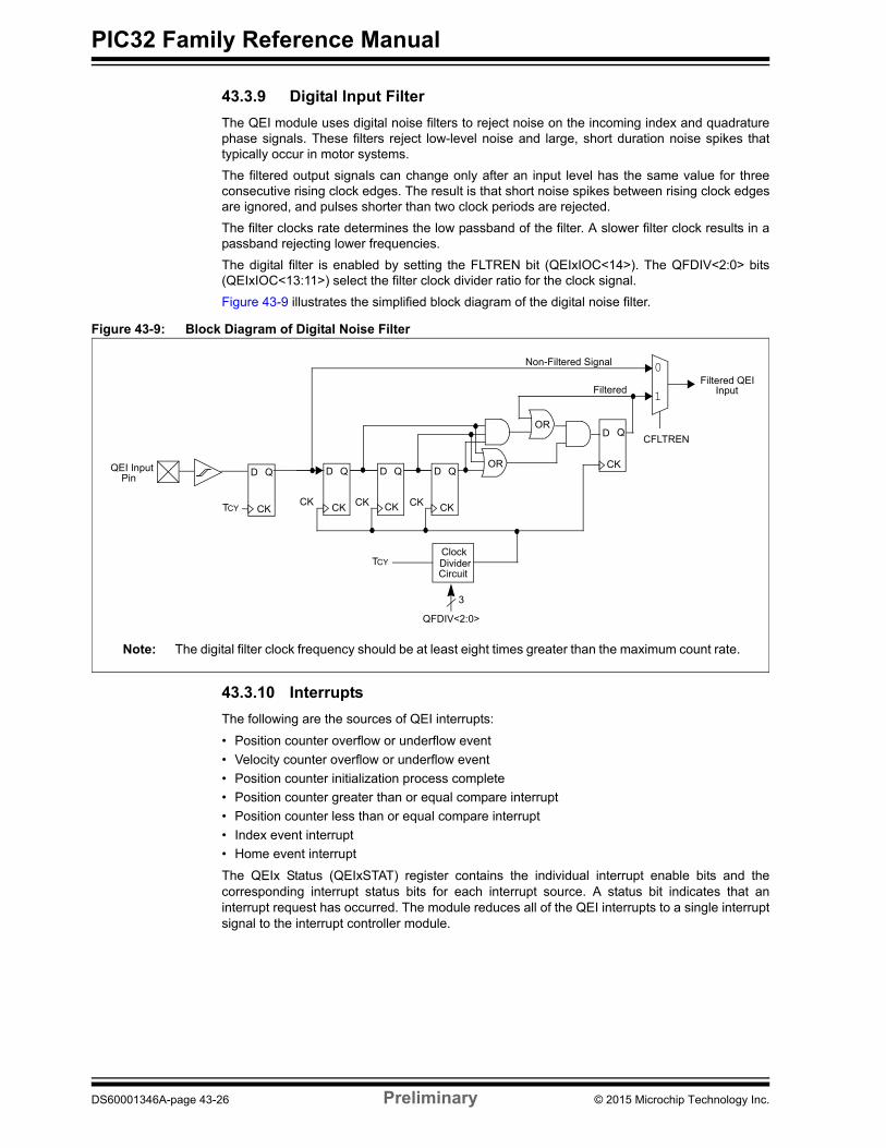
43.3.9 Digital Input Filter
The QEI module uses digital noise filters to reject noise on the incoming index and quadrature phase signals. These filters reject low-level noise and large, short duration noise spikes that typically occur in motor systems.
The filtered output signals can change only after an input level has the same value for three consecutive rising clock edges. The result is that short noise spikes between rising clock edges are ignored, and pulses shorter than two clock periods are rejected.
The filter clocks rate determines the low passband of the filter. A slower filter clock results in a passband rejecting lower frequencies.
The digital filter is enabled by setting the FLTREN bit (QEIxIOC<14>). The QFDIV<2:0> bits (QEIxIOC<13:11>) select the filter clock divider ratio for the clock signal.
Figure 43-9 illustrates the simplified block diagram of the digital noise filter.
Figure 43-9: Block Diagram of Digital Noise Filter
QEI Input D Q
TCY
Filtered QEI
CK
Input
Pin
D Q
D Q D Q D Q
Filtered
ClockDividerCircuit
Non-Filtered Signal 0
1
CK
3
CKCK CK CKCKCK
QFDIV<2:0>
CFLTREN
TCY
OR
OR
Note: The digital filter clock frequency should be at least eight times greater than the maximum count rate.
43.3.10 Interrupts
The following are the sources of QEI interrupts:
• Position counter overflow or underflow event
• Velocity counter overflow or underflow event
• Position counter initialization process complete
• Position counter greater than or equal compare interrupt
• Position counter less than or equal compare interrupt
• Index event interrupt
• Home event interrupt
The QEIx Status (QEIxSTAT) register contains the individual interrupt enable bits and the corresponding interrupt status bits for each interrupt source. A status bit indicates that an interrupt request has occurred. The module reduces all of the QEI interrupts to a single interrupt signal to the interrupt controller module.
DS60001346A-page 43-26 Preliminary © 2015 Microchip Technology Inc.
Section 43. Quadrature Encoder Interface (QEI)Q
uad
rature
En
cod
er Interface
(QE
I)
43
43.4 QEI OPERATION IN POWER-SAVING MODES
43.4.1 Sleep Mode
When the device enters Sleep mode, QEI operations cease. The POSxCNT register stops at the current value. The QEI does not respond to active signals on the QEA, QEB or INDX pins. The QEIxCON register remains unchanged.
43.4.2 Idle Mode
When the device enters Idle mode, the QEISIDL bit (QEIxCON<13>) determines whether the QEI module stops in Idle mode or continues to operate in Idle mode.
If QEISIDL = 1, the QEI module enters into a power-saving mode and performs the same functions as in Sleep mode. If QEISIDL = 0, the module does not enter into a power-saving mode and continues operation in Idle mode.
43.5 EFFECTS OF A RESET
A Reset forces module registers to their initial Reset state.
© 2015 Microchip Technology Inc. Preliminary DS60001346A-page 43-27
PIC32 Family Reference Manual
43.6 RELATED APPLICATION NOTES
This section lists application notes that are related to this section of the manual. These application notes may not be written specifically for the PIC32 device family, but the concepts are pertinent and could be used with modification and possible limitations. The current application notes related to the Quadrature Encoder Interface (QEI) module are:
Title Application Note #
No applications notes at this time N/A
Note: Please visit the Microchip web site (www.microchip.com) for additional application notes and code examples for the PIC32 family of devices.
DS60001346A-page 43-28 Preliminary © 2015 Microchip Technology Inc.
Section 43. Quadrature Encoder Interface (QEI)Q
uad
rature
En
cod
er Interface
(QE
I)
43
43.7 REVISION HISTORY
Revision A (June 2015)
This is the initial released version of this document.
© 2015 Microchip Technology Inc. Preliminary DS60001346A-page 43-29
PIC32 Family Reference Manual
NOTES:
DS60001346A-page 43-30 Preliminary © 2015 Microchip Technology Inc.
Note the following details of the code protection feature on Microchip devices:
• Microchip products meet the specification contained in their particular Microchip Data Sheet.
• Microchip believes that its family of products is one of the most secure families of its kind on the market today, when used in the intended manner and under normal conditions.
• There are dishonest and possibly illegal methods used to breach the code protection feature. All of these methods, to our knowledge, require using the Microchip products in a manner outside the operating specifications contained in Microchip’s Data Sheets. Most likely, the person doing so is engaged in theft of intellectual property.
• Microchip is willing to work with the customer who is concerned about the integrity of their code.
• Neither Microchip nor any other semiconductor manufacturer can guarantee the security of their code. Code protection does not mean that we are guaranteeing the product as “unbreakable.”
Code protection is constantly evolving. We at Microchip are committed to continuously improving the code protection features of our products. Attempts to break Microchip’s code protection feature may be a violation of the Digital Millennium Copyright Act. If such acts allow unauthorized access to your software or other copyrighted work, you may have a right to sue for relief under that Act.
Information contained in this publication regarding device applications and the like is provided only for your convenience and may be superseded by updates. It is your responsibility to ensure that your application meets with your specifications. MICROCHIP MAKES NO REPRESENTATIONS OR WARRANTIES OF ANY KIND WHETHER EXPRESS OR IMPLIED, WRITTEN OR ORAL, STATUTORY OR OTHERWISE, RELATED TO THE INFORMATION, INCLUDING BUT NOT LIMITED TO ITS CONDITION, QUALITY, PERFORMANCE, MERCHANTABILITY OR FITNESS FOR PURPOSE. Microchip disclaims all liability arising from this information and its use. Use of Microchip devices in life support and/or safety applications is entirely at the buyer’s risk, and the buyer agrees to defend, indemnify and hold harmless Microchip from any and all damages, claims, suits, or expenses resulting from such use. No licenses are conveyed, implicitly or otherwise, under any Microchip intellectual property rights.
2015 Microchip Technology Inc. Prelimin
QUALITY MANAGEMENT SYSTEM CERTIFIED BY DNV
== ISO/TS 16949 ==
Trademarks
The Microchip name and logo, the Microchip logo, dsPIC, FlashFlex, flexPWR, JukeBlox, KEELOQ, KEELOQ logo, Kleer, LANCheck, MediaLB, MOST, MOST logo, MPLAB, OptoLyzer, PIC, PICSTART, PIC32 logo, RightTouch, SpyNIC, SST, SST Logo, SuperFlash and UNI/O are registered trademarks of Microchip Technology Incorporated in the U.S.A. and other countries.
The Embedded Control Solutions Company and mTouch are registered trademarks of Microchip Technology Incorporated in the U.S.A.
Analog-for-the-Digital Age, BodyCom, chipKIT, chipKIT logo, CodeGuard, dsPICDEM, dsPICDEM.net, ECAN, In-Circuit Serial Programming, ICSP, Inter-Chip Connectivity, KleerNet, KleerNet logo, MiWi, MPASM, MPF, MPLAB Certified logo, MPLIB, MPLINK, MultiTRAK, NetDetach, Omniscient Code Generation, PICDEM, PICDEM.net, PICkit, PICtail, RightTouch logo, REAL ICE, SQI, Serial Quad I/O, Total Endurance, TSHARC, USBCheck, VariSense, ViewSpan, WiperLock, Wireless DNA, and ZENA are trademarks of Microchip Technology Incorporated in the U.S.A. and other countries.
SQTP is a service mark of Microchip Technology Incorporated in the U.S.A.
Silicon Storage Technology is a registered trademark of Microchip Technology Inc. in other countries.
GestIC is a registered trademarks of Microchip Technology Germany II GmbH & Co. KG, a subsidiary of Microchip Technology Inc., in other countries.
All other trademarks mentioned herein are property of their respective companies.
© 2015, Microchip Technology Incorporated, Printed in the U.S.A., All Rights Reserved.
ISBN: 978-1-63277-454-5
ary DS60001346A-page 43 -31
Microchip received ISO/TS-16949:2009 certification for its worldwide headquarters, design and wafer fabrication facilities in Chandler and Tempe, Arizona; Gresham, Oregon and design centers in California and India. The Company’s quality system processes and procedures are for its PIC® MCUs and dsPIC® DSCs, KEELOQ® code hopping devices, Serial EEPROMs, microperipherals, nonvolatile memory and analog products. In addition, Microchip’s quality system for the design and manufacture of development systems is ISO 9001:2000 certified.

DS60001346A-page 43 -32 Preliminary 2015 Microchip Technology Inc.
AMERICASCorporate Office2355 West Chandler Blvd.Chandler, AZ 85224-6199Tel: 480-792-7200 Fax: 480-792-7277Technical Support: http://www.microchip.com/supportWeb Address: www.microchip.com
AtlantaDuluth, GA Tel: 678-957-9614 Fax: 678-957-1455
Austin, TXTel: 512-257-3370
BostonWestborough, MA Tel: 774-760-0087 Fax: 774-760-0088
ChicagoItasca, IL Tel: 630-285-0071 Fax: 630-285-0075
ClevelandIndependence, OH Tel: 216-447-0464 Fax: 216-447-0643
DallasAddison, TX Tel: 972-818-7423 Fax: 972-818-2924
DetroitNovi, MI Tel: 248-848-4000
Houston, TX Tel: 281-894-5983
IndianapolisNoblesville, IN Tel: 317-773-8323Fax: 317-773-5453
Los AngelesMission Viejo, CA Tel: 949-462-9523 Fax: 949-462-9608
New York, NY Tel: 631-435-6000
San Jose, CA Tel: 408-735-9110
Canada - TorontoTel: 905-673-0699 Fax: 905-673-6509
ASIA/PACIFICAsia Pacific OfficeSuites 3707-14, 37th FloorTower 6, The GatewayHarbour City, KowloonHong KongTel: 852-2943-5100Fax: 852-2401-3431
Australia - SydneyTel: 61-2-9868-6733Fax: 61-2-9868-6755
China - BeijingTel: 86-10-8569-7000 Fax: 86-10-8528-2104
China - ChengduTel: 86-28-8665-5511Fax: 86-28-8665-7889
China - ChongqingTel: 86-23-8980-9588Fax: 86-23-8980-9500
China - Dongguan
Tel: 86-769-8702-9880
China - HangzhouTel: 86-571-8792-8115 Fax: 86-571-8792-8116
China - Hong Kong SARTel: 852-2943-5100 Fax: 852-2401-3431
China - NanjingTel: 86-25-8473-2460Fax: 86-25-8473-2470
China - QingdaoTel: 86-532-8502-7355Fax: 86-532-8502-7205
China - ShanghaiTel: 86-21-5407-5533 Fax: 86-21-5407-5066
China - ShenyangTel: 86-24-2334-2829Fax: 86-24-2334-2393
China - ShenzhenTel: 86-755-8864-2200 Fax: 86-755-8203-1760
China - WuhanTel: 86-27-5980-5300Fax: 86-27-5980-5118
China - XianTel: 86-29-8833-7252Fax: 86-29-8833-7256
ASIA/PACIFICChina - XiamenTel: 86-592-2388138 Fax: 86-592-2388130
China - ZhuhaiTel: 86-756-3210040 Fax: 86-756-3210049
India - BangaloreTel: 91-80-3090-4444 Fax: 91-80-3090-4123
India - New DelhiTel: 91-11-4160-8631Fax: 91-11-4160-8632
India - PuneTel: 91-20-3019-1500
Japan - OsakaTel: 81-6-6152-7160 Fax: 81-6-6152-9310
Japan - TokyoTel: 81-3-6880- 3770 Fax: 81-3-6880-3771
Korea - DaeguTel: 82-53-744-4301Fax: 82-53-744-4302
Korea - SeoulTel: 82-2-554-7200Fax: 82-2-558-5932 or 82-2-558-5934
Malaysia - Kuala LumpurTel: 60-3-6201-9857Fax: 60-3-6201-9859
Malaysia - PenangTel: 60-4-227-8870Fax: 60-4-227-4068
Philippines - ManilaTel: 63-2-634-9065Fax: 63-2-634-9069
SingaporeTel: 65-6334-8870Fax: 65-6334-8850
Taiwan - Hsin ChuTel: 886-3-5778-366Fax: 886-3-5770-955
Taiwan - KaohsiungTel: 886-7-213-7828
Taiwan - TaipeiTel: 886-2-2508-8600 Fax: 886-2-2508-0102
Thailand - BangkokTel: 66-2-694-1351Fax: 66-2-694-1350
EUROPEAustria - WelsTel: 43-7242-2244-39Fax: 43-7242-2244-393Denmark - CopenhagenTel: 45-4450-2828 Fax: 45-4485-2829
France - ParisTel: 33-1-69-53-63-20 Fax: 33-1-69-30-90-79
Germany - DusseldorfTel: 49-2129-3766400
Germany - MunichTel: 49-89-627-144-0 Fax: 49-89-627-144-44
Germany - PforzheimTel: 49-7231-424750
Italy - Milan Tel: 39-0331-742611 Fax: 39-0331-466781
Italy - VeniceTel: 39-049-7625286
Netherlands - DrunenTel: 31-416-690399 Fax: 31-416-690340
Poland - WarsawTel: 48-22-3325737
Spain - MadridTel: 34-91-708-08-90Fax: 34-91-708-08-91
Sweden - StockholmTel: 46-8-5090-4654
UK - WokinghamTel: 44-118-921-5800Fax: 44-118-921-5820
Worldwide Sales and Service
01/27/15