Design and Installation Guidelines for Erosion...
18
1 | Page 2013 Geo Products, LLC Design and Installation Guidelines for Erosion Control Geo Products, LLC 8615 Golden Spike Lane Houston, TX 77086 Phone: 281.820.5493 Fax: 281.820.5499 www.geoproducts.org
Transcript of Design and Installation Guidelines for Erosion...
1 | P a g e 2013 Geo Products, LLC
Design and Installation Guidelines for Erosion Control
Geo Products, LLC 8615 Golden Spike Lane
Houston, TX 77086 Phone: 281.820.5493
Fax: 281.820.5499 www.geoproducts.org
2 | P a g e 2013 Geo Products, LLC
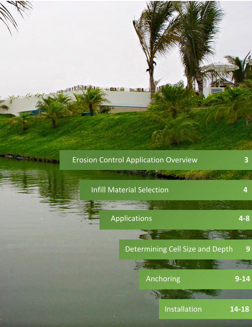
Applications 4-8
Determining Cell Size and Depth 9
Anchoring 9-14
Installation 14-18
Erosion Control Application Overview 3
Infill Material Selection 4
3 | P a g e 2013 Geo Products, LLC
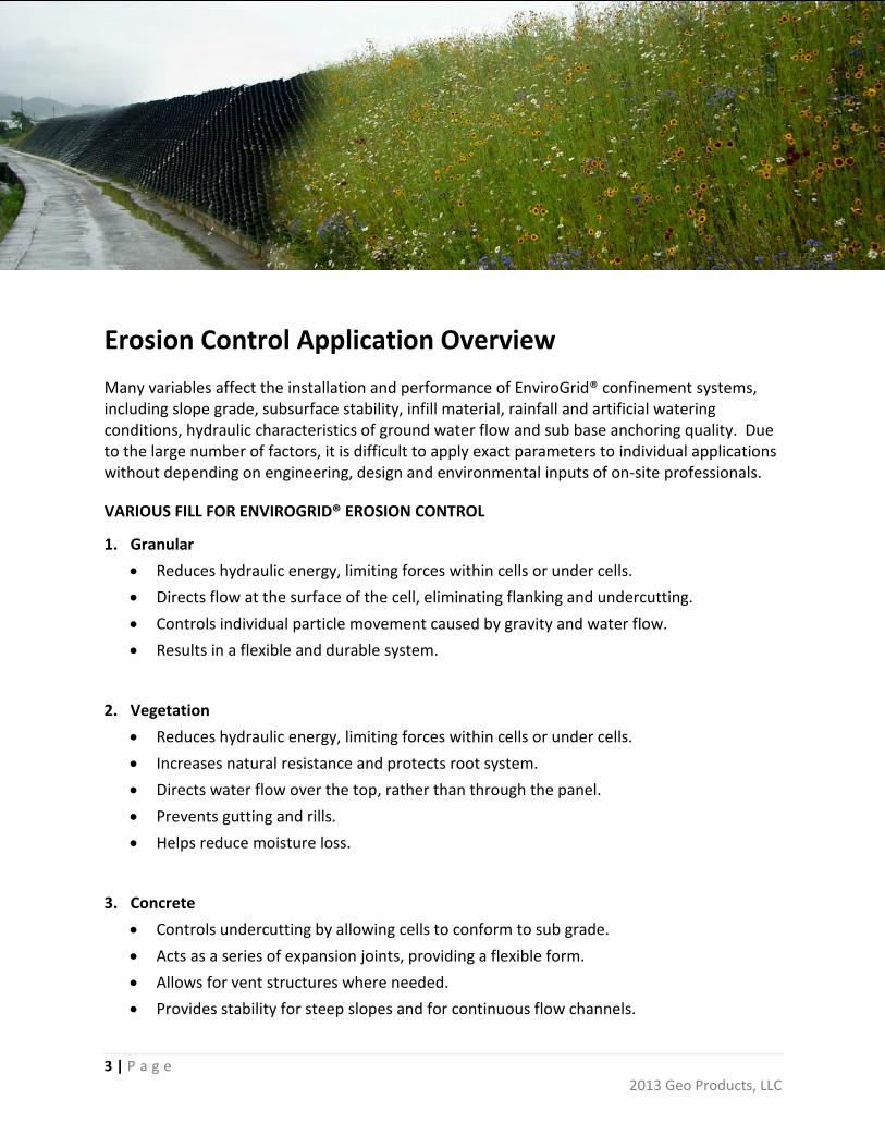
Erosion Control Application Overview Many variables affect the installation and performance of EnviroGrid® confinement systems, including slope grade, subsurface stability, infill material, rainfall and artificial watering conditions, hydraulic characteristics of ground water flow and sub base anchoring quality. Due to the large number of factors, it is difficult to apply exact parameters to individual applications without depending on engineering, design and environmental inputs of on-site professionals.
VARIOUS FILL FOR ENVIROGRID® EROSION CONTROL
1. Granular • Reduces hydraulic energy, limiting forces within cells or under cells. • Directs flow at the surface of the cell, eliminating flanking and undercutting. • Controls individual particle movement caused by gravity and water flow. • Results in a flexible and durable system.
2. Vegetation • Reduces hydraulic energy, limiting forces within cells or under cells. • Increases natural resistance and protects root system. • Directs water flow over the top, rather than through the panel. • Prevents gutting and rills. • Helps reduce moisture loss.
3. Concrete • Controls undercutting by allowing cells to conform to sub grade. • Acts as a series of expansion joints, providing a flexible form. • Allows for vent structures where needed. • Provides stability for steep slopes and for continuous flow channels.
4 | P a g e 2013 Geo Products, LLC
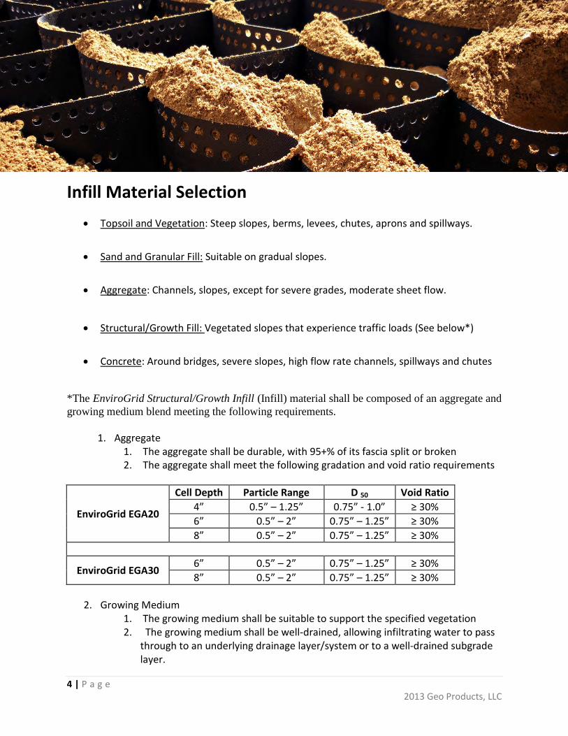
Infill Material Selection • Topsoil and Vegetation: Steep slopes, berms, levees, chutes, aprons and spillways.
• Sand and Granular Fill: Suitable on gradual slopes.
• Aggregate: Channels, slopes, except for severe grades, moderate sheet flow.
• Structural/Growth Fill: Vegetated slopes that experience traffic loads (See below*)
• Concrete: Around bridges, severe slopes, high flow rate channels, spillways and chutes
*The EnviroGrid Structural/Growth Infill (Infill) material shall be composed of an aggregate and growing medium blend meeting the following requirements.
1. Aggregate 1. The aggregate shall be durable, with 95+% of its fascia split or broken 2. The aggregate shall meet the following gradation and void ratio requirements
EnviroGrid EGA20
Cell Depth Particle Range D 50 Void Ratio 4” 0.5” – 1.25” 0.75” - 1.0” ≥ 30% 6” 0.5” – 2” 0.75” – 1.25” ≥ 30% 8” 0.5” – 2” 0.75” – 1.25” ≥ 30%
EnviroGrid EGA30 6” 0.5” – 2” 0.75” – 1.25” ≥ 30% 8” 0.5” – 2” 0.75” – 1.25” ≥ 30%
2. Growing Medium 1. The growing medium shall be suitable to support the specified vegetation 2. The growing medium shall be well-drained, allowing infiltrating water to pass
through to an underlying drainage layer/system or to a well-drained subgrade layer.
5 | P a g e 2013 Geo Products, LLC
3. The growing medium shall be screened to remove sticks, soil clods and other deleterious materials which prevent proper blending with the aggregate and placement with the EnviroGrid product.
3. Blended Aggregate and Growing Medium (Infill) 1. The Aggregate and Growing Medium shall be pre-blended to achieve a
homogenous mixture (Infill) prior to placement into the EnviroGrid. 2. The bulked (un-compacted) volume of Growing Medium shall be 95% - 100%
of the void volume within the compacted aggregate. 4. The Infill material shall be placed into the EnviroGrid material and compacted to a
minimum of 95% Standard Proctor Density or per the Engineer’s requirements. 1. Placement of the bulked, blended Infill should result in an ‘overfill’ of the
EnviroGrid product. Typically, a 0.5” – 0.75” overfill is needed for 4” deep EnviroGrid products. A 0.75” to 1.5” overfill is needed for the 6” and 8” material.
2. Compaction shall result in the Infill being level with or slightly above the cell walls of the EnviroGrid product.
3. Operation of compaction equipment directly on the cell walls of the EnviroGrid product is prohibitive.
Applications
SLOPES
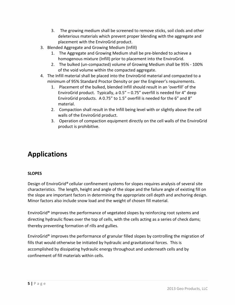
Design of EnviroGrid® cellular confinement systems for slopes requires analysis of several site characteristics. The length, height and angle of the slope and the failure angle of existing fill on the slope are important factors in determining the appropriate cell depth and anchoring design. Minor factors also include snow load and the weight of chosen fill material. EnviroGrid® improves the performance of vegetated slopes by reinforcing root systems and directing hydraulic flows over the top of cells, with the cells acting as a series of check dams; thereby preventing formation of rills and gullies.
EnviroGrid® improves the performance of granular filled slopes by controlling the migration of fills that would otherwise be initiated by hydraulic and gravitational forces. This is accomplished by dissipating hydraulic energy throughout and underneath cells and by confinement of fill materials within cells.

6 | P a g e 2013 Geo Products, LLC
CHANNELS
EnviroGrid® cellular confinement systems offer a large array of methods for solving difficult situations with channel bottoms and slopes where minimal to severe erosive forces are at work, with either intermittent or continuous flows.
Cellular confinement allows for the use of various types of infill, including soil with vegetation, aggregate, concrete or combination thereof, for unique and aesthetic applications.
Vegetative Soil Infilled Channel
Confined vegetative soil performs exceptionally well in applications with low to moderate flows. EnviroGrid® Cellular confinement enhances the performance of vegetation through reinforcing root zones and directing flows over the top cells; there by increasing the shear resistance of the fill and providing a finished site that is aesthetically superior when compared to conventional methods.
Soil infill with grass cover: • Peak flow velocity less than 6 m/s (20 fps) and duration of peak flow less than 24 hours. • Peak flow velocity less than 4.5 m/s (15 fps) and duration of peak flow less than 48
hours. • Channel side slopes above high water level

7 | P a g e 2013 Geo Products, LLC
Aggregate Infilled Channel
Aggregate performs well, allowing the use of different sizes for variances in flow velocities encountered from site to site. This provides an aesthetically pleasing and cost effective alternative to large rip rap or hard armoring by confining and improving the performance of smaller diameter, less costly aggregate.
Peak Flow Velocities with Stone Infill and recommended sizes:
•Graded Stone
<1 m/s (3.3 fps)
•38mm (1.5") median stone size 1-2 m/s
(3.3-6.6 fps)
•125mm (5") median stone size 2-3 m/s
(6.6-11.5 fps)
•STONE INFILL NOT RECOMMENDED
> 3 m/s (11.5 fps)
8 | P a g e 2013 Geo Products, LLC
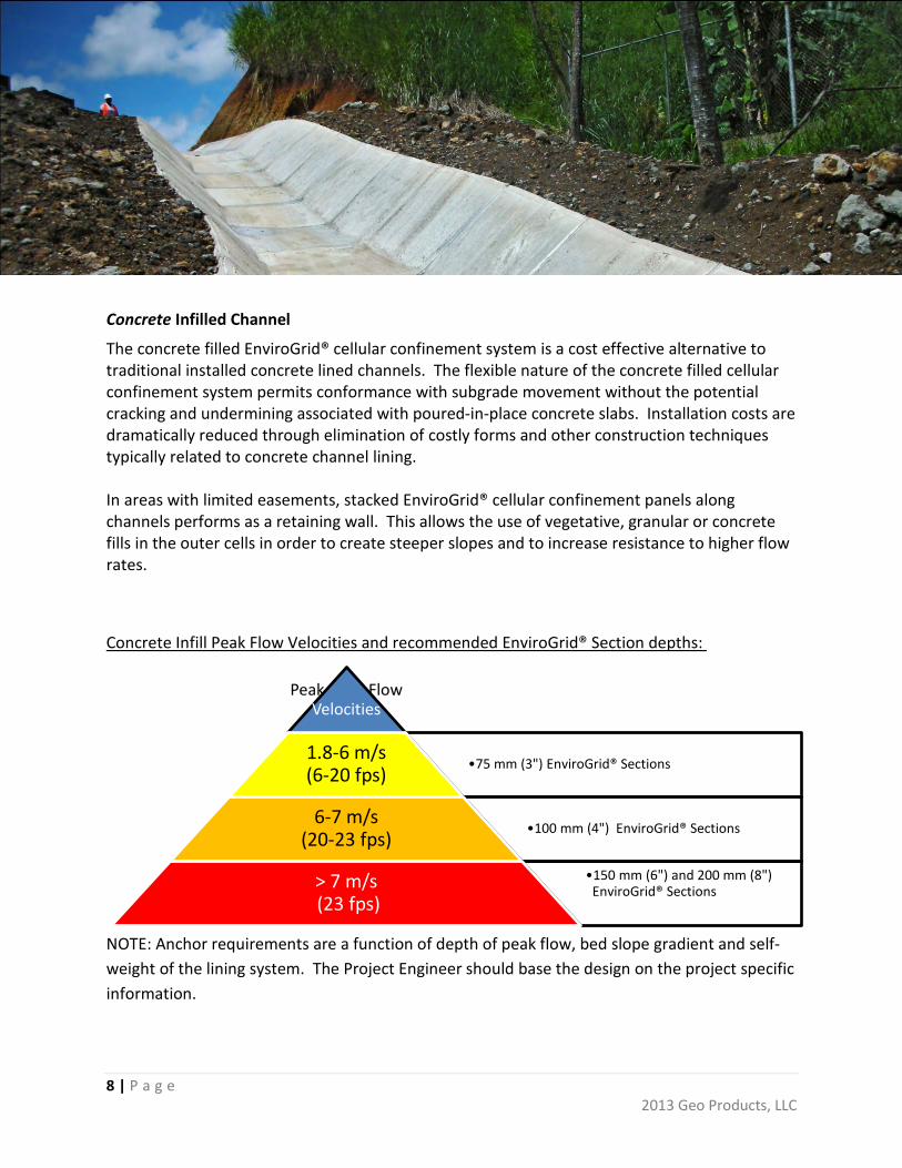
Peak Flow Velocities
•75 mm (3") EnviroGrid® Sections 1.8-6 m/s (6-20 fps)
•100 mm (4") EnviroGrid® Sections 6-7 m/s
(20-23 fps)
•150 mm (6") and 200 mm (8") EnviroGrid® Sections
> 7 m/s (23 fps)
Concrete Infilled Channel
The concrete filled EnviroGrid® cellular confinement system is a cost effective alternative to traditional installed concrete lined channels. The flexible nature of the concrete filled cellular confinement system permits conformance with subgrade movement without the potential cracking and undermining associated with poured-in-place concrete slabs. Installation costs are dramatically reduced through elimination of costly forms and other construction techniques typically related to concrete channel lining. In areas with limited easements, stacked EnviroGrid® cellular confinement panels along channels performs as a retaining wall. This allows the use of vegetative, granular or concrete fills in the outer cells in order to create steeper slopes and to increase resistance to higher flow rates. Concrete Infill Peak Flow Velocities and recommended EnviroGrid® Section depths:
NOTE: Anchor requirements are a function of depth of peak flow, bed slope gradient and self-weight of the lining system. The Project Engineer should base the design on the project specific information.
9 | P a g e 2013 Geo Products, LLC
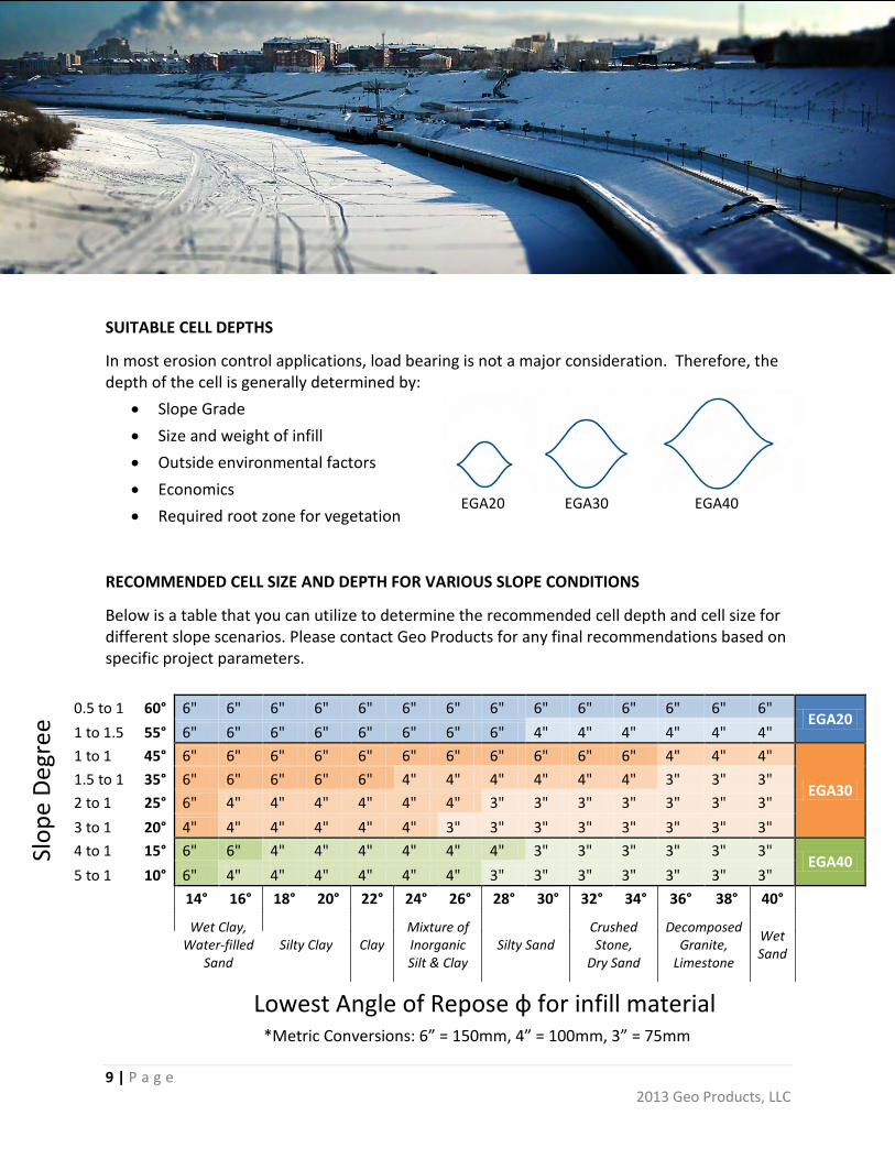
SUITABLE CELL DEPTHS
In most erosion control applications, load bearing is not a major consideration. Therefore, the depth of the cell is generally determined by:
• Slope Grade • Size and weight of infill • Outside environmental factors • Economics • Required root zone for vegetation
RECOMMENDED CELL SIZE AND DEPTH FOR VARIOUS SLOPE CONDITIONS
Below is a table that you can utilize to determine the recommended cell depth and cell size for different slope scenarios. Please contact Geo Products for any final recommendations based on specific project parameters.
Slop
e De
gree
0.5 to 1 60° 6" 6" 6" 6" 6" 6" 6" 6" 6" 6" 6" 6" 6" 6" EGA20
1 to 1.5 55° 6" 6" 6" 6" 6" 6" 6" 6" 4" 4" 4" 4" 4" 4" 1 to 1 45° 6" 6" 6" 6" 6" 6" 6" 6" 6" 6" 6" 4" 4" 4"
EGA30 1.5 to 1 35° 6" 6" 6" 6" 6" 4" 4" 4" 4" 4" 4" 3" 3" 3" 2 to 1 25° 6" 4" 4" 4" 4" 4" 4" 3" 3" 3" 3" 3" 3" 3" 3 to 1 20° 4" 4" 4" 4" 4" 4" 3" 3" 3" 3" 3" 3" 3" 3" 4 to 1 15° 6" 6" 4" 4" 4" 4" 4" 4" 3" 3" 3" 3" 3" 3"
EGA40 5 to 1 10° 6" 4" 4" 4" 4" 4" 4" 3" 3" 3" 3" 3" 3" 3"
14° 16° 18° 20° 22° 24° 26° 28° 30° 32° 34° 36° 38° 40°
Wet Clay, Water-filled
Sand Silty Clay Clay
Mixture of Inorganic Silt & Clay
Silty Sand Crushed Stone,
Dry Sand
Decomposed Granite,
Limestone
Wet Sand
Lowest Angle of Repose ф for infill material *Metric Conversions: 6” = 150mm, 4” = 100mm, 3” = 75mm
EGA20 EGA30 EGA40

10 | P a g e 2013 Geo Products, LLC
Geotextiles
Whether to use a geotextile under the EnviroGrid® is dependent on the subgrade and fill material. When the infill and subgrade are different, or if the subgrade is very soft or wet, a geotextile can provide a useful separation function by keeping the infill from migrating out from under the geocells. A geotextile is also beneficial in protecting the subgrade under the EnviroGrid® system. However, using a geotextile can reduce significantly the friction along the plane at the bottom of the EnviroGrid® system, thus increasing the net sliding force. Thus the decision whether or not to use a geotextile should be made carefully, after evaluating the benefits and costs.
11 | P a g e 2013 Geo Products, LLC
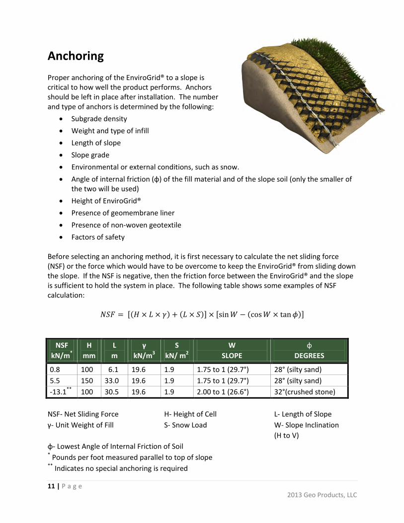
Anchoring Proper anchoring of the EnviroGrid® to a slope is critical to how well the product performs. Anchors should be left in place after installation. The number and type of anchors is determined by the following:
• Subgrade density • Weight and type of infill • Length of slope • Slope grade • Environmental or external conditions, such as snow. • Angle of internal friction (ɸ) of the fill material and of the slope soil (only the smaller of
the two will be used) • Height of EnviroGrid® • Presence of geomembrane liner • Presence of non-woven geotextile • Factors of safety
Before selecting an anchoring method, it is first necessary to calculate the net sliding force (NSF) or the force which would have to be overcome to keep the EnviroGrid® from sliding down the slope. If the NSF is negative, then the friction force between the EnviroGrid® and the slope is sufficient to hold the system in place. The following table shows some examples of NSF calculation:
𝑁𝑆𝐹 = [(𝐻 × 𝐿 × 𝛾) + (𝐿 × 𝑆)] × [sin𝑊 − (cos𝑊 × tan𝜙)]
NSF kN/m*
H mm
L m
γ kN/m3
S kN/ m2
W SLOPE
ɸ DEGREES
0.8 100 6.1 19.6 1.9 1.75 to 1 (29.7°) 28° (silty sand) 5.5 150 33.0 19.6 1.9 1.75 to 1 (29.7°) 28° (silty sand) -13.1** 100 30.5 19.6 1.9 2.00 to 1 (26.6°) 32°(crushed stone)
NSF- Net Sliding Force H- Height of Cell L- Length of Slope γ- Unit Weight of Fill S- Snow Load W- Slope Inclination
(H to V) φ- Lowest Angle of Internal Friction of Soil * Pounds per foot measured parallel to top of slope ** Indicates no special anchoring is required
12 | P a g e 2013 Geo Products, LLC
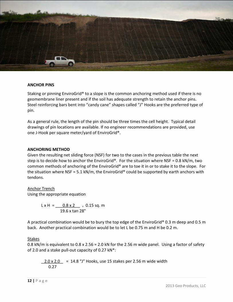
ANCHOR PINS
Staking or pinning EnviroGrid® to a slope is the common anchoring method used if there is no geomembrane liner present and if the soil has adequate strength to retain the anchor pins. Steel reinforcing bars bent into “candy cane” shapes called “J” Hooks are the preferred type of pin. As a general rule, the length of the pin should be three times the cell height. Typical detail drawings of pin locations are available. If no engineer recommendations are provided, use one J-Hook per square meter/yard of EnviroGrid®. ANCHORING METHOD Given the resulting net sliding force (NSF) for two to the cases in the previous table the next step is to decide how to anchor the EnviroGrid®. For the situation where NSF = 0.8 kN/m, two common methods of anchoring of the EnviroGrid® are to toe it in or to stake it to the slope. For the situation where NSF = 5.1 kN/m, the EnviroGrid® could be supported by earth anchors with tendons. Anchor Trench Using the appropriate equation L x H = 0.8 x 2 = 0.15 sq. m 19.6 x tan 28° A practical combination would be to bury the top edge of the EnviroGrid® 0.3 m deep and 0.5 m back. Another practical combination would be to let L be 0.75 m and H be 0.2 m. Stakes 0.8 kN/m is equivalent to 0.8 x 2.56 = 2.0 kN for the 2.56 m wide panel. Using a factor of safety of 2.0 and a stake pull-out capacity of 0.27 kN*:
2.0 x 2.0 = 14.8 “J” Hooks, use 15 stakes per 2.56 m wide width 0.27

13 | P a g e 2013 Geo Products, LLC
If the tendons are tied to earth anchors, using the same number of anchors as tendons, an additional factor safety of 1.25 to account for uncertainties in the subgrade soil:
• Stake pull-out capacity will depend upon several factors, including on-site soil conditions at their weakest, and the care with which the stakes are driven into the soil. Thus the local engineer must evaluate and make a judgment as to what value should be used.
Tendons 5.5 kN/m is equivalent to 5.5 x 2.56 = 14.1 kN for the 2.56 m wide panel. Using a factor safety of 3.0 and a tendon design strength of 13.0 kN: 14.1 x 3.0 = 3.25 tendons, use 4 tendons per 2.56 m panel width 13.0
14 | P a g e 2013 Geo Products, LLC
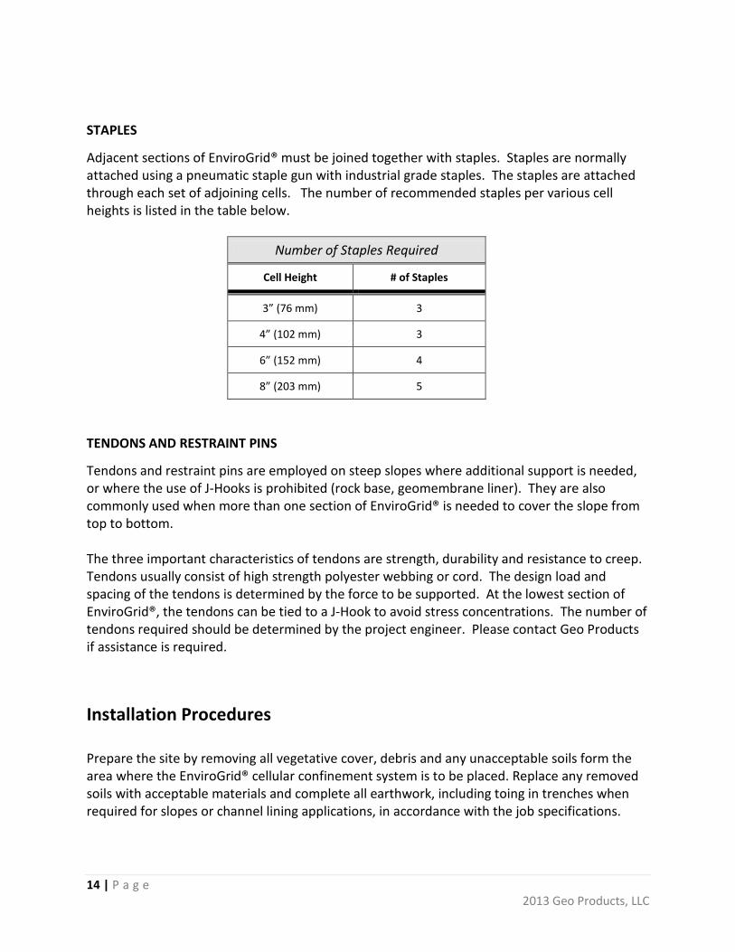
STAPLES
Adjacent sections of EnviroGrid® must be joined together with staples. Staples are normally attached using a pneumatic staple gun with industrial grade staples. The staples are attached through each set of adjoining cells. The number of recommended staples per various cell heights is listed in the table below.
Number of Staples Required
Cell Height # of Staples
3” (76 mm) 3
4” (102 mm) 3
6” (152 mm) 4
8” (203 mm) 5
TENDONS AND RESTRAINT PINS
Tendons and restraint pins are employed on steep slopes where additional support is needed, or where the use of J-Hooks is prohibited (rock base, geomembrane liner). They are also commonly used when more than one section of EnviroGrid® is needed to cover the slope from top to bottom. The three important characteristics of tendons are strength, durability and resistance to creep. Tendons usually consist of high strength polyester webbing or cord. The design load and spacing of the tendons is determined by the force to be supported. At the lowest section of EnviroGrid®, the tendons can be tied to a J-Hook to avoid stress concentrations. The number of tendons required should be determined by the project engineer. Please contact Geo Products if assistance is required. Installation Procedures Prepare the site by removing all vegetative cover, debris and any unacceptable soils form the area where the EnviroGrid® cellular confinement system is to be placed. Replace any removed soils with acceptable materials and complete all earthwork, including toing in trenches when required for slopes or channel lining applications, in accordance with the job specifications.
15 | P a g e 2013 Geo Products, LLC
If geotextile is required by the job specifications, installation should be accomplished in accordance with the manufacturer’s recommendations.
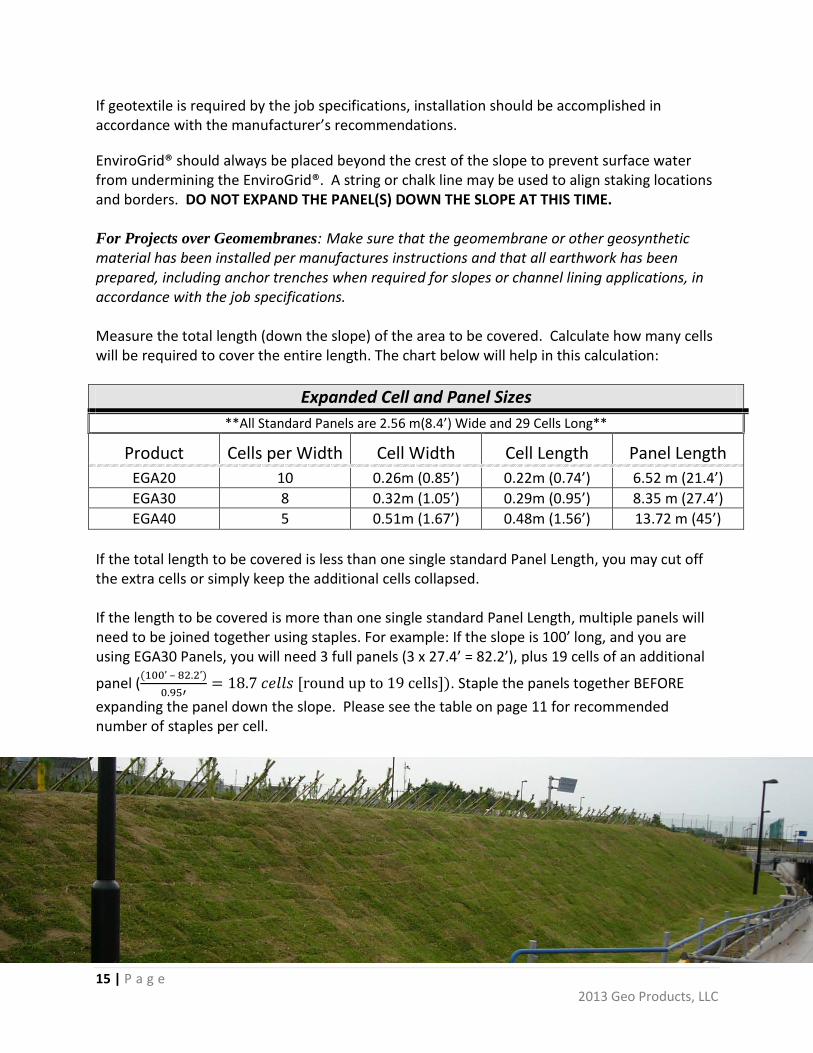
EnviroGrid® should always be placed beyond the crest of the slope to prevent surface water from undermining the EnviroGrid®. A string or chalk line may be used to align staking locations and borders. DO NOT EXPAND THE PANEL(S) DOWN THE SLOPE AT THIS TIME. For Projects over Geomembranes: Make sure that the geomembrane or other geosynthetic material has been installed per manufactures instructions and that all earthwork has been prepared, including anchor trenches when required for slopes or channel lining applications, in accordance with the job specifications. Measure the total length (down the slope) of the area to be covered. Calculate how many cells will be required to cover the entire length. The chart below will help in this calculation:
Expanded Cell and Panel Sizes **All Standard Panels are 2.56 m(8.4’) Wide and 29 Cells Long**
Product Cells per Width Cell Width Cell Length Panel Length EGA20 10 0.26m (0.85’) 0.22m (0.74’) 6.52 m (21.4’) EGA30 8 0.32m (1.05’) 0.29m (0.95’) 8.35 m (27.4’) EGA40 5 0.51m (1.67’) 0.48m (1.56’) 13.72 m (45’)
If the total length to be covered is less than one single standard Panel Length, you may cut off the extra cells or simply keep the additional cells collapsed. If the length to be covered is more than one single standard Panel Length, multiple panels will need to be joined together using staples. For example: If the slope is 100’ long, and you are using EGA30 Panels, you will need 3 full panels (3 x 27.4’ = 82.2’), plus 19 cells of an additional
panel ((100’ – 82.2’)0.95′
= 18.7 𝑐𝑒𝑙𝑙𝑠 [round up to 19 cells]). Staple the panels together BEFORE expanding the panel down the slope. Please see the table on page 11 for recommended number of staples per cell.
16 | P a g e 2013 Geo Products, LLC
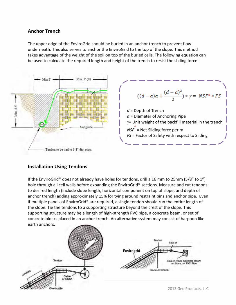
Anchor Trench The upper edge of the EnviroGrid should be buried in an anchor trench to prevent flow underneath. This also serves to anchor the EnviroGrid to the top of the slope. This method takes advantage of the weight of the soil on top of the buried cells. The following equation can be used to calculate the required length and height of the trench to resist the sliding force: Installation Using Tendons If the EnviroGrid® does not already have holes for tendons, drill a 16 mm to 25mm (5/8” to 1”) hole through all cell walls before expanding the EnviroGrid® sections. Measure and cut tendons to desired length (include slope length, horizontal component on top of slope, and depth of anchor trench) adding approximately 15% for tying around restraint pins and anchor pipe. Even if multiple panels of EnviroGrid® are required, a single tendon should run the entire length of the slope. Tie the tendons to a supporting structure beyond the crest of the slope. This supporting structure may be a length of high-strength PVC pipe, a concrete beam, or set of concrete blocks placed in an anchor trench. An alternative system may consist of harpoon like earth anchors.
d = Depth of Trench a = Diameter of Anchoring Pipe
γ= Unit weight of the backfill material in the trench
NSFa = Net Sliding force per m
FS = Factor of Safety with respect to Sliding
17 | P a g e 2013 Geo Products, LLC
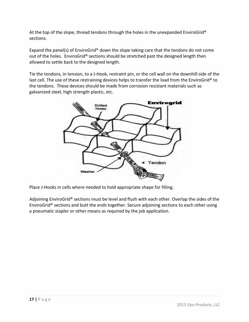
At the top of the slope, thread tendons through the holes in the unexpanded EnviroGrid® sections. Expand the panel(s) of EnviroGrid® down the slope taking care that the tendons do not come out of the holes. EnviroGrid® sections should be stretched past the designed length then allowed to settle back to the designed length. Tie the tendons, in tension, to a J-Hook, restraint pin, or the cell wall on the downhill side of the last cell. The use of these restraining devices helps to transfer the load from the EnviroGrid® to the tendons. These devices should be made from corrosion resistant materials such as galvanized steel, high strength plastic, etc. Place J-Hooks in cells where needed to hold appropriate shape for filling. Adjoining EnviroGrid® sections must be level and flush with each other. Overlap the sides of the EnviroGrid® sections and butt the ends together. Secure adjoining sections to each other using a pneumatic stapler or other means as required by the job application.

18 | P a g e 2013 Geo Products, LLC
ANCHOR PIN INSTALLATION WITH TENDONS
STEP 1: Make 2 loops in the tendon. STEP 2: Pull loop 1 partially through loop 2. STEP 3: Insert the specified J-hook anchor through loop 1 and drive J-hook into the ground until the top of hook is level with the top of the EnviroGrid® section. STEP 4: Pull both ends of tendon to close the loop and drive the J-hook until the top of it is flush with ground surface.
Install the balance of the stakes or “J” hooks. The amount of anchoring required will vary by job site conditions and many other factors. Follow the project engineer’s job specifications for location and number of anchors (J-Hooks) required. See page 13 for a guideline concerning anchors and design. The drawings below provide a recommend procedure for installing anchor pins with tendons.
When the EnviroGrid® has been properly laid in place, the system should be filled using the materials specified in the job specifications. To prevent possible damage to the system, limit the drop height of the infill to no more than 1m(40”). Infill should be delivered to the EnviroGrid® from the top of the slope or channel to the base using a front-end loader, backhoe, bucket excavator or conveyor. When using sand, granular or topsoil fills, overfill the EnviroGrid® sections by 25mm(1”) to 50 mm(2”) to allow for settling and compaction. Sand and granular fills should then be blade compacted to the top of the cells. Topsoil fills should be compacted with the loader or backhoe bucket or with a tamper plate. Concrete fills should be manually raked and machine finished.
EnviroGrid® is a registered trademark of Geo Products, LLC. Geo Products, LLC provides this information only as an accommodation to our customers. No warranty or other representation regarding the suitability of the application procedures is made due to the fact that each installation has specific requirements that may not have been considered in this generalized procedure. Geo Products, LLC makes no warranties or representations regarding the suitability of its EnviroGrid® for specific uses or applications. Our liability is limited to furnishing, without charge, a replacement for any EnviroGrid® that is proven defective under normal use and service.