Christine Perrins - Auckland Transport - Auckland Rail Development Program

erosion&sedimentcontrolGuidelines for Land Disturbing Activities in the Auckland Region
Auckland Regional Council Erosion Control: 1 1 5
Definition
The establishment and permanent stabilisation ofdisturbed areas by laying a continuous cover of grass turf.
Purpose
To provide immediate vegetative cover to stabilise soilon disturbed areas such as. For example:
o Critical erosion prone areas on the site.
o Critical areas on the site that cannot be stabilisedby conventional sowing methods.
o Runoff Diversion Channels and other areas ofconcentrated flow where velocities will not exceedthe specifications for a grass lining.
Application
Turfing is the preferred method for disturbed areas thatmust be immediately stabilised. It is particularly usefulfor:
o Watercourses and channels carrying intermittentflow.
1.6.4 Turfing
Plate 1.6.4 Turfing
o Areas around drop inlets.
o Residential or commercial lawns to allow promptuse and for aesthetic reasons.
o Steep areas.
Design
While there are no specific design criteria for Turfing,Turf reinforced with geosynthetic matting should beconsidered for areas of high erosion potential; forexample, steep slopes or concentrated overland flowpaths.
Construction Specifications
Site Preparation
Before Turfing, properly prepare the site in order toensure the successful establishment of vegetation. Thisincludes applying fertiliser as in Table 1.6 of theseGuidelines, uniformly grading the area, clearing all debris,removing stones and clods and scarifying hard packedsurfaces.

erosion&sedimentcontrolGuidelines for Land Disturbing Activities in the Auckland Region
Auckland Regional Council Erosion Control: 1 1 6
Turf Installation
During periods of high temperatures, lightly irrigate soilimmediately before laying turf.
Lay the first row of turf in a straight line with subsequentrows placed parallel to and tightly wedged against eachother. Stagger lateral joints in a brick-like pattern. Donot stretch or overlap turf and make sure all joints arebutted tight in order to prevent voids, which can causedrying of the grass roots.
On sloping areas or channels where erosion may be aproblem, lay turf downslope with the ends of the turfmaterial overlapped such that the upslope turf overlapsthe downslope turf by at least 100 mm. It may benecessary to secure the turf with pegs or staples. Ensurethe turf at the top of the slope is appropriately trenchedin to prevent runoff moving underneath it.
As Turfing is completed in one area, roll or tamp theentire area to ensure solid contact of the grass roots withthe soil surface. After rolling, immediately water the Turfuntil the underside of the new turf and soil surface belowthe turf are thoroughly wet.
Maintenance
o Water daily during the first week of laying unlessthere is adequate rainfall.
o Do not mow the area until the turf is firmly rooted.
o Apply fertiliser regularly as in Table 1.6 of theseGuidelines for ongoing successful establishment.

erosion&sedimentcontrolGuidelines for Land Disturbing Activities in the Auckland Region
Auckland Regional Council Erosion Control: 1 1 7
1.7 Geosynthetic Erosion Control Systems (GECS)
Permanent Non-Degradable GECS
These are used to extend the erosion control limits ofvegetation, soil, rock or other materials. Commonpermanent GECS are three-dimensional erosion controland revegetation mats, geocellular confinement systems,reno mattresses and gabions.
The selection of an appropriate GECS is a complexbalancing of the relative importance of the followingrequirements.
o Endurance: durability, degree of resistance todeformation over time and ultraviolet radiation andto chemicals (natural or as pollutants).
o Physical: thickness, weight, specific gravity anddegree of light penetration. Generally a thickerheavier material will provide better protection.
o Hydraulic: ability of the system to resist tractiveshear strength and protect against channel erosion,erosion of underlying soils or slope erosion fromrainfall impact.
o Mechanical: deformation and strength behaviour.Tensile strength and elongation, stiffness (how wellit will conform to the subgrade) and how well itwill resist tractive shear forces.
When a geotextile is to be used for temporary channelor spillway protection, consider combining a highstrength, low permeability cloth over a soft pliable needlepunch cloth pinned to ensure the cloth is in contact withthe entire soil surface. Trench and pin all flow entry pointssuch that the upslope geotextile edge overlaps thedownslope geotextile mat. Toe in the upslope end of thedownslope mat.
In high risk areas such as spillways and diversions, pingeotextiles down on a 0.5 o grid or in accordance withthe manufacturers’ specifications, whichever provides thegreatest number of contact points.
There is a large number of products available for allsituations and depending on the degree of protectionneeded, a product or combination of products will beavailable to suit the situation. It is vital that the productutilised is designed for the intended use and installed
Definition
The artificial protection of channels and erodible slopesutilising artificial erosion control material such asgeosynthetic matting, geotextiles or erosion matting.
Purpose
To immediately reduce the erosion potential of disturbedareas and/or to reduce or eliminate erosion on criticalsites during the period necessary to establish protectivevegetation. Some forms of artificial protection may alsohelp to establish protective vegetation.
Application
o On short steep slopes.
o On areas that have highly erodible soils.
o In situations where tensile and shear strengthcharacteristics of conventional mulches limit theireffectiveness in high runoff velocities.
o In channels (both perennial and ephemeral) wherethe design flow produces tractive shear forces greaterthan in-situ soil can withstand.
o In areas where there is not enough room to installadequate sediment controls.
o In critical erosion-prone areas such as sedimentretention pond outlet and inlet points.
o In areas that may be slow to establish an adequatepermanent vegetative cover.
o In areas where the downstream environment is ofhigh value and rapid stabilisation is needed.
Design
There are two categories of GECS; temporary degradableand permanent non-degradable.
Temporary Degradable GECS
These are used to prevent loss of seedbed and to promotevegetation establishment where vegetation alone will besufficient for site protection once established. Commontemporary GECS are erosion control blankets, openweave meshes/matting and organic erosion controlnetting (fibre mats factory-bonded to synthetic netting).

erosion&sedimentcontrolGuidelines for Land Disturbing Activities in the Auckland Region
Auckland Regional Council Erosion Control: 1 1 8
and maintained according to its specifications. Decisionanalysis techniques ranking the various GECS availableshould be used based on the following categories.
o Sediment yield (generally ranked highest)
o Stability under flow
o Vegetation enhancement
o Durability
o Cost
When installing GECS within a channel, it is importantthat the design velocity of the product is considered andagain that the product chosen is appropriate for the use.
Many products provide for the combination of arevegetation technique and an artificial erosion controlmeasure. Again, design specifications need to be closelyfollowed in all cases.
Maintenance
Inspect after every rainfall and undertake anymaintenance immediately.
Figure 1.7.1 Geotextile Laid on Slope

erosion&sedimentcontrolGuidelines for Land Disturbing Activities in the Auckland Region
Auckland Regional Council Erosion Control: 1 1 9
Figure 1.7.2 Geotextile at Culvert Outlet

erosion&sedimentcontrolGuidelines for Land Disturbing Activities in the Auckland Region
Auckland Regional Council Erosion Control: 1 2 0
Definition
A stabilised pad of aggregate on a filter cloth baselocated at any point where traffic will be entering orleaving a construction site.
Purpose
To prevent site access points from becoming sedimentsources and to help minimise dust generation anddisturbance of areas adjacent to the road frontage bygiving a defined entry/exit point.
Application
Use a Stabilised Construction Entrance at all points ofconstruction site ingress and egress with a constructionplan limiting traffic to these entrances only. They areparticularly useful on small construction sites but canbe utilised for all projects.
Design
o Clear the entrance and exit area of all vegetation,roots and other unsuitable material and properlygrade it.
o Provide drainage to carry runoff from the StabilisedConstruction Entrance to a sediment control measure.
o Place aggregate to the specifications below andsmooth it.
Table 1.8 Stabilised Construction EntranceAggregate Specifications
Aggregate Size 50 – 75 mm washed aggregate
T h i c k n e s s 150 mm minimum
L e n g t h 10 minimum
Width 4 o minimum
1.8 Stabilised Construction Entrance
Plate 1.8 Stabilised Construction Entrance

erosion&sedimentcontrolGuidelines for Land Disturbing Activities in the Auckland Region
Auckland Regional Council Erosion Control: 1 2 1
Maintenance
Maintain the Stabilised Construction Entrance in acondition to prevent sediment from leaving theconstruction site. After each rainfall inspect any structureused to trap sediment from the Stabilised ConstructionEntrance and clean out as necessary.
Figure 1.8 Stabilised Construction Entrance
When wheel washing is also required, ensure this isdone on an area stabilised with aggregate which drainsto an approved sediment retention facility.

erosion&sedimentcontrolGuidelines for Land Disturbing Activities in the Auckland Region
Auckland Regional Council Erosion Control: 1 2 2
1.9 Pipe Drop Structure/Flume
Plate 1.9 Pipe Drop Structure
Definition
A temporary pipe structure or constructed flume placedfrom the top of a slope to the bottom.
Purpose
A Pipe Drop Structure or a Flume is installed to conveysurface runoff down the face of unstabilised slopes inorder to minimise erosion on the slope face.
Application
Pipe Drop Structures or Flumes are used in conjunctionwith Runoff Diversion Channels. The Runoff DiversionChannels direct surface runoff to the Pipe Drop Structureor Flume which conveys concentrated flow down the faceof a slope. Limit the catchment area of each Pipe DropStructure or Flume to 1.0 ha. If other forms of Pipe DropStructures or Flumes are being considered, AucklandRegional Council approval of those structures will benecessary on a case by case basis.
Design
o Construct all Pipe Drop Structures or Flumes ofwatertight materials.
o Extend the Pipe Drop Structure or Flume beyondthe toe of the slope and adequately protect the outletfrom erosion using riprap over a geotextile apron.
o Use of the following Design Criteria for Pipe DropStructure, is shown in Figure 1.9.
Table 1.9 Design Criteria for Pipe DropStructure
Pipe Diameter (mm) Maximum Catchment Area (ha)
150 0 .05
3 0 0 0 . 2
4 5 0 0 . 6
5 0 0 1.0
6 0 0 1.0

erosion&sedimentcontrolGuidelines for Land Disturbing Activities in the Auckland Region
Auckland Regional Council Erosion Control: 1 2 3
o Ensure that at the Pipe Drop Structure or Flumeinlet, the height of the Runoff Diversion Channel isat least twice the pipe diameter or height of Flumeas measured from the invert.
o Install a flared entrance section of compacted earth.To prevent erosion, place impermeable geotextilefabric into the inlet extended a minimum of 1.0 oin front of and to the side of the inlet and up thesides of the flared entrance. Ensure this geotextileis keyed 150 mm into the ground along all edges.
o When the catchment area is disturbed, ensure thePipe Drop Structure or Flume discharges into aSediment Retention Pond or a stable conveyancesystem that leads to a pond. When the catchmentarea is stabilised, ensure the Pipe Drop Structure orFlume outlets onto a stabilised area at a non-erosivevelocity. The point of discharge may be protectedby rock rip rap.
o Ensure the Pipe Drop Structure or Flume has aminimum slope of 3%.
Construction Specifications for Pipe DropStructures
o A common cause of failure of Pipe Drop Structuresis water saturating the soil and seeping along thepipe where it connects to the Runoff DiversionChannel. Backfill properly around and under thepipe with stable material in order to achieve firmcontact between the pipe and the soil at all pointsto eliminate this type of failure. Pipe material usedfor the Pipe Drop Structure can consist of rigid pipematerial or flexible pipe as required. If flexible pipematerial is utilised, it is vital that the material bepinned to the slope in the required position.
o Place Pipe Drop Structures on undisturbed soil orwell-compacted fill at locations as detailed withinthe Erosion and Sediment Control Plan for the site.
o Immediately stabilise all disturbed areas followingconstruction.
o Secure the Pipe Drop Structure to the slope at leastevery 4 o. Use no less than two anchors equallyspaced along the length of the pipe.
o Ensure all pipe connections are watertight.
Construction Specifications for Flumes
o A common failure of Flumes is outflanking of theFlume entrance or scouring of the invert to the Flume.This can be prevented by waterproofing the entranceto the Flume by trenching in an appropriateimpervious geotextile or plastic liner so that all flowsare channelled directly into the flume. Alternativelya piped entrance can be installed.
o Flumes can be constructed from materials such ascorrugated steel, construction ply, sawn timber orhalved plastic piping.
o Construct the Flume to ensure there are no leaks.For wooden or plywood Flumes or Flumes whereleakage is likely, extend an impervious liner downthe full length of the Flume structure.
o For slopes greater than 30%, a Flume can beconstructed from a standard 1.2 o x 2.4 o x 22mmplywood sheet. This will be adequate for a catchmentof up to one ha. Specific design is required for largercatchments.
o Fasten the Flume to the slope using waratahs orwooden stakes placed in pairs down the slope at 1to 4 o spacings, depending on the Flume materialused. Fasten the Flume to the waratahs or stakesusing wire or steel strapping.
o Place Flumes on undisturbed soil or wellcompacted fill at locations as detailed in the site’sErosion and Sediment Control Plan.
Maintenance
o Inspect the Pipe Drop Structure/Flume periodicallyand after each rain event. Immediately carry out anymaintenance required.
o Keep the inlet open at all times.

erosion&sedimentcontrolGuidelines for Land Disturbing Activities in the Auckland Region
Auckland Regional Council Erosion Control: 1 2 4
Figure 1.9 Pipe Drop Structure

erosion&sedimentcontrolGuidelines for Land Disturbing Activities in the Auckland Region
Auckland Regional Council Erosion Control: 1 2 5
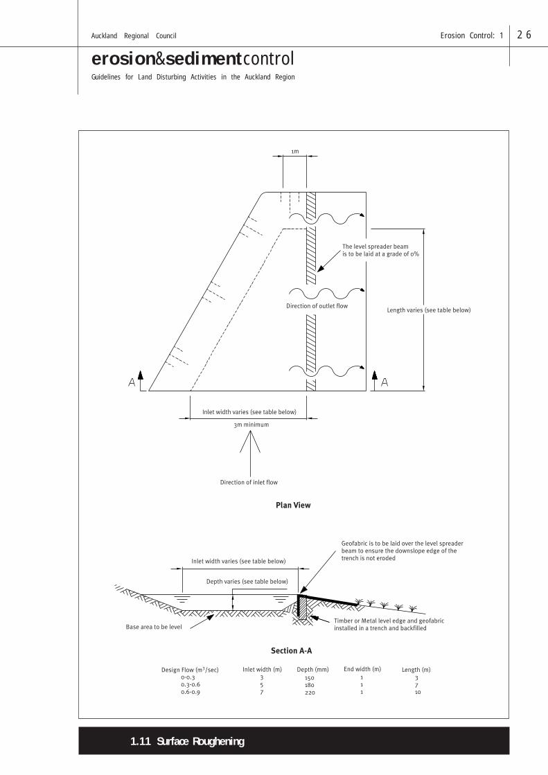
Definition
A non-erosive outlet for concentrated runoff constructedtodisperse flows uniformly across a slope.
Purpose
To convert concentrated flow to sheet flow and release ituniformly over a stabilised area to prevent erosion.
The Level Spreader provides a relatively low cost optionwhich can release concentrated flow where site conditionsare suitable. Particular care is needed to ensure the LevelSpreader outlet lip is completely level and is in stable,undisturbed soil or is well armoured. Any depressionsin the Level Spreader lip will reconcentrate flows,resulting in further erosion.
Application
o Where sediment-free storm runoff can be releasedin a sheet flow over a stabilised slope without causingerosion.
o Where sediment-laden overland flow can bereleased in sheet flow across the inlet to a SedimentRetention Pond.
o Where the area below the Level Spreader lip isuniform with the slope of 10% or less and/or isstable for the anticipated flow conditions.
o Where the runoff water will not re-concentrate afterrelease.
o Where there will be no traffic over the LevelSpreader.
Design
o Determine the capacity of the Level Spreader byestimating peak flow from the 20 year storm.
o Where possible, choose a site for the Level Spreaderthat has a natural contour that will allow for therapid spreading of flows, for example, at the end ofa knoll or ridge.
o Select the appropriate length, width and depth ofthe spreader from Table 1.10 below.
Table 1.10 Level Spreader Design Criteria
Design Flow I n l e t D e p t h End Width L e n g t h
(m3/sec) Width (o) (mm) (o) (o)
0 – 0.3 3 150 1 3
0.3 – 0.6 5 180 1 7
0.6 – 0.9 7 220 1 10
o Construct a 6 o long transition section in the RunoffDiversion Channel leading up to the Level Spreaderso the width of the Runoff Diversion Channel willsmoothly meet the width of the Level Spreader toensure uniform outflow. The Level Spreader trenchtapers down to 1 o at the end of the Level Spreader.
o Maintain a minimum inlet width of 3 o.
o Ensure that the grade of the Level Spreader is 0%.
o Construct the Level Spreader lip on undisturbedsoil, incorporating a 50 x 150 mm board (SpreaderBeam) levelled and positioned edge on as shownbelow. An alternative is to armour the Level Spreaderto a uniform height and zero grade over the lengthof the Level Spreader. Use geotextile and ensure thedisturbed area is seeded and fertilised for vegetationestablishment.
Maintenance
Inspect Level Spreaders after every rainfall untilvegetation is established and promptly undertake anynecessary repairs. Ensure vegetation is kept in a healthyand vigorous condition.
Figure 1.10 Level Spreader
1.10 Level Spreader
erosion&sedimentcontrolGuidelines for Land Disturbing Activities in the Auckland Region
Auckland Regional Council Erosion Control: 1 2 6
1.11 Surface Roughening

erosion&sedimentcontrolGuidelines for Land Disturbing Activities in the Auckland Region
Auckland Regional Council Erosion Control: 1 2 7
To aid in the establishment of vegetative cover from seed,to reduce runoff velocity, to increase infiltration, toreduce erosion and assist in sediment trapping.
Application
Apply Surface Roughening on all construction sitesrequiring slope stabilisation with vegetation, particularlyon slopes steeper than 25%.
Design
Not Applicable.
Construction Specifications
Surface Roughening is promoted by the AucklandRegional Council because it aids the establishment ofvegetation, improves infiltration and decreases runoffvelocity. Graded areas with smooth, hard surfaces maybe initially attractive but such surfaces increase thepotential for erosion. A rough, loose soil surface gives amulching effect that protects fertiliser and seed.
Various methods are available for Surface Rougheningsuch as stair step grading, discing and forming groovesby machinery tracking. Factors to be taken into accountwhen choosing a method are slope steepness, mowing/maintenance requirements and whether the slope isformed by cutting or filling.
Machinery tracking up and down the slope is therecommended method, with the cleats of the machinetracks providing a series of mini contour drains, slowingoverland flow down the slope and helping to keep thegrass seed on the slope.
Maintenance
Periodically check the slopes for rills and washes. Reseedand/or rework the area as necessary.
Purpose
DefinitionRoughening a bare earth surface with horizontal grooves
running across the slope, or tracking with construction
equipment.
Figure 1.11 Tracking
1.11 Surface Roughening

erosion&sedimentcontrolGuidelines for Land Disturbing Activities in the Auckland Region
Auckland Regional Council Erosion Control: 1 2 8
Dozer cleats create grovesperpendicular to the slope
Slope