
Design and Implementation of the - amslaurea.unibo.it · Corso di Laurea Triennale in Informatica...
93
Alma Mater Studiorum · Università di Bologna FACOLTÀ DI SCIENZE MATEMATICHE, FISICHE E NATURALI Corso di Laurea Triennale in Informatica Design and Implementation of the μMPS2 Educational Emulator Tesi di Laurea in Progetto di Sistemi Virtuali Relatore: Prof. Renzo Davoli Presentata da: Tomislav Jonjic Sessione II Anno Accademico 2011-2012
Transcript of Design and Implementation of the - amslaurea.unibo.it · Corso di Laurea Triennale in Informatica...

Alma Mater Studiorum · Università di Bologna
FACOLTÀ DI SCIENZE MATEMATICHE, FISICHE E NATURALICorso di Laurea Triennale in Informatica
Design and Implementation of theµMPS2 Educational Emulator
Tesi di Laurea in Progetto di Sistemi Virtuali
Relatore:Prof. Renzo Davoli
Presentata da:Tomislav Jonjic
Sessione IIAnno Accademico 2011-2012


Design and Implementation of theµMPS2 Educational Emulator
Tomislav Jonjic
Abstract
An arguably critical part of any computer science curriculum consists of experi-ence in designing non-trivial software systems. A first course in operating systemsprovides adequate ground for this endeavor, as any reasonably featured operatingsystem is an intrinsically complex program. An operating system builds layers of ab-straction upon the bare machine interface; understanding—or better yet devising—such a system encourages one to acquire a solid command of software engineeringprinciples and heuristics. Modern machine architectures, it is argued in this the-sis, are prohibitively complex and thus unsuitable as foundations for educational orexperimental proof-of-concept operating systems. A preferable alternative, then, isprovided by emulators of reasonably realistic but at the same time pedagogicallysound hardware platforms. This thesis builds upon one such system, namely µMPS[1]—a tool primarily devised as an aid in operating systems and beginner-level com-puter architecture university courses. µMPS features an accessible architecture, cen-tered around a MIPS R3000 processor, that includes a rich set of easily programmabledevices.
The first major revision of µMPS is the result of the present thesis. Amongthe prominent features of this new version, dubbed µMPS2 [2], are multiprocessorsupport and a more sophisticated and easier to use user interface. The primary goalof the architecture revision was to make the system reflect reasonably well moderncommodity hardware platforms, for which the clear trend over the past several yearshas been a shift towards multi-core designs.
After an overview of the machine architecture and the emulator environment,a relatively thorough exposition of the emulator internals is given. Considerablecare was taken to ensure that the code base is accessible enough to foster furtherexperimentation, for which possible directions are given in the last chapter.


Progettazione e implementazionedell’emulatore didattico µMPS2
Tomislav Jonjic
Sommario
Una componente importante di qualsiasi curriculum universitario di informatica èindubbiamente l’esperienza nella progettazione di sistemi software di non banalecompletessità. Un corso introduttivo di sistemi operativi rappresenta un contestoopportuno per questo scopo, visto che un sistema operativo è in generale un pro-gramma intrinsecamente complesso. Un sistema operativo va visto come una se-rie di livelli di astrazione, a partire da quello basato sull’interfaccia esposta dallamacchina stessa. La comprensione, ed a maggior ragione la progettazione, di un talesistema non può prescindere da un’adeguata acquisizione di conoscenze dall’ambitodell’ingengeria del software. Le piattaforme hardware moderne, si sostiene in questatesi, sono eccessivamente complesse, e di conseguenza non adatte come basi per sis-temi operativi didattici oppure quelli altamente sperimentali. Un’alternativa miglioreconsiste nell’impiego di emulatori di piattaforme hardware ragionevolmente realis-tiche ma allo stesso tempo di concezione espressamente didattica. Questa tesi èbasata su un tale sistema, chiamato µMPS [1]—uno strumento ideato principalmenteper l’impiego sia nei corsi universitari di sistemi operativi che quelli introduttivi diarchitettura degli elaboratori. µMPS vanta di un’archiettura pedagogicamente acces-sibile, in base alla quale si trova un processore MIPS R3000 e che include un’ampiaserie di dispositivi facilmente programmabili.
Il primo considerevole aggiornamento di µMPS è il risultato della presente tesi.Tra le caratteristiche notevoli della nuova versione, denominata µMPS2 [2], trovi-amo il supporto multiprocessore e un’interfaccia utente più usabile e sofisticata dellaprecedente. L’obbiettivo principale della revisione dell’architettura è stato quello dirispecchiare meglio con µMPS2 le comuni piattaforme hardware moderne, per lequali si è vista una chiara e crescente tendenza verso le architetture multi-core.
Dopo una panoramica dell’architettura di µMPS2 e dell’interfaccia utente, segueun’esposizione relativamente approfondita dell’implementazione dell’emulatore. Du-rante lo sviluppo di questo si è posta particolare attenzione alla mantenibilità e sem-plicità del codice, con lo scopo di incoraggiare futuri sviluppi; alcune direzioni pos-sibili per questi sono date nell’ultimo capitolo.


Contents
1 Introduction 11.1 Background . . . . . . . . . . . . . . . . . . . . . . . . . . . . . . . . . . 11.2 The µMPS Project . . . . . . . . . . . . . . . . . . . . . . . . . . . . . . . 21.3 Applications of µMPS . . . . . . . . . . . . . . . . . . . . . . . . . . . . 31.4 Contributions of This Work . . . . . . . . . . . . . . . . . . . . . . . . . 41.5 Organization of this Document . . . . . . . . . . . . . . . . . . . . . . . 4
2 An Overview of the µMPS2 Architecture 72.1 Introduction . . . . . . . . . . . . . . . . . . . . . . . . . . . . . . . . . . 72.2 Overall System Structure . . . . . . . . . . . . . . . . . . . . . . . . . . . 72.3 Processor Architecture . . . . . . . . . . . . . . . . . . . . . . . . . . . . 8
2.3.1 µMPS2-Specific ISA Features . . . . . . . . . . . . . . . . . . . . 82.4 Devices and Interrupt Management . . . . . . . . . . . . . . . . . . . . 10
2.4.1 Interrupts in µMPS2 . . . . . . . . . . . . . . . . . . . . . . . . . 102.4.2 Interrupt Line Assignment and Source Resolution . . . . . . . . 112.4.3 Interrupt Management in Multiprocessor Systems . . . . . . . . 11
2.5 Higher Level Abstractions Through Firmware . . . . . . . . . . . . . . 112.5.1 Higher-Level Exception-Handling Interface . . . . . . . . . . . 122.5.2 Higher-Level Virtual Memory Interface . . . . . . . . . . . . . . 12
2.6 Further References . . . . . . . . . . . . . . . . . . . . . . . . . . . . . . 13
3 The µMPS2 Emulator: A User’s View 153.1 Introduction . . . . . . . . . . . . . . . . . . . . . . . . . . . . . . . . . . 153.2 User Interface Organization . . . . . . . . . . . . . . . . . . . . . . . . . 153.3 Machine Configurations . . . . . . . . . . . . . . . . . . . . . . . . . . . 16
3.3.1 Installed Devices and Device Files . . . . . . . . . . . . . . . . . 183.3.2 Byte Order in µMPS . . . . . . . . . . . . . . . . . . . . . . . . . 18
3.4 Machine Control and Monitoring . . . . . . . . . . . . . . . . . . . . . . 193.4.1 Startup and Shutdown . . . . . . . . . . . . . . . . . . . . . . . . 193.4.2 Execution Control . . . . . . . . . . . . . . . . . . . . . . . . . . 193.4.3 Breakpoints and Suspects . . . . . . . . . . . . . . . . . . . . . . 213.4.4 Examining Processor State . . . . . . . . . . . . . . . . . . . . . 223.4.5 Memory View . . . . . . . . . . . . . . . . . . . . . . . . . . . . . 233.4.6 Device Monitoring . . . . . . . . . . . . . . . . . . . . . . . . . . 24
i

ii Contents
3.4.7 Terminals . . . . . . . . . . . . . . . . . . . . . . . . . . . . . . . 243.5 Programming for µMPS2 . . . . . . . . . . . . . . . . . . . . . . . . . . 25
3.5.1 ROM Images . . . . . . . . . . . . . . . . . . . . . . . . . . . . . 253.5.2 The Toolchain . . . . . . . . . . . . . . . . . . . . . . . . . . . . . 263.5.3 Object File Formats . . . . . . . . . . . . . . . . . . . . . . . . . . 273.5.4 Operating System Bootstrap . . . . . . . . . . . . . . . . . . . . 27
3.6 Further References . . . . . . . . . . . . . . . . . . . . . . . . . . . . . . 27
4 µMPS2 Emulator Internals 294.1 Design Principles and Overall Structure . . . . . . . . . . . . . . . . . . 29
4.1.1 Signals, Slots, and the Observer Pattern . . . . . . . . . . . . . . 304.1.2 Portability and the Choice of Implementation Language . . . . 304.1.3 Source Tree Structure . . . . . . . . . . . . . . . . . . . . . . . . 31
4.2 The Emulation Core . . . . . . . . . . . . . . . . . . . . . . . . . . . . . 324.2.1 Machine Configurations and Machine Instances . . . . . . . . . 334.2.2 Processor Emulation . . . . . . . . . . . . . . . . . . . . . . . . . 344.2.3 Device Emulation . . . . . . . . . . . . . . . . . . . . . . . . . . . 374.2.4 Virtual Time, Machine Cycles, and Event Management . . . . . 384.2.5 Debugging Support . . . . . . . . . . . . . . . . . . . . . . . . . 394.2.6 High-Level View of the Emulation API . . . . . . . . . . . . . . 39
4.3 The User Interface Implementation . . . . . . . . . . . . . . . . . . . . . 404.3.1 The Qt Framework . . . . . . . . . . . . . . . . . . . . . . . . . . 404.3.2 Models and Views . . . . . . . . . . . . . . . . . . . . . . . . . . 404.3.3 Machine Execution . . . . . . . . . . . . . . . . . . . . . . . . . . 414.3.4 Class and Module Overview . . . . . . . . . . . . . . . . . . . . 44
4.4 µMPS2 Object File Support Tools . . . . . . . . . . . . . . . . . . . . . . 464.4.1 ELF to .aout Conversion . . . . . . . . . . . . . . . . . . . . . . . 46
5 Conclusions 515.1 Suggestions for Further Experiments . . . . . . . . . . . . . . . . . . . . 51
5.1.1 Detailed Simulation . . . . . . . . . . . . . . . . . . . . . . . . . 515.1.2 Emulator Scalability . . . . . . . . . . . . . . . . . . . . . . . . . 525.1.3 An Operating System for µMPS2 . . . . . . . . . . . . . . . . . . 53
A µMPS2 Architecture Revision 55A.1 Machine Control Registers . . . . . . . . . . . . . . . . . . . . . . . . . . 55
A.1.1 Processor Power States . . . . . . . . . . . . . . . . . . . . . . . . 56A.1.2 Processor Initialization . . . . . . . . . . . . . . . . . . . . . . . . 56A.1.3 Powering Off the Machine . . . . . . . . . . . . . . . . . . . . . . 57
A.2 New and Revised CP0 Registers . . . . . . . . . . . . . . . . . . . . . . 57A.2.1 PRID Register . . . . . . . . . . . . . . . . . . . . . . . . . . . . . 57A.2.2 The On-CPU Interval Timer . . . . . . . . . . . . . . . . . . . . . 58A.2.3 Status Register . . . . . . . . . . . . . . . . . . . . . . . . . . . . 59A.2.4 Backward Compatibility Notes . . . . . . . . . . . . . . . . . . . 59

Contents iii
A.3 Multiprocessor Interrupt Control . . . . . . . . . . . . . . . . . . . . . . 59A.3.1 Interrupt Distribution . . . . . . . . . . . . . . . . . . . . . . . . 59A.3.2 CPU Interface Registers . . . . . . . . . . . . . . . . . . . . . . . 60A.3.3 Inter-processor Interrupts (IPIs) . . . . . . . . . . . . . . . . . . 61
A.4 New Instructions . . . . . . . . . . . . . . . . . . . . . . . . . . . . . . . 63A.4.1 Compare and Swap (CAS) . . . . . . . . . . . . . . . . . . . . . 63A.4.2 Wait for Event (WAIT) . . . . . . . . . . . . . . . . . . . . . . . . 64
A.5 BIOS Services . . . . . . . . . . . . . . . . . . . . . . . . . . . . . . . . . 64A.6 Device Register Memory Map . . . . . . . . . . . . . . . . . . . . . . . . 65
B Machine Configuration Format 67


List of Figures
3.1 The main window . . . . . . . . . . . . . . . . . . . . . . . . . . . . . . . 163.2 General machine configuration parameters . . . . . . . . . . . . . . . . 173.3 Device settings . . . . . . . . . . . . . . . . . . . . . . . . . . . . . . . . 183.4 The main window’s processor tab pane . . . . . . . . . . . . . . . . . . 213.5 The breakpoint insertion dialog . . . . . . . . . . . . . . . . . . . . . . . 223.6 The processor window . . . . . . . . . . . . . . . . . . . . . . . . . . . . 233.7 The main window’s memory tab . . . . . . . . . . . . . . . . . . . . . . 243.8 Device status view . . . . . . . . . . . . . . . . . . . . . . . . . . . . . . 253.9 The terminal window . . . . . . . . . . . . . . . . . . . . . . . . . . . . . 26
4.1 The MIPS five-stage pipeline and delayed branches . . . . . . . . . . . 364.2 The model-view architecture of the µMPS2 emulator . . . . . . . . . . 42
A.1 Processor power states . . . . . . . . . . . . . . . . . . . . . . . . . . . . 56A.2 The Status CP0 register . . . . . . . . . . . . . . . . . . . . . . . . . . 59A.3 IRT entry format . . . . . . . . . . . . . . . . . . . . . . . . . . . . . . . 60A.4 IRT register address map . . . . . . . . . . . . . . . . . . . . . . . . . . 61A.5 The TPR register . . . . . . . . . . . . . . . . . . . . . . . . . . . . . . . . 61A.6 The Outbox register . . . . . . . . . . . . . . . . . . . . . . . . . . . . . 62A.7 The Inbox register . . . . . . . . . . . . . . . . . . . . . . . . . . . . . . 62A.8 Device register memory map . . . . . . . . . . . . . . . . . . . . . . . . 65
v


List of Tables
A.1 Machine control registers address map . . . . . . . . . . . . . . . . . . 55A.2 CP0 registers . . . . . . . . . . . . . . . . . . . . . . . . . . . . . . . . . . 57A.3 Interrupt line assignment in µMPS2 . . . . . . . . . . . . . . . . . . . . 58A.4 Interrupt controller processor interface register map . . . . . . . . . . . 61
vii


Listings
4.1 A sample machine configuration. . . . . . . . . . . . . . . . . . . . . . . 334.2 A linker script for .aout executables. . . . . . . . . . . . . . . . . . . . . 48B.1 A JSON Schema for the µMPS2 machine configuration format. . . . . 67
ix


Notational Conventions
Several notational and typographical conventions are employed throughout the text:
• A bold typewriter-like typeface is used for machine registers (including pro-cessor registers and device registers) and register fields, as in Status;
• R.F denotes the field F of register R;
• Processor exception mnemonics are typeset in italic, as in AdES;
• A typewriter-like typeface is used for instructions, file names, identifiers, andcode fragments, as in jalr.
xi


Chapter 1
Introduction
1.1 Background
We begin this exposition with a brief account of the motivations behind the originalwork we build upon in this thesis. Rather than for its own interest or value, wechoose to do so mainly because it will help elucidate many design choices describedlater on in this document.
Most computer science curricula have for a long time included a course in op-erating systems [3, 4]. This is rather fortunate, since many other areas of computerscience find application in operating systems and, conversely, many notions stud-ied within operating systems research are likely to be useful in other subfields ofcomputer science. Operating system kernels of even moderate sophistication willundoubtedly make use of a variety of well known algorithms and data structures.An undergraduate course in operating systems also represents a very natural settingfor a first introduction to concurrency. Finally, the course offers an outstanding op-portunity for the student to review the engineering aspects of computer science. Anoperating system is an inherently complex computer program, whose design and im-plementation ultimately depends on the student’s ability to apply sound techniquesof abstraction to manage an otherwise overwhelming complexity. By participatingin the design and implementation process, the student can acquire experience instructuring large software systems in general.
For reasons we have outlined above, a course in operating systems should, ratherthan adopting a purely descriptive approach, ideally include in its program the studyand possibly an implementation of a complete operating system. Such an approachto teaching operating systems is by no means new, as evidenced by several influentialtextbooks devised, at least in part, to support it. As notable examples, we mentionLions’ book on the 6th edition UNIX system [5], Bach’s book on the internals ofUNIX System V Release 2 [6], and Tanenbaum’s book on MINIX [7]. Beside havinghad considerable influence on future operating systems course curriculums, it is notunreasonable to argue that the aforementioned works had an impact on the industryas well. All of the mentioned books describe existing, complete, operating systems.At the other extreme, the instructor may choose to assign the task of designing and
1

2 Chapter 1. Introduction
implementing the operating system to students (with proper guidance, of course).While both approaches unquestionably have their own merits, the latter arguablyresults in educationally more rewarding experiences [8, 9].
An instructor that chooses to assign the task of developing an operating system tostudents is unavoidably posed with a problem: which machine architecture shouldthe course target? One obvious answer would be to simply use any variant of mod-ern architectures currently in use—after all, shouldn’t one focus on technologies thatare relevant today and thus likely to remain so for the foreseeable future? Unfor-tunately, modern hardware is overwhelmingly complex—coming to terms with thequirks and complexities of today’s hardware would simply take a disproportionateamount of time for a typical one-semester course. µMPS is an educational computersystem architecture and emulator that was designed specifically to be pedagogicallysound: it provides a streamlined version of most features typically found on mod-ern computer systems. We argue in this thesis that µMPS is an ideal fit for theabove-mentioned use case.
1.2 The µMPS Project
The goal of the µMPS project, as was already noted, has been to develop a computersystem architecture and supporting software— that is, the “courseware”, of whichthe machine emulator constitutes the most important part—especially tailored tocomputer science education. This reflects in two often contrasting requirements: onone hand, the architecture should be representative of real ones (that is, reasonablyrealistic), and on the other hand it should be considerably simpler than those.
The original version of the architecture and accompanying courseware, calledMPS [10], were authored at the University of Bologna by Mauro Morsiani, underthe supervision of Renzo Davoli. The system was centered around a single MIPSR3000 processor, a member of the MIPS architecture line, which was at the time al-ready becoming well established in computer science education as a prime exampleof an elegant, clean, instruction set architecture. The system specification also de-tailed a rich set of peripheral devices and a system bus along with their supportingcontrollers. Later revisions of the architecture and courseware, including the latestµMPS2, remained identical in spirit to the original version. (We present a brief intro-duction to the architecture in Chapter 2; for a detailed and authoritative descriptionwe refer the reader to [11].)
µMPS [1] was a slight evolution of MPS, motivated by the experience and feed-back from using MPS in undergraduate operating systems courses taught by RenzoDavoli at the University of Bologna and Michael Goldweber at Xavier University. Ona hardware level, this version introduced a streamlined and more orthodox virtualmemory subsystem. Interestingly, the new virtual memory subsystem was imple-mented almost entirely using ROM level abstractions and required only minor mod-ifications to the processor architecture. On the emulator level, µMPS featured a morenovice-friendly graphical user interface.

1.3. Applications of µMPS 3
The µMPS architecture is, as of writing, in its second major revision, labeledµMPS2, and implemented by the 2.x series of the emulator. Multiprocessor supportis the single most important feature of µMPS2. With this addition, µMPS remainscomparable in feature with the current generation of consumer-class computer sys-tems.
1.3 Applications of µMPS
The original inspiration for the µMPS project, and perhaps still the driving motiva-tion and most important use case, is the one we have already given above: to providea didactically sound hardware platform for use by educational—whether academicor hobby—operating system projects. We see µMPS as ideally suited for this use casebecause it represents an acceptable compromise between realism and simplicity. In-deed, the current revision of the architecture does not deviate appreciably from thatof a contemporary workstation or small server class system. At the same time, thevarious hardware subsystems in µMPS exclude the gratuitous complexity presentin virtually all real-world hardware that would unnecessarily hinder the learningprocess.
µMPS can also be a valuable aid in a first introduction to MIPS assembly lan-guage programming. This topic is often selected as a small but important part ofan introductory course in computer architecture, since it can help explicate manyaspects of the hardware/software interface. An assembly level MIPS simulator suchas SPIM [12] or MARS [13] is typically used to execute programs written in MIPSassembly. Unlike µMPS or other emulators, these programs do not interpret actualmachine code; instead, they interpret MIPS assembly language programs directly.Consequently, using µMPS requires slightly more effort compared to an assemblysimulator, since a development toolchain (an assembler and linker at minimum) isneeded to prepare programs for the machine. The features provided by µMPS, suchas its support for many peripheral devices or the emulator’s debugging features maywell be worth the additional effort.
Finally, we believe that µMPS provides a good basis for experimentation in com-puter system emulation, especially in the area of educational applications. The pri-mary reason for this is the relative simplicity of the µMPS system and emulator,compared to prominent full system emulators, such as QEMU [14]. Since these em-ulators are expected to efficiently execute real-world operating systems and realisticworkloads, they put first and foremost an emphasis on performance, at the cost ofcode complexity. As such, these highly optimized systems are inevitably both lesssuited for experimentation and less amenable to extensions. We give some possibledirections for future extensions in Chapter 5.

4 Chapter 1. Introduction
1.4 Contributions of This Work
Only several years ago, consumer desktop systems were virtually without exceptionuniprocessor systems. Multiprocessor architectures were economically viable onlyfor server systems and, to a lesser extent, specialized high-performance worksta-tions. In the meantime, however, the industry has has shifted focus to multiproces-sor designs for high-end and commodity systems alike. This was primarily a resultof ever more diminishing returns from instruction-level parallelism and of power is-sues. Multi-core machines are now ubiquitous on desktop or even mobile hardwareand this trend is most certainly going to continue. As a result, general purpose op-erating systems designs—whether educational or not—that target only uniprocessorsystems are at the very least considered obsolete. The single processor design ofµMPS was in this regard a serious limitation.
This thesis resulted from the attempt to bring µMPS to the era of thread-level par-allelism. µMPS2 includes relatively sophisticated multiprocessor support, modeledafter existing hardware but appreciably streamlined in comparison.
Extending the µMPS emulator to support the µMPS2 architecture created an op-portunity to reconsider various design choices behind the emulator. An importantaspect—certainly the most visible to end users—in which the µMPS2 emulator dif-fers from its predecessors is the user interface, which has been redesigned to betterfit modern user interface standards and the expectations of today’s users.
1.5 Organization of this Document
This chapter introduced µMPS, its scope, and its use. In the remainder of this work,we present an overview of the µMPS2 architecture and emulator (referring the readerto the official documentation for full details) as well as information on the emulatorinternals.
Chapter 2 outlines the µMPS2 architecture. Although finer details of the archi-tecture are not given (such as device controller programming information or detailson machine registers), it contains enough background material to allow the readerunfamiliar with the architecture to follow later chapters. In addition, Appendix Adescribes in detail the changes in the µMPS2 revision of the architecture.
Chapter 3 gives a user’s perspective of the µMPS2 emulator. It describes the mostimportant parts of the user interface and the means by which emulated machines canbe created and executed.
Chapter 4 dwells on the internals of the µMPS2 emulator. The material willespecially be of interest to the reader who is required to understand the emulatorcode (that is, the prospective maintainer or contributor). Both the emulation back-end and the front-end (user interface) components are described in fair detail.
Finally, in Chapter 5 we attempt to give an objective view on the overall successof the µMPS project thus far. We also list possible directions for future work. Inparticular, an ongoing experimental project is described that aims to mitigate the

1.5. Organization of this Document 5
multiplicative slowdown due to emulation of multiprocessor machines, by exploitingthread-level parallelism at the host level (at the expense of deterministic execution).


Chapter 2
An Overview of the µMPS2Architecture
2.1 Introduction
The µMPS hardware platform is, by design, considerably easier to program thanones typically found in actual computer systems today. This design goal is reflectedboth in the choice of the base instruction set architecture and (especially) the devicecontroller interfaces that comprise the system. In this chapter, we briefly describethese design choices and give a short overview of the µMPS2 architecture, withthe intent to present just enough details to allow one to comfortably follow theremainder of this work.
2.2 Overall System Structure
µMPS2 includes features commonly found in a modern server or workstation classmultiprocessor machine, albeit in simplified form. In a nutshell, the µMPS2 com-puter system is composed of:
• Up to sixteen MIPS R3000-style processors (µMPS2-specific parts of the instruc-tion set architecture are described in Section 2.3).
• Device controllers for five device types (terminals, disks, tape readers, printers,and network adapters).
• Various support hardware, including a programmable multiprocessor interruptcontroller.
• A system bus connecting the above units. The bus controller integrates a sys-tem clock and an interval timer. These devices are interfaced through a mem-ory mapped register interface, which also includes registers that provide criti-cal system information.
7

8 Chapter 2. An Overview of the µMPS2 Architecture
2.3 Processor Architecture
The µMPS2 processor architecture is based on the one implemented by MIPS Com-puter System’s R2000 and R3000 models, the earliest members of the MIPS line ofprocessors. This architecture, labeled MIPS-I, grew out of the research project of thesame name at Stanford University, led by John L. Hennessy [15]. The key insight be-hind the project was that an instruction set composed of relatively simple operationswas amenable to an efficient implementation using the technique of pipelining, thefirst of many micro-architectural techniques that were used by subsequent designsto exploit instruction level parallelism. The MIPS design was commercialized in 1986by MIPS Computer Systems Inc., in the form of the R2000 processor.
The choice of instruction set architecture (ISA) was motivated by the MIPS archi-tecture’s virtue of being both didactically sound and well supported by existing com-pilers and tools. The MIPS-I instruction set is arguably the most elegant 32-bit ISAamong those server and workstation-class architectures that have seen widespreadadoption in the industry. The best evidence of this is its use in computer scienceeducation; as just one concrete example, we mention Hennessy and Patterson’s in-fluential introductory textbook on computer architecture [12].
2.3.1 µMPS2-Specific ISA Features
The instruction set implemented by the µMPS2 CPU is, from a user-level program-ming perspective, a strict superset1 of the MIPS-I ISA, as implemented by the R2000and R3000 processors. This is of fundamental importance for the µMPS project,since this level of (backward) compatibility means that µMPS can be automaticallysupported by existing MIPS compilers.
It is in the system control coprocessor (known as CP0 across MIPS architecturerevisions) inteface—relevant from a system programming perspective—that µMPS2slightly departs from the R3000 processor. Such incompatibilities are irrelevantfor compiled code and most (if not all) higher-level software in general, since theCPU control interfaces are never targeted by compiled code. Indeed, prior to theMIPS32/64 revision of the MIPS architecture, the system control coprocessor’s in-terface was implementation dependent; in this sense, the µMPS2 CPU is a strictlyconforming implementation of the MIPS-I ISA.
Memory Management Support
Like the R3000 family of processors, the µMPS2 processor integrates support fora paged memory management scheme; the key hardware unit behind this sup-port is the on-chip translation lookaside buffer (TLB), which in µMPS2 is of user-configurable size. On all MIPS architectures, the TLB is entirely software-managed;
1µMPS2 does not include floating-point support, an optional part of the MIPS-I ISA defined in thecoprocessor 1 encoding space.

2.3. Processor Architecture 9
the notion of page table in particular is not defined by the hardware architecture atall.
Program (or “virtual”) addresses in the R3000 and any later MIPS CPU are alwayssubject to a form of translation—a program address is never equal to the effectivephysical address output by the CPU. µMPS2 introduces two modes of operation forthe processor’s memory management subsystem:
• a physical memory mode for which address translation via the TLB is not em-ployed and program addresses correspond to physical ones in a straightfor-ward manner;
• a virtual memory mode, in which address translation is used for all addressesapart from those in the range reserved for memory mapped I/O and ROMcode.
As described in Section 2.5.2, the standard firmware supplied with µMPS2, build-ing on the low-level virtual memory support, introduces a hybrid segmented-pagedscheme which is for most purposes more convenient from an operating system’sprogrammer perspective.
Cache Control
Most architectural components of the R3000 used specifically for cache managementare not included in µMPS2. This is for instance the case with all the fields in theR3000 CP0 Status registers that are used for cache control and diagnostics. Froma practical point of view, each µMPS2 processor can be thought of as fully cache-coherent.
Integrated Interval Timer
Like recent MIPS processors, each µMPS2 processor includes an on-processor pro-grammable interval timer. Readers familiar with the MIPS32/64 architecture revi-sions should be wary that, while the timer performs the same function as the oneprovided by the MIPS32/64 Count and Compare registers, it exposes a differentprogramming interface.
Instruction Set Extensions
In addition to features added via the implementation-specific CP0 registers, µMPS2augments the core MIPS-I instruction set with some new instructions:
• The wait instruction, borrowed from newer MIPS ISA revisions, is used topause the CPU until an external event occurs. This instruction is analogous tothe HLT instruction in the x86 architecture, for example.

10 Chapter 2. An Overview of the µMPS2 Architecture
• The cas instruction is a version of the well known compare-and-set (or compare-and-swap) atomic instruction, adopted by several contemporary architectures,among which are SPARC v9 and x86-64.2
2.4 Devices and Interrupt Management
µMPS2 supports device controllers for five different types of peripheral devices:
• Disk devicesµMPS2 disk devices are classic DMA-capable hard disk drives of configurablegeometry.
• Tape devicesTape drives in µMPS2 are read-only devices. Like disks, tape devices supportDMA.
• Network devicesµMPS2 supports DMA-capable Ethernet adapters.
• Printer devicesPrinters in µMPS2 are text-only output peripherals, attached on a 8-bit parallelinterface.
• Terminal devicesThese devices, used for text input and display, are a simplified version of theclassic serial text terminal. Terminal devices are physically divided into twodevices: a transmitter and a receiver.
Up to eight instances of each device type can be included in any µMPS2 machine,each one supported by the corresponding device controller. Device controllers areprogrammed via memory mapped hardware registers. The register-level interface isto a large extent uniform across device types.
2.4.1 Interrupts in µMPS2
All device controllers in µMPS2 support an interrupt-driven programming model: adevice operation is requested by setting appropriate hardware registers; upon com-pletion, an interrupt is generated and device registers are updated accordingly; the
2MIPS architectures levels starting from MIPS-II include a pair of instructions called load-linked andstore-conditional (LL/SC) instead of CAS for the purpose of building synchronization primitives. Em-ulating LL/SC efficiently proves to be considerably more difficult, however. Since compatibility withMIPS-II and later instruction sets was not a requirement for µMPS2, this was an important consid-eration in the selection of an atomic read-modify-write primitive for µMPS2. As shown in [16], theexpressive power of compare-and-set matches that of LL/SC. Furthermore, CAS and LL/SC are uni-versal primitives, which means, in simple terms, that they can be used to implement a non-blockingimplementation of any other atomic read-modify-write sequence. The same is not true of some otherwell known atomic read-modify-write primitives, such as test-and-set or fetch-and-add.

2.5. Higher Level Abstractions Through Firmware 11
interrupt is acknowledged by issuing a new command to the device or by an explicitacknowledge command. The hardware does not provide any support for interruptprioritization, but such schemes can be easily implemented in software.
2.4.2 Interrupt Line Assignment and Source Resolution
The various interrupt sources in µMPS2 are statically assigned to CPU interrupt lines(the lines represented by the IP field of the Cause register). All interrupts originat-ing from disk controllers, for example, are assigned to interrupt line 3. While slightlyinflexible, the advantage of this scheme is that it does not require configuration atthe hardware level nor complex probing mechanisms from the operating system.Devices of the same class (i.e. devices sharing an interrupt line) are distinguished bya device number.
Because multiple interrupt sources can in general be assigned to the same line, adiscovery mechanism is needed to determine which (if any) interrupts are pendingat any given moment. The interrupt controller’s memory mapped register interfaceincludes a data structure, called the interrupting devices bitmap, which at any timeindicates the interrupt state of all active sources. An analogous structure, called theinstalled devices bitmap, indicates which of the interrupt sources assigned to devicesare active.
2.4.3 Interrupt Management in Multiprocessor Systems
The hardware parallelism of a multiprocessor system can be exploited by the operat-ing system to improve interrupt servicing. Using multiple CPUs to service interruptscan potentially lead both to reduced interrupt latency (the elapsed time between thegeneration of the interrupt and the invocation of the respective handler routine) andincreased throughput.
µMPS2 allows for fine-grained control over the distribution of interrupts to avail-able processors. The operating system can specify the manner in which interruptsfrom individual sources are distributed to target CPUs by appropriately initializinga structure called the interrupt routing table (IRT). This structure consists of a set ofmemory mapped registers, each of which specifies interrupt routing parameters fora single interrupt source (e.g. the second disk device).
2.5 Higher Level Abstractions Through Firmware
In order to function properly, a µMPS2 machine needs to be supplied with somebasic ROM code. In particular, two architecturally-defined exception entry points(one for TLB related exceptions and another for all other exceptions) lie in the ROMcode region. The standard µMPS2 ROM code provides some exception processingand TLB-handling services that are likely to be more convenient to use for most OSauthors than the plain hardware facilities.
12 Chapter 2. An Overview of the µMPS2 Architecture
The interfaces described in this section, unlike those covered earlier, are notstrictly part of the µMPS2 “architecture”; instead, they are higher level abstractionsdevised to make µMPS2 more approachable by beginners. These interfaces are im-plemented via the standard ROM code (i.e. the µMPS2 “firmware”) and their use isentirely optional; indeed, it is reasonable to expect that some OS authors will wantto supply their own ROM code.
2.5.1 Higher-Level Exception-Handling Interface
The MIPS architecture provides minimal support for exception handling. After anexception is triggered, only information that is strictly necessary to discover its causeis placed in control coprocessor registers. In particular, the processor does not saveany registers to memory on an exception. Similarly, control is transferred to one ofthe two predefined exception vectors, despite the variety of exception types definedby the architecture (interrupts, TLB-related exceptions, system calls, program errors,etc.).
The above is in stark contrast to the elaborate exception-handling support pro-vided by architectures such as the x86. The µMPS2 ROM code in effect emulatessome of the exception-processing support offered by CISC-like architectures. Mostimportantly, the ROM exception handler supports automatic saving and restoringof whole processor states: on any exception, the CPU state is saved in a previouslyagreed upon location for the type of exception in question; similarly, control is trans-ferred to the OS by loading a CPU state from an OS-initialized location. (In theµMPS2 documentation, these locations are referred to as the new and old processorstate areas.)
2.5.2 Higher-Level Virtual Memory Interface
The basic hardware support for virtual memory in the MIPS architecture is veryrudimentary. The hardware has no notion of a page table, and consequently theburden of managing the TLB (and in particular that of TLB refill3) falls entirely to theOS. This is very much different from the x86-like paging model, typically describedin textbooks on operating systems. Support for a rather traditional segmented-pagedscheme has been thus added to µMPS, and it consists of:
• definitions of page table and segment table formats;
• extended page table-related exception types.
Like the extended exception handling support described above, this abstraction issupported by the standard execution ROM code. On (architecturally defined) TLB
3Once again, the delegation of the TLB refill mechanism to software is typical of RISC architectures,and MIPS in particular. Since TLB refill exceptions are relatively frequent in a system running anoperating system that supports virtual memory, the hardware does offer some support in this case,however. In all MIPS CPUs, TLB refill exceptions are for performance reasons given a separate entrypoint, to avoid the cost of a dispatch to an exception handler subroutine.

2.6. Further References 13
refill exceptions, the ROM TLB exception handler is invoked. The task of this handleris that of inserting (if possible at all) the missing translation entry in the TLB or, ifthe entry cannot be found in the page table, “pass up” the exception to the OS.
2.6 Further References
The µMPS2 machine architecture that was outlined in this chapter is defined in [11].The reader familiar with µMPS will find in Appendix A a description of all thechanges from the earlier version of the architecture.
The MIPS I instruction set architecture—on which µMPS and µMPS2 are based—is detailed in [17], among other places.


Chapter 3
The µMPS2 Emulator: A User’sView
3.1 Introduction
Using a hardware emulator, as opposed to a physical machine, for the task of de-veloping a program for an unhosted environment (e.g. an operating system) comeswith enormous advantages. As an example, the tedious task of rebooting a physicalmachine in order to reload a modified operating system reduces to a simple recom-pilation of the program followed by a suitable “reload” command to the emulator.Likewise, an emulator is usually a far more convenient debugging environment thana physical machine. Debugging capabilities can either be supported by the emulatoritself, or by way of an interface to an external debugger.
This chapter describes the µMPS2 user interface environment and the meanswhich the µMPS2 emulator puts at programmers disposal for debugging guest code.We also include basic information on the host side of the development environment—that is, the process of preparing programs for execution under the emulator.
3.2 User Interface Organization
The machine monitoring and debugging features present in µMPS2 result in a largeamount of information at the presentation level. To avoid excessive clutter, theµMPS2 user interface (UI) is arranged into several top-level windows:
• The main window, shown in figure 3.1, is the central application window inµMPS2 and the only one visible by default. In its four tabbed sections, it dis-plays machine status information and contains most of the UI elements relatedto machine execution control, including debugger-related variables. We de-scribe each tabbed section in more detail at appropriate points below.
• Information about each processor is shown in the aptly named processor win-dow. Displayed data includes processor registers, translation lookahead buffer
15

16 Chapter 3. The µMPS2 Emulator: A User’s View
(TLB) entries, and a disassembly of the currently executed section of the pro-gram.
• For each terminal device in µMPS2, there is a top-level terminal window thatacts as its front-end.
Figure 3.1: The main window. The central content is divided into four tabbed sec-tions: overview, processors, memory, and device status.
Aside from the top-level windows, several transient windows (i.e. dialogs) areused for such tasks as editing machine configurations and breakpoint insertion.
The µMPS2 user interface is fairly flexible and configurable. For instance, win-dow layout (placement and dimension) is persisted across sessions (at least for desk-top environments that support this feature). Likewise, within single windows severalelements—such as the presence and size of various sub-panes—can be customized.
3.3 Machine Configurations
In order to accomplish anything useful, the emulator must be provided with a ma-chine configuration. A machine configuration consists of parameters which defineall modifiable aspects of the emulated hardware environment. We can group theconfiguration parameters into the following categories:
• Basic hardware characteristics. These include the number of processors, theirrespective characteristics, and the amount of installed RAM.

3.3. Machine Configurations 17
• Device information. These parameters allow the user to specify the set of in-stalled peripheral devices.
• ROM images. Two ROM image files must be provided: the bootstrap ROM andthe execution ROM.
• Debugging parameters. These include, most importantly, the symbol table file.
• Bootstrap settings. Parameters pertaining the bootstrap process are specifiedhere.
Machine configuration files in µMPS2 use a JSON-based [18] syntax. The user is notrequired to learn this syntax, however, since all configuration parameters can be setusing the graphical user interface. Figure 3.2 shows part of the machine configurationdialog.
Figure 3.2: General machine configuration parameters.
At any given time, only a single machine may be loaded in an instance of theemulator. This is, however, not a significant limitation, since multiple applicationinstances may naturally be launched, with each emulator instance running its ownvirtual machine.

18 Chapter 3. The µMPS2 Emulator: A User’s View
3.3.1 Installed Devices and Device Files
Associated with every installed device in a µMPS2 machine is a regular file on thehost’s file system, called a device file. The precise role of the file depends on the typeof device it is associated with; for simple peripherals, such as terminals and printers,it simply acts as log of the device’s input and output. For non-volatile memory—that is, disks and tapes—device files act as a persistent backing store, thus allowingdevices to retain data even when not powered. Like basic machine parameters,device settings can be edited using the machine configuration dialog (see figure 3.3).
Figure 3.3: Device settings.
3.3.2 Byte Order in µMPS
Various computer architectures differ, among other things, in the adopted byte orderscheme for native types (also commonly referred to as “endianness”). Endiannesscan have, in particular, important performance implications for computer emulation.If the host and emulated target endianness do not match, data needs to be convertedback and forth between the two formats. To avoid this overhead, the µMPS processoralways adopts the endianness of the host system.
Beside the emulator, endianness considerations are also of importance for theµMPS object file tools. In this case, the effective endianness is determined on the

3.4. Machine Control and Monitoring 19
basis of the input file. Thus, for example, the output file produced by the ELF toµMPS .aout conversion utility will use the same byte order as the (ELF) input objectfile.
3.4 Machine Control and Monitoring
In many respects, the µMPS2 emulator, together with its user interface, is an en-vironment that bears similarity to that of a typical user mode program debugger.Mainstream debuggers provide an environment which grants the user fine-grainedcontrol over the execution of a program, such as the ability to temporarily suspendthe execution in response to certain events (e.g. breakpoints, signals). A debuggeralso allows easy inspection of the program’s state. In very much the same manner,the µMPS2 emulator offers a similar level of control over the execution of a virtualmachine and allows inspection of the machine’s state. In the rest of this section, wedescribe these mechanisms in fair detail.
3.4.1 Startup and Shutdown
Whenever the emulator is provided with a machine configuration, the correspondingmachine may or may not be in an initialized state (that is, “powered on”). When auser command is issued to start the machine, µMPS2 validates the active machineconfiguration and, if possible, starts machine emulation proper. By contrast, themachine may be powered off either as a result of a user action, or as a result of anaction initiated by the guest code.1
3.4.2 Execution Control
In the µMPS2 emulator, as in any useful debugging environment, methods are pro-vided to request the execution of the machine to temporarily stop at specific pointsin the program or as a result of particular verified conditions. Once the machine hasbeen paused, it can be inspected and debugging related variables can be modified.Execution can be resumed either by stepping through single machine instructions ata time, or by allowing the emulator to continue normal execution indefinitely—thatis, until the next event of interest is verified.
The emulator can temporarily suspend execution of the guest when conditionsof certain kind are verified; we will refer to those as stop conditions. The followingstop conditions are supported by µMPS2:
• User Requested Stops. At any point during execution, the user can issue a stopcommand.
• Breakpoints and Suspects. These are programmer-specified stop conditions whosesemantics match their direct equivalents in conventional debuggers.
1The emulator intercepts the hardware shutdown signal and halts the emulation loop.

20 Chapter 3. The µMPS2 Emulator: A User’s View
• CPU Exceptions. The emulator can also be instructed to stop on hardware ex-ceptions from any emulated processor.
The various types of stop conditions can be globally enabled or disabled by the user,either via a pull-down menu or via a convenient “stop mask” pane located withinthe main window (refer to figure 3.1). In addition, breakpoints and suspects can betoggled on an entry-by-entry basis.
Execution Model
We have thus far informally described the debugging features of the µMPS2 emu-lator. To avoid possible confusion, we now proceed to describe in some detail theunderlying execution model. For the most part, this amounts to giving precise se-mantics of the various execution states that can be associated with virtual processorsand the machine as a whole.
An active (i.e., powered on) machine can at any time be in one of two executionstates: running and stopped. A machine can be stopped either as a result of a user-initiated action, or because an event is triggered (by the guest code) that verifies oneor more stop conditions.
A processor’s execution status denotes its operational condition, and its possiblevalues form a refinement of the processor’s power states (see Section A.1.1):
• Halted. This state directly corresponds to the homonymous CPU power state;the execution state reads as halted if and only when the power state does.
• Running. The processor is shown to be in a running state when it is in the powerstate of the same name and the machine’s execution has not been paused.
• Stopped. The status implies the machine’s execution has been suspended, andthe processor was previously in a running state (conversely, a stopped machineimplies that a processor status cannot read running). If the machine is pausedas a result of a stop condition that was triggered by executing an instruction onthe CPU in question, the relevant information pertaining the cause is includedin the status. Thus, a possible status entry may display, for instance
Stopped: Breakpoint(B3)
to indicate that the machine has been paused because a breakpoint (identifiedby B3) had been reached.
• Idle. Like halted, this state also corresponds directly to the power state of thesame name.
The execution status for all processors is displayed in the processor list pane (seefigure 3.4), located in the upper half of the main window’s processors tab.
On any stop condition, the emulator suspends execution for the machine as awhole; in other words, the stopped machine execution state implies that none of the

3.4. Machine Control and Monitoring 21
Figure 3.4: The main window’s processor tab pane.
processors are in the running state.2 As already noted above, multiple events maysimultaneously cause the emulator to pause the execution of the machine.
3.4.3 Breakpoints and Suspects
As noted above, µMPS2 allows the user to define stopping points within a guestprogram. Readers will in all likelihood already be familiar with these notions fromprevious experience with traditional debuggers. Because of possible terminologicalfriction, however, we nevertheless define the concepts precisely.
A breakpoint is a single, either physical or virtual, word-aligned address; the em-ulator is able to suspend machine execution when an instruction is fetched from thelocation pointed to by the address. Emulation is paused precisely before the instruc-tion in question is executed.
Breakpoints can be set via the breakpoint insertion dialog (see figure 3.5) or thecode view (see Section 3.4.4). Each breakpoint can at any time be enabled or disabled,a task performed via the breakpoint list pane. Additionally, inserted breakpoints canbe collectively disabled, using either a menu command or the convenient stop maskpane.
A suspect, which is specified by a range of consecutive word-aligned addresses,
2 Some user-mode debuggers support execution modes in which a subset of threads comprisinga multithreaded program are allowed to execute while other threads are stopped. µMPS2 does notsupport an analogous execution mode that would allow only a strict subset of CPUs to proceed withexecution. While this feature is arguably useful for debugging multithreaded user-mode programs, itwas dismissed as being overly unrealistic (and confusing) in our context.

22 Chapter 3. The µMPS2 Emulator: A User’s View
Figure 3.5: The breakpoint insertion dialog.
causes machine execution to be suspended on a read or write access to a memorylocation in the suspect’s range. There are three types of suspects: read, write, andread/write; each of these types has expected and obvious semantics (a read-only sus-pect, for example, will cause the emulator to stop execution only on loads—but noton stores—from the memory location in question). Like breakpoints, suspects canbe toggled collectively or on an entry-by-entry basis.
Suspects and breakpoints can be associated with an address space identifier(ASID). This allows (simultaneous) debugging of code running with address trans-lation disabled (i.e. the kernel) and code running with address translation enabled(i.e. user mode processes).
3.4.4 Examining Processor State
The µMPS2 architecture supports machines with up to sixteen processors. It is oftendesirable during the debugging process to examine the current state of one or moreprocessors. By “state”, of course, we intend all the architecturally visible state. Withoutproper organization at the user interface level, the abundance of information couldeasily become overwhelming. The solution adopted by µMPS2 is a multi-windowinterface; each installed processor has an associated processor window, which can beshown or hidden at the user’s preference. An example is shown in figure 3.6.
In addition to the standard menu and toolbar, the CPU window comprises severalelements, some of which are optional:
• The code view displays a code disassembly of the currently executing function.For convenience, the user can add and remove breakpoints on the shown loca-tions directly using the code view.
• The register view displays the value of general purpose registers, CP0 registers,along with some non-architectural register-like data (such as the “programcounter”). The user is able to switch between hexadecimal, signed decimal,

3.4. Machine Control and Monitoring 23
Figure 3.6: The processor window. The code view—which forms the core and always-visible part of the window—is shown in the upper half. Breakpoints are repre-sented by suitable markers along the relative memory addresses; in the shownexample, a breakpoint is set at the procedure’s entry point. In the lower part, adockable CPU register view is present. The TLB display, another optional dockablepane, is not present.
unsigned decimal, and binary representations of these values. Register valuescan be modified by the user, and input is supported in each of the aforemen-tioned representations.
• The TLB view displays the contents of the translation lookaside buffer (TLB).As with CPU registers, TLB entries can be modified by the user.
3.4.5 Memory View
It is often desirable during a debugging session to inspect arbitrary memory con-tents. µMPS2 allows the user to define multiple address intervals, called traced re-gions, which can later be easily accessed in order to display the respective memorycontents. The user interface elements of this facility are located in the memory tab ofthe application’s main window, as shown in figure 3.7. The memory tab also hoststhe list of memory suspect ranges.
µMPS2 currently supports two different display modes for traced data: a non-

24 Chapter 3. The µMPS2 Emulator: A User’s View
Figure 3.7: The main window’s memory tab. The tab hosts the list of memory suspectranges in the upper half, and the list and rendering of defined traced regions. Ahexadecimal dump of the selected memory region is shown.
editable ASCII mode and an interactive “hex dump” mode that supports in-placeediting of the memory contents. The former would typically be used for textualdata, and the latter in any other case.
3.4.6 Device Monitoring
The last tab pane in the main window displays device status information, as shownin figure 3.8. Device information is organized into a tree, in which the top-levelbranches represent device types, and the leaves the respective devices. Since thevarious device types in µMPS2 provide a rather uniform memory-mapped registerinterface, a common display format was possible for all devices.
3.4.7 Terminals
µMPS2 features a single human interface device—the terminal. The terminal window,shown in figure 3.9, is the UI counterpart to terminal devices; in a sense, it is akin toterminal emulator packages common on modern desktop systems (parentheticallythough, µMPS2 terminals do not share the complexity nor the feature set of real-world text terminals, such as VT100).

3.5. Programming for µMPS2 25
Figure 3.8: Device status view. Devices are grouped by type (or, equivalently, byinterrupt line assignment) and each group can be expanded or collapsed accordingto preferences.
3.5 Programming for µMPS2
As has been already stressed, the inherent suitability of µMPS as a target platformfor educational or experimental operating systems is a direct result of its streamlinedmachine architecture. Furthermore, because of its choice of instruction set architec-ture, it is readily supported by existing cross compilers. Thus, it can be claimed thatdevelopment for µMPS is not substantially different from that of any other (bare-machine) platform, if only easier. There are a number of ways, however, in whichµMPS further simplifies this process for the beginner. In a nutshell, it achieves that byincluding support for a simplified object file format, providing useful pre-built ROMimages with code that implements a beginner-friendly exception handling scheme,and by supporting a much simplified boot process. This section is only meant togive a brief overview of the development process; the documentation mentioned atthe end of the chapter covers the topic in detail.
3.5.1 ROM Images
The µMPS2 emulator requires the user to provide images for the bootstrap and exe-cution ROM, which are expected to supply vital low-level code. The bootstrap andexecution ROM images are mapped to locations that coincide with the bootstrapand exception vectors, respectively. At machine reset time, processor 0 begins itsinstruction-cycle starting at location 0x1FC0.0000, which is contained in the ad-

26 Chapter 3. The µMPS2 Emulator: A User’s View
Figure 3.9: The terminal window. For convenience, optional device status informa-tion can be shown at the bottom.
dress range on which the bootstrap ROM is mapped to. Likewise, whenever a hard-ware exception is raised during normal system operation, control is transferred tolocation 0x0000.0080. At this address, located in the execution ROM range, ex-ception handling code is expected to be found.
Useful ROM images are included in the µMPS2 distribution that should sufficefor most uses. The execution ROM, in particular, implements the two-phase excep-tion handling mechanism mentioned in chapter 2 and described in detail in [11].Advanced users can, of course, fairly easily provide alternative implementations ifthe need arises.
3.5.2 The Toolchain
It is hardly worth pointing out that users are expected to program for µMPS2 ina high-level language. At this time, the most viable implementation language fortargeting µMPS2 is certainly C, with C++ perhaps being another plausible option.3
Being a conforming implementation of the MIPS-I ISA, µMPS2 is supported by un-modified MIPS cross-development toolchains—that is, compilers along with the as-sociated set of object file utilities. The toolchain that has been so far used by theproject maintainers exclusively, and has been subject to extensive testing, is the GNUtoolchain—formed by the GNU Compiler Collection and the GNU Binutils suite.
For completeness, we should also mention that it is conceivable that one maywish to use a standard C library for µMPS development, either for the kernel it-self or (more likely) for programs hosted under it. There are several lightweight Cstandard library implementations that one could with some effort adopt for µMPSdevelopment. One particularly popular choice on embedded systems in general isNewlib [19], which only requires a relatively small amount of platform-specific code.
3Depending on personal preferences, some features of C++, such as syntactic support for single-dispatch polymorphism and generic programming, may be tempting enough for some programmersto select C++ as an implementation language for an operating systems kernel. On the downside, certainfeatures of the language require the programmer to provide special run-time support when used in anunhosted environment. It is far from clear, then, whether the extra effort is offset by the benefits forsimple projects.

3.6. Further References 27
3.5.3 Object File Formats
Virtually all fairly recent versions of GNU cross-development toolchains for MIPSsystems use the ELF object file4 format natively. This format, while having manyvirtues, requires in general somewhat complex run-time support (i.e. loaders). Forthis reason, µMPS includes support for a greatly simplified format that comes intwo variants, called .aout and .core, based on the much older UNIX a.out format.This format, while not as flexible as ELF, requires much simpler run-time supportand should suffice for most uses. On the other hand, the ELF format may wellbe preferred for more ambitious projects due to its versatility (such as its ability toembed arbitrary metadata in a structured manner). The use of ELF (or any otherformat) is of course entirely possible, since the emulator is in no way linked to anynotion of object file format. Ready to use boot loading code that is included withµMPS2 only supports the .core variant of the .aout format, however.
3.5.4 Operating System Bootstrap
In many cases, it is advisable to enable users to start experimenting with the µMPS2system by writing simple programs without requiring them to dwell into object fileformat details and boot loading code. There are two ways to achieve this in µMPS2.One option is to use the pre-built bootstrap ROM module tapeboot.rom.umps,which contains a simple boot loader; the program (e.g. operating system) is in thiscase expected to be located on the first tape device.
Another extremely convenient bootstrap option is to take advantage of the emu-lator’s ability to pre-load the executable into memory before machine startup. Thecoreboot.rom.umps ROM module should be used in this case. In both cases theprogram is expected to be in the .core format.
3.6 Further References
The official µMPS2 reference [11] contains a full description of the standard ROMservices, the specification of the µMPS object file formats, and programming tips. Arather in-depth guide on some MIPS-specific aspects of the GNU toolchain, aimedspecifically at µMPS2 users, is [20].
4By the term object file, we refer in general to relocatable object files, executables, and sharedlibraries.

Chapter 4
µMPS2 Emulator Internals
In this chapter we describe in reasonable detail the inner workings of the µMPS2emulator. In most cases, the discussion is limited to key design choices and thegeneral structure of the software; the source itself remains the authoritative referencefor any finer detail.
4.1 Design Principles and Overall Structure
Before dwelling into any details about the emulator’s internals, we mention severalcore design goals that had a pervasive impact on its code base. First and foremost,the µMPS code base strives to be a convenient ground for experimentation and fur-ther extensions or improvements. Simplicity, elegance, and ease of maintenance ofthe resulting code, for instance, have often taken precedence over other qualities inthe selection of solution alternatives for a given problem. In particular, the primaryfocus of the µMPS2 emulator is not uncompromising performance, as it is for emu-lators such as QEMU—aimed at running real-world operating systems and realisticworkloads.
An important feature of the emulator is the complete independence of the coreemulation code (the back-end) from user interface (front-end) code; the communicationbetween the two takes place through a well-defined API. Thus, in spite of the fact thatthe sole user interface supported at the time of writing is a fully-fledged graphicalone, it is entirely feasible that a command-line based interface may be supported inthe future, for example.
In light of what was said above, we can group the modules comprising theµMPS2 system into several categories. First, the emulation engine consists of pro-cessor emulation code, various device models, as well as machine management anddebugging support. A user interface is then provided via a series of modules that em-ploy the API exposed by the emulation engine; it consists of a multitude of classeswhich display machine state, as well as user interface counterparts to debugging-related facilities. Last, we find modules belonging to auxiliary standalone programs,such as the block device creation utility, or the µMPS .aout object file creation and
29

30 Chapter 4. µMPS2 Emulator Internals
inspection tools.
4.1.1 Signals, Slots, and the Observer Pattern
In the implementation of software systems of non-trivial complexity, there oftenarises a need for certain entities comprising the program (the observers) to be notifiedabout particular events of interest related to another entity (the observable). What wevaguely refer to as “entities” are typically class instances, and the “events of interest”are changes in the object’s visible state; that, however, is certainly not a technicalrequirement. Moreover, this dependency between components should preferablybe established without imposing a tight coupling between them. The archetypalexample of this is to be found in user interface toolkit libraries, where changes inuser interface elements are usually required to trigger an appropriate reaction fromparts of the program expressing some domain-specific logic.
What is desirable, then, is to have a consistent and idiomatic way of expressingthe propagation of change in a program.1 Since considerable infrastructure is neededto implement this pattern in a satisfactory manner, it is preferable to employ one ofthe many available libraries. While the terminology and metaphors vary across im-plementations, all the different APIs are centered around the basic abstract notions ofsignals and slots. Signals are representations of events that can be programmaticallyemitted. Each signal can be bound to multiple slots—specially designated functionsor function-like objects that intercept the signal whenever it is emitted. Virtually alllibrary implementations provide two main benefits over hand-maintained code:
• Boilerplate code is reduced to a minimum; for example, the infrastructureneeded to maintain the list of observers for each given signal is provided bythe library.
• Automatic tracking of object lifetime is provided by the library, thus avoidingthe tedious task of manually unbinding signals from deallocated observers.
In µMPS2 two such implementations are used. The emulation back-end employs thehighly portable and lightweight libsigc++ [22] library. Within the front-end code,the Qt framework’s own signal/slot facility is leveraged, for better integration withother components of the framework.
4.1.2 Portability and the Choice of Implementation Language
The current µMPS2 project inherited its code base from µMPS, which in turn was—implementation-wise—an incremental evolution of the original MPS system. ForMPS, C++ [23] had been chosen as the implementation language. It is arguable thatC++, especially at the time, offered a very sound compromise between performanceand high-level language features; since both of these requirements were (and stillare) of uttermost importance for a program such as a computer system emulator,
1This idea is at the core of a programming paradigm known as reactive programming [21].

4.1. Design Principles and Overall Structure 31
C++ was at the very least a justifiable choice. The µMPS2 project has retained C++as the implementation language, and has gradually shifted from a pre-standard di-alect to the C++03 standard and a slightly more liberal use of language facilities andthe standard library.2 The current versions of all widely used C++ compilers fullysupport this standard. The core emulator code depends on a small number of ex-ternal libraries—most notably, the Boost library—all of which are portable across allmajor platforms.
In addition to the dependencies inherited from the emulation back-end, the re-sulting application further depends on the Qt libraries, on which the user interfacein µMPS2 is built upon.3
Finally, we include a note on build automation, as it can be seen as a portabilityconsideration. For any project of considerable size or dependency requirements,the use of a robust build automation system is likely to be vastly superior to moreprimitive solutions, such as hand-written Makefiles and ad-hoc shell scripts. µMPS2currently uses the GNU build system, most notably GNU Automake and Autoconf.Despite some of its shortcomings—such as being almost inherently tied to Unix-likesystems—the GNU build system (commonly referred to as the “Autotools”) has sofar met the project’s requirements.
4.1.3 Source Tree Structure
In the rest of this chapter, various subsystems of the emulator are discussed. Forease of reference, a description of the source tree layout is given below:
build-auxAuxiliary files pertaining to the build system.
examplesSelf-contained example programs for µMPS2.
m4GNU M4 macros, another part of the build system infrastructure.
src/baseLibrary of common utility classes and functions.
src/frontends/qmpsGUI emulator frontend.
2The experience with the project has been, however, a first hand confirmation of the dauntingcomplexity of the C++ language. This is both due to single language components in isolation (suchas its complicated but nevertheless inflexible type system) and to their interoperability. The last is inmany situations likely to lead to corner cases that are poorly understood by programmers or causeportability issues because of inconsistent support across different compilers. The programmer is thusoften forced to adopt an austere discipline in the selection of language constructs and library facilities.
3The µMPS 1.x series of the emulator used the Xforms user interface toolkit.

32 Chapter 4. µMPS2 Emulator Internals
src/frontends/qmps/dataInstalled architecture-independent data files belonging to the front-end.
src/includeInstalled µMPS2 headers.
src/support/biosAssembly sources for the execution and bootstrap ROM images. For distribu-tion packages, this directory also contains pre-built images.
src/support/crtStart-up modules for .aout and .core executables.
src/support/ldscriptsLinker scripts for .aout and .core executables.
src/support/legacyVarious support files maintained for backward compatibility with older ver-sions.
src/support/libumpsThe libumps library.
src/umpsThe emulator core.
As mentioned above, the GNU build system is currently being used to assist inconfiguration, build, and packaging. The source tree follows the classic recursiveAutomake setup for multi directory projects: in general, each directory in the projecttree contains an Automake input file named ‘Makefile.am’.
4.2 The Emulation Core
The µMPS2 emulator is a so called full system emulator: it emulates a completecomputer system, including processors, memory, devices, and controllers of vari-ous types. We wish to describe here the emulator internals by grouping the codebase function-wise into components. What are, then, the main tasks associated withexecuting a virtual machine? Very concisely, emulating a µMPS2 machine (the guest)consists of:
1. Executing guest code on emulated processors;
2. Emulating various devices along with their controllers;
3. Various bookkeeping tasks, such as those performed by the event handlingsubsystem.

4.2. The Emulation Core 33
The emulator’s object oriented design largely reflects the organization of the hard-ware itself. Indeed, in most cases there is an immediate correspondence between asystem component and the relative class that models its operation:
• The Processor class models the µMPS2 variant of a MIPS-I (R2000/R3000)processor.
• The SystemBus class implements the address decoding logic (i.e. mapping ofaddresses to memory-mapped I/O registers and physical memory locations)and the DMA support, in addition to maintaining a number of system registers.
• Each µMPS2 device type (along with its controller) is modeled by a correspond-ing specialization of the abstract Device class.
• The programmable multiprocessor interrupt controller is implemented by theInterruptController class.
Before we discuss any of the above in more detail, though, we look at how machineconfigurations and running machine instances are represented within the emulator.
4.2.1 Machine Configurations and Machine Instances
The µMPS2 emulator allows the user to manage multiple virtual machines by asso-ciating each machine with a so called machine configuration, which contain all user-settable machine parameters (see section 3.3). Machine configurations in µMPS2 arebacked by files and use a JSON-based syntax. A sample machine configuration isshown in Listing 4.1. The syntax was designed to be as self-documenting as pos-sible; it is easy to see at first glance, for instance, that lines 2-4 specify processorcharacteristics. For completeness, however, a full syntax is given in Appendix B.
Listing 4.1: A sample machine configuration.
1 {2 "num-processors": 4,3 "clock-rate": 1,4 "tlb-size": 16,5 "num-ram-frames": 256,6 "bootstrap-rom": "/usr/local/share/umps2/coreboot.rom.umps",7 "execution-rom": "/usr/local/share/umps2/exec.rom.umps",8 "devices": {9 "terminal0": {
10 "enabled": true,11 "file": "term0.umps"12 }13 },14 "symbol-table": {15 "asid": 64,16 "file": "kernel.stab.umps"17 },

34 Chapter 4. µMPS2 Emulator Internals
18 "boot": {19 "core-file": "kernel.core.umps",20 "load-core-file": true21 }22 }
The emulator currently uses a custom JSON parsing and serializing module.4 ItsAPI consists of a parsing component (JsonParser) and a JSON type hierarchy, theroot being the class JsonNode.
Internally, machine configurations are not manipulated directly by operating onthe JSON structure; rather, an abstraction is provided by the MachineConfig classand every other module of the emulator core and the user interface operates exclu-sively on instances of this class. Besides providing a more natural C++ API, theabstraction offers a more practical advantage: the implementation caches all fre-quently accessed configuration fields—most importantly, those that are accessed ona typical machine cycle—thus avoiding the need to retrieve them by navigating theJSON hierarchy.
Once a valid machine configuration object is available, one may finally initializeall the emulator-related structures. The top-level representation of an active µMPS2virtual machine is an instance of the Machine class. For front-end code, this classprovides the emulation back-end’s primary interface; in particular, through its pub-lic interface the front-end may request the execution of one or more machine cycles,manage debugger-related variables, and access public virtual machine-related struc-tures.
4.2.2 Processor Emulation
Processor emulation is undeniably the most critical part of any computer systememulator. There are in general two contrasting approaches to processor emulation.The first, considerably simpler approach, follows an interpreter model: the programresiding on the emulated machine is executed directly (usually without any formof prior translation to an intermediate representation), by interpreting each instruc-tion separately as it is encountered in the natural program flow. The obvious virtueof this approach is implementational simplicity: conceptually, a processor emulatorof this type consists of a collection of instruction handlers and a top-level dispatchmechanism, acting on the instruction’s opcode. It is, of course, unreasonable to ex-pect that such a simple strategy would yield implementations fast enough to emulatea processor of the same class as the host’s one with comparable speed. Nevertheless,for certain applications, these emulators can perform more than adequately if imple-mented properly. Popular emulators of older computer and video game console sys-tems, for instance, use this kind of CPU emulation. A radically different approach toprocessor emulation—as anticipated by the choice of terminology—involves dynamicrecompilation (also often referred to as dynamic binary translation) of the machine code
4base/json.{h,cc}

4.2. The Emulation Core 35
from the emulated architecture to the host’s instruction set. A form of this tech-nique is used by QEMU [14], to name one popular example. While necessary inmany cases to achieve acceptable performance, this approach is considerably moreambitious and complex implementation-wise.
It is important to note that, while being a conforming software implementationof the MIPS-I instruction set, processor emulation in µMPS2 in no way mimics anyof its hardware implementations. In other words, unlike system simulators, µMPS2does not incorporate any realistic cycle-accurate timing model. In particular, it doesnot include a CPU pipeline, coherent cache, and similar models.
Each processor in µMPS2 is represented by an instance of the Processor class.This class naturally encapsulates all of the processor architectural state, along withsome auxiliary information needed to properly support some of the MIPS archi-tecture’s idiosyncrasies, on which we elaborate in some detail below. Instructionemulation is performed in the “interpreter” style described above (see execInstrand the auxiliary methods: execRegInstr, execBranchInstr, and similar).
Apart from single instruction handlers, the bulk of the remainder processor em-ulation code concerns virtual address translation (that is, memory management unitemulation), the CPU exception mechanism, and various other auxiliary operations.Finally, the Processor class implements a number of public methods, which maybe roughly grouped as follows:
• Execution control: Included here are methods used to execute a processor cycle,obtain the number of “idle” cycles (for a processor in the idle power state), andskip a number of cycles.
• State querying and modification: All of the processor’s architectural state can beinspected, including TLB entries. In addition, some related non-architecturalvariables can be queried—notably, the “program counter”.5
Most of these quantities can also be modified via suitable mutator methods.Explicit modification of processor state is supported only because its practicalutility to front-ends (or, rather, its users).
• Signal control: These methods provide a means for other system components tosignal a pending interrupt or some other form of exception to the processor.
Architecturally visible pipeline effects
In spite of the relative simplicity of both the MIPS-I architecture and the emulationtechniques employed in µMPS2, we find a number of subtle and non-intuitive aspectsof the resulting emulation code. These are due to implementation-induced artifacts
5The MIPS architecture does not define any means by which a value corresponding to the intuitivenotion of a program counter could be obtained. As with the case of delayed branches, this is due tomicroarchitectural restrictions. Indeed, given the pipelined nature of most (if not all) MIPS implemen-tations, it would be far from obvious how to assign a useful and precise semantics to such a value.

36 Chapter 4. µMPS2 Emulator Internals
in the architecture, the most famous cases being known in MIPS parlance as delayedbranches and load delays.
Figure 4.1 illustrates the classic R3000-style processor pipeline, with pipelinestages being displayed for three different instructions; these are, in program order: abranch instruction; the instruction at the location immediately following the branchinstruction; the instruction at the branch target. It is immediate to see from the dia-gram that the branch target location, by being only computed during the pipeline’sALU stage, cannot possibly be made available to the fetch stage (IF) immediately af-ter the branch instruction itself. (Indeed, the branch target address is made availableto the IF stage after a single cycle delay only because the datapath provides specialhandling in this case via branch-target forwarding.) Moreover, by the time the targetdoes become available, the instruction immediately following the branch in mem-ory will already have completed the early pipeline stages. The MIPS architecturemandates that the instruction immediately following the branch be always executedbefore the branch target instruction, thus freeing implementations from the need toresort to pipeline stalls in this case. The location immediately following the branchis known as the branch delay slot. To emulate this behavior properly, a three-element“stack” of program counters must be maintained instead of a single one.6
IF RF ALU MEM WB
IF RF ALU MEM WB
IF RF ALU MEM WB
branch
branch delay
branch target
Figure 4.1: The MIPS five-stage pipeline and delayed branches. The classic R2000 stylefive-stage pipeline is shown (IF: instruction fetch; RF: register file access; ALU:arithmetic or logical operation; MEM: memory access; WB: register write back).The dashed arrow represents branch target forwarding.
An entirely analogous situation occurs with load instructions. In this case, thefetched memory value is not available to the instruction immediately following theload—called the load delay slot. Again, rather than forcing implementations to resortto appropriate interlocks, the architecture specification states that an attempt to usethe fetched value in the load delay slot results in undefined behavior.
6One rather delicate case occurs in the context of exception handling. When an exception is trig-gered on a delay slot, the EPC register must contain the address of the branch instruction preceding it,in order for it to retain its usual semantics—that is, the register containing the proper restart address. Ifthe program was instead restarted from the delay slot, the branch itself would never take place afteran exception in the delay slot.

4.2. The Emulation Core 37
4.2.3 Device Emulation
Each device in a µMPS2 machine has an associated device model—that is, an instanceof a suitable class which simulates the device’s architecture-specified behavior. Nat-urally, one such class exists for every supported device type; for convenience, wewill refer to any of these classes as a device class.
Every (concrete) device class is a specialization of the abstract class Device. Its(public) interface exposes means to read from and write to device registers, query adevice status and set its operational state. Subclasses do not add to this any publicinterfaces of their own; hence Device represents the protocol devices models exposeto other subsystems. Device specific emulation code is, owing to the relative sim-plicity of the hardware itself, rather straightforward and as such should not requirefurther comment here.
All device controllers in µMPS2 use exclusively memory-mapped registers. Giventhe simplicity of the µMPS2 memory-mapped I/O space and the rather uniform for-mat (e.g., equal size) of device registers, the mapping is performed entirely by theaddress decoding logic within SystemBus. (Had the need for greater flexibilityarisen, a reasonable alternative design would be to support assignment of memoryaddresses to a particular device’s registers at device initialization time.)
Interrupt Management
The sophisticated multiprocessor interrupt control mechanisms of µMPS2 (see Ap-pendix A or [11]) are implemented by the InterruptController class. The im-plementation handles all memory accesses to and from locations assigned to theinterrupt controller register space. The latter, we recall, consists of the interrupt rout-ing table (IRT) and a set of processor-specific registers for each installed processor—notably, the interrupting devices bitmap. Reads and writes to the controller’s registersare handled, naturally enough, by the read and write methods, respectively.
To support the multiprocessor interrupt distribution scheme, distribution (rout-ing) parameters are maintained for each interrupt source (e.g., a specific device), andthe totality of this parameters forms the IRT. These architecturally-exposed param-eters alone are not sufficient for a correct implementation of interrupt distribution,however—for a rather subtle reason. When an interrupt is delivered to a target pro-cessor, the relative interrupt line is asserted, along with the respective entry in the in-terrupting devices bitmap. The interrupt then remains pending until acknowledged.The µMPS2 architecture, however, does not prohibit an interrupt to be acknowledged(implicitly or explicitly) via a command initiated by another processor. Moreover, therouting parameters for the interrupt source in question may legitimately be changedin the interim period. It is therefore necessary to maintain information about thetarget (if any) the last interrupt from the source was delivered to.
Along with interrupt routing, InterruptController contains the necessarysupport for the controller’s processor interface registers. In particular, inter-processorinterrupts are managed entirely within this class.

38 Chapter 4. µMPS2 Emulator Internals
A complete interrupt life cycle, from the emulator’s point of view, consist of thefollowing steps:
1. Upon completion of an I/O operation, a device model issues an interrupt re-quest by calling the interrupt controller’s startIRQ method.
2. A target processor is determined by the interrupt controller, on the basis of theactive routing policy and destination parameters. The relative interrupt line andelement of the interrupting devices bitmap are asserted.
3. Upon interrupt acknowledgment, the device model ends the interrupt cycleby calling the interrupt controller’s endIRQ method. The relative bit in theinterrupting devices bitmap is deasserted and, provided there are no otherpending interrupts on the line in question, so is the interrupt line. We remarkagain that the processor issuing the acknowledgment may be different fromthe interrupt’s target processor.
4.2.4 Virtual Time, Machine Cycles, and Event Management
After an overview of the main hardware emulation subsystems, we shall now lookat what may be considered part of the virtual machine’s “execution dynamics”—thatis, the way in which a machine as a whole and its various components operate withrespect to “time”.
Machine emulation in µMPS2 progresses in discrete time steps, corresponding tosingle machine cycles—or, equivalently, clock ticks. This clock is maintained by theemulator itself, and is independent of the host’s time, the emulator process’s wallclock time, or any other external notion of time. The operation of the machine maythen be seen as a sequence of events; for our purposes, an event may be defined as anobservable change of machine state occurring at a particular instant in time. Thus,the execution of a single instruction is (rather trivially) an event. An example of agenerally more sporadic event is the completion of an I/O operation. This clock onlyadvances when all processing scheduled for execution on the current instant (i.e., aparticular machine cycle) has been completed.
Thus far, events have been mentioned without stating explicitly where those orig-inate from, or how events are represented and managed. Clearly, we have “events”that are processed on every cycle: instruction execution for each active processor andupdates of all hardware timers. The other type is constituted by asynchronous events,which always represent the completion of a device operation. These asynchronousevents are scheduled by device models using the SystemBus::scheduleEventmethod, which accepts an event expiration time and a callback to be invoked atevent occurrence time. Internally, scheduled events are kept in a priority queue (seeevent.cc).
A pleasing consequence of the above execution model is completely determinis-tic execution: given identical conditions, an emulator session is repeatable. In otherwords, given the same machine configuration and device input, two emulation ses-sions will result in the same sequence of events.

4.2. The Emulation Core 39
Idle Cycles
During an emulation session, there may be intervals of inactivity; that is, intervalsof idle machine cycles, during which all processors are either halted or in a low-power state (waiting for an external event to occur), and no asynchronous eventsare programmed for said interval. Rather than requiring front-ends to step throughthis idle cycles, the emulator allows front-ends to skip this potentially long inter-vals. At any point, the number of remaining idle cycles may be obtained via theMachine::idleCycles method. The machine may then be advanced by a speci-fied number of cycles by invoking the Machine::skip method.
4.2.5 Debugging Support
Aside from the hardware emulation logic itself, the core emulator module also in-cludes debugging support.
A breakpoint, suspect, or a “tracepoint” (i.e., traced region) is represented bythe Stoppoint class. An instance of this class, which we refer to as a stoppoint, isessentially defined by a unique identifier and either a single memory address or arange of addresses. A collection of stoppoints is, in turn, managed by an instanceof the StoppointSet class. Stoppoint sets support basic insertion and removaloperations, lookup based on address or an address range, and index-based accesswith respect to insertion order.
The front-end is responsible of instantiating stoppoint sets to be associated with amachine and of supplying them to the emulator at machine initialization time. Theseobjects are not immutable, of course, since the debugger variables they represent ingeneral need to be modified during an emulation session.
4.2.6 High-Level View of the Emulation API
Anticipating the next section on the µMPS2 user interface implementation, it is worthto outline the public emulation API and its typical usage pattern by front-end code.
Interaction between any (hypothetical) front-end, whether GUI or command lineinterface-based, and the emulator core will in general involve the following steps:
1. Creating an instance of Machine (see machine.h) from a valid machine con-figuration object. Objects that manage the breakpoint, suspect, and tracepointcollections also need to be supplied to the class constructor.
2. Executing machine cycles; essentially, this simply consists of invoking theMachine::step method. Since machine execution is an inherently computebound task, however, its integration with the remainder of the application’sprocessing (user input processing, for instance) is a considerable challenge.
3. Issuing control and debugging commands: managing the “stop mask” (seeMachine::setStopMask and Machine::getStopMask, examining the ori-
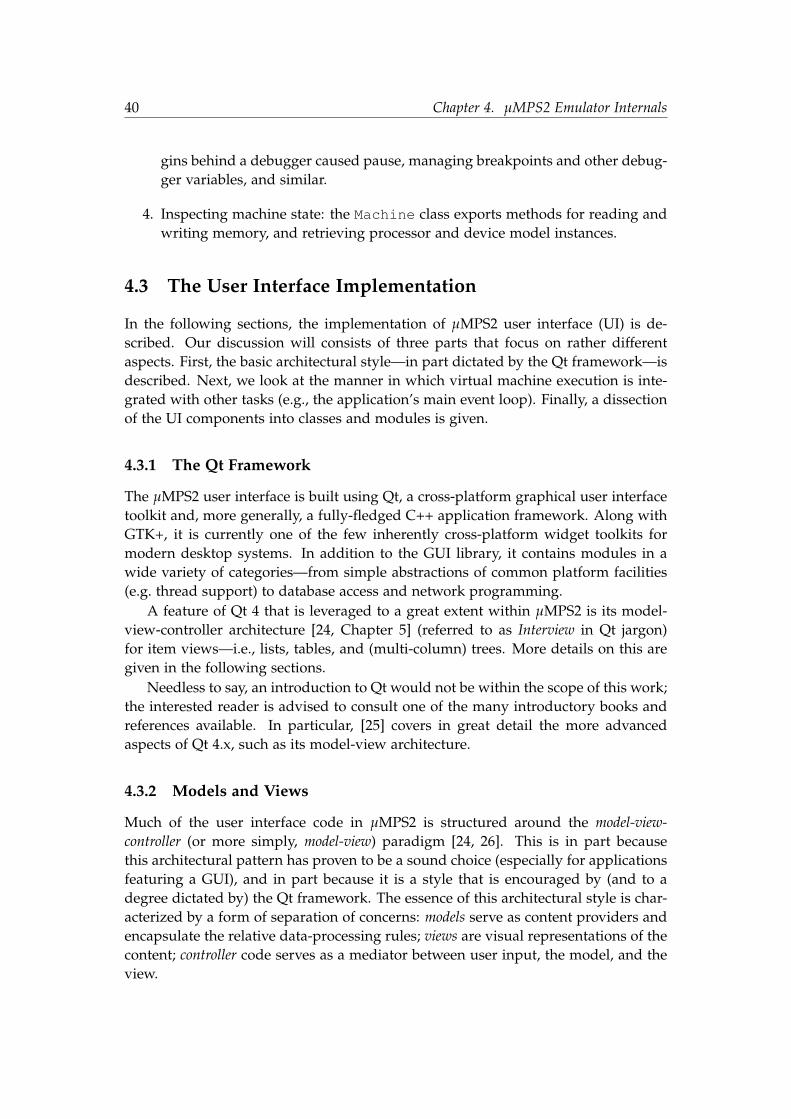
40 Chapter 4. µMPS2 Emulator Internals
gins behind a debugger caused pause, managing breakpoints and other debug-ger variables, and similar.
4. Inspecting machine state: the Machine class exports methods for reading andwriting memory, and retrieving processor and device model instances.
4.3 The User Interface Implementation
In the following sections, the implementation of µMPS2 user interface (UI) is de-scribed. Our discussion will consists of three parts that focus on rather differentaspects. First, the basic architectural style—in part dictated by the Qt framework—isdescribed. Next, we look at the manner in which virtual machine execution is inte-grated with other tasks (e.g., the application’s main event loop). Finally, a dissectionof the UI components into classes and modules is given.
4.3.1 The Qt Framework
The µMPS2 user interface is built using Qt, a cross-platform graphical user interfacetoolkit and, more generally, a fully-fledged C++ application framework. Along withGTK+, it is currently one of the few inherently cross-platform widget toolkits formodern desktop systems. In addition to the GUI library, it contains modules in awide variety of categories—from simple abstractions of common platform facilities(e.g. thread support) to database access and network programming.
A feature of Qt 4 that is leveraged to a great extent within µMPS2 is its model-view-controller architecture [24, Chapter 5] (referred to as Interview in Qt jargon)for item views—i.e., lists, tables, and (multi-column) trees. More details on this aregiven in the following sections.
Needless to say, an introduction to Qt would not be within the scope of this work;the interested reader is advised to consult one of the many introductory books andreferences available. In particular, [25] covers in great detail the more advancedaspects of Qt 4.x, such as its model-view architecture.
4.3.2 Models and Views
Much of the user interface code in µMPS2 is structured around the model-view-controller (or more simply, model-view) paradigm [24, 26]. This is in part becausethis architectural pattern has proven to be a sound choice (especially for applicationsfeaturing a GUI), and in part because it is a style that is encouraged by (and to adegree dictated by) the Qt framework. The essence of this architectural style is char-acterized by a form of separation of concerns: models serve as content providers andencapsulate the relative data-processing rules; views are visual representations of thecontent; controller code serves as a mediator between user input, the model, and theview.

4.3. The User Interface Implementation 41
There are many ways in which the model-view architecture fits the interactionbetween user interface and emulator back-end components, as shown schematicallyin figure 4.2:
• The machine-level abstractions provided as part of the core emulator API(Machine, Processor, and similar) would themselves be considered mod-els, of course. Moreover, virtually all other models are built on top of these.
• Qt defines numerous standard abstract model interfaces in its Interview frame-work. Each of these interfaces defines a set of APIs a particular data sourcemust provide for interoperability with one or more types of views. For in-stance, the QAbstractTableModel class defines an abstract model interfaceimplemented by classes that (conceptually) represent a rectangular array ofdata elements of a particular kind (numbers, strings, icons, etc.).
There are several such implementations of the Qt Interview model interfaces inµMPS2. For example, processor registers in the dockable pane of the processorwindow are rendered by a QTreeView object, one of the framework’s manyview classes; the model is, of course, not a stock Qt model class but a customimplementation of the generic tree model interface, its elements being registermnemonics and register values (see RegisterSetSnapshot). The values arein turn obtained from the Processor instance itself. We may call such classesmodel adapters.
Another notable example of a model adapter class is StoppointListModel,a Qt table model adapter used to represent breakpoint, suspect, and tracepointcollections.
• View classes include both standard Qt classes and custom ones. Stock Qt viewclasses are typically used in conjunction with the model adapter classes dis-cussed above, whereas custom view classes interact with core emulator modelsand with various auxiliary models.
4.3.3 Machine Execution
Modern graphical user interface toolkits impose on the program an event-drivenprogramming model. In most cases, this model is supported by providing a formof event loop abstraction7, which manages all low-level aspects associated with eventsources of interest to the application. In a typical program flow, suitable event han-dlers are registered for particular events, and control is handed over to the event loop.The event loop blocks until one or more of the specified events are detected—for ex-ample, those originating from the underlying window system—and then dispatches
7Slight exceptions are the Swing and AWT toolkits; rather than defining an explicit event loopconstruct, these toolkits dedicate a special thread to event polling and dispatching. The “event loop”is still present, of course, but it is completely opaque to the programmer.

42 Chapter 4. µMPS2 Emulator Internals
User Interface (Views)
Qt Model Adapter
Machine Processor
Processor
Device
Device
Processor APIMachine APIDevice API
Figure 4.2: The model-view architecture of the µMPS2 emulator.
these to applicable handlers. After all handlers have been invoked, control is re-turned to the event loop and another iteration of the cycle is started.
Due to difficulties in ensuring thread safety of their respective APIs, GUI toolkitshave traditionally been inherently single-threaded, with Qt not being an exceptionto this.8 More precisely, all user interface related processing is confined to a singlethread of execution; the thread, that is, in which the UI event loop is run. All ofthis places an important policy constraint on event handlers: to ensure proper re-sponsiveness of the UI, a handler is not expected to perform any long-running task(e.g., long-running computations or certain kind of I/O) directly. It is immediateto see that virtual machine execution in µMPS2 is, in fact, an example of such acompute-bound task. An often-used solution for this problem consists of offloadingthe computation to a separate thread or process. For the reasons stated above, thistechnique is most-appropriate for cases in which the task is not required to perform asignificant amount of manipulations on the UI itself. Another popular approach con-sists of splitting the computation into smaller parts, and schedule them for executionvia the event loop as low priority tasks; the event loop will process the tasks, one byone, whenever there are no higher priority events pending (notably, window systemevents). This latter approach is currently used in µMPS2, as the risk of concurrency-related issues was considered to significantly outweigh the slight increase of controlflow complexity.
All aspects of machine execution are handled by the DebugSession class. Inparticular, it provides emulation speed control. The effective emulation speed (that
8The difficulties, in short, stem from the inherently asynchronous nature of GUI applications. Theinterested reader is referred to [27] for a discussion on this topic.

4.3. The User Interface Implementation 43
is, the rate at which machine cycles are executed) is determined by several variableswe describe below, each of which is derived from the user-controlled speed parame-ter.
In continuous execution mode (as opposed to single-stepping mode), emulationis performed in the fashion described above: the task is performed incrementally,and in each iteration a number of machine cycles are executed; the exact numberof cycles per iteration is determined by the emulation speed setting. Idle machinecycles are properly skipped, as allowed by the underlying emulation engine. Forperceived realism, the number of skipped cycles is accounted for by a suitable pausein machine execution. As a result, an idle virtual machine is reflected in an idleemulator process.
The maximum effective rate at which machine cycles can be run is further con-trolled by the minimum delay between two successive machine cycle iterations. Again,this value is derived from the user-controlled speed setting. Incidentally, the degreeto which the emulator will be a CPU-bound process is directly related to this vari-able.
Finally, the DebugSession provides suitable notification—most importantly, toUI components—of a number of related events:
• The machine is powered on, powered off, or reset. Some UI elements are eithercreated or initialized at machine power-on completion. Examples of such ele-ments are the processor status list and device status view in the main window.Likewise, after the machine has been powered down, these elements are dis-sociated from the machine state they are representing, and thus need to bedestroyed or otherwise invalidated. Reset notification is provided since virtu-ally all visible UI elements pertaining to machine state need to be updated onthat event.
• Machine execution is suspended or resumed. Certain UI elements, such as the codeview, are only sensitive to user input and exhibit meaningful semantics whileemulation is paused. (Indeed, in the case of the code view, a “live update” ofthe widget while the machine is run would not only be distracting to the user,but it would also incur a significant deterioration of performance.)
Similarly, actions such as breakpoint insertion and removal can only be per-formed while emulation is paused. Thus, their associated user interface ele-ments (menu bar entries, context menu entries, toolbar buttons, etc.) are ren-dered sensitive (i.e., the elements are “enabled”) if and only if the machine isstopped.
• An iteration of machine cycles is completed. Some machine state views updatetheir contents even while emulation is in progress. Since updates on each cyclewould be unfeasible, the refresh is instead triggered by this event. The numberof cycles between each update is thus dependent on the user’s emulation speedsetting.

44 Chapter 4. µMPS2 Emulator Internals
Elements that support this form of live updating include processor status en-tries, processor register views, traced memory regions, and the device statusview. Of course, displayed machine state is guaranteed to be “consistent” (thatis, reflect actual state values) only while the machine is stopped.
Notification is provided using Qt’s signaling mechanism; for instance, the machinereset event is represented by the MachineReset signal (see debug_session.h)and is intercepted by any UI component that need to act on this event.
4.3.4 Class and Module Overview
After the above overview of architectural aspects of the µMPS2 front-end, what fol-lows is a fairly complete outline of the UI code base. Rather than listing classesor modules in some arbitrary order, we systematically group classes by their userinterface affinity, starting from top level windows:
• Main window. The main window is represented by the MonitorWindow class.9
While most sub-panes in this window are implemented by separate classes, theclass alone manages a fair number of different aspects: its tab based layout, theQAction based menu and toolbar interface, auxiliary window visibility, andmany other ancillary tasks.
The greater part of the main window is occupied by its tabbed sections:
– Machine overview tab. This tab is implemented by MachineConfigView, asimple composite widget that displays machine parameters in a table-likelayout.
– Processor tab. This tab is split into an upper half, which contains the pro-cessor status list, and a lower one, which contains the breakpoint list. Theeffective tab area allocated to the two child widgets is user controllableand is managed by the QSplitter widget.The underlying model class for the processor status list (or, more pre-cisely, table) is ProcessorListModel; the latter is a direct subclass ofQt’s QAbstractTableModel abstract class, which defines an interfaceexpected to be provided by all table model classes within the Interviewframework. The view itself is rendered by the stock QTableView class.An entirely analogous separation of concerns—those of a model fromthose of a view—applies for the breakpoint, suspect, and tracepoint lists.In this case, the model is provided by the StoppointListModel class.
– Memory tab. The memory tab contains the suspect list and a traced re-gion browser. The former is completely analogous to the breakpoint listdiscussed above.
9As a general guideline, there is a direct correspondence between a class and a (single) translationunit, with a slight difference in naming convention between the two. An example will suffice: theclass TerminalView is associated with the class implementation file terminal_view.cc and thecorresponding header file terminal_view.h.

4.3. The User Interface Implementation 45
As discussed in Section 3.4.5, multiple display types are supported fortraced memory regions. The associations between traced region and theuser’s preferred display type is managed by the TraceBrowser class.Display-wise, TraceBrowser is a composite widget comprising the tra-cepoint list, the display type drop-down list (frequently called a “combobox”), and the memory view itself.The ASCII rendition of the memory is rather simple (see the AsciiViewclass in trace_brower.h) and should not require explanation. As ex-pected, considerably more complex is the editable hex-dump view imple-mentation, given by HexView. By subclassing QPlainTextEdit, Qt’splain text visualization and editing widget, it leverages the widget’s ex-tensive text display and manipulation facilities (e.g., text highlighting andscrolling support). At the same time, the hex view requires customizedkey and mouse-based navigation within the grid-like display. Similarly,since the memory itself acts as a “backing store” for its contents, editingrequires special handling. Support for these is implemented by overridingcertain QPlainTextEdit methods (see the HexView::keyPressEventmethod, for an example).
– Device status. Again, the same split between the view and underlyingmodel applies (as in the case of the processor list, for instance). In thiscase, the implementation (DeviceTreeModel) is considerably more com-plex, since the model’s data retrieval mechanisms must support a hierar-chical structure, as specified by the QAbstractItemModel interface.
• Processor window. Top-level processor windows (ProcessorWindow) feature acentral content, consisting of the code view and processor status information,and certain secondary panes. At the user’s preference, these secondary win-dows can either be positioned inside the processor window around its centralcontent or made into top-level windows. Secondary windows are implementedusing Qt’s dock widgets (see QMainWindow and QDockWidget). Details aboutthe main elements follow:
– Code view. The code view (CodeView) is another subclass of Qt’s plaintext display and editing widget, QPlainTextEdit. The implementationprovides a custom margin widget (see CodeViewMargin) onto whichmemory addresses, breakpoint markers, and the program counter markerare rendered (see CodeView::paintMargin). Breakpoint insertion andremoval is supported by the margin by overriding mouse event handlers.
– Register view. The register view is one of the two “dockable” widgetsbelonging to the processor window. The top-level widget itself, namelyRegisterSetWidget, manages the selection of register value represen-tation format (e.g., binary, decimal, etc.).Register items (that is, mnemonic and corresponding value pairs) them-selves are rendered by the TreeView widget. The underlying data model

46 Chapter 4. µMPS2 Emulator Internals
is provided by RegisterSetSnapshot—yet another example of a QtInterview abstract item model realization.Recall that the register view is one of the elements periodically updatedeven while the machine is running. In order to support this reasonablyefficiently, RegisterSetSnapshot implements a form of “lazy” updatenotifications. Register values fetched from the CPU are cached on eachrefresh cycle, so that on the following cycle new values can be comparedwith cached ones, and the view can as a result be only notified aboutmodified values.
– TLB view. This is essentially similar to the register view described above(see the TLBModel class).
• Terminal window. Terminal windows are instances of TerminalWindow; theactual widget implementing a text terminal is TerminalView—another sub-class of QPlainTextEdit. Where needed, the TerminalView class overridesits superclass method implementations to simulate the behavior of a real textterminal (see TerminalView::keyPressEvent, for example).
4.4 µMPS2 Object File Support Tools
For reasons that have already been elaborated (see Section 3.5.3), µMPS2 includessupport for a greatly streamlined executable file format. Two object file-relatedtools are currently available: umps2-elf2umps converts ELF relocatable objectsand executables to µMPS BIOS images and .aout/.core executables, respectively;umps2-objdump is an analogue of the well known objdump utility, albeit less so-phisticated. These tools are provided as stand-alone executables—rather than, say,being integrated into the GUI environment—the reason being that they are typicallyexpected to be used as part of an automated build workflow.
Among executable file formats, .aout is exceptionally simple. For reasons ofspace, its specification is not replicated here; the reader is referred to [11]. In the restof this section, however, the most important aspects of the ELF to .aout conversionare addressed, including some rather subtle points.
4.4.1 ELF to .aout Conversion
The ELF to .aout conversion code (see elf2umps.cc) is fundamentally not verycomplex. (Needless to say, a working understanding of the conversion process de-mands at least basic familiarity with the ELF format, for which we refer the reader to[28] or [29]). Essentially, ELF input sections10 are scanned, one by one, and data from
10There is some terminological inconsistency across object file formats regarding the interpretationof “section” and “segment”. While these two words are often used interchangeably, in the context ofthe ELF format they denote different concepts. For reasons mostly based on efficiency and flexibility,ELF supports a dual view of an object file. First, a file may be treated as a collection of sections—thatis, units containing program data or metadata of a particular kind. Thus, code, data, read-only data,

4.4. µMPS2 Object File Support Tools 47
“loadable” sections is copied to the corresponding segment of the .aout executable(see the elf2aout function). The simplicity stems from an important assumptionabout the input ELF executable; namely, that its memory layout (the segment layout)matches the desired memory layout of the corresponding .aout executable. This re-quirement is satisfied by providing suitable directives to the linker (ld), in the formof a linker script. In short, a linker script defines the manner in which sections fromone or more input object files are combined into sections of the output file. In doingso, the script defines the memory layout of the output file.
We see that in effect, an .aout executable is obtained via a cooperation of thelinker—driven by a linker script—and the umps2-elf2umps utility itself. We wishto elaborate somewhat on the former, since the linker script command language mayadmittedly seem arcane to the uninitiated. (For a detailed description of the linkercommand language accepted by the GNU linker, the reader is referred to its officialdocumentation. Barely enough syntax is introduced here to render the discussioncomprehensible.)
Listing 4.2 shows a linker script suitable for .aout executables. Any linker scriptsconsists of a series of commands, each of which controls a particular aspect of thelinking process. An example is the ENTRY command on line 2, which defines theprogram’s entry point.
The PHDRS command (lines 4-8) lists the program headers (segments) the outputexecutable should contain. Those will correspond to the .text and .data segments inthe final .aout executable.
The rest of the script is taken by the compound SECTIONS command. Of allcommands allowed inside SECTIONS, two types are encountered in the script below:
• Symbol assignments: Symbols may be defined and assigned arbitrary valuesusing linker scripts. These symbols will appear in the resulting object’s symboltable, just like those generated by the assembler. For example, on line 34 thesymbol _gp is defined.
As a special case, the symbol name ‘.’, called the output location counter, denotesthe memory address the next portion of the output is normally associated with.
• Output section descriptions: These commands describe how input sections shouldbe merged to form output sections. The full syntax of an output section de-scription command is rather complicated, and since most occurrences do notneed nor use most of the features, it suffices for our needs to examine the firstsuch command appearing in the script below (lines 14-18). The .text iden-tifier outside of the curly braces is the output section name. Inside the curlybraces, the most important command that may appear is an input section de-scription (line 17), which causes selected input sections from one or more inputfiles to be copied to the output section in question (in this case, .text).
relocation information, debugging information, etc. all belong to different sections of the file. The fileis endowed with this structure to support linking, in addition to tools such as debuggers. On the otherhand, an ELF executable file may be viewed as a set of segments that define its memory layout. Thissecond view exists to support the run-time system (loaders) efficiently.

48 Chapter 4. µMPS2 Emulator Internals
Each input section description includes an input file name followed by a list ofsection names in parenthesis, both of which can use Bourne shell-like wildcardpatterns. The command from our example, namely *(.text .text.*), in-structs the linker to merge into the current output section all sections matchingthe names .text or .text.* from any input file.
After this brief demystification, it is now hopefully easy to see how the mentionedlinker script results in a memory layout that complies with the µMPS .aout formatrequirements. The base address of the .aout .text area is 0x8000.0000; to accom-modate the 90-byte .aout header, the sections comprising the text segment of the ELFexecutable start at 0x8000.00B0 (line 13). The text segment contains all code andread-only data sections. The data segment starts on the first page-aligned addressafter the text (line 27); it contains the .data sections, the global offset table (GOT)[28], the “small data sections”, and similar.
Listing 4.2: A linker script for .aout executables.
1 OUTPUT_ARCH(mips)2 ENTRY(__start)34 PHDRS5 {6 text PT_LOAD FILEHDR PHDRS;7 data PT_LOAD;8 }9
10 SECTIONS11 {12 /* Text segment */13 . = 0x800000B0;14 .text :15 {16 _ftext = . ;17 *(.text .text.*)18 } :text =019 PROVIDE (_etext = .);2021 .rodata : { *(.rodata .rodata.*) } :text22 .rodata1 : { *(.rodata1) } :text23 .sdata2 : { *(.sdata2 .sdata2.*) } :text24 .sbss2 : { *(.sbss2 .sbss2.*) } :text2526 /* Data segment */27 . = ALIGN(0x1000);28 .data :29 {30 _fdata = . ;31 *(.data .data.*)32 } :data

4.4. µMPS2 Object File Support Tools 49
33 .data1 : { *(.data1) } :data34 _gp = ALIGN(16) + 0x7ff0;35 .got : { *(.got.plt) *(.got) } :data36 .sdata : { *(.sdata .sdata.*) } :data37 .lit8 : { *(.lit8) } :data38 .lit4 : { *(.lit4) } :data39 _edata = .;4041 __bss_start = .;42 _fbss = .;43 .sbss :44 {45 PROVIDE (__sbss_start = .);46 *(.sbss .sbss.*)47 *(.scommon)48 PROVIDE (__sbss_end = .);49 } :data50 .bss :51 {52 *(.bss .bss.*)53 *(COMMON)54 . = ALIGN(32 / 8);55 } :data5657 . = ALIGN(32 / 8);58 _end = .;59 PROVIDE (end = .);6061 /DISCARD/ : { *(.reginfo) }62 }


Chapter 5
Conclusions
The µMPS system, which formed the basis for the work that has been described inthis thesis, was designed to fulfill the need for an approachable and at the same timereasonably realistic computer architecture and accompanying emulator, tailored foruse in computer science education.
The most important way µMPS2 improves upon its predecessor is through thearchitecture update. By including multiprocessor support, µMPS2 renders the archi-tecture considerably more relevant in an era in which multi-core designs are becom-ing ever more prevalent. It is hoped that, by virtue of being exceptionally simpleimplementation-wise, the system will be able to adapt equally promptly to futurehardware trends.
The other major overhaul in µMPS2 is in the emulator’s front-end, which (it ishoped) has resulted in notable usability improvements. The µMPS2 user interfaceenvironment is currently unique in its category in providing intrinsic multiprocessormonitoring and debugging support.
5.1 Suggestions for Further Experiments
Some suggestions for possible extensions to µMPS are given below. Needless tosay, the list is not in any case exhaustive, nor are those necessarily the most viabledirections for the project. As many users are bound to discover, the current systemis surely open to many smaller, incremental, improvements.
5.1.1 Detailed Simulation
A direction arguably worth pursuing with µMPS concerns more detailed and realis-tic simulation models, particularly with regard to the memory system. Indeed, that(centralized or distributed) shared memory architectures will have an ever more pro-found impact on software design in the near future—both for operating systems andend-user applications—is suggested by current trends, and is likely not a recklessprediction.
51

52 Chapter 5. Conclusions
The simple CPU model in µMPS2 could be combined with realistic memorysystem models, including MESI-based coherent caches, cache coherent NUMA, andsimilar. Of course, it would be most desirable to continue to support the currentlyused simpler emulation model, for cases where quick execution is a priority overrealism.1
5.1.2 Emulator Scalability
The emulator implementation described in Chapter 4 has multiple virtues, includingsimplicity of implementation and a fully deterministic execution model. Unfortu-nately, the implementation in its current form is inherently non scalable beyond asmall number of processors, as it uses a single thread of execution to emulate multi-ple virtual processors in lockstep fashion. A currently investigated alternative designconsists of exploiting thread-level parallelism at the host level, the key idea behindthis design being that various components comprising a computer system are to agreat extent autonomous—that is, largely independent of each other.
In the proposed experimental implementation, a dedicated thread is assignedto each emulated processor; a separate thread executes the emulator event loop,which handles event scheduling (e.g., expiration of various hardware timers and I/Ocompletion) and dispatching to event handlers. Long-running blocking operationsmay be delegated to special worker threads, allocated from a thread pool.
One consequence of introducing this form of thread-based concurrency into theemulator is that the architecture’s intuitive, strictly ordered memory consistencymodel (see [31] for a discussion of memory consistency models in general, and or-dering semantics in particular) must in all likelihood be sacrificed. Indeed, to havereasonable chance of gaining an advantage from the introduced parallelism, the em-ulator cannot guarantee ordering semantics stricter than those of the underlyinghost’s memory system. A consistency model must then be defined for the emulatedarchitecture whose semantics correspond to the weakest model among the supportedhost architectures. Next, a set of memory barrier instructions must be provided,whose implementation will naturally depend on the particular host architecture.
Finally, changes are required in virtual time management. In the single threadedimplementation virtual processors run in lockstep manner and single processorscycles correspond to ticks of the centrally maintained “time-of-day” clock. This clockis maintained by the emulator and has no bearing on host time. In a multithreadedimplementation where, at least to some extent, each virtual CPU runs independentlyof the rest of the system this is not feasible anymore. Instead, it is desirable to basevirtual time bookkeeping on one of the high resolution clock sources provided bythe host system.
1For reference, a system that supports varying degrees of simulation speed and detail, from fastexecution modes based on dynamic translation techniques to detailed microarchitecture models, isSimOS [30].

5.1. Suggestions for Further Experiments 53
5.1.3 An Operating System for µMPS2
All testing has so far relied on simple, mostly ad hoc “operating systems”. A rea-sonably featured, SMP-capable operating systems would undoubtedly prove veryuseful during emulator development (e.g. for tasks such as performance evaluationsor regression tests). One could either develop such an OS from scratch, or choose toport one of the lightweight open source operating systems to µMPS2. Both optionspromise an educationally rewarding experience.


Appendix A
µMPS2 Architecture Revision
This appendix presents the new hardware and firmware features of µMPS2. Theprominent new features center around multiprocessor support: initialization andcontrol of multiple processors, interrupt management in a multiprocessor environ-ment, new processor instructions for concurrency support and ROM services. Wher-ever possible, architectural additions were designed to be unobtrusive with regardto legacy software and programmers not striving to support software features (suchas SMP support) that require them.
A.1 Machine Control Registers
µMPS2 provides the programmer with explicit control over the power states of CPUsand the machine itself. This is accomplished through the Machine Control register set,shown in Table A.1.
The NCPUs register stores the number of processors in the system; ResetCPU,BootPC, BootSP, HaltCPU control the processors power state and start-up (state onreset); finally, the Power register is used to power off the machine.
Table A.1: Machine control registers address map.
Address Register Type0x1000.0500 NCPUs Read Only0x1000.0504 ResetCPU Write Only0x1000.0508 BootPC Read/Write0x1000.050c BootSP Read/Write0x1000.0510 HaltCPU Write Only0x1000.0514 Power Write Only
55

56 Appendix A. µMPS2 Architecture Revision
A.1.1 Processor Power States
At each point in time a processor in µMPS2 can be in one of several power states,which define whether it is currently executing instructions and its responsiveness toexternal events (interrupt, reset and halt signals).
µMPS2 defines three power states:
• Halted: This state represents the lowest power state. A CPU in this state willonly respond to a reset signal, which transitions the CPU into the Running state,causing it to start executing instructions.
A CPU transitions into this state when its halt signal is asserted, which is trig-gered by writing the CPU ID into the HaltCPU register. The CPU does notmaintain any architecturally visible state (e.g. CPU registers) in this powerstate.
• Running: This state represents the normal operating state of the CPU. A CPU inthis state responds to both interrupts and halt/reset signals. A CPU transitionsinto this state as a result of external events.
• Idle: A CPU in this state operates in reduced-power mode. The CPU stopsexecuting instructions when it transitions into this state, but it stays responsiveto all external events. A CPU transitions into this state by executing the waitinstruction. The CPU maintains all architecturally visible state in this powerstate. This state is also often referred to as standby.
Figure A.1 recaps the possible transitions between power states.
Running
Halted Idle
Reset
HaltW
aitReset, Interrupt
Halt
Figure A.1: Processor power states.
A.1.2 Processor Initialization
After a machine reset, only processor 0 is automatically started (i.e. in the Runningpower state). Explicit start-up (reset) commands must be issued to start the other pro-cessors. A secondary processor starts executing when it receives a reset signal. Thisis accomplished by writing the processor ID into the Reset register. The processor

A.2. New and Revised CP0 Registers 57
starts executing at the location specified by the BootPC register, with the processor’ssp register set to the value provided by the BootSP register. All other aspects of theprocessor state at reset time are as described in [11].
As described in Section A.5, the BIOS and libumps library provide a more con-venient way to initialize a processor.
A.1.3 Powering Off the Machine
Machine power off is initiated by writing the magic value 0x0FF into the write-onlyPower register. The power down completes after a non-negligible delay.
A.2 New and Revised CP0 Registers
Among the software-visible changes introduced with µMPS2 some are within thesystem control coprocessor’s (CP0) register space. Table A.2 lists CP0 registers alongwith compatibility notes. The following sections describe each change in detail andmotivate their introduction.
Table A.2: CP0 registers.
Mnemonic Number Compatibility NotesIndex 0 -Random 1 -EntryLo 2 -BadVAddr 8 -Timer 9 New in µMPS2EntryHi 10 -Status 12 A new read/writable TE field has been added
(see Figure A.2).Cause 13 IP[0] and IP[1] are no longer writable.EPC 14 -PRID 15 This read-only register now stores the proces-
sor ID instead of CPU model information.
A.2.1 PRID Register
In µMPS2 the PRID register contains the processor identifier (CPUID), which is aunique integer assigned to a processor at power up that does not change afterwards.
The read-only PRID register has been used in MIPS CPUs as a CPU model identi-fier. In contemporary MIPS processors, it contains a field that identifies the instruc-

58 Appendix A. µMPS2 Architecture Revision
Table A.3: Interrupt line assignment in µMPS2.
Interrupt Line Assignment0 IPI1 Local Interval Timer2 Bus (Interval Timer)3 Disk Devices4 Tape Devices5 Network (Ethernet) Devices6 Printer Devices7 Terminal Devices
tion set architecture, along with manufacturer dependent fields. Since such infor-mation is only plausibly useful to legacy MIPS software which interpret it (typicallyas part of the hardware probing process) and µMPS implements a fixed variant ofthe MIPS I ISA, the above redefinition of the PRID register is very unlikely to causecompatibility problems.
A.2.2 The On-CPU Interval Timer
µMPS2 provides a per-CPU interval timer (referred to as the local timer in this section)that runs at the processor’s clock rate and is in all respects similar to the externalinterval timer device. Unlike the external interval timer, the local timer can be dis-abled (default setting). Whether the local timer is enabled or not is determined bythe Status.TE (Timer Enable) bit. When Status.TE = 0, the local timer will notgenerate interrupts. Note, however, that it is implementation dependent whetherthe timer will continue to run when Status.TE = 0. If the local timer is enabled(Status.TE = 1), it will continue to run and generate interrupts even when theprocessor enters standby mode (see Section A.4.2).
Interrupts from he local timer are assigned to interrupt line 1 (see Table A.3). TheCP0 Timer register represents the programmer’s interface to the local interval timer.Pending interrupts from the local timer are acknowledged by writing a new valueinto the Timer register.
The local interval timer will most likely only be of use to operating systems withmultiprocessor support, where the local timer can be used for scheduling purposes.Since interrupts from the external timer source can only be delivered to a single CPUat a time, this can potentially avoid the overhead of interprocessor interrupts.

A.3. Multiprocessor Interrupt Control 59
A.2.3 Status Register
The Status register contains a single new field, TE, that enables/disables the on-CPU timer.
01234581522242526272831
CU TE
VM
oV
Mp
VM
c
BEV IM
KU
oIE
oK
Up
IEp
KU
cIE
c
Figure A.2: The Status CP0 register.
A.2.4 Backward Compatibility Notes
Two of the described modifications of the CP0 register space potentially compro-mise backward compatibility with existing software. As already noted above, theredefinition of the PRID register is unlikely to cause compatibility problems.
Interrupt lines 0 and 1, previously reserved for software interrupts, are reas-signed to inter-processor interrupts and the on-CPU timer, respectively. Programsthat relied on this older form of software generated interrupts will find inter-processorinterrupts (described in a separate section) to be a relatively straightforward replace-ment.
A.3 Multiprocessor Interrupt Control
The new interrupt delivery subsystem in µMPS2 is designed to support SMP-capableoperating systems. It allows the creation of elaborate interrupt affinity and/or bal-ancing schemes and provides a simple inter-processor interrupt (IPI) mechanism. Notethat the default settings of the registers described in this section provide for fullbackward compatibility with uniprocessor systems. Thus, the register-level interfacedescribed here will only be of concern to programmers willing to support multipro-cessor systems.
Conceptually, the multiprocessor interrupt controller is comprised of the follow-ing units:
• A centralized programmable unit called the Interrupt Router that distributesinterrupts from peripheral interrupt sources to selected processors.
• One or more CPU Interface units that receive interrupts from the InterruptRouter and control the transmission and reception of IPI messages.
A.3.1 Interrupt Distribution
For systems under heavy I/O load, it is often desirable to distribute interrupts acrossmultiple processors. µMPS2 allows the programmer to specify interrupt routing

60 Appendix A. µMPS2 Architecture Revision
parameters per interrupt source. Routing parameters are stored in a set of pro-grammable registers, called the Interrupt Routing Table (IRT). Each IRT entry controlsinterrupt delivery for a single interrupt source.
Two distribution policies are supported:
• Static: The interrupt is delivered to a preselected processor.
• Dynamic: The interrupt is delivered to the processor executing the lowest pri-ority task.
0152831
RP Destination
Figure A.3: IRT entry format.
Each IRT entry register (see Figure A.3) consists of the following fields:
• RP (bit 28): Specifies the routing policy. The field is interpreted as follows:
0 (Static) The interrupt is delivered to the processor specified in theDestination field. The Destination field is interpretedas a CPU ID.
1 (Dynamic) The Destination field is interpreted as a CPU mask, wherebit i of Destination[15:0] corresponds to CPU ID i. Theinterrupt is delivered to the processor executing the lowest pri-ority task among all contestants selected by the mask. In caseof a tie, an implementation-defined arbitration mechanism isused to resolve it.The above mechanism relies on the operating system to updateat appropriate times the execution priority of all selected pro-cessors. This is accompished by programming the Task Priority(TPR) register, located in the interrupt controller CPU interfaceregister bank (see section A.3.2).
• Destination (bits 0-15): Used to specify the interrupt target processor(s).See the description of the RP field for details on how this field is interpreted.
As shown in figure A.4, the IRT has 48 entries. Interrupt routing information fordevice device j, attached to interrupt line i, is recorded in entry (i − 2)× 8 + j.
A.3.2 CPU Interface Registers
The CPU Interface registers, shown in Table A.4, represent the per-processor com-ponent of the multiprocessor interrupt controller register-level interface. Althoughmultiple banks (one per CPU) of these registers are provided, they all share the sameaddress map.

A.3. Multiprocessor Interrupt Control 61
0x1000.03BC Interrupt 7:7 Routing Entry
. . . . . .
0x1000.0340 Interrupt 4:0 Routing Entry
0x1000.033C Interrupt 3:7 Routing Entry
. . . . . .
0x1000.0324 Interrupt 3:1 Routing Entry
0x1000.0320 Interrupt 3:0 Routing Entry
Interrupt line 3
routing information
. . .
0x1000.0300 Interrupt 2:0 Routing Entry
Figure A.4: IRT register address map.
Table A.4: Interrupt controller processor interface register map.
Address Register Type0x1000.0400 Inbox Read/Write0x1000.0404 Outbox Write Only0x1000.0408 TPR Read/Write0x1000.040c BIOSReserved1 Read/Write0x1000.0410 BIOSReserved2 Read/Write
The Inbox and Outbox registers are used for inter-processor interrupts and theiruse is detailed in the next section.
The Taks Priority (TPR) register, shown in Figure A.5, is used by the InterruptRouter in the priority based arbitration scheme. The TPR.Priority field allowsfor 16 priority levels, with 0 and 15 representing the highest and lowest prioritiesrespectively.
0331
Priority
Figure A.5: The TPR register.
The two registers labelled as BIOS Reserved are provided for the convenience ofthe ROM based exception handling code.
A.3.3 Inter-processor Interrupts (IPIs)
An inter-processor interrupt (IPI) represents a form of inter-processor signaling mech-anism used by a processor to request the attention of another processor. IPIs are

62 Appendix A. µMPS2 Architecture Revision
commonly used by operating systems for issuing rescheduling requests, maintain-ing TLB consistency, and any other task which requires one processor to request theattention of another.
In µMPS2, multiple IPIs may be pending at the same time for a given processor;there is, however, a limit of one pending IPI per originating processor. Only one pendingIPI may be acknowledged at a time. There is no built-in delivery status notificationmechanism.
An arbitrary 8-bit data field (message) can be carried with each IPI. This feature isprovided solely for software convenience and has no side effects on the IPI deliverysubsystem.
The system maintains IPI delivery order. IPI messages are always retrieved in theorder they were received by the CPU interface.
Issuing IPIs
An IPI is issued by writing a correctly formatted IPI command to the Outbox regis-ter, shown in Figure A.6.
0782331
Recipients Message
Figure A.6: The Outbox register.
The fields in the Outbox register are defined as follows:
• Message (bits 0-7): The message to be delivered.
• Recipients (bits 8-23): Selects the recipients of the IPI. The field is inter-preted as a CPU mask: the IPI is delivered to processor i if Recipients[i] ison.
IPI Receipt and Acknowledgement
Information on the currently pending IPI is stored in the Inbox register (shown inFigure A.7) which contains the following fields:
• Message (bits 0-7): The message to be delivered.
• Origin (bits 8-11): The processor ID of the originating processor.
0781131
Origin Message
Figure A.7: The Inbox register.
An IPI is acknowledged by writing to the Inbox register. The written value isignored.

A.4. New Instructions 63
A.4 New Instructions
A.4.1 Compare and Swap (CAS)
056101115162021252631
0 rs rt rd 0 cas (001011b)
Format:cas rd, rs, rt
Description:The cas instruction performs an atomic read-modify-write operation on synchroniz-able memory locations. The contents of the word at the memory location specifiedby the GPR rs is compared with GPR rt. If the values are equal, the content ofGPR rd is stored at the memory location specified by rs and 1 is written into rd.Otherwise, 0 is written into rd and no store occurs.
The above read-modify-write sequence is guaranteed to be atomic by ensuringthat no intervening operation on a conflicting memory location is performed by thememory system. The following pseudocode illustrates the operation of the casinstruction:
atomic {if (MEM[rs] == GPR[rt]) {
MEM[rs] = GPR[rd];GPR[rd] = 1;
} else {GPR[rd] = 0;
}}
The set of synchronizable memory locations in µMPS2 coincides with physical RAMlocations. For all other locations (e.g. the I/O address space) cas will uncondition-ally fail.
Exceptions:TLBS, Mod, DBE, AdES
libumps interface:int CAS(uint32_t *atomic, uint32_t ov, uint32_t nv)
This function atomically sets the word pointed to by atomic to nv if the currentvalue of the word is ov. It returns 1 to indicate a successful update and 0 otherwise.

64 Appendix A. µMPS2 Architecture Revision
A.4.2 Wait for Event (WAIT)
05624252631
010000 CO 0 wait (100000b)
Format:wait
Description:The wait instruction causes the processor to enter standby mode. The processorresumes execution when an external event (reset or interrupt) is signaled to theprocessor. Note that it is irrelevant whether the signaled interrupt is enabled or not.If the processor resumes execution as a result of an enabled interrupt and Status.IEcis on, the (interrupt) exception is considered to have occurred at the instructionfollowing the wait instruction.
Exceptions:CpU
libumps interface:void WAIT(void)
A.5 BIOS Services
The BIOS ROM code supplied with µMPS provides convenient low-level services anOS can rely on or build upon. Most importantly, the general and TLB-refill exceptionentry points lie in the ROM space. In µMPS2, the BIOS exception handling codehas been made reentrant with regard to multiple processors. To ensure reentrancy,separate Old and New Processor State Areas must be provided for each processor.
A new BIOS service has been added to hide most of the complexities of processorstartup and initialization of BIOS-related processor data structures. It is exposed bythe libumps library function INITCPU:
void INITCPU(uint32_t cpuid, state_t *start_state, state_t *state_areas);
This function initiates a reset of the processor specified by cpuid, causing it tostart execution at a preselected startup entry point in the ROM. The startup rou-tine initializes the BIOS data structures related to the processor (most importantly, itrecords the address of the New/Old State areas, given in the state_areas parame-ter). Finally, it loads the processor state from the supplied start_state parameter.

A.6. Device Register Memory Map 65
A.6 Device Register Memory Map
0x1000.0000
0x1000.0028
0x1000.003C
0x1000.0050
0x1000.0060
0x1000.00C0
0x1000.00D0
0x1000.02C0
0x1000.02D0
0x1000.02FC
0x1000.0300
0x1000.03C0
0x1000.0400
0x1000.0414
0x1000.0500
Bus Register Area
Installed Devices Bitmap
Interrupting Devices Bitmap
Interrupt Line 3, Device 0Device Register
Interrupt Line 3, Device 1Device Register
Interrupt Line 3, Device 7Device Register
Interrupt Line 4, Device 0Device Register
Interrupt Line 7, Device 7Device Register
Reserved
Interrupt Routing Table
Reserved
CPU Interface Registers
Reserved
Machine Control Registers
Bus Error0x1000.0518
Figure A.8: Device register memory map.


Appendix B
Machine Configuration Format
A complete description of the µMPS2 machine configuration format is given below,in the form of a JSON Schema [32]. It is hoped that the schema is reasonably self-documenting—at least to the extent a document of that type can be. Notes have beenadded in the few places where further explanation was deemed necessary.
Listing B.1: A JSON Schema for the µMPS2 machine configuration format.
1 {2 "type" : "object",3 "properties" : {4 "num-processors" : {5 "type" : "number",6 "description" : "Number of processors",7 "required" : false,8 "minimum" : 1,9 "maximum" : 16,
10 "default" : 111 },12 "clock-rate" : {13 "type" : "number",14 "description" : "Processor/bus clock rate",15 "required" : false,16 "minimum" : 1,17 "maximum" : 99,18 "default" : 119 },20 "tlb-size" : {21 "type" : "number",22 "description" : "Translation lookaside buffer size",23 "required" : false,24 "minimum" : 4,25 "maximum" : 64,26 "default" : 1627 },28 "num-ram-frames" : {
67

68 Appendix B. Machine Configuration Format
29 "type" : "number",30 "description" : "Number of RAM frames",31 "required" : false,32 "minimum" : 8,33 "maximum" : 512,34 "default" : 6435 },36 "bootstrap-rom" : {37 "type" : "string",38 "description" : "Bootstrap ROM image file name",39 "required" : false,
40 "default" : default bootstrap ROM module 1
41 },42 "execution-rom" : {43 "type" : "string",44 "description" : "Execution ROM image file name",45 "required" : false,
46 "default" : default execution ROM module 2
47 },48 "boot" : {49 "type" : "object",50 "properties" : {51 "core-file" : {52 "type" : "string",53 "description" : "Core file name",54 "required" : false,55 "default" : "kernel.core.umps"56 },57 "load-core-file" : {58 "type" : "boolean",59 "description" : "Load core file on startup",60 "required" : false,61 "default" : true62 }63 }64 },65 "devices" : {66 "type" : "object",67 "description" : "Installed devices",68 "patternProperties" : {
69 "(disk|tape|printer|terminal)[0-7]" : { 3
70 "type" : "object",71 "properties" : {72 "file" : {73 "type" : "string",74 "description" : "Device file",75 "required" : true76 },77 "enabled" : {

69
78 "type" : "boolean",79 "description" : "Enable this device",80 "required" : true81 }82 }83 },
84 "eth[0-7]" : { 3
85 "type" : "object",86 "properties" : {87 "file" : {88 "type" : "string",89 "description" : "Device file",90 "required" : true91 },92 "enabled" : {93 "type" : "boolean",94 "description" : "Enable this device",95 "required" : true96 },97 "address" : {98 "type" : "string",99 "description" : "MAC address",
100 "required" : false,101 "pattern" :102 "[A-Fa-f0-9][02468aAcCeE](:([A-Fa-f0-9]{2})){5}"103 }104 }105 }106 }107 }108 }109 }
1 The default bootstrap ROM image is coreboot.rom.umps, included in thedistribution and installed under a configuration-dependent location (typically/usr/share/umps2 or /usr/local/share/umps2).
2 The default bootstrap ROM image is exec.rom.umps, distributed with µMPS2and installed under a configuration-dependent location.
3 For example, the object corresponding to the first terminal device is indexed bythe key terminal0 and the one corresponding to the second network deviceis indexed by eth1. Note that all mappings are optional.


Bibliography
[1] M. Goldweber, R. Davoli, and M. Morsiani, “The Kaya OS project and the µMPShardware emulator,” SIGCSE Bull., vol. 37, pp. 49–53, June 2005.
[2] M. Goldweber, R. Davoli, and T. Jonjic, “Supporting operating systems projectsusing the µMPS2 hardware simulator,” in Proceedings of the 17th ACM annualconference on Innovation and technology in computer science education, ITiCSE 2012,(New York, NY, USA), pp. 63–68, ACM, 2012.
[3] R. H. Austing, B. H. Barnes, D. T. Bonnette, G. L. Engel, and G. Stokes, “Cur-riculum ’78: Recommendations for the Undergraduate Program in ComputerScience,” Commun. ACM, vol. 22, pp. 147–166, March 1979.
[4] L. Cassel, A. Clements, G. Davies, M. Guzdial, R. McCauley, A. McGettrick,R. Sloan, L. Snyder, P. Tymann, and B. Weide, “Computer science curriculum2008: An interim revision of cs 2001,” 2008.
[5] J. Lions, Lions’ commentary on UNIX 6th edition with source code. San Jose, CA,USA: Peer-to-Peer Communications, Inc., 1996.
[6] M. J. Bach, The Design of the UNIX Operating System. Upper Saddle River, NJ,USA: Prentice-Hall, Inc., 1986.
[7] A. S. Tanenbaum and A. S. Woodhull, Operating Systems Design and Implementa-tion (3rd Edition). Upper Saddle River, NJ, USA: Prentice-Hall, Inc., 2005.
[8] J. Parker, R. Cupper, C. Kelemen, D. Molnar, and G. Scragg, “Laboratories inthe Computer Science Curriculum,” Computer Science Education, vol. 1, no. 3,pp. 205–221, 1990.
[9] N. Titterton and M. Clancy, “Adding some lab time is good, adding more mustbe better: the benefits and barriers to lab-centric courses,” in proceedings of the2007 International Conference on Frontiers in Education: Computer Science and Com-puter Engineering, Las Vegas, NV, 2007.
[10] M. Morsiani and R. Davoli, “Learning operating systems structure and imple-mentation through the MPS computer system simulator,” in ACM SIGCSE Bul-letin, vol. 31, pp. 63–67, ACM, 1999.
71

72 Bibliography
[11] M. Goldweber and R. Davoli, uMPS2 Principles of Operation. Lulu Books, 2011.
[12] D. A. Patterson and J. L. Hennessy, Computer Organization and Design: The Hard-ware/Software Interface. San Francisco, CA, USA: Morgan Kaufmann PublishersInc., 4th ed., 2008.
[13] K. Vollmar and P. Sanderson, “MARS: an education-oriented MIPS assemblylanguage simulator,” in Proceedings of the 37th SIGCSE technical symposium onComputer science education, SIGCSE ’06, (New York, NY, USA), pp. 239–243,ACM, 2006.
[14] F. Bellard, “QEMU, a fast and portable dynamic translator,” in Proceedings of theannual conference on USENIX Annual Technical Conference, ATEC ’05, (Berkeley,CA, USA), pp. 41–41, USENIX Association, 2005.
[15] J. L. Hennessy, N. Jouppi, F. Baskett, and J. Gill, “MIPS: A VLSI Processor Ar-chitecture,” tech. rep., Stanford, CA, USA, 1981.
[16] M. Herlihy and N. Shavit, The Art of Multiprocessor Programming. San Francisco,CA, USA: Morgan Kaufmann Publishers Inc., 2008.
[17] G. Kane, MIPS RISC Architecture. Upper Saddle River, NJ, USA: Prentice-Hall,Inc., 1988.
[18] D. Crockford, “The application/json Media Type for Javascript Object Notation(JSON),” http://www.ietf.org/rfc/rfc4627, 2006.
[19] “The Red Hat Newlib C Library.”http://sourceware.org/newlib/libc.html.
[20] T. Jonjic, “µMPS2 Cross Toolchain Guide.”http://mps.sourceforge.net/pdf/umps-cross-toolchain-guide.pdf.
[21] Z. Wan and P. Hudak, “Functional reactive programming from first principles,”SIGPLAN Not., vol. 35, pp. 242–252, May 2000.
[22] “Libsigc++ Callback Framework for C++.”http://libsigc.sourceforge.net/.
[23] B. Stroustrup, The C++ Programming Language. Boston, MA, USA: Addison-Wesley Longman Publishing Co., Inc., 3rd ed., 1997.
[24] C. Liu, Smalltalk, Objects, and Design. Upper Saddle River, NJ, USA: Prentice-Hall, Inc., 1996.
[25] M. Summerfield, Advanced Qt Programming. Upper Saddle River, NJ, USA: Pren-tice Hall Press, 1st ed., 2010.

Bibliography 73
[26] S. Goderis, On the Separation of User Interface Concerns: A Programmer’s Perspectiveon the Modularisation of User Interface Code. PhD thesis, Vrije Universiteit Brussels,2007-2008.
[27] D. F. Sutherland, A. Greenhouse, and W. L. Scherlis, “The code of many colors:relating threads to code and shared state,” SIGSOFT Softw. Eng. Notes, vol. 28,pp. 77–83, Nov. 2002.
[28] TIS Committee, “Tool Interface Standard (TIS) Executable and Linking Format(ELF) Specification 1.2,” 1995.
[29] J. Levine, Linkers and Loaders. San Francisco, CA, USA: Morgan Kaufmann Pub-lishers Inc., 1999.
[30] M. Rosenblum, S. Herrod, E. Witchel, and A. Gupta, “Complete computer sys-tem simulation: The SimOS approach,” Parallel & Distributed Technology: Systems& Applications, IEEE, vol. 3, no. 4, pp. 34–43, 1995.
[31] J. Hennessy, D. Patterson, and D. Goldberg, Computer Architecture: A Quantita-tive Approach. Morgan Kaufmann, 4th ed., 2006.
[32] K. Zyp et al., “A JSON media type for describing the structure and meaning ofJSON documents,” http://tools.ietf.org/html/draft-zyp-json-schema-03, 2010.


Acknowledgments
I am grateful to my advisor, Prof. Renzo Davoli, to Mauro Morsiani, and to Prof.Michael Goldweber, for having provided both helpful advice and invaluable feed-back during my work on this thesis.