Design and Implementation of a Wireless GPS-Based Bicycle ...
12
Paper ID #20383 Design and Implementation of a Wireless GPS-Based Bicycle-Tracking De- vice for Capstone Design Dr. Kala Meah, York College of Pennsylvania Kala Meah received the B.Sc. degree from Bangladesh University of Engineering and Technology in 1998, the M.Sc. degree from South Dakota State University in 2003, and the Ph.D. degree from the University of Wyoming in 2007, all in Electrical Engineering. From 1998 to 2000, he worked for sev- eral power companies in Bangladesh. Currently, Dr. Meah is an Associate Professor in the Electrical and Computer Engineering program, Department of Engineering and Computer Science, York College of Pennsylvania, York, PA, USA. His research interest includes electrical power, HVDC transmission, renewable energy, energy conversion, and engineering education. Dr. James Moscola,York College of Pennsylvania James Moscola is an Assistant Professor of Computer Science and Computer Engineering at York Col- lege of Pennsylvania. He received a B.S. in Physical Science from Muhlenberg College in 2000, a B.S. in Computer Engineering, a M.S. in Computer Science, and a Ph.D. in Computer Engineering from Wash- ington University in St. Louis in 2001, 2003, and 2008 respectively. His interests include reconfigurable architectures and embedded systems. c American Society for Engineering Education, 2017
Transcript of Design and Implementation of a Wireless GPS-Based Bicycle ...

Paper ID #20383
Design and Implementation of a Wireless GPS-Based Bicycle-Tracking De-vice for Capstone Design
Dr. Kala Meah, York College of Pennsylvania
Kala Meah received the B.Sc. degree from Bangladesh University of Engineering and Technology in1998, the M.Sc. degree from South Dakota State University in 2003, and the Ph.D. degree from theUniversity of Wyoming in 2007, all in Electrical Engineering. From 1998 to 2000, he worked for sev-eral power companies in Bangladesh. Currently, Dr. Meah is an Associate Professor in the Electricaland Computer Engineering program, Department of Engineering and Computer Science, York Collegeof Pennsylvania, York, PA, USA. His research interest includes electrical power, HVDC transmission,renewable energy, energy conversion, and engineering education.
Dr. James Moscola, York College of Pennsylvania
James Moscola is an Assistant Professor of Computer Science and Computer Engineering at York Col-lege of Pennsylvania. He received a B.S. in Physical Science from Muhlenberg College in 2000, a B.S. inComputer Engineering, a M.S. in Computer Science, and a Ph.D. in Computer Engineering from Wash-ington University in St. Louis in 2001, 2003, and 2008 respectively. His interests include reconfigurablearchitectures and embedded systems.
c©American Society for Engineering Education, 2017

Design and Implementation of a Wireless GPS-Based Bicycle Tracking Device for Capstone Design
Abstract The need to track the locations of bicycles in an Automatic Bicycle Rental System presents several challenges for control, communication, power management, reliability, and security. This paper details an effective bicycle-tracking system designed as part of a capstone project that addresses these challenges. Additionally, a number of student learning outcomes were assessed. 1 Introduction The Automatic Bicycle Rental System (ABRS) is an engineering capstone design project at York College of Pennsyvania1. This project was a collaboration of mechanical, computer, and electrical engineering students to research, design, and build the system. The system allows members of the college community to rent bicycles using their institution email address. As part of the ABRS project, a GPS-based bicycle tracking device was implemented by a team of two students with consideration for cost and integration with the other computer and mechanical systems. The bicycle tracking device allows ABRS administrators to view the current location of every bicycle that is a part of the system. This requires mounting a tracking device on each bicycle. That tracking device must be able to determine its current location and communicate with both the bicycle rack and with the ABRS backend server to provide updates on its location and battery status. The backend server is a web application hosted on a cloud-based provider that enables ABRS administrators to track bicycles and manage the system via a web browser. The device uses the Global Positing System (GPS) to determine its location which is then transmitted to the backend server over a cellular network. While both the Global Navigation Satellite System (GNSS) and mobile base station-based triangulation were considered, they were ruled out due to higher cost and lack of accuracy, respectively. The increased availability and accuracy of the GNSS was not considered to be important enough to warrant increased cost, size, and complexity of the tracking device. The primary design challenges for the tracking device can be divided into three categories: (1) communications and authentication, (2) system control and tracking, and (3) power supply and management. Each of these is discussed in the following sections. Additionally, the student learning outcomes, “An ability to design a system, component, or process to meet desired needs within realistic constraints,” “An ability to function on multidisciplinary teams,” “An ability to identify, formulate, and solve engineering problems,” “An ability to communicate effectively,” and “An ability to use the techniques, skills, and modern engineering tools necessary for engineering practice” were all assessed.

2 Design Challenges 2.1 Communications & Authentication Each tracking device communicates the ABRS rack when the bicycle on which it is mounted is locked up. Additionally, the tracking device communicates with the ABRS backend server when the bicycle on which it is mounted is rented. Communication with the backend server is achieved using the General Packet Radio Station (GPRS) on a mobile cellular (GSM) network. The tracking device has the option to transmit data using either the user diagram protocol (UDP) or transmission control protocol (TCP). Additionally, the data can be formatted using either a lightweight proprietary application protocol or as an HTTP POST request. The advantage of encapsulating a proprietary application protocol within UDP datagrams is a drastically decreased data requirement per transmission. However, transmitting HTTP/TCP allows for a wide variety of backend server platforms. For this project, the server is hosted on a Platform-as-a-Service (PaaS) provider that handles only HTTP requests on port 80, therefore HTTP POST over TCP is used. GPRS/GSM was selected over alternative options such as point-to-point RF solutions or other cellular solutions such as CDMA or LTE. Using a cellular solution provides a wide range of operating environments and range. GSM is suitable for short, unidirectional messages without timing restrictions. However, with GSM being phased out of current cellular networks, LTE should be considered for future revisions. To implement communication for the ABRS, a SIMCom Technologies SIM8082 module was selected that combines a GSM transceiver and a GPS receiver into a single module. The SIM808 is a low cost, low-power solution with a small footprint. A mini-SIM card holder is present on the SIM808 module to hold the subscriber identification module (SIM) card used by the cellular modem. Bicycle-to-rack communication is achieved using Near Field Communication (NFC) peer-to-peer technology3. The NFC interface is ideal for this application as it provides a low-power communication interface of up to several inches. The tracking device contains a 1.2 inch square NFC module that combines an NXP PN532 NFC controller IC, a PCB antenna, and tuning components. The NFC module is positioned inside the tracking device such that, when a bicycle is locked in an ABRS rack, the NFC module can communicate with a similar NFC module mounted on the locking station of the rack. This wireless communication technique is used in lieu of mechanical connections that could be subject to corrosion and/or tampering. In NFC peer-to-peer (P2P), one module acts as a driver and the other as a listener. The driver initiates the communication by sending a request to the listener; the listener responds each time a request is received. Multiple requests can be chained in a single connection. For this project, the tracking device acts as a listener, waiting for requests from the bicycle rack. Authentication is crucial to the bicycle rental process. When a bicycle is rented, the bicycle ID is linked to the account of the renter. Upon returning the bicycle to an ABRS rack, limit switches on the rack detect that a bicycle has been returned, initiating an NFC request for the bicycle ID and status from the tracking device. If this transaction is successful, an authentication sequence is started where the identity of the tracking device, linked to the bicycle on which it is installed, is verified. This authentication is based on RSA public/private key signing and verification, and

prevents someone from tricking the bicycle rack system into thinking a bicycle has been returned by using any NFC interface to mimic the behaviour of the tracking unit’s interface. As the authentication is based on a nonce, seeded using multiple unpredictable methods, the possibilities of replay attacks are mitigated. 2.2 System Control & Tracking The tracking units are built around a Freescale / NXP Kinetis KL17Z microcontroller (MCU)4. The KL17Z provides an ideal balance between low cost and power consumption versus system resources such as memory and peripherals. The MCU controls and maintains the modem and GPS receiver, handles communication with the ABRS backend server and bicycle racks, and manages power. Additionally, the MCU provides facilities for configuration and logging. Figure 1 shows a basic block diagram of the system. Figure 2 shows a flowchart for the location services operation of the tracking device.
Figure 1: Block diagram of tracking module
Figure 2: Flowchart for the location services operation

Most importantly, the MCU is responsible for maintaining the desired states of all peripherals, primarily the GPS receiver and cellular modem. The GSM modem, in particular, is somewhat unpredictable due to the possibility of unforeseen state changes. These state change may come about due to variations or loss of signal quality or incoming SMS, data, or voice requests. The control loop must be able to handle these situations and disconnect, reconnect, and reconfigure the modem when necessary. In cases where a loss of communications or control of the modem is encountered the MCU must be able to assert a power-on reset or some other recovery operation, after which the modem must be re-initialized and reconfigured. Similarly, the GPS receiver and NFC transceiver must be maintained. Finally, incoming unsolicited requests, such as requests for authentication from the bicycle rack over the NFC interface and requests for location through SMS, must be handled quickly and efficiently. To satisfy the communication and management requirements of the tracking device, a Real-Time Operating System (RTOS) is used to manage the system. The RTOS runs multiple tasks to manage the system. These include: a main control task containing the system state machine, a task for handling communication to and control of system peripherals, a task for handling periodic transmission of location information to the ABRS backend server, and a supervisory task that acts as a watchdog and monitors the state of the MCU and the peripherals.
Figure 3: System integration diagram
In the tracking device’s normal operating mode, the main control loop periodically fetches the location information from the GPS receiver. If there is no 3D fix a cached location is used instead. The location information is then formatted in the appropriate protocol and transmitted to the backend server. After transmitting data, the MCU goes into a very low power (VLP) operating mode to conserve power. An alarm, derived from the built-in real time clock of the
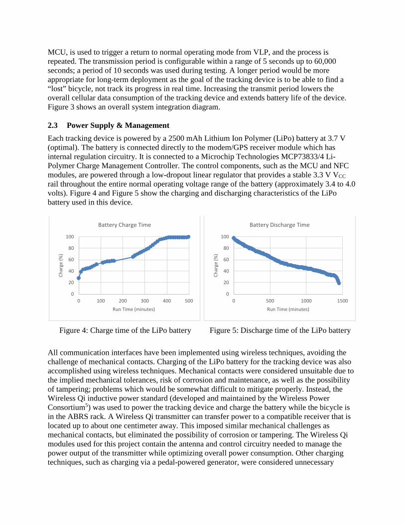
MCU, is used to trigger a return to normal operating mode from VLP, and the process is repeated. The transmission period is configurable within a range of 5 seconds up to 60,000 seconds; a period of 10 seconds was used during testing. A longer period would be more appropriate for long-term deployment as the goal of the tracking device is to be able to find a “lost” bicycle, not track its progress in real time. Increasing the transmit period lowers the overall cellular data consumption of the tracking device and extends battery life of the device. Figure 3 shows an overall system integration diagram. 2.3 Power Supply & Management Each tracking device is powered by a 2500 mAh Lithium Ion Polymer (LiPo) battery at 3.7 V (optimal). The battery is connected directly to the modem/GPS receiver module which has internal regulation circuitry. It is connected to a Microchip Technologies MCP73833/4 Li-Polymer Charge Management Controller. The control components, such as the MCU and NFC modules, are powered through a low-dropout linear regulator that provides a stable 3.3 V VCC rail throughout the entire normal operating voltage range of the battery (approximately 3.4 to 4.0 volts). Figure 4 and Figure 5 show the charging and discharging characteristics of the LiPo battery used in this device.
Figure 4: Charge time of the LiPo battery
Figure 5: Discharge time of the LiPo battery
All communication interfaces have been implemented using wireless techniques, avoiding the challenge of mechanical contacts. Charging of the LiPo battery for the tracking device was also accomplished using wireless techniques. Mechanical contacts were considered unsuitable due to the implied mechanical tolerances, risk of corrosion and maintenance, as well as the possibility of tampering; problems which would be somewhat difficult to mitigate properly. Instead, the Wireless Qi inductive power standard (developed and maintained by the Wireless Power Consortium5) was used to power the tracking device and charge the battery while the bicycle is in the ABRS rack. A Wireless Qi transmitter can transfer power to a compatible receiver that is located up to about one centimeter away. This imposed similar mechanical challenges as mechanical contacts, but eliminated the possibility of corrosion or tampering. The Wireless Qi modules used for this project contain the antenna and control circuitry needed to manage the power output of the transmitter while optimizing overall power consumption. Other charging techniques, such as charging via a pedal-powered generator, were considered unnecessary
0
20
40
60
80
100
0 100 200 300 400 500
Char
ge (%
)
Run Time (minutes)
Battery Charge Time
0
20
40
60
80
100
0 500 1000 1500
Char
ge (%
)
Run Time (minutes)
Battery Discharge Time

because the battery discharge time provided sufficient time for a typical rental as shown in Figure 5. 3 Device Implementation & Assembly 3.1 Main PCB The SIM808 GSM / GPS module, the KL17 MCU, charge controller, regulator, and other support components are mounted on a main Printed Circuit Board (PCB) to which other peripherals are attached. This 4-layer PCB is about 1.2 inches square, with ground planes on the outer layers, and most of the routing done in the internal layers. The assembled main PCB is shown in Figure 6 and Figure 7.
Figure 6: Front of tracking device PCB
Figure 7: Back of tracking device PCB
Figure 8: Tracking device components

Connected to the PCB are the NFC module, Qi Wireless Charger Receiver, GSM and GPS antennas, and a Lithium Ion Polymer battery. These components are housed in a 3D printed ABS plastic enclosure that is mounted on the front of a bicycle. These components, minus the enclosure, are shown in Figure 8. The complete GPS tracking device, with all components fitted into the ABS enclosure is shown in Figure 9. Figure 10 shows the ABS enclosure mounted to the front fork of a bicycle. The cost for the components of the tracking device assembly, not including the enclosure or mounting hardware, is approximately $85.00.
Figure 9: Components in ABRS enclosure
Figure 10: ABRS enclosure mounted on bicycle
3.2 Tracking Device User Interface The tracking device periodically transmits location information to a backend server where it is processed and stored in a database. This database stores a history of GPS locations for each tracking device in the system. The Google Maps API is used to display locations of each bicycle in the system to authenticated administrators. Figure 11 shows an example of the tracking interface, with three bicycles/bicycle tracking devices enabled.
Figure 11: Bicycle tracking interface, administrator view

4 Considerations for Future Improvement As previously mentioned, GSM support is nearing end-of-life for the AT&T network; other cellular networks are likely to follow in the near future. Meanwhile, the cost of 3G and LTE modems has been decreasing. Therefore, future revisions of the tracking device could be adapted to use a 3G or LTE modem without a significant cost increase. Battery lifetime is another factor that could be improved upon. With the 2500 mAh LiPo battery, the tracking device has about a 30-hour operational lifetime. By utilizing low power modes on both the NFC controller and especially the modem, this could be increased significantly. Finally, by using a backend server capable of processing UDP datagrams and improving the efficiency of the proprietary application protocol, the data consumption of each tracking device can be significantly decreased, resulting in significantly decreased operating costs and extending battery life. 5 Learning Outcomes All students that worked on the ABRS capstone project were assessed on a number of ABET learning outcomes. The team of students that designed the GPS-based tracking device consisted of two students, one electrical engineering student and one computer engineering student. Outcomes were assessed through a combination of faculty observation, submission of student work, and in-class demonstrations. The assessed ABET learning outcomes and how they apply to the tracking device portion of the ABRS project follows.
• (c) An ability to design a system, component, or process to meet desired needs within realistic constraints – The tracking device team was responsible for designing, testing, and building the device to track bicycles for the ABRS project. The design required that the team satisfy a number of constraints including cost, communication range, power consumption, and security. At $85 per unit, the tracking device satisfies a constraint that the unit cost less than $100. The device utilizes GPRS/GSM to ensure that it can communicate its position to a backend server from anywhere within the cellular network. To achieve a minimum of a 24-hour battery life, the device incorporates low power components and transmits location information every 10 seconds. The 10 second interval is sufficient for discovering lost bicycles but long enough to provide up to 30 hours of battery life. Finally, when returned to the ABRS rack, the device communicates securely with the rack to authenticate itself and provide status information. Secure communication is important to ensure that the device cannot be easily spoofed. A rubric for this learning outcome is shown in Table 1.
• (d) An ability to function on multidisciplinary teams – Two students worked on the GPS-based tracking device, one was an electrical engineering student and the other a computer engineering student. These two students worked closely with a small team of mechanical engineers to design a suitable weather-proof enclosure for the tracking device. The enclosure was designed to satisfy the narrow tolerances of the NFC and wireless charging interfaces, ensuring that the tracking device components aligned with their complementary components on the ABRS rack.

• (e) An ability to identify, formulate, and solve engineering problems – Students were provided minimal guidance as they identified and solved engineering problems related to the tracking device. As part of the process, the tracking device team evaluated a variety of technologies to satisfy each of their requirements. For example, 3G, LTE, and even WiFi technologies were considered for communication with the backend server. It was determined that the 3G and LTE options were too expensive to meet the cost requirements while WiFi did not offer the required range. Charging the device presented another challenge. Mechanical connections to the ABRS rack would require very tight tolerances to ensure the device charged while the bicycle was locked in a rack. The tracking device team determined that wireless charging could satisfy their power requirements and that the looser mechanical tolerances provided the mechanical engineering team more flexibility in the physical design of their locking mechanism.
• (g) An ability to communicate effectively – The tracking device integrates with many other components of the ABRS project. Specifically, the tracking device team communicated with a team of mechanical engineers to determine how and where the tracking devices should be mounted onto bicycles. Selecting an appropriate mounting location was crucial to ensuring that the device can charge and communicate wirelessly with the rack when a bicycle is locked. The tracking device team also worked closely with a team developing the distributed embedded system located in the ABRS rack. These two teams devised and documented a protocol that enables the tracking device to securely authenticate itself with the rack and to communicate status information. Finally, the tracking device team effectively communicated with a team developing a backend server for the ABRS project. Together, they designed and documented a communication protocol for transmitting GPS location information and device status to the backend server.
• (k) An ability to use the techniques, skills, and modern engineering tools necessary for engineering practice – Throughout the design and development process the GPS tracking device team made use of a variety of engineering tools and techniques. They utilized the Kinetis Software Development Kit (SDK) and hardware development kit to develop the initial software. Schematic capture and PCB layout tools were also incorporated. Testing and debugging of the custom PCB was done using standard laboratory equipment such as multi-meters and oscilloscopes.
Based on rubrics for each of the learning outcomes and instructors’ observations throughout the duration of the project, one of the two students exceeded expectations on all five of the student learning outcomes presented above. The second student met expectations on the five learning outcomes. 6 Conclusions The ABRS bicycle tracking device provides a low-cost solution to tracking and potentially recovering lost or stolen bicycles. By utilizing wireless communication and power transfer, potentially troublesome mechanical contacts are eliminated. Cellular data communication allows for a very wide operating range in various conditions with minimal maintenance requirements. A photo of the entire ABRS team is shown in Figure 12.

Table 1: Assessment rubric for learning outcome (c) Attribute Exceeds Expectations Meets Expectations Below Expectations
• Design and implement a wireless GPS tracking device to determine its location which is then transmitted to a backend server over a cellular network
• Economic and technical optimization in selecting parts
• Successfully defines a communication protocol for communication with backend
• Correctly identifies the hardware and software requirements to support Communication & Authentication features
• Successfully demonstrates System Control & Tracking features
• Successfully implements and demonstrates Power Supply & Management features
• The device cost is under budget ($100.00) considering economic and technical optimization
Minor errors in no more than two areas: • Communication
protocol • Communications &
Authentication • System Control &
Tracking • Power Supply &
Management • Economic and
technical optimization
Any major conceptual error, or minor errors in more than two areas: • Communication
protocol • Communications &
Authentication • System Control &
Tracking • Power Supply &
Management • Economic and
technical optimization
Figure 12: Group photo at unveiling event

References [1] Kiefer, Scott; Ericson, Tristan; Meah, Kala; Moscola, James, “Design, Build, and Installation of an Automated
Bike Rental System as a Part of Capstone Design,” ASEE 123rd Annual Conference & Exposition, New Orleans, LA, June 26-29, 2016.
[2] "SIM808", Simcomm2m.com, 2016. [Online]. Available: http://simcomm2m.com/En/module/detail.aspx?id=137
[3] Product short data sheet, Rev. 3.0. (2011, November 10). Near Field Communication Controller Application Note, [Online]. Available: http://www.nxp.com/documents/short_data_sheet/PN532_SDS.pdf
[4] KINETIS-SDK: Software Development Kit for Kinetis MCUs, [Online]. Available: http://www.nxp.com/products/software-and-tools/run-time-software/kinetis-software-and-tools/development-platforms-with-mbed/software-development-kit-for-kinetis-mcus:KINETIS-SDK
[5] "Wireless Power Consortium", wirelesspowerconsortium.com, 2016.


![Holux Wireless GPS Logger - [ ]](https://static.fdocuments.in/doc/165x107/61fb84c32e268c58cd5f1fcb/holux-wireless-gps-logger-.jpg)