QK-A026-plus Wireless AIS + GPS Receiver Manual
22
QK-A026-plus Manual V 1.0 1 of 22 2020 QK-A026-plus Wireless AIS + GPS Receiver Manual With SeaTalk 1 Converter NMEA 2000/ 0183/ WiFi/ USB output Multiplexing additional NMEA 0183 input Built-in NMEA 0183 to NMEA 2000 Converter Features • Two independent receivers monitoring AIS channels (161.975MHz & 162.025MHz) and decoding both channels simultaneously • Sensitivity up to -112 dBm@30% PER (where A026 is -105dBm) • Up to 50 nautical miles receiving range • SeaTalk 1 to NMEA 0183 protocol converter • NMEA 0183 message output through WiFi, USB and NMEA 0183 • Built-in GPS to provide positional data • Multiplexing NMEA input with AIS+GPS sentences, and outputs as a seamless stream of data • Convert the combined NMEA 0183 data into NMEA 2000 PGNs • Ad-hoc/station/standby operating modes on WiFi • The internal WiFi access point connects up to 4 devices simultaneously • Plug & Play connectivity with chart plotters and PCs • Compatible with Windows, Mac, Linux, Android and iOS (Initial configuration must be completed using Windows software.) • This device connects to NMEA 0183 and is compatible with RS422 output devices. NMEA 0183- RS232 devices can connect to our device by using the Protocol Bridge (QK-AS03)
Transcript of QK-A026-plus Wireless AIS + GPS Receiver Manual

QK-A026-plus Manual
V 1.0 1 of 22 2020
QK-A026-plus Wireless AIS + GPS Receiver Manual
With SeaTalk1 Converter
NMEA 2000/ 0183/ WiFi/ USB output
Multiplexing additional NMEA 0183 input
Built-in NMEA 0183 to NMEA 2000 Converter
Features
• Two independent receivers monitoring AIS channels (161.975MHz & 162.025MHz) and decoding
both channels simultaneously
• Sensitivity up to -112 dBm@30% PER (where A026 is -105dBm)
• Up to 50 nautical miles receiving range
• SeaTalk1 to NMEA 0183 protocol converter
• NMEA 0183 message output through WiFi, USB and NMEA 0183
• Built-in GPS to provide positional data
• Multiplexing NMEA input with AIS+GPS sentences, and outputs as a seamless stream of data
• Convert the combined NMEA 0183 data into NMEA 2000 PGNs
• Ad-hoc/station/standby operating modes on WiFi
• The internal WiFi access point connects up to 4 devices simultaneously
• Plug & Play connectivity with chart plotters and PCs
• Compatible with Windows, Mac, Linux, Android and iOS (Initial configuration must be completed
using Windows software.)
• This device connects to NMEA 0183 and is compatible with RS422 output devices. NMEA 0183-
RS232 devices can connect to our device by using the Protocol Bridge (QK-AS03)
QK-A026-plus Manual
V 1.0 2 of 22 2020
Contents
1. Introduction ...................................................................................................................................... 3 2. Mounting .......................................................................................................................................... 3 3. Connections ..................................................................................................................................... 4
3.1. Status LEDs ......................................................................................................................... 6 3.2. Power ................................................................................................................................... 7 3.3. VHF/AIS antenna ................................................................................................................. 7 3.4. GPS antenna ....................................................................................................................... 7 3.5. NMEA input and output connection ..................................................................................... 8
NMEA 0183 default baud rates ............................................................................... 8 NMEA 0183 RS422 / RS232 ................................................................................... 8
3.6. SeaTalk1 Input ..................................................................................................................... 8 3.7. NMEA 2000 Port .................................................................................................................. 9 3.8. Conversion Lists .................................................................................................................. 9
NMEA 0183 to NMEA 2000 conversions .............................................................. 10 NMEA 2000 to NMEA 0183 conversions .............................................................. 10
3.9. WiFi connection ................................................................................................................. 11 WiFi Ad-hoc mode connection ............................................................................... 12
3.10. USB connection ............................................................................................................. 12 Will you need a driver to connect via USB? .......................................................... 12 Checking the USB connection (Windows) ............................................................. 13
4. Configuration (via USB) ................................................................................................................. 14 4.1. Configuring Baud Rates .................................................................................................... 15 4.2. WiFi - Station mode ........................................................................................................... 16 4.3. WiFi – Standby/Disable ..................................................................................................... 17 4.4. Filtering .............................................................................................................................. 17
Configuring filters ................................................................................................... 17 Routing data away from chosen outputs ............................................................... 17
4.5. USB - Monitoring NMEA Messages .................................................................................. 18 4.6. NMEA 2000 output format ................................................................................................. 18
5. Upgrading firmware ........................................................................................................................ 18 6. Chart software ................................................................................................................................ 18
6.1. Chart Software USB setup (OpenCPN example) .............................................................. 19 6.2. Chart Software WiFi Network Setup (OpenCPN example) ............................................... 19
7. Specification ................................................................................................................................... 21 8. Limited Warranty and Notices ........................................................................................................ 21 9. Disclaimer ...................................................................................................................................... 21 10. Document History ................................................................................................................... 22 11. Glossary ................................................................................................................................. 22 12. For more info… ...................................................................................................................... 22

QK-A026-plus Manual
V 1.0 3 of 22 2020
1. Introduction
The A026+ is a powerful and flexible dual channel AIS receiver with multiple integrated functions. It was designed to be a hub for on board navigation which is aimed at the commercial, sport, leisure, fishing boat and vessel monitoring markets.
The A026+ is equipped with a variety of output interfaces including NMEA 0183, USB, WiFi and NMEA 2000. Whether you are using a tablet, iPhone or an onboard computer you can easily setup your navigation system with most onboard devices via WiFi or USB.
The A026+ comes with a standard RS422 NMEA 0183 input. NMEA sentences from other on-board devices, like wind sensors, depth transductors, autopilots, radars, can all be multiplexed by the A026+ and then combined with internal AIS and GPS data.
The internal SeaTalk converter allows the A026+ to listen on the SeaTalk bus and convert SeaTalk data to NMEA messages. These messages then can be combined with other input NMEA data flows.
The A026+ model includes an integrated GPS module, which provides GPS data to all outputs when it is connected to a GPS antenna (TNC connection type).
The A026 built-in NMEA 2000 converter provides a NMEA 2000 network connection. The combined data can be converted to NMEA 2000 PGNs and visa-versa to USB and WiFi port. With A026+, WiFi data, USB data, NMEA 0183 input and SeaTalk1 input data can be available on new NMEA 2000 capable instruments, such as NMEA 2000 chart plotters. The WiFi and USB ports are capable of outputting the converted NMEA 2000 data while allowing users to view the raw or converted data transmitted on NMEA 2000 backbone.
When connected to an on-board PC running compatible software, or a chart plotter, the AIS data transmitted from ships within range will be displayed on the screen enabling the skipper or navigator to visualize the traffic within VHF range. Using your A026+ can enhance safety at sea by providing proximity, size and directional information from other vessels, improve safety and efficiency in navigation and help protect the marine environment.
Figure 1: A026+ function diagram
2. Mounting
Although the A026+ comes with an extruded aluminium enclosure to shield it from external RF interference, it should not be fitted close to generators or compressors (e.g. refrigerators) as they can generate substantial RF noise. It is designed to be installed in a protected indoor environment. Generally, a suitable placement of the A026+ is together with other types of navigation equipment and the PC or chart plotter that will be used to display the output data. The A026+ is designed to be securely mounted to a suitable bulkhead or shelf in an indoor environment and needs to be placed where it is well protected from humidity and water. Make sure to ensure there is enough space around the multiplexer to connect the wirings.

QK-A026-plus Manual
V 1.0 4 of 22 2020
Figure 2: Dimensions
3. Connections
Figure 3 Typical system connection

QK-A026-plus Manual
V 1.0 5 of 22 2020
The A26+ NMEA 2000 AIS+GPS receiver has the following options for connection to inputs, outputs and host devices.
• AIS antenna connector. A SO239 VHF connector for external AIS antenna. Connect externalAIS antenna. An active VHF antenna splitter is required if one VHF antenna is shared by A026+and VHF voice radio.
• GPS connector. A TNC female bulkhead connector is for external GPS antenna. An integratedGPS module supplies positional data provided a GPS antenna is connected.
• WiFi. Connectivity in both Ad-hoc and Station Modes on 802.11 b/g/n provides WiFi output of allmessages. WiFi can also be disabled by setup into standby mode.
• NMEA 0183 input/output connectors. A026+ can be connected to other AIS compatible
equipment, like wind/depth or heading sensors, via the NMEA inputs. The NMEA 0183 messages
from these devices can be multiplexed with AIS+GPS messages and then sent out through the
NMEA 0183 output, WiFi, USB and NMEA 2000 backbone to a chart plotter or other on-board
device.
• USB connector. The A026+ is supplied with a type B USB connector and USB cable. The USB
cable can be linked directly to a USB port on the PC. The USB connector provides data input and
output as standard (multiplexed information from all input instruments will be sent to this
connection). The USB port is also used to configure the A026+ and to update its firmware.
• NMEA 2000. The A026+ is pre-fitted with a five-core screened cable for the NMEA 2000connection, fitted with a male micro-fit connector. Simply connect the cable to the networkbackbone using a T-piece connector. An NMEA 2000 backbone always requires two terminationresistors, one at each end.
Figure 4: Pin NMEA 2000 male micro-fit connection
Figure 5 A026+ bottom side view
Figure 6 A026+ top side view
QK-A026-plus Manual
V 1.0 6 of 22 2020
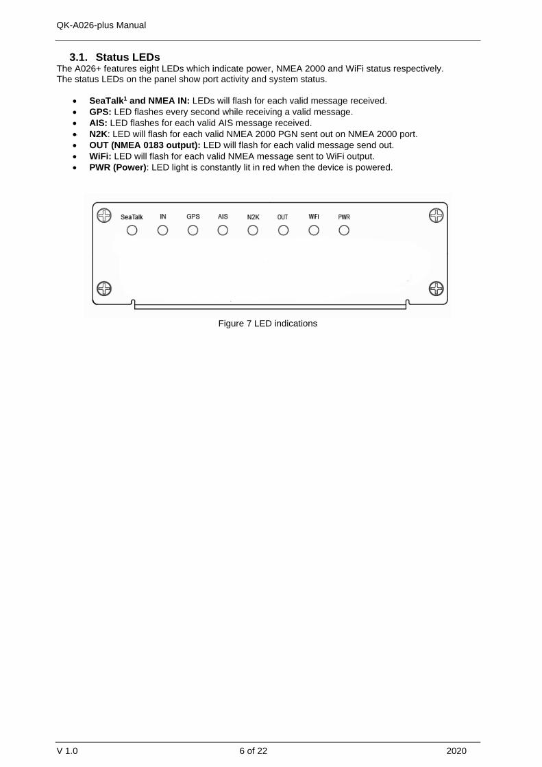
3.1. Status LEDs The A026+ features eight LEDs which indicate power, NMEA 2000 and WiFi status respectively. The status LEDs on the panel show port activity and system status.
• SeaTalk1 and NMEA IN: LEDs will flash for each valid message received.
• GPS: LED flashes every second while receiving a valid message.
• AIS: LED flashes for each valid AIS message received.
• N2K: LED will flash for each valid NMEA 2000 PGN sent out on NMEA 2000 port.
• OUT (NMEA 0183 output): LED will flash for each valid message send out.
• WiFi: LED will flash for each valid NMEA message sent to WiFi output.
• PWR (Power): LED light is constantly lit in red when the device is powered.
Figure 7 LED indications

QK-A026-plus Manual
V 1.0 7 of 22 2020
3.2. Power The A026+ operates on 12V DC. Power and GND are clearly indicated. Ensure these are connected correctly. The A026+ benefits from reverse polarity protection to protect the device in case of faulty installation. Ensure you use a reliable 12V power supply. A poorly designed power supply or battery, if connected directly with the engine or other noisy devices could result in significantly degraded receiver performance.
3.3. VHF/AIS antenna The A026+ is not supplied with a VHF antenna, as the antenna and cable requirements differ from vessel to vessel. A suitable VHF antenna must be connected before the receiver will operate fully.
AIS communication systems use frequencies in the maritime VHF band, which is considered to be ‘line of sight’ radio. This means that if an AIS receiver’s antenna cannot ‘see’ the antennas of other vessels, the AIS signals from vessels will not reach that receiver. In practice, this is not a strict requirement, a few buildings and trees between may be fine. Large obstacles such as hills and mountains, on the other hand, will significantly degrade the AIS signal.
To have the best possible receiving range, the AIS antenna should be placed as high as possible with a relatively clear view of the horizon. Large obstructions might shade the AIS radio communication from certain directions, giving uneven coverage.
VHF antennas can be used for AIS messages or radio communications. One antenna cannot be connected to both AIS and VHF radio equipment unless an active VHF/AIS splitter is used. There are important considerations when deciding whether to use two separate antennas or a combined antenna:
• 2 VHF antennas: The best reception is achieved by using two separate antennas, one for AISand one for VHF radio. The antennas must be separated as much space as possible (ideally atleast 3.0 meters). A good distance between the AIS/VHF antenna and the radio communicationVHF antenna is required to avoid interference.
• 1 shared VHF antenna: If using only one antenna, e.g. Using an existing VHF radio antenna toreceive AIS signals, proper separation equipment (an active VHF Splitter) must be installedbetween the antenna and the connected equipment.
Figure 8: AIS (SO239), GPS (TNC), and WiFi(SMA) antenna connections
3.4. GPS antenna A TNC female bulkhead 50 Ohm connector is for an external GPS antenna (not included).
For best results, the GPS antenna should be located in ‘line of sight’ of the sky. Once connected to a GPS antenna, the integrated GPS module supplies positional data to the NMEA 0183 output, WiFi and USB. GPS output can be disabled when an external GPS signal is used.
QK-A026-plus Manual
V 1.0 8 of 22 2020
3.5. NMEA input and output connection NMEA 0183 input/output ports allow for connection to NMEA 0183 instruments and a chart plotter. The built-in multiplexer combines the input NMEA 0183 data (e.g., wind/depth/radar) with the AIS and GPS data and sends the combined data stream to all outputs, including the NMEA 0183 output port.
NMEA 0183 default baud rates ‘Baud rates’ refer to the data transfer speed. When connecting two NMEA 0183 devices, both devices’ baud rates, must be set to the same speed.
• The A026+ input port’s default baud rate is 4800bps as it is usually connected to low speedNMEA format data instruments, like heading, sounder, or wind/depth sensors.
• The A026+ output port’s default baud rate is 38400bps. The connected chart plotter should beconfigured at this rate to receive the proper data as AIS data requires this higher speed.
These are the default baud rate settings and are most likely to be the baud rates required, however, both baud rates are configurable if needed. Baud rates can be adjusted using the Configuration software. (See Configuration section)
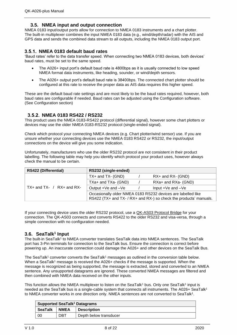
NMEA 0183 RS422 / RS232 This product uses the NMEA 0183-RS422 protocol (differential signal), however some chart plotters or devices may use the older NMEA 0183-RS232 protocol (single-ended signal).
Check which protocol your connecting NMEA devices (e.g. Chart plotter/wind sensor) use. If you are unsure whether your connecting devices use the NMEA 0183 RS422 or RS232, the input/output connections on the device will give you some indication.
Unfortunately, manufacturers who use the older RS232 protocol are not consistent in their product labelling. The following table may help you identify which protocol your product uses, however always check the manual to be certain.
If your connecting device uses the older RS232 protocol, use a QK-AS03 Protocol Bridge for your connection. The QK-AS03 connects and converts RS422 to the older RS232 and visa-versa, through a simple connection with no configuration needed.
3.6. SeaTalk1 Input The built-in SeaTalk1 to NMEA converter translates SeaTalk data into NMEA sentences. The SeaTalk port has 3-Pin terminals for connection to the SeaTalk bus. Ensure the connection is correct before powering up. An inaccurate connection could damage the A026+ and other devices on the SeaTalk Bus.
The SeaTalk1 converter converts the SeaTalk1 messages as outlined in the conversion table below. When a SeaTalk1 message is received the A026+ checks if the message is supported. When the message is recognized as being supported, the message is extracted, stored and converted to an NMEA sentence. Any unsupported datagrams are ignored. These converted NMEA messages are filtered and then combined with NMEA data received on the other inputs.
This function allows the NMEA multiplexer to listen on the SeaTalk1 bus. Only one SeaTalk1 input is needed as the SeaTalk bus is a single-cable system that connects all instruments. The A026+ SeaTalk1 to NMEA converter works in one direction only. NMEA sentences are not converted to SeaTalk1.
Supported SeaTalk1 Datagrams
SeaTalk NMEA Description
00 DBT Depth below transducer
RS422 (Differential) RS232 (single-ended)
TX+ and TX- / RX+ and RX-
TX+ and TX- (GND) / RX+ and RX- (GND)
TXa+ and TXa- (GND) / RXa+ and RXa- (GND)
Output +Ve and –Ve / Input +Ve and –Ve
Occasionally older NMEA 0183 RS232 devices are labelled like RS422 (TX+ and TX- / RX+ and RX-) so check the products’ manuals.

QK-A026-plus Manual
V 1.0 9 of 22 2020
10 MWV Wind angle, (10 and 11 combined)
11 MWV Wind speed, (10 and 11 combined)
20 VHW Speed through water, includes heading when present
21 VLW Trip mileage (21 and 22 combined)
22 VLW Total mileage (21 and 22 combined)
23 MTW Water temperature
25 VLW Total and Trip mileage
26 VHW Speed through water, includes heading when present
27 MTW Water temperature
50 --- GPS latitude, value stored
51 --- GPS longitude, value stored
52 --- GPS speed over ground, value stored
53 RMC Course over ground. RMC sentence is generated from stored values from other GPS related datagrams.
54 --- GPS time, value stored
56 --- GPS date, value stored
58 --- GPS lat/long, values stored
89 HDG Magnetic heading, including variation (99)
99 --- Magnetic variation, value stored
AS the table shows, not all datagrams result in an NMEA 0183 sentence. Some datagrams are only used to retrieve data, which is combined with other datagrams to create one NMEA 0183 sentence.
3.7. NMEA 2000 Port The A026+ converter provides a NMEA 2000 network connection. The A026+ combines all the NMEA 0183 data inputs and then converts them to be NMEA 2000 PGNs. With the A026+ all WiFi data, USB data and NMEA 0183 input and SeaTalk1 input data can be available on more modern NMEA 2000 capable instruments, such as NMEA 2000 chart plotters.
NMEA 2000 networks must at least consist of, a powered backbone with two terminators (termination resistors), to which the multiplexer and any other NMEA 2000 devices must be connected.
Each NMEA 2000 device connects to the backbone. It is not possible to simply connect two NMEA 2000 devices directly together. The A026+ is supplied with a spurred five-core screened cable for the NMEA 2000 connection, fitted with a male micro-fit connector. Simply connect the cable to the network backbone.
3.8. Conversion Lists The conversion tables on the following pages list the supported NMEA 2000 PGN’s (parameter group numbers) and NMEA 0183 sentences. It is important to check the tables to confirm that the A026+ will convert the sentences/PGNs required.
Through USB and WiFi, the A026+ will output in NMEA 0183 format, including all NMEA 0183 messages received and NMEA 0183 messages converted from the NMEA 2000 network.
WiFi/USB inputs are NMEA 0183 messages and are converted to NMEA 2000 for the NMEA 2000 bus.
The following is a typical PCDIN message format outputted through WiFi and USB. The chart software will convert this into more meaningful information.
---Received message: $PCDIN, 01F119, 00000000, 16,0064050800FFFF0C*5B---
Header PGN Time Stamp Source ID Data Termination Check Sum
$PCDIN 01F119 00000000 16 0064050800FFFF0C * 5B
QK-A026-plus Manual
V 1.0 10 of 22 2020
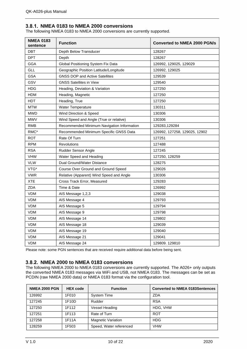
NMEA 0183 to NMEA 2000 conversions The following NMEA 0183 to NMEA 2000 conversions are currently supported.
NMEA 0183 sentence
Function Converted to NMEA 2000 PGN/s
DBT Depth Below Transducer 128267
DPT Depth 128267
GGA Global Positioning System Fix Data 126992, 129025, 129029
GLL Geographic Position Latitude/Longitude 126992, 129025
GSA GNSS DOP and Active Satellites 129539
GSV GNSS Satellites in View 129540
HDG Heading, Deviation & Variation 127250
HDM Heading, Magnetic 127250
HDT Heading, True 127250
MTW Water Temperature 130311
MWD Wind Direction & Speed 130306
MWV Wind Speed and Angle (True or relative) 130306
RMB Recommended Minimum Navigation Information 129283,129284
RMC* Recommended Minimum Specific GNSS Data 126992, 127258, 129025, 12902
ROT Rate Of Turn 127251
RPM Revolutions 127488
RSA Rudder Sensor Angle 127245
VHW Water Speed and Heading 127250, 128259
VLW Dual Ground/Water Distance 128275
VTG* Course Over Ground and Ground Speed 129026
VWR Relative (Apparent) Wind Speed and Angle 130306
XTE Cross Track Error, Measured 129283
ZDA Time & Date 126992
VDM AIS Message 1,2,3 129038
VDM AIS Message 4 129793
VDM AIS Message 5 129794
VDM AIS Message 9 129798
VDM AIS Message 14 129802
VDM AIS Message 18 129039
VDM AIS Message 19 129040
VDM AIS Message 21 129041
VDM AIS Message 24 129809. 129810
Please note: some PGN sentences that are received require additional data before being sent.
NMEA 2000 to NMEA 0183 conversions The following NMEA 2000 to NMEA 0183 conversions are currently supported. The A026+ only outputs the converted NMEA 0183 messages via WiFi and USB, not NMEA 0183. The messages can be set as PCDIN (raw NMEA 2000 data) or NMEA 0183 format via the configuration tool.
NMEA 2000 PGN HEX code Function Converted to NMEA 0183Sentences
126992 1F010 System Time ZDA
127245 1F10D Rudder RSA
127250 1F112 Vessel Heading HDG, VHW
127251 1F113 Rate of Turn ROT
127258 1F11A Magnetic Variation HDG
128259 1F503 Speed, Water referenced VHW

QK-A026-plus Manual
V 1.0 11 of 22 2020
128267 1F50B Water Depth DBT, DPT
128275 1F513 Distance Log VLW
129025 1F801 Position, Rapid Update GLL
129026 1F802 COG & SOG, Rapid Update VTG
129029 1F805 GNSS Position Data GGA, GLL, GSA, RMC, ZDA
129033 1F809 Time & Date ZDA
129044 1F814 Datum DTM
129283 1F903 Cross Track Error APB, RMB, XTE
129284 1F904 Navigation Data RMB
129291 1F90B Set & Drift, Rapid Update VDR
129539 1FA03 GNSS DOPs GSA
129540 1FA04 GNSS Sats in View GSV
130306 1FD02 Wind Data MWV
130310 1FD06 Environmental Parameters MDA, MTW
130311 1FD07 Environmental Parameters MDA
130312 1FD08 Temperature MDA, MTW
129038 1F80E AIS Message 1,2,3 VDM
129793 1FB01 AIS Message 4 VDM
129794 1FB02 AIS Message 5 VDM
129798 1FB06 AIS Message 9 VDM
129039 1F80F AIS Message 18 VDM
129040 1F810 AIS Message 19 VDM
129809 1FB11 AIS Message 24 (Part A) VDM
129810 1FB12 AIS Message 24 (Part B) VDM
Please note: some PGN sentences that are received require additional data before being sent.
3.9. WiFi connection The A026+ allows users to view their data through WiFi on a PC, tablet, smartphone or other WiFi enabled device. Users can access marine network data including vessel course, speed, position, wind speed, direction, water depth, AIS etc. These can be viewed in the chart software.
The IEEE 802.11b/g/n wireless standard has two basic modes of operation: Ad-hoc mode (peer to peer) and Station mode (also called infrastructure mode).
The A026+ supports 3 WiFi modes: Ad-hoc, Station and Standby(disabled).
Figure 9 WiFi supports mode
• In Ad-hoc mode, wireless devices connect directly (peer to peer) without a router or access point.For example, your smartphone can connect directly to the A026+ to receive marine data.

QK-A026-plus Manual
V 1.0 12 of 22 2020
• In Station mode, wireless devices communicate through an access point (AP) such as a router thatserves as a bridge to other networks (such as the Internet or LAN). This allows your router to handlethe data and traffic from your device. This data can then be picked up through your router anywhereon your local area network. Similar to plugging the device directly into the router, but using wirelesstechnology. This way, the mobile devices receive both your marine data and other AP connectionssuch as Internet.
• In Standby mode, WiFi can be disabled. This reduces power consumption and may be requiredwhen connecting 2 WiFi transmitting devices.
The A026+ is set to Ad-hoc mode as a default setting, but can be easily setup to Station mode through the configuration tool. (See Configuration section)
WiFi Ad-hoc mode connection
From a Phone, Tablet or PC:
Once the A026+ has powered up, scan for a WiFi network with an SSID of ‘QK-A026xxxx’ or similar.
Connect to ‘QK-A026xxxx’ with the default password: ‘88888888’.
Note: The SSID and password can be changed if desired. The password must be 8 to 12 characters long. If changing the SSID and password, A026+ should be reset to activate the settings. (The IP address, Gateway, Net Mask and Port can be left blank if no fixed IP address is needed.)
In your chart software (or chart plotter): Set the protocol to ‘TCP’, IP address to ‘192.168.1.100’ and the port number to ‘2000’.
Note: In Ad-hoc mode, the IP address should not be changed.
With the above settings, a wireless connection is established and the user will receive the data through the chart software. (More information in the Chart software section)
The wireless connection and data flow can be checked with TCP/IP port monitoring software.
To Configure Station mode see the Configuration section.
3.10. USB connection The A026+ is supplied with a type-B USB connector and USB cable. This USB connector can be linked directly to a USB port on a PC. The USB connector provides data input and output as standard (multiplexed information from all input instruments will be sent to this connection). The USB port is also used to configure the A026+ and to update its firmware.
Will you need a driver to connect via USB? To enable the USB data connection of A026+ to other devices, related hardware drivers may be needed depending on your system requirements.
Mac: No driver required. For Mac OS X, the A026+ will be recognized and shown as a USB modem. The ID can be checked with the following steps:
1. Plug the A026+ into a USB port and launch Terminal.app.
A026+ SSID Similar to ‘QK-A026xxxx’
WiFi password 88888888
Protocol TCP
IP address 192.168.1.100
Data Port 2000
Figure 10: TCP/IP Net Assistant example

QK-A026-plus Manual
V 1.0 13 of 22 2020
2. Type: Is /dev/*sub*
3. The Mac system will return a list of USB devices. A026+ will display as - “/dev/tty.usbmodemXYZ”where XYZ is a number. Nothing further needs to be done if it is listed.
Windows 7,8,10: The drivers usually install automatically if your device is running an original Windows 10 version. A new COM port will automatically show up in the device manager once powered and connected via USB.
The A026+ registers itself to the computer as a virtual serial com port.
Linux: No driver required. When plugged into the computer, the A026+ will show up as a USB CDC device on /dev/ttyACM0.
Checking the USB connection (Windows)
After the driver is installed (if needed), run the Device Manager and check the COM (port) number. The port number is the number assigned to an input device. These can be generated randomly by your computer. Your chart software may require your COM port number in order to access the data.
The port number for the A026+ can be found in Windows ‘Control Panel>System>Device Manager’ under ‘Ports (COM & LPT)’. Find something similar to ‘STMicroelectronics Virtual Com Port’ in the list for the USB port. If the port number needs to be changed for some reason, double click the A026+ and select the ‘Port Settings’ tab. Click the ‘Advanced’ button and change the port number to the one required.
Figure 11: View of COM port in Device Manager
The USB connection status can always be checked with a terminal monitor application like Putty or
HyperTerminal. Ensure that the COM Port is set at 38400bps, 8, N and 1 as shown below using
HyperTerminal on Windows as an example.
To use a terminal monitor application, first connect A026+ to the computer, follow the instructions to
install the driver if required. After the driver is installed, run the Device Manager and check the COM
(Port) number.
QK-A026-plus Manual
V 1.0 14 of 22 2020
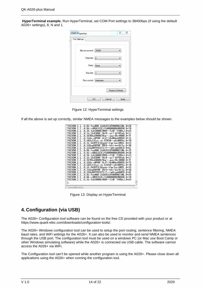
HyperTerminal example. Run HyperTerminal, set COM Port settings to 38400bps (if using the default A026+ settings), 8, N and 1.
Figure 12: HyperTerminal settings
If all the above is set up correctly, similar NMEA messages to the examples below should be shown.
Figure 13: Display on HyperTerminal
4. Configuration (via USB)
The A026+ Configuration tool software can be found on the free CD provided with your product or at https://www.quark-elec.com/downloads/configuration-tools/.
The A026+ Windows configuration tool can be used to setup the port routing, sentence filtering, NMEA baud rates, and WiFi settings for the A026+. It can also be used to monitor and send NMEA sentences through the USB port. The configuration tool must be used on a windows PC (or Mac use Boot Camp or other Windows simulating software) while the A026+ is connected via USB cable. The software cannot access the A026+ via WiFi.
The Configuration tool can’t be opened while another program is using the A026+. Please close down all applications using the A026+ when running the configuration tool.

QK-A026-plus Manual
V 1.0 15 of 22 2020
Once open, click ‘Connect’. When the A026+ is connected to a computer (Windows system) and powered up the application will indicate if it successfully connected at the bottom center of the app and the software version will be shown at the bottom right. Press ‘Config’ once you have set the Baud rates for the inputs to save them to the A026+. Then press the ‘Disconnect’ button to safely remove the device from the PC. Re-start the A026+ to activate the new settings on your device.
The free Configuration software comes with the CD provided.
The configuration tool must be used when plugged into a windows PC via USB cable. The tool cannot be accessed via WiFi.
The configuration tool must not be opened while other programs are using the A026+. Close down all applications using the A026+ before using the configuration tool.
4.1. Configuring Baud Rates
The NMEA 0183 input and output baud rates can be setup from dropdown menu. The A026+ can work with standard NMEA 0183 devices at 4800bps as default, the high-speed NMEA 0183 devices (38400bps) and 9600bps can also be configured if necessary, via the configuration tool.

QK-A026-plus Manual
V 1.0 16 of 22 2020
Figure 14 Setup the baud rate
4.2. WiFi - Station mode
WiFi is set to Ad-hoc mode by default. Station mode however, allows your router/access point to handle the data from your device. This data can then be picked up through your router anywhere on your local area network (Similar to plugging the device directly into the router, but using wireless technology). This allows your mobile device to still receive Internet while viewing your marine data.
To begin setting up station mode the A026+ should be connected via USB to a computer running Windows (Mac users can use BootCamp).
1. Connect the A026+ to computer via Micro USB B connection.2. Run the Configuration software (having closed any other programs that would access the A026+)3. Click ‘Connect’ and check connection to the A026+ at the bottom of Configuration tool.
4. Change working mode to ‘Station mode’5. Enter your router’s SSID.6. Enter the password for your network.7. Enter the IP address assigned to the A026+, this normally starts
with 192.168. The third group of digits depends on your router’sconfiguration (commonly 1 or 0). The fourth group must be aunique number between 0 and 255). This number must not beused by any other equipment connected to your router.
8. Enter your router’s IP address in the Gateway section. This canusually be found under the router. Leave the other settings asthey are.
9. Click ‘Config’ in the bottom right-hand corner and wait 60seconds. After 60 seconds Click ‘Disconnect’.
10. Repower the A026+ and it will now attempt to connect to therouter.
In your chart software, set the protocol as ‘TCP’, insert the IP address you assigned the A026+ and enter the Port number as ‘2000’.
You should now see your marine data in your chart software. If not, check your router’s IP address list and confirm the IP address that your router has assigned the A026+. Occasionally, a router assigns a different IP address to a device than the one you chose to assign it during Configuration. If this is the case, copy the IP address from the router into your chart software. If the IP address in the router’s IP address list matched the one inputted into the chart software, everything will work in station mode.
If you are not able to view your data in station mode, the likely cause is either the data has been input incorrectly, or the IP address is different in your chart software to that of your router.
QK-A026-plus Manual
V 1.0 17 of 22 2020
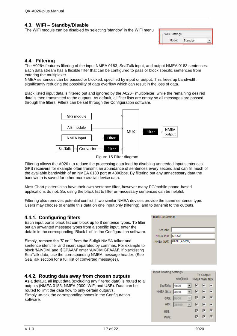
4.3. WiFi – Standby/Disable The WiFi module can be disabled by selecting ‘standby’ in the WiFi menu
4.4. Filtering The A026+ features filtering of the input NMEA 0183, SeaTalk input, and output NMEA 0183 sentences. Each data stream has a flexible filter that can be configured to pass or block specific sentences from entering the multiplexer. NMEA sentences can be passed or blocked, specified by input or output. This frees up bandwidth, significantly reducing the possibility of data overflow which can result in the loss of data.
Black listed input data is filtered out and ignored by the A026+ multiplexer, while the remaining desired data is then transmitted to the outputs. As default, all filter lists are empty so all messages are passed through the filters. Filters can be set through the Configuration software.
Figure 15 Filter diagram
Filtering allows the A026+ to reduce the processing data load by disabling unneeded input sentences. GPS receivers for example often transmit an abundance of sentences every second and can fill much of the available bandwidth of an NMEA 0183 port at 4800bps. By filtering out any unnecessary data the bandwidth is saved for other more crucial device data.
Most Chart plotters also have their own sentence filter, however many PC/mobile phone-based applications do not. So, using the black list to filter un-necessary sentences can be helpful.
Filtering also removes potential conflict if two similar NMEA devices provide the same sentence type. Users may choose to enable this data on one input only (filtering), and to transmit to the outputs.
Configuring filters Each input port’s black list can block up to 8 sentence types. To filter out an unwanted message types from a specific input, enter the details in the corresponding ‘Black List’ in the Configuration software.
Simply, remove the ‘$’ or ‘!’ from the 5-digit NMEA talker and sentence identifier and insert separated by commas. For example to block ‘!AIVDM’ and ‘$GPAAM’ enter ‘AIVDM,GPAAM’. If blacklisting SeaTalk data, use the corresponding NMEA message header. (See SeaTalk section for a full list of converted messages).
Routing data away from chosen outputs As a default, all input data (excluding any filtered data) is routed to all outputs (NMEA 0183, NMEA 2000, WiFi and USB). Data can be routed to limit the data flow to only certain output/s. Simply un-tick the corresponding boxes in the Configuration software.

QK-A026-plus Manual
V 1.0 18 of 22 2020
4.5. USB - Monitoring NMEA Messages Connect A026+ and then click ‘Open port’, all the sentences will be displayed in the application.
Figure 16: Monitor via USB
4.6. NMEA 2000 output format NMEA 2000 bus data can be sent out via WiFi and USB. The operator can setup the output format
through the configuration tool. It can be PCDIN (Raw NMEA 2000 data in NMEA 0183 format), NMEA
0183(converted PGNs) or standby mode (disable the output from NMEA 2000 bus).
Once settings are complete the user must click ‘Config’ and then click ‘Disconnect’. Please restart the unit by un plugging the unit from Power. The unit is now ready for use.
5. Upgrading firmware
The current firmware version can be verified through the configuration tool (When connected, the firmware version will show in the bottom of the Configuration software window).
To upgrade the firmware, 1. Power up your A026+ and then connect it to a Windows computer via USB.2. Run the Configuration software.3. Ensure the configuration tool is connected to the A026+, and then press Ctrl+F7.4. A new Window will pop up with a drive named ‘STM32’ or similar. Copy the firmware into this drive
and wait around 10 seconds to make sure the full file has been copied.5. Close the window and the Configuration software.6. Re-power the A026+, and the new firmware will be active.
6. Chart software
There is a wide range of chart software available, for example OpenCPN, Navionics.
• https://opencpn.org/OpenCPN (Open Chart Plotter Navigator) is a free software project to createconcise chart plotter and navigation software, for use underway or as a planning tool. OpenCPNis developed by a team of active sailors using real world conditions for program testing andrefinement.
• https://www.navionics.com/gbr/apps/navionics-boating

QK-A026-plus Manual
V 1.0 19 of 22 2020
We will use OpenCPN for our example, other software will require a similar setup.
The following is a sample setting for the OpenCPN plotter. COM2 was set as the A026+ input and in this case.
6.1. Chart Software USB setup (OpenCPN example)
When you open the software, you will be greeted with a page similar to the one below. (This is the main view of OpenCPN software.) You now need to add data to OpenCPN via your A026+ instruments.
Figure 17: OpenCPN main screen
1. Click on the ‘Options’ tab at the top.
2. Select the ‘Connections’ from the menu bar.
3. Click on ‘Add Connection’ button highlighted in the picture below.
4. Select ‘Serial’
5. Select the COM number assigned to A026+ (See connecting via USB to find the COM Port indevice manager).
6. Adjust the Baud rate accordingly (38400 covers AIS).
Click ‘Apply’ and then ‘OK’
Figure 18: Serial port setting in open CPN (example)
6.2. Chart Software WiFi Network Setup (OpenCPN example) For WiFi connection, ‘Network’ rather than ‘Serial’ needs to be selected in ‘Connections->Properties’ and the following settings need to be input.
1. Go to the ‘Options’ tab as above to set up a wireless network connection.
2. Select ‘Connections’ tab at the top of the options menu.
3. Click the ‘Add connection’ button.
4. Select ‘Network’
5. Input the Protocol: TCP
AIS input is in COM2

QK-A026-plus Manual
V 1.0 20 of 22 2020
6. Insert IP address. In Ad-hoc mode (direct WiFi connect) this is 192.168.1.100. (In Station modethis will be a different IP address, see WiFi Station Mode section)
7. Input the ‘DataPort’: 2000
8. Click ‘Apply’ and then ‘OK’
Figure 19: WiFi setting in OpenCPN (example)

QK-A026-plus Manual
V 1.0 21 of 22 2020
7. Specification
Item Specification
Frequency bands 161.975MHz &162.025MHz
Operating temperature -5°C to +80°C
Storage temperature -25°C to +85°C
DC supply 12.0V(+/- 10%)
Maximum supply current 255mA
AIS receive sensitivity -112dBm@30%PER (where A026 is -105dBm)
GPS receiver sensitivity -162dBm
NMEA data format ITU/ NMEA 0183 format
NMEA input data rate 4800bps
NMEA output data rate 38400bps
WiFi mode Ad-hoc and Station modes on 802.11 b/g/n
Security WPA/WPA2
Network Protocols TCP
8. Limited Warranty and Notices
Quark-elec warrants this product to be free from defects in materials and manufacture for two years from the date of purchase. Quark-elec will, at its sole discretion, repair or replace any components that fail in normal use. Such repairs or replacement will be made at no charge to the customer for parts and labour. The customer is, however, responsible for any transportation costs incurred in returning the unit to Quark-Elec. This warranty does not cover failures due to abuse, misuse, accident or unauthorized alteration or repairs. A returns number must be given before any unit is sent back for repair.
The above does not affect the statutory rights of the consumer.
9. Disclaimer
This product is designed to aid navigation and should be used to augment normal navigational procedures and practices. It is the user’s responsibility to use this product prudently. Neither Quark-elec, nor their distributors or dealers accept responsibility or liability either to the products user or their estate for any accident, loss, injury or damage whatsoever arising out of the use or of liability to use this product.
Quark- products may be upgraded from time to time and future versions may therefore not correspond exactly with this manual. The manufacturer of this product disclaims any liability for consequences arising from omissions or inaccuracies in this manual and any other documentation provided with this product.

QK-A026-plus Manual
V 1.0 22 of 22 2020
10. Document History
Issue Date Changes / Comments
1.0 20-04-2021 Initial release
01-06-2021
11. Glossary
IP: internet protocol (ipv4, ipv6). IP Address: is a numerical label assigned to each device connected to a computer network. NMEA 0183: is a combined electrical and data specification for communication between marine electronics, where data transfer is one-directional. Devices communicate through talker ports being connected to listener ports. NMEA 2000: is a combined electrical and data specification for networked communication between marine electronics, where data transfer is one-directional. All NMEA 2000 devices must be connected to a powered NMEA 2000 backbone. Devices communicate both ways with other connected NMEA 2000 devices. NMEA 2000 is also known as N2K. Router: A router is a networking device that forwards data packets between computer networks. Routers perform the traffic directing functions on the Internet. USB: cable for communication and power supply between devices. WiFi - Ad-hoc mode: devices communicate directly with each other without a router. WiFi - Station mode: devices communicate by going through an Access Point (AP) or router.
DistributorsAMI Marine Ltd
+44(0)2380 480 [email protected]
amimarine.com