DESIGN AND FABRICATION OF A NEW FREE AND FORCE …umpir.ump.edu.my/id/eprint/2974/1/CD6119.pdf ·...
33
DESIGN AND FABRICATION OF A NEW FREE AND FORCE VIBRATION TEST RIG MUHAMMAD NAIM BIN OTHMAN Report submitted in partial fulfillment of the requirements for the award of Diploma in Mechanical Engineering Faculty of Mechanical Engineering UNIVERSITI MALAYSIA PAHANG JANUARY 2012
Transcript of DESIGN AND FABRICATION OF A NEW FREE AND FORCE …umpir.ump.edu.my/id/eprint/2974/1/CD6119.pdf ·...

DESIGN AND FABRICATION OF A NEW FREE AND FORCE VIBRATION TEST
RIG
MUHAMMAD NAIM BIN OTHMAN
Report submitted in partial fulfillment of the requirements
for the award of Diploma in Mechanical Engineering
Faculty of Mechanical Engineering
UNIVERSITI MALAYSIA PAHANG
JANUARY 2012
v
ABSTRACT
This design and fabrication of a vibration test rig shows the combination of free
and force vibration test rig. The objective of the project is to design and fabricate the
combination of free and force vibration test rig. This report also describes about the free
and force vibration experiment and their functionality. Design generation is shown and
solid three dimensional structures modelling of the test rig was developed using
Solidworks software. This report also explains the fabrication process that is needed for
this project. Material that was being used in this project is aluminium. The problems
encountered during completion of this project are also show in the report. An idea of
improvement for the combination of test rig is also provided for further improvement of
the test rig. The expected result for this project can solve the entire stated problem
statement.

vi
ABSTRAK
Laporan ini menunjukkan lukisan dan pembuatan alat uji getaran yang
menggabungkan alat uji getaran bebas dan getaran paksa. Objektif laporan ini adalah
untuk lukisan dan pembuatan yang menggabungkan alat uji getaran bebas dan getaran
paksa. Laporan ini juga menerangkan tentang maksud eksperimen getaran bebas dan
getaran paksa dan juga fungsinya. Konsep lukisan telah ditunjukkan dan permodelan
struktur-struktur bongkah tiga dimensi untuk alat uji getaran telah dihasilkan
menggunakan perisian lukisan bantuan komputer. Laporan ini juga menerangkan proses
pembuatan yang diperlukan untuk projek ini. Bahan yang akan digunakan dalam projek
ini ialah aluminium dan Allen keys skru. Masalah yang dihadapi semasa menyiapkan
projek ini juga terdapat di dalam laporan ini. Idea penambahbaikan untuk alat uji getaran
juga disediakan untuk pembaharuan masa akan datang. Keputusan yang dijangkakan
bagi projek ini ialah dapat menyelesaikan segala penyataan masalah yang telah di
nyatakan.

vii
TABLE OF CONTENTS
Page
SUPERVISOR’S DECLARATION ii
STUDENT’S DECLARATION iii
ACKNOWLEDGEMENTS iv
ABSTRACT v
ABSTRAK vi
TABLE OF CONTENTS vii
LIST OF TABLES x
LIST OF FIGURES xi
CHAPTER 1 INTRODUCTION
1.1 Introduction 1
1.2 Project Background 1
1.3 Problem Statement 2
1.4 Objective 2
1.5 Scope 2
1.6 Gantt Chart 3
CHAPTER 2 LITERATURE REVIEW
2.1 Introduction 4
2.2 Free Vibration Test Rig 4
2.2.1 Definition 5
2.2.2 Tools 5
2.2.3 Procedure 6
2.3 Force Vibration Test Rig 6
2.3.1 Definition 7
2.3.2 Tools 7
2.3.3 Procedure 8

viii
2.4 Analysis 8
2.4.1 The Different of Free and Force Vibration
Test Rig 8
2.4.2 The Similarity of Free and Force Vibration
Test Rig 9
2.4.3 Conclusion from Analysis 9
2.5 Fabrication Planning Process 9
2.5.1 Lathe 9
2.5.2 Milling 10
2.5.3 Drilling 11
2.5.4 Threading 12
CHAPTER 3 METHODOLOGY
3.1 Introduction 14
3.2 Process Flow 16
3.3 Phase 1-Establish Target Specification 17
3.4 Phase 2-Design Concept 17
3.4.1 Overall Design of the Test Rig 18
3.4.2 Design Concept 1 21
3.4.3 Design Concept 2 24
3.4.4 Design Concept 3 27
3.5 Phase 3-Select Final Design 30
3.5.1 Metric Chart 30
3.5.2 Concept Selection 31
3.6 Phase 4-Searching Material for the Product 31
3.7 Phase 5-Fabrication of the Product 32
CHAPTER 4 RESULT AND DISCUSSION
4.1 Introduction 37

ix
4.2 Final Products 37
4.2.1 Component of Final Products and Test Rig 38
4.2.2 Function of Final Product Component 39
4.3 The Procedures Using This Combination of Free and
Force Vibration Test Rig 40
4.3.1 Advantages of New Test Rig 41
4.4 Project Problem 42
4.4.1 Literature Review 42
4.4.2 Designing and Sketching 42
4.4.3 Material Preparation 42
4.4.4 Fabrication Process 42
4.5 Project Objective Achievement and Problem
Statement Solving 43
CHAPTER 5 CONCLUSION AND RECOMMENDATION
5.1 Introduction 44
5.2 Conclusion 44
5.3 Recommendation 44
5.3.1 Material Selection 44
REFERENCES 45
APPENDICES 46
A Gantt Chart 46
B Each Part of the Project with Dimension 47

x
LIST OF TABLE
Table No. Page
3.1 Process flow 16
3.2 Metric Chart 30
3.3 List of material 31
4.1 Function of every part 39
xi
LIST OF FIGURE
Figure No. Page
2.1 Free Vibration Test Rig 4
2.2 Schematic Diagram For Free Vibration 5
2.3 Force Vibration Test Rig 6
2.4 Schematic Diagram For Force Vibration 7
2.5 Important element of lathe machine 10
2.6 Slot cut 11
2.7 Drilling Process 11
2.8 Thread cutting 12
2.9 Tools of Threading 12
3.1 Flow Chart 14
3.2 The Force Vibration Experiment Design 18
3.3 The Free Vibration Experiment Design 19
3.4 The Drawing of Unbalance Rotator 21
3.5 The Drawing of Clamps 22
3.6 The Drawing of Beam Holder 23
3.7 The Drawing of Unbalance Rotator 24
3.8 The Drawing of Clamps 25
3.9 The Drawing of Beam Holder . 26
3.10 The Drawing of Unbalance Rotator 27
3.11 The Drawing of Clamps 28

xii
3.12 The Drawing of Beam Holder 29
3.13 Raw Material 32
3.14 Cutting Process 33
3.15 Discard the chip Process 33
3.16 Facing process 34
3.17 EDM wirecut process 35
3.18 Drilling Process 35
3.19 Threading Process 36
3.20 Final Product 36
4.1 Drawing final design 37
4.2 Final product 38
4.3 Force Vibration Experiment 38
4.4 Free Vibration Experiment 39
4.5 Open the Unbalance Rotator 41
4.6 Open the Beam Holder 41

CHAPTER 1
INTRODUCTION
1.1 INTRODUCTION
For this chapter, it is about discussion of the problem background, problem
statement, objectives of the project and lastly scope of the project.
1.2 PROJECT BACKGROUND
Free and Force vibration test rig are the place to conduct the vibration
experiments on a beam. Free vibration test rig occurs when the system is disturbed with
constant force but immediately allowed to move without restraint. But for the force
vibration test rig, it occurs when the beam has unbalanced force. Usually, all the type of
vibration experiment has their own test rig. The test rig are quite big and need big area to
place it.
So, this project is to design and fabricate the new free and force vibration test rig.
And the project is to combine both free and force vibration test rig into one test rig. It is
also to improve the existing test rig.

2
1.3 PROBLEM STATEMENT
Big area are needed in order to place the free and force vibration test rig in the
Noise, Vibration and Harshness Laboratory separately. So, I decide to design a
combination of free and force vibration test rig. Furthermore, the existing part on the test
rig like clamps, unbalance rotator and beam holder can use rectangle beam only. So, I
decide to design all parts which can use various shape of beam like round, triangle,
rectangle and also square beam.
1.4 OBJECTIVES
The main objectives of this project are :
i. To design the combination of free and force vibration test rig.
ii. To fabricate the simple combination of the test rig.
1.5 SCOPES
The scopes of this project are :
i. To design the test rig using Solidworks software.
ii. To design the parts of the test rig that can use various shape of beam like
round, triangle, square and rectangle beam.

3
1.6 GANTT CHART
Gantt chart is an important to guide the work process during this project. With
gantt chart what need to be done first can be plan accordingly. Other than that, this
project will run smoothly and finish on time. Refer Appendix A to see a gantt chart that
being used for this project.
CHAPTER 2
LITERATURE REVIEW
2.1 INTRODUCTION
This section is about the literature review of the project. In this chapter, there is
definition and information about both free and force vibration test rig. Besides that, it is
consist the analysis from both of test rig.
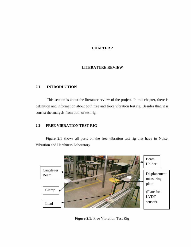
2.2 FREE VIBRATION TEST RIG
Figure 2.1 shows all parts on the free vibration test rig that have in Noise,
Vibration and Harshness Laboratory.
Figure 2.1: Free Vibration Test Rig
Load
Rod
Clamp
Cantilever
Beam Displacement
measuring
plate
(Plate for
LVDT
sensor)
Beam
Holder

5
2.2.1 Definition
Free vibration test rig is used to calculate the stiffness and vibration of the beam.
It’s occurs when a system is disturbed with constant force but immediately allowed to
move without restraint. Figure 2.2 shows the schematic diagram for free vibration
operation.
Figure 2.2 : Schematic Diagram For Free Vibration
2.2.2 Tools
For free vibration experiment, there are tools needed to operate this experiment.
The tools are :
i. Cantilever beam
ii. Load rod
iii. Mass (5N, 10N and above)
iv. LVDT sensor
v. Displacement measuring plate
vi. Computer
vii. Software (QuickDAQ)

6
2.2.3 Procedure
There are procedures to conduct this experiment. The procedures are :
i. Make sure the cantilever beam is fixed to clamped support.
ii. Decide on the mass to be used for loading the beam. The mass is usually
at 5N, 10N and above.
iii. Insert the loading rod through hole at the centre of the mass.
iv. Setting the LVDT sensor on the displacement measuring plate and make
sure computer is ready for record the data.
v. Make a force on end of the beam and make sure the force is constant
when repeat the experiment using different mass.
vi. Record the data on the computer.
2.3 FORCE VIBRATION TEST RIG
Figure 2.3 shows all parts on the force vibration test rig that have in Noise,
Vibration and Harshness Laboratory.
Figure 2.3: Force Vibration Test Rig
Signal
Box
Motor
Simply
Supported
Beam
Clamp
Unbalanced
Rotater
Applied
Mass

7
2.3.1 Definition
Forced vibration test rig is used to calculate the stiffness and vibration of the
simply supported beam. It’s occurring when the beam has unbalanced force. Figure 2.4
shows the schematic diagram for force vibration operation.
Figure 2.4 : Schematic Diagram For Force Vibration
2.3.2 Tools
For force vibration experiment, there are tools needed to operate this experiment.
The tools are :
i. Simply supported beam
ii. Clamp
iii. Rotate unbalance
iv. Motor
v. Signal box
vi. LVDT sensor
vii. Software (QuickDAQ)

8
2.3.3 Procedure
There are procedures to conduct this experiment. The procedures are :
i. Make sure the simply supported beam is fixed to clamped support.
ii. Make sure the unbalance rotating is centre of the beam.
iii. Decide on the RPM for the motor to rotate the unbalance rotating.
iv. Setting the LVDT sensor and make sure computer is ready for record the
data.
v. Start the motor to the given RPM to make the unbalanced force to the
beam and repeatedly with different RPM.
vi. Record the data on the computer.
2.4 ANALYSIS
2.4.1 The Different of Free and Force Vibration Test Rig
There are a lots of different between free and force vibration test rig. The
different are :
a. Different of the beams.
i. Free Vibration Test Rig used Cantilever beam.
ii. Force Vibration Test Rig used Simply Supported beam.
b. The load.
i. Free Vibration Test Rig used different mass of load (Load changes).
ii. Force Vibration Test Rig used constant mass of load (weight of
motor, unbalance rotating is calculate and same repeatedly).
c. Force Applied.
i. Free Vibration Test Rig used static force (Constant).
ii. Force Vibration Test Rig used unbalanced force (RPM changes).

9
2.4.2 The Similarity of Free and Force Vibration Test Rig
The similarity of both test rig is their objective of the experiment that is the
stiffness of the beam. Their objective are :
i. Get frequency from the data on the computer.
ii. Period of vibration. (How much second in 1 cycle)
2.4.3 Conclusion from Analysis
From the analysis, I decide to make the design of test rig use simply supported
beam that can operate both of free and force vibration experiment. Furthermore, the
design can use more type of beam like round ,triangle, and rectangle beam.
2.5 FABRICATION PLANNING PROCESS
2.5.1 Lathe
A lathe is a machine tool which turns cylindrical material, touches a cutting tool
to it, and cuts the material. A material is firmly fixed to the chuck of a lathe. The lathe is
switched on and the chuck is rotated. And since the table which fixed the byte can be
moved in the vertical direction and the right-and-left direction by operating some
handles.
In order to get an efficient process and beautiful surface at the lathe machining, it
is important to adjust a rotating speed, a cutting depth and a sending speed as shown in
Figure 2.5. I plan to use lathe machine for the clamp of my project. I use it to make a
facing and material remove to get an actual dimension.

10
Figure 2.5: Important element of lathe machine
Source: nmri
2.5.2 Milling
Milling is the most common form of machining, a material removal process,
which can create a variety of features on a part by cutting away the unwanted material.
The milling process requires a milling machine, workpiece, fixture, and cutter. The
workpiece is a piece of pre-shaped material that is secured to the fixture, which itself is
attached to a platform inside the milling machine. The cutter is a cutting tool with sharp
teeth that is also secured in the milling machine and rotates at high speeds. By feeding
the workpiece into the rotating cutter, material is cut away from this workpiece in the
form of small chips to create the desired shape. Milling is typically used to produce parts
that are not axially symmetric and have many features, such as holes, slots, pockets, and
even three dimensional surface contours.
I plan to make unbalance rotator and beam holder using a conventional milling
machine. Figure 2.6 below is an example of milling process.

11
Figure 2.6: Slot cut
Source: Custompartnet
2.5.3 Drilling
There are many machines capable and used to drill, ream or thread holes in a
part. Drilling is the manufacturing process where a round hole is created within a
workpiece or enlarged by rotating an end cutting tool, a drill. For this project, I plan to
make a hole for screw to hold the beam neatly. Figure 2.7 below show the drilling
process.
Figure 2.7: Drilling process

12
2.5.4 Threading
Thread cutting is cutting of helical turns of threads out of the tapping that is size
of hole or bolt in order to create screwed connections. Figure 2.8 show the process of
threading. The size of thread tools that usually use are M5, M6, M8, and M10. Figure
2.9 shows the types of thread tools.
Figure 2.8 : Thread cutting
Figure 2.9 : Tools of Threading

13
A complete screwed connection requires an internal thread and a matching
external thread as a counterpart. For this process, I plan to make thread for all parts of
my project to enable the screws.

CHAPTER 3
METHODOLOGY
3.1 INTRODUCTION
Chapter 3 is about the methodology that has been used to fabricate the
combination of free and force vibration test rig. In this chapter, a project flow chart is
defined. Figure 3.1 shows the flow chart in my project. The information that included is
establishing target specification, design concept, select final design concept, searching
material for the product and fabrication of the product. It also allows others to replicate
our study and run new and different studies that are based on our methodology.
Figure 3.1: Flow Chart

15
The project starts identify the problem. It is a first step for the project flow in
order to find the problem in current product. This step helps to create a different design
to improve the product. After identify the problem for the project, project continues with
identify the objective. The objective is very important in every work because every
procedure to make a project will depend on it. It will help to know the main point to
make the project success or not.
The project continues with identify the scope of the project because this scope
can help the progress to create the new product design for the project and to make sure
the method chose will be within the range of achievable objective. Next continue it with
literature review and research about the title. This consist a review of the existing test rig
design. These tasks have been done through research on the internet.
From the flow chart, start to design new concept. Then improve the design. Try to
come with several concepts. Then compare the criteria from each design which are the
best. If the best design chosen still needed to be improved go back to the previous step.
If no improvement is needed go to next step. Produce the drawing together with
dimension of the product and the type of materials needed. After completing the
previous task, start the fabrication process. Gather the parts needed for the project to
proceeds the fabrication process.
Here come the testing and evaluation process. The test rig will be test to see if it
full fills the requirement such as safety, ability and strength. During the testing, if a
problem occurs, the process of fabrication test rig will step back to the previous process.
The reason to step back is to fix the error. After all the parts had been joined together
and no error, here comes the phase of result and discussion. In this part, how the test rig
functions will be informs. Beside, how to achieve objective and solve problem statement
of the project will be discuss in this phase.

16
3.2 PROCESS FLOW
Table 3.1 shows below the process flow of making the combination of free and
force vibration test rig. The manufacturing process consists of 5 phases.
Table 3.1: Process flow
PHASE TITLE
Phase 1 Establish target specification.
Phase 2 Design concept.
Phase 3 Select final design.
Phase 4 Searching material for the product.
Phase 5 Fabrication of the product.

17
3.3 PHASE 1 - ESTABLISH TARGET SPECIFICATION
After the investigation of the objective, criteria selection will be developed.
Criteria selection here means the criteria that what people will look on the product. It is
focus on the existing test rig on the laboratory. Then, when the new product is done,
compare it with the existing test rig on the laboratory. The new good design should have
better criteria than the product on the market.
This is the criteria that I had to use to the new design for the combination of free
and force vibration test rig.
a. Easy to use
b. Safety
c. Durable / long life time
d. Lightweight
e. Nice design
f. Low cost
g. Strong
h. High resistance to corrosion
3.4 PHASE 2 - DESIGN CONCEPT
The purpose of this project is to design the combination of free and force
vibration test rig that can operate both experiment on one test rig. It is also should look
more efficient than existing test rig on the laboratory. The motivation for this project is
to improve the design of the combination of free and force vibration test rig that can use
any shape of beam. So the new design should have shape that various beam can through
the part. The parts are clamps, unbalance rotator and beam holder. Furthermore, the test
rig should be able to operate both free and force vibration experiment easily.
18
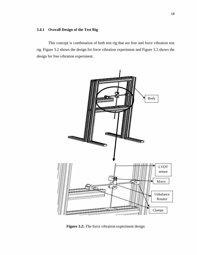
3.4.1 Overall Design of the Test Rig
This concept is combination of both test rig that are free and force vibration test
rig. Figure 3.2 shows the design for force vibration experiment and Figure 3.3 shows the
design for free vibration experiment.
Figure 3.2: The force vibration experiment design
LVDT
sensor
Motor
Unbalance
Rotator
Clamps
Body

19
Figure 3.3: The free vibration experiment design
Body
LVDT
sensor
Clamps
Simply
Supported
Beam
Displacement
Measuring
Plate

20
Both experiments are operates on one test rig. The part that should be change are
unbalance rotator and beam holder. When the force vibration experiment starting, the
part that should have are unbalance rotator, clamps, rod and beam. If the experiment is
change to the free vibration experiment, the part that should change is unbalance rotator
to the beam holder. So, the design of parts can make the experiment change easily and
can use various shape of beam.

21
3.4.2 Design Concept 1
This concept can hold the various type of beam tightly.
(a)
(b)
Figure 3.4: The drawing of unbalance rotator; a) 3D drawing and b) orthographic
drawing
Top View
Front View Side View

22
(a)
(b)
Figure 3.5: The drawing of clamp; a) 3D drawing and b) orthographic drawing
Top View
Front View Side View

23
(a)
(b)
Figure 3.6: The drawing of beam holder; a) 3D drawing and b) orthographic drawing
Side View Front View
Top View

24
3.4.3 Design Concept 2
This concept can hold the various shape of beam tightly and has simple design.
(a)
(b)
Figure 3.7: The drawing of unbalance rotator; a) 3D drawing and b) orthographic
drawing
Top View
Front View Side View