
Design and Evaluation of a 42-V Automotive Alternator With
11
Design and Evaluation of a 42-V Automotive Alternator With Integrated Switched-Mode Rectifier Citation Tang, Sai Chun et al. “Design and Evaluation of a 42-V Automotive Alternator With Integrated Switched-Mode Rectifier.” IEEE Transactions on Energy Conversion 25.4 (2010): 983–992. Web. 30 Mar. 2012. © 2010 Institute of Electrical and Electronics Engineers As Published http://dx.doi.org/10.1109/tec.2010.2050774 Publisher Institute of Electrical and Electronics Engineers (IEEE) Version Final published version Accessed Thu Apr 04 20:32:28 EDT 2019 Citable Link http://hdl.handle.net/1721.1/69902 Terms of Use Article is made available in accordance with the publisher's policy and may be subject to US copyright law. Please refer to the publisher's site for terms of use. Detailed Terms The MIT Faculty has made this article openly available. Please share how this access benefits you. Your story matters.
Transcript of Design and Evaluation of a 42-V Automotive Alternator With

Design and Evaluation of a 42-V Automotive AlternatorWith Integrated Switched-Mode Rectifier
Citation Tang, Sai Chun et al. “Design and Evaluation of a 42-VAutomotive Alternator With Integrated Switched-Mode Rectifier.”IEEE Transactions on Energy Conversion 25.4 (2010): 983–992.Web. 30 Mar. 2012. © 2010 Institute of Electrical and ElectronicsEngineers
As Published http://dx.doi.org/10.1109/tec.2010.2050774
Publisher Institute of Electrical and Electronics Engineers (IEEE)
Version Final published version
Accessed Thu Apr 04 20:32:28 EDT 2019
Citable Link http://hdl.handle.net/1721.1/69902
Terms of Use Article is made available in accordance with the publisher's policyand may be subject to US copyright law. Please refer to thepublisher's site for terms of use.
Detailed Terms
The MIT Faculty has made this article openly available. Please sharehow this access benefits you. Your story matters.
IEEE TRANSACTIONS ON ENERGY CONVERSION, VOL. 25, NO. 4, DECEMBER 2010 983
Design and Evaluation of a 42-V AutomotiveAlternator With Integrated Switched-Mode
RectifierSai Chun Tang, Member, IEEE, David M. Otten, Thomas A. Keim, and David J. Perreault, Senior Member, IEEE
Abstract—This paper presents techniques for the design of high-power Lundell alternators with integrated switched-mode recti-fiers. A multisection stator winding and interleaved rectifier ar-rangement is introduced that enables high power levels to beachieved using small semiconductor devices, and which greatlyreduces the output filter capacitor requirements. We also demon-strate control methods suited for this interleaved system. In addi-tion to accurate closed-loop output voltage control, we introducemethods to provide (partial) synchronous rectification for reducedloss, and to provide tight load-dump transient control. The pro-posed technology is validated in the design and experimental eval-uation of a 42-V, 3.4-kW alternator with fully integrated powerelectronics and controls. The prototype alternator achieves approx-imately a factor of 2.1 increase in power and 1.6 increase in powerdensity as compared to a conventional diode-rectified alternator.
Index Terms—Integrated switched-mode rectifiers (SMRs),interleaved rectifier, 42-V automotive alternator, load-dumpcontrol.
I. INTRODUCTION
THERE is an emerging need for automotive generators thatcan provide higher output power and power density, im-
proved efficiency, and better transient response (including load-dump suppression.) Moreover, there is an interest in developingelectrical systems at a higher voltage (42 V) to better accom-modate more electrical power in automobiles, and to achieveeconomies available through tighter suppression of overvoltagetransients. These challenges have motivated a variety of researchinto automotive alternator design in recent years (e.g., [1]–[26]).
Earlier work has shown that switched-mode rectification cou-pled with appropriate controls can provide dramatic improve-ments in the power capability, efficiency, and transient responseof both Lundell and permanent magnet alternators [10]–[19],[24]–[26]. This paper, an extended version of [44], carries this
Manuscript received October 11, 2009; revised February 11, 2010; acceptedMarch 27, 2010. Date of publication August 30, 2010; date of current versionNovember 19, 2010. This work was supported in part by the member com-panies of the Massachusetts Institute of Technology/Industry Consortium onAdvanced Automotive Electrical/Electronic Components and Systems. Paperno. TEC-00436-2009.
S. C. Tang is with the Focused Ultrasound Laboratory, Brigham andWomen’s Hospital, Harvard Medical School, Boston, MA 02466 USA (e-mail:[email protected]).
D. M. Otten, T. A. Keim, and D. J. Perreault are with the Laboratory forElectromagnetic and Electronic System, Massachusetts Institute of Technol-ogy, Cambridge, MA 02136 USA (e-mail: [email protected]; [email protected];[email protected]).
Color versions of one or more of the figures in this paper are available onlineat http://ieeexplore.ieee.org.
Digital Object Identifier 10.1109/TEC.2010.2050774
strategy forward. We present the design and experimental evalu-ation of a high-power 42-V Lundell alternator having the powerelectronics and control circuitry fully integrated with the ma-chine. The new design is shown to provide ∼100% increase inoutput power and power density over a conventional alterna-tor design, along with significant improvements in load-dumptransient performance. To achieve this, we introduce a multisec-tion winding and interleaved rectifier arrangement that enableshigh power levels to be achieved using small semiconductordevices, and which greatly reduces the output filter capacitorrequirements. We also demonstrate control methods suited tothis interleaved system. In addition to accurate closed-loop out-put voltage control, we introduce means to provide (partial)synchronous rectification for reduced loss, and demonstrate theability to achieve tight load-dump transient control within therequirements of 42-V electrical systems [27].
The paper is organized as follows: Section II reviews thegeneral principles underlying the alternator design, and in-troduces the interleaved winding and switched-mode rectifier(SMR) structure we propose. The physical construction of thealternator system and integrated electronics is also described.Section III describes the control approach utilized with the inter-leaved architecture. Means for providing output voltage controlare described, along with means for implementing synchronousrectification of the active devices. Experimental results demon-strating the efficacy of the control implementation are also pre-sented. The load-dump protection control scheme implementedin the system is also described, along with experimental re-sults demonstrating the ability to meet the requirements of 42-Vsystems. Finally, Section IV concludes the paper.
II. SYSTEM CONFIGURATION
A. Switched-Mode Rectification and Load-Matching Control
Conventional three-phase Lundell alternators employ a diodebridge to rectify the generated ac voltages, and regulate the out-put voltage via field control. By exchanging the diodes in thebottom half of the rectifier bridge for active devices such aspower MOSFETs, a semibridge SMR is obtained (see Fig. 1).The SMR provides additional means of controlling the alterna-tor. As shown in [10] and elsewhere, by modulating the switcheswith an appropriate duty ratio (at a high frequency compared tothe machine electrical frequency), the alternator output charac-teristics can be matched to the output in a manner that providesgreatly increased power capability and efficiency across speedand power.
0885-8969/$26.00 © 2010 IEEE

984 IEEE TRANSACTIONS ON ENERGY CONVERSION, VOL. 25, NO. 4, DECEMBER 2010
Fig. 1. Alternator with a semibridge SMR.
As shown in [10], the output power of an alternator with thisSMR can be found as
Pout =3 (1 − d) Vo
π
√(kωif )2 −
(2(1−d)VO
π
)2
ωLS(1)
wherePout alternator output power;d duty ratio of the active switches;Ls synchronous inductance of the stator winding;ω alternator angular electrical frequency;if alternator field current;k machine constant (line-neutral back electromotive
force (EMF) voltage magnitude Vs = kωif ).To obtain improved performance, duty ratio d is controlled
up to a maximum value that provides load matching of thealternator [maximizing Pout in (1)]
dmatch = 1 −√
2πk
4Voωif . (2)
By selecting appropriate combinations of duty ratio and fieldcurrent, the alternator output power can be controlled up to amaximum that is a function of the alternator speed. The ma-chine stator winding (which influences k and Ls) is selectedto provide the desired capability for a specified output voltageVo (e.g., 14 or 42 V)1. Fig. 2 shows the output power capabil-ity for the prototype Lundell machine (for an appropriate statorwinding) with both diode rectification and load-matched op-eration (as with switched-mode rectification). As can be seen,the additional flexibility provided by the SMR yields tremen-dous improvements in output power capability across the speedrange. Moreover, as shown in [10], this can be achieved at higherefficiency and lower operating temperatures.
B. Interleaved Alternator Design
While the use of switched-mode rectification offers major op-portunities, it also poses some practical challenges. One issue
1Neglecting device drops and other second-order effects, the same powercapability can be achieved at any specified output voltage Vo by an appropriaterewinding of the stator.
Fig. 2. Alternator power capability versus speed for diode rectification and forload matching control (e.g., with a SMR). Measured curves are for the alternatormachine used in the prototype.
to be addressed is the pulsating ripple current at the output ofthe SMR . Unlike a diode rectifier, the output current of theSMR of Fig. 1 pulsates at the switching frequency, yielding anrms ripple current into the rectifier output capacitor that is onthe order of Io(d/(1 − d))1/2 , where Io is the average alterna-tor output current. Low equivalent-series-resistance capacitorswith high ripple-current rating are, therefore, required to absorbthis ripple current and contribute to electromagnetic interference(EMI) filtering. This is certainly achievable in a small volumeusing film or multilayer ceramic capacitors (see, e.g., [10]), butdoes represent a significant cost element. A second challengerelates to sizing of the semiconductor switches. At 14 V out-put, reasonably high-power alternators can be implemented withsingle-die plastic-packaged devices, owing to the wide availabil-ity of low-resistance 30- and 20-V MOSFETs for low-voltageapplications. (we assume the use of active load-dump controltechniques such as those demonstrated here or in [10] to enableuse of low-voltage MOSFETs. Partly countering the advantageof MOSFETs at 14 V is the relatively worse performance ofdiodes at 14 V). At 42 V output, however, it is more difficultto realize the circuit of Fig. 1 without resorting to paralleleddevices or devices modules (as used in [10]), especially whenseeking to achieve high output power and temperature ratings.
Here, we demonstrate a design strategy that addresses both ofthe aforementioned challenges. Instead of the design of Fig. 1,we employ an interleaved machine and rectifier configuration,as illustrated in Fig. 3. In this approach, the system is con-structed from a number NC of small rectifier cells connected inparallel, with each cell fed from a separate isolated three-phasestator winding. The total system size and rating remains es-sentially unchanged, but utilizes more and smaller devices andwindings. The switching patterns of the SMR cells are identical,but are each shifted in time from the other cells by TSW /NC ,where TSW is the SMR switching period. As will be shown, thisprovides significant advantages in filtering of the output. In-terleaving has been applied earlier in a variety of applications,including dc–dc converters [28], [29], rectifiers [30], [31], andeven in alternators [5] (albeit with different operating conditionsand design objectives).
TANG et al.: DESIGN AND EVALUATION OF A 42-V AUTOMOTIVE ALTERNATOR WITH INTEGRATED SWITCHED-MODE RECTIFIER 985
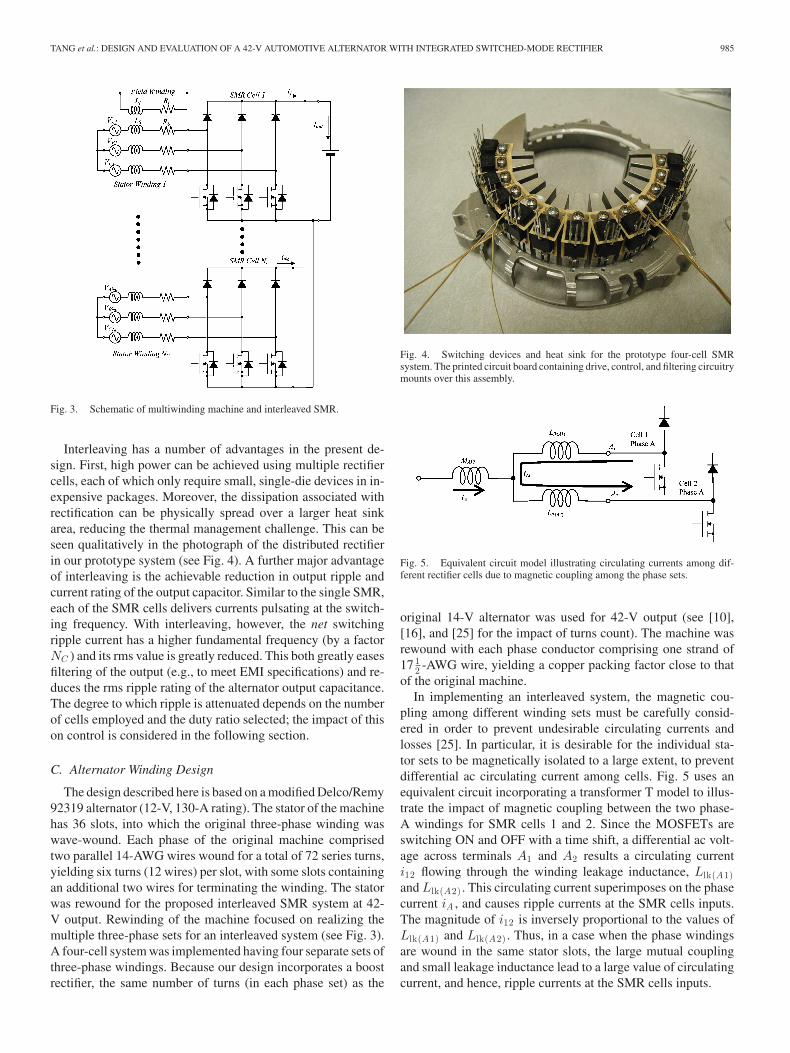
Fig. 3. Schematic of multiwinding machine and interleaved SMR.
Interleaving has a number of advantages in the present de-sign. First, high power can be achieved using multiple rectifiercells, each of which only require small, single-die devices in in-expensive packages. Moreover, the dissipation associated withrectification can be physically spread over a larger heat sinkarea, reducing the thermal management challenge. This can beseen qualitatively in the photograph of the distributed rectifierin our prototype system (see Fig. 4). A further major advantageof interleaving is the achievable reduction in output ripple andcurrent rating of the output capacitor. Similar to the single SMR,each of the SMR cells delivers currents pulsating at the switch-ing frequency. With interleaving, however, the net switchingripple current has a higher fundamental frequency (by a factorNC ) and its rms value is greatly reduced. This both greatly easesfiltering of the output (e.g., to meet EMI specifications) and re-duces the rms ripple rating of the alternator output capacitance.The degree to which ripple is attenuated depends on the numberof cells employed and the duty ratio selected; the impact of thison control is considered in the following section.
C. Alternator Winding Design
The design described here is based on a modified Delco/Remy92319 alternator (12-V, 130-A rating). The stator of the machinehas 36 slots, into which the original three-phase winding waswave-wound. Each phase of the original machine comprisedtwo parallel 14-AWG wires wound for a total of 72 series turns,yielding six turns (12 wires) per slot, with some slots containingan additional two wires for terminating the winding. The statorwas rewound for the proposed interleaved SMR system at 42-V output. Rewinding of the machine focused on realizing themultiple three-phase sets for an interleaved system (see Fig. 3).A four-cell system was implemented having four separate sets ofthree-phase windings. Because our design incorporates a boostrectifier, the same number of turns (in each phase set) as the
Fig. 4. Switching devices and heat sink for the prototype four-cell SMRsystem. The printed circuit board containing drive, control, and filtering circuitrymounts over this assembly.
Fig. 5. Equivalent circuit model illustrating circulating currents among dif-ferent rectifier cells due to magnetic coupling among the phase sets.
original 14-V alternator was used for 42-V output (see [10],[16], and [25] for the impact of turns count). The machine wasrewound with each phase conductor comprising one strand of17 1
2 -AWG wire, yielding a copper packing factor close to thatof the original machine.
In implementing an interleaved system, the magnetic cou-pling among different winding sets must be carefully consid-ered in order to prevent undesirable circulating currents andlosses [25]. In particular, it is desirable for the individual sta-tor sets to be magnetically isolated to a large extent, to preventdifferential ac circulating current among cells. Fig. 5 uses anequivalent circuit incorporating a transformer T model to illus-trate the impact of magnetic coupling between the two phase-A windings for SMR cells 1 and 2. Since the MOSFETs areswitching ON and OFF with a time shift, a differential ac volt-age across terminals A1 and A2 results a circulating currenti12 flowing through the winding leakage inductance, Llk(A1)and Llk(A2) . This circulating current superimposes on the phasecurrent iA , and causes ripple currents at the SMR cells inputs.The magnitude of i12 is inversely proportional to the values ofLlk(A1) and Llk(A2) . Thus, in a case when the phase windingsare wound in the same stator slots, the large mutual couplingand small leakage inductance lead to a large value of circulatingcurrent, and hence, ripple currents at the SMR cells inputs.

986 IEEE TRANSACTIONS ON ENERGY CONVERSION, VOL. 25, NO. 4, DECEMBER 2010
Fig. 6. Stator winding configuration for the four-SMR-cell alternator system. Each winding comprises 72 series turns made with 17 12 -AWG wire (48 wires per
slot). Adjacent sectors having different phase sets share only one slot, limiting magnetic coupling to a small value [25].
To address the issue of magnetic coupling, the four sets ofwindings were wound in four separate sectors of the machine,as illustrated in Fig. 6. Each phase winding occupies a quadrantof the stator spanning nine stator teeth. Because the number ofslots for a phase winding is an odd number, windings of eachphase in adjacent sectors share one stator slot. For example, asillustrated in Fig. 6, the two phase-A windings for SMR cells 1and 2 share slot 10. As analyzed in detail in [25] and validatedexperimentally, this winding strategy limits magnetic couplingof different phase sets to a few percent, producing large leakageinductance and eliminating practical concerns about circulatingcurrent. The only disadvantage observed in this highly separatedwinding scheme is that any mechanical offset in the position ofthe rotor from the true center of the stator can yield differences ingap (and hence back EMF) among different phase sets. The backEMF variations that were encountered in practice were only onthe order of 5%, however, which was found to be acceptable.
D. Rectifier Design and Integration
The aforementioned rewound machine has been coupled witha four-cell (NC = 4) SMR (see Fig. 3) to realize a 3.4-kW, 42-Valternator. This alternator has the power electronics and controlcircuitry fully integrated into the machine. To accommodatethe prototype SMR, heat sink, and sensors, the alternator casewas extended by approximately 4 cm (roughly by a factor of1.3). As the redesigned alternator achieves a factor of 2.1 in-crease in output power (see Fig. 2), we have achieved more thana factor of 1.6 improvement in power density. (Based on oursubsequent study, we believe that the rectifier could be incorpo-rated with no increase in case length, promising over a factor of2 improvement in power density.) A photograph of the proto-type alternator (with thermocouples attached and internal nodevoltages brought out) is shown in Fig. 7.
Based on our design studies (including [17] and [23]–[26]), itis expected that a three-cell interleaved design would have beenadequate for meeting the target performance and semiconduc-tor thermal requirements to ambient temperatures beyond 85 ◦C.However, we developed the four-cell design to make better useof the available heat sink area and achieve higher tempera-
Fig. 7. The prototype four-cell alternator. The 42-V alternator and powerelectronics are completely integrated. Numerous voltages and temperatures arebrought out for evaluation purposes.
ture capability. Each of the four cells utilizes three IRFB4310MOSFETs (100-V, 5.6-mΩ, T0-220 package) and three30CTQ100 Schottky diode pairs (100-V, 2 × 30 A, T0-220package), locally bypassed with three 0.47-μF ceramic capaci-tors. Note that the voltage ratings of the semiconductor deviceswere selected quite conservatively, as testing demonstrated thatvoltage transients could be limited below 56 V, even under load-dump conditions (see Section III). The MOSFETs are drivenfrom IR4426S gate drivers via 4.7-Ω series resistors. Controlis provided by a MC68HC908 microcontroller, which controlsboth the SMR and provides pulsewidth modulated (PWM) fieldcontrol. The SMR operates at a switching frequency of 100 kHz,representing a reasonable tradeoff between switching and con-duction loss, while the field is pulsewidth modulated at 12.5 kHz.
A custom aluminum heat sink was designed based on thermalmodels for the alternator developed in [17] and [23]; a photo-graph of the devices mounted to the heat sink is shown in Fig. 4.Acceptable temperature rises at the device cases of less than50 ◦C were found for all operating conditions evaluated.
TANG et al.: DESIGN AND EVALUATION OF A 42-V AUTOMOTIVE ALTERNATOR WITH INTEGRATED SWITCHED-MODE RECTIFIER 987
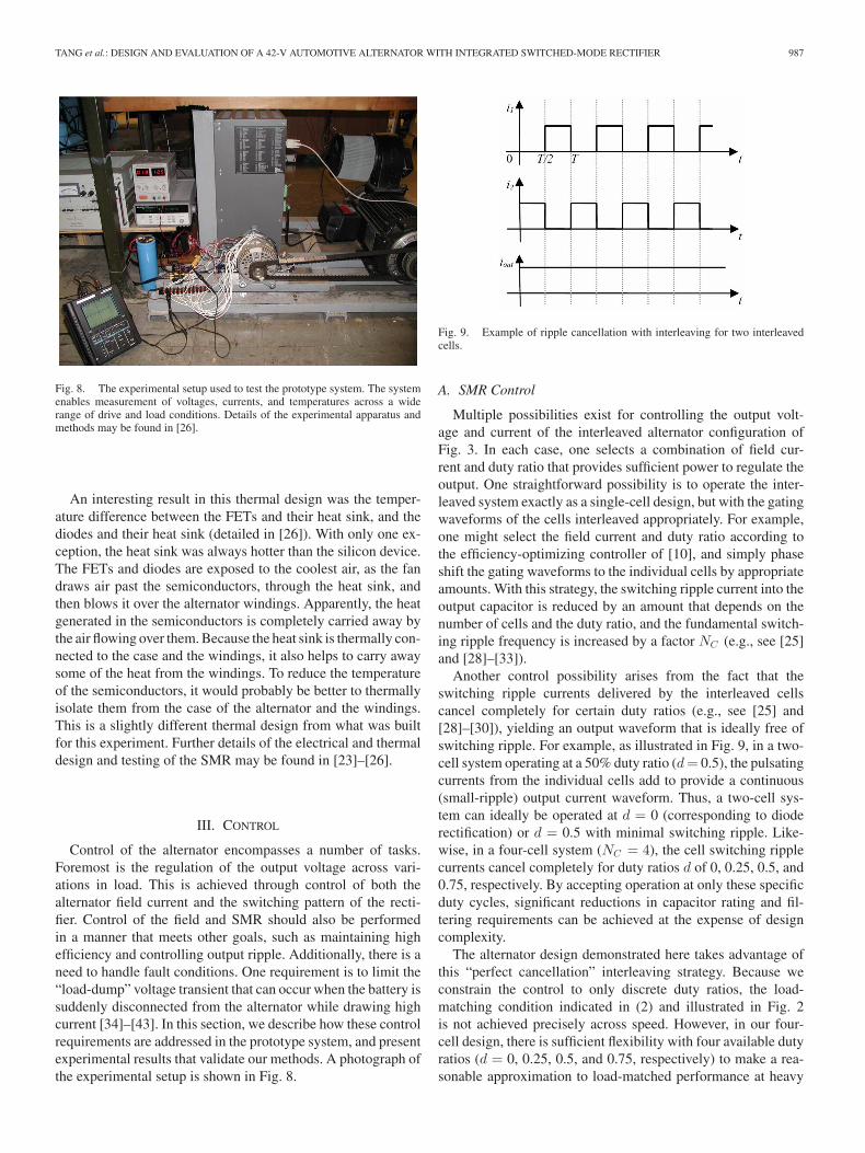
Fig. 8. The experimental setup used to test the prototype system. The systemenables measurement of voltages, currents, and temperatures across a widerange of drive and load conditions. Details of the experimental apparatus andmethods may be found in [26].
An interesting result in this thermal design was the temper-ature difference between the FETs and their heat sink, and thediodes and their heat sink (detailed in [26]). With only one ex-ception, the heat sink was always hotter than the silicon device.The FETs and diodes are exposed to the coolest air, as the fandraws air past the semiconductors, through the heat sink, andthen blows it over the alternator windings. Apparently, the heatgenerated in the semiconductors is completely carried away bythe air flowing over them. Because the heat sink is thermally con-nected to the case and the windings, it also helps to carry awaysome of the heat from the windings. To reduce the temperatureof the semiconductors, it would probably be better to thermallyisolate them from the case of the alternator and the windings.This is a slightly different thermal design from what was builtfor this experiment. Further details of the electrical and thermaldesign and testing of the SMR may be found in [23]–[26].
III. CONTROL
Control of the alternator encompasses a number of tasks.Foremost is the regulation of the output voltage across vari-ations in load. This is achieved through control of both thealternator field current and the switching pattern of the recti-fier. Control of the field and SMR should also be performedin a manner that meets other goals, such as maintaining highefficiency and controlling output ripple. Additionally, there is aneed to handle fault conditions. One requirement is to limit the“load-dump” voltage transient that can occur when the battery issuddenly disconnected from the alternator while drawing highcurrent [34]–[43]. In this section, we describe how these controlrequirements are addressed in the prototype system, and presentexperimental results that validate our methods. A photograph ofthe experimental setup is shown in Fig. 8.
Fig. 9. Example of ripple cancellation with interleaving for two interleavedcells.
A. SMR Control
Multiple possibilities exist for controlling the output volt-age and current of the interleaved alternator configuration ofFig. 3. In each case, one selects a combination of field cur-rent and duty ratio that provides sufficient power to regulate theoutput. One straightforward possibility is to operate the inter-leaved system exactly as a single-cell design, but with the gatingwaveforms of the cells interleaved appropriately. For example,one might select the field current and duty ratio according tothe efficiency-optimizing controller of [10], and simply phaseshift the gating waveforms to the individual cells by appropriateamounts. With this strategy, the switching ripple current into theoutput capacitor is reduced by an amount that depends on thenumber of cells and the duty ratio, and the fundamental switch-ing ripple frequency is increased by a factor NC (e.g., see [25]and [28]–[33]).
Another control possibility arises from the fact that theswitching ripple currents delivered by the interleaved cellscancel completely for certain duty ratios (e.g., see [25] and[28]–[30]), yielding an output waveform that is ideally free ofswitching ripple. For example, as illustrated in Fig. 9, in a two-cell system operating at a 50% duty ratio (d = 0.5), the pulsatingcurrents from the individual cells add to provide a continuous(small-ripple) output current waveform. Thus, a two-cell sys-tem can ideally be operated at d = 0 (corresponding to dioderectification) or d = 0.5 with minimal switching ripple. Like-wise, in a four-cell system (NC = 4), the cell switching ripplecurrents cancel completely for duty ratios d of 0, 0.25, 0.5, and0.75, respectively. By accepting operation at only these specificduty cycles, significant reductions in capacitor rating and fil-tering requirements can be achieved at the expense of designcomplexity.
The alternator design demonstrated here takes advantage ofthis “perfect cancellation” interleaving strategy. Because weconstrain the control to only discrete duty ratios, the load-matching condition indicated in (2) and illustrated in Fig. 2is not achieved precisely across speed. However, in our four-cell design, there is sufficient flexibility with four available dutyratios (d = 0, 0.25, 0.5, and 0.75, respectively) to make a rea-sonable approximation to load-matched performance at heavy
988 IEEE TRANSACTIONS ON ENERGY CONVERSION, VOL. 25, NO. 4, DECEMBER 2010
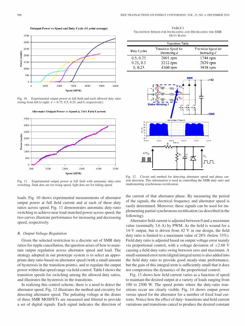
Fig. 10. Experimental output power at full field and each allowed duty ratio(rising from left to right: d = 0.75, 0.5, 0.25, and 0, respectively).
Fig. 11. Experimental output power at full field with automatic duty-ratioswitching. Dark dots are for rising speed, light dots are for falling speed.
loads. Fig. 10 shows experimental measurements of alternatoroutput power at full field current and at each of these dutyratios across speed. Fig. 11 demonstrates automatic duty-ratioswitching to achieve near load-matched power across speed; thetwo curves illustrate performance for increasing and decreasingspeed, respectively.
B. Output Voltage Regulation
Given the selected restriction to a discrete set of SMR dutyratios for ripple cancellation, the question arises of how to main-tain output regulation across alternator speed and load. Thestrategy adopted in our prototype system is to select an appro-priate duty ratio based on alternator speed (with a small amountof hysteresis in the transition points), and to regulate the outputpower within that speed range via field control. Table I shows thetransition speeds for switching among the allowed duty ratios,and illustrates the hysteresis in the transitions.
In realizing this control scheme, there is a need to detect thealternator speed. Fig. 12 illustrates the method and circuitry fordetecting alternator speed. The pulsating voltage at the drainsof three SMR MOSFETs are measured and filtered to providea set of digital signals. Each signal indicates the direction of
TABLE ITRANSITION SPEEDS FOR INCREASING AND DECREASING THE SMR
DUTY RATIO
Fig. 12. Circuit and method for detecting alternator speed and phase cur-rent direction. This information is used in controlling the SMR duty ratio andimplementing synchronous rectification.
the current of that alternator phase. By measuring the periodof the signals, the electrical frequency and alternator speed iseasily determined. Moreover, these signals can be used for im-plementing partial synchronous rectification (as described in thefollowing).
Alternator field current is adjusted between 0 and a maximumvalue (nominally 3.6 A) by PWM. As the field is wound for a14-V output, but is driven from 42 V in our design, the fieldduty ratio is limited to a maximum value of 28% (below 33%).Field duty ratio is adjusted based on output voltage error mainlyvia proportional control, with a voltage deviation of ±2.68 Vcausing a field duty-ratio swing between zero and maximum. Asmall summed error term (digital integral term) is also added intothe field duty ratio to provide good steady-state performance,but the gain of this integral term is sufficiently small that it doesnot compromise the dynamics of the proportional control.
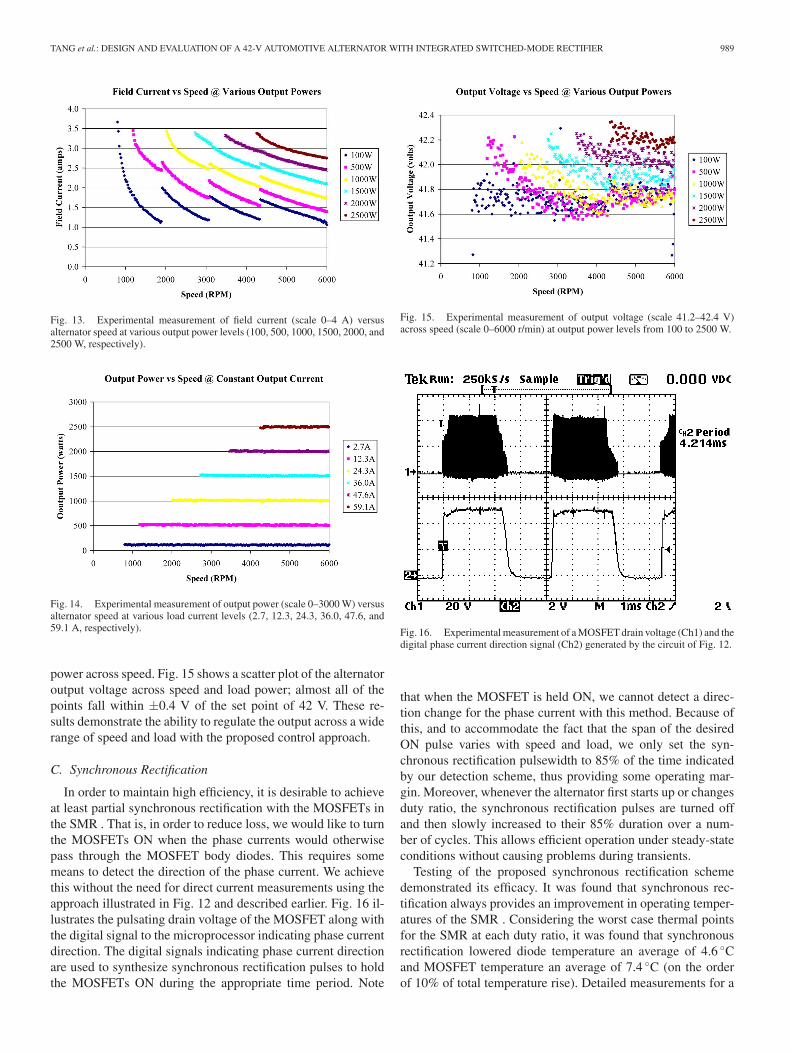
Fig. 13 shows how field current varies as a function of speedto maintain the desired output at a variety of loads ranging from100 to 2500 W. The speed points where the duty-ratio tran-sitions occur are clearly visible. Fig. 14 shows output powerversus speed for the alternator for a number of fixed load cur-rents. Notice how the effect of duty- transitions and field currentvariations and transitions cancel to produce the desired constant
TANG et al.: DESIGN AND EVALUATION OF A 42-V AUTOMOTIVE ALTERNATOR WITH INTEGRATED SWITCHED-MODE RECTIFIER 989
Fig. 13. Experimental measurement of field current (scale 0–4 A) versusalternator speed at various output power levels (100, 500, 1000, 1500, 2000, and2500 W, respectively).
Fig. 14. Experimental measurement of output power (scale 0–3000 W) versusalternator speed at various load current levels (2.7, 12.3, 24.3, 36.0, 47.6, and59.1 A, respectively).
power across speed. Fig. 15 shows a scatter plot of the alternatoroutput voltage across speed and load power; almost all of thepoints fall within ±0.4 V of the set point of 42 V. These re-sults demonstrate the ability to regulate the output across a widerange of speed and load with the proposed control approach.
C. Synchronous Rectification
In order to maintain high efficiency, it is desirable to achieveat least partial synchronous rectification with the MOSFETs inthe SMR . That is, in order to reduce loss, we would like to turnthe MOSFETs ON when the phase currents would otherwisepass through the MOSFET body diodes. This requires somemeans to detect the direction of the phase current. We achievethis without the need for direct current measurements using theapproach illustrated in Fig. 12 and described earlier. Fig. 16 il-lustrates the pulsating drain voltage of the MOSFET along withthe digital signal to the microprocessor indicating phase currentdirection. The digital signals indicating phase current directionare used to synthesize synchronous rectification pulses to holdthe MOSFETs ON during the appropriate time period. Note
Fig. 15. Experimental measurement of output voltage (scale 41.2–42.4 V)across speed (scale 0–6000 r/min) at output power levels from 100 to 2500 W.
Fig. 16. Experimental measurement of a MOSFET drain voltage (Ch1) and thedigital phase current direction signal (Ch2) generated by the circuit of Fig. 12.
that when the MOSFET is held ON, we cannot detect a direc-tion change for the phase current with this method. Because ofthis, and to accommodate the fact that the span of the desiredON pulse varies with speed and load, we only set the syn-chronous rectification pulsewidth to 85% of the time indicatedby our detection scheme, thus providing some operating mar-gin. Moreover, whenever the alternator first starts up or changesduty ratio, the synchronous rectification pulses are turned offand then slowly increased to their 85% duration over a num-ber of cycles. This allows efficient operation under steady-stateconditions without causing problems during transients.
Testing of the proposed synchronous rectification schemedemonstrated its efficacy. It was found that synchronous rec-tification always provides an improvement in operating temper-atures of the SMR . Considering the worst case thermal pointsfor the SMR at each duty ratio, it was found that synchronousrectification lowered diode temperature an average of 4.6 ◦Cand MOSFET temperature an average of 7.4 ◦C (on the orderof 10% of total temperature rise). Detailed measurements for a
990 IEEE TRANSACTIONS ON ENERGY CONVERSION, VOL. 25, NO. 4, DECEMBER 2010
variety of operating conditions may be found in [26]. As thereis no additional hardware expense and little control complexityto realizing the proposed synchronous rectification scheme, itsuse is well justified.
D. Load-Dump Transient Control
Control of load-dump transients is another important aspectof alternator design. This is particularly important in 42-V elec-trical systems, since the proposed transient limits [27] are muchtighter (on a percent overvoltage basis) than is typically achievedwith Lundell alternators (e.g., see [34]–[43]). The SMR alterna-tor can achieve significantly improved output voltage transientresponse as compared to a diode-rectified alternator [10]. Whena load dump event takes place, the output current of the alter-nator has no place to go; therefore, the output voltage buildsup. If the increase in output voltage is sensed, and the MOS-FETs in the rectifier are turned on when the voltage exceeds athreshold, the alternator current can be diverted from the outputwhile the field current is reduced, and the high-voltage transientassociated with the energy stored in the machine synchronousreactance can be eliminated. Moreover, shorting the output ofthe machine via the MOSFETs prevents the line-to-line backEMF voltage of the alternator from appearing at the rectifieroutput. The strategy undertaken is thus to detect the occurrenceof a load-dump transient overvoltage with a comparator. Whena fault is detected, the SMR MOSFETs are turned on, and thefield drive is turned off. After a minimum 300 ms delay forclearance of the fault, the alternator restarts.
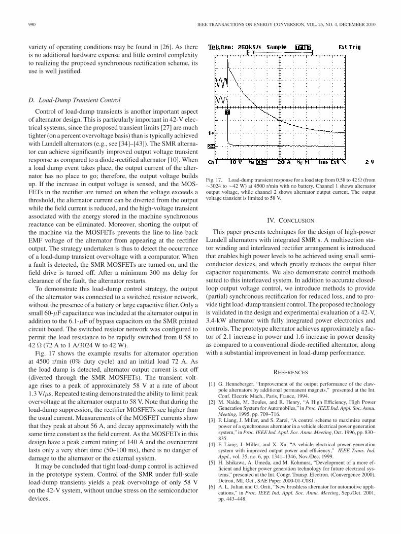
To demonstrate this load-dump control strategy, the outputof the alternator was connected to a switched resistor network,without the presence of a battery or large capacitive filter. Only asmall 60-μF capacitance was included at the alternator output inaddition to the 6.1-μF of bypass capacitors on the SMR printedcircuit board. The switched resistor network was configured topermit the load resistance to be rapidly switched from 0.58 to42 Ω (72 A to 1 A/3024 W to 42 W).
Fig. 17 shows the example results for alternator operationat 4500 r/min (0% duty cycle) and an initial load 72 A. Asthe load dump is detected, alternator output current is cut off(diverted through the SMR MOSFETs). The transient volt-age rises to a peak of approximately 58 V at a rate of about1.3 V/μs. Repeated testing demonstrated the ability to limit peakovervoltage at the alternator output to 58 V. Note that during theload-dump suppression, the rectifier MOSFETs see higher thanthe usual current. Measurements of the MOSFET currents showthat they peak at about 56 A, and decay approximately with thesame time constant as the field current. As the MOSFETs in thisdesign have a peak current rating of 140 A and the overcurrentlasts only a very short time (50–100 ms), there is no danger ofdamage to the alternator or the external system.
It may be concluded that tight load-dump control is achievedin the prototype system. Control of the SMR under full-scaleload-dump transients yields a peak overvoltage of only 58 Von the 42-V system, without undue stress on the semiconductordevices.
Fig. 17. Load-dump transient response for a load step from 0.58 to 42 Ω (from∼3024 to ∼42 W) at 4500 r/min with no battery. Channel 1 shows alternatoroutput voltage, while channel 2 shows alternator output current. The outputvoltage transient is limited to 58 V.
IV. CONCLUSION
This paper presents techniques for the design of high-powerLundell alternators with integrated SMR s. A multisection sta-tor winding and interleaved rectifier arrangement is introducedthat enables high power levels to be achieved using small semi-conductor devices, and which greatly reduces the output filtercapacitor requirements. We also demonstrate control methodssuited to this interleaved system. In addition to accurate closed-loop output voltage control, we introduce methods to provide(partial) synchronous rectification for reduced loss, and to pro-vide tight load-dump transient control. The proposed technologyis validated in the design and experimental evaluation of a 42-V,3.4-kW alternator with fully integrated power electronics andcontrols. The prototype alternator achieves approximately a fac-tor of 2.1 increase in power and 1.6 increase in power densityas compared to a conventional diode-rectified alternator, alongwith a substantial improvement in load-dump performance.
REFERENCES
[1] G. Henneberger, “Improvement of the output performance of the claw-pole alternators by additional permanent magnets,” presented at the Int.Conf. Electric Mach., Paris, France, 1994.
[2] M. Naidu, M. Boules, and R. Henry, “A High Efficiency, High PowerGeneration System for Automobiles,” in Proc. IEEE Ind. Appl. Soc. Annu.Meeting, 1995, pp. 709–716.
[3] F. Liang, J. Miller, and S. Zarei, “A control scheme to maximize outputpower of a synchronous alternator in a vehicle electrical power generationsystem,” in Proc. IEEE Ind. Appl. Soc. Annu. Meeting, Oct. 1996, pp. 830–835.
[4] F. Liang, J. Miller, and X. Xu, “A vehicle electrical power generationsystem with improved output power and efficiency,” IEEE Trans. Ind.Appl., vol. 35, no. 6, pp. 1341–1346, Nov./Dec. 1999.
[5] H. Ishikawa, A. Umeda, and M. Kohmura, “Development of a more ef-ficient and higher power generation technology for future electrical sys-tems,” presented at the Int. Congr. Transp. Electron. (Convergence 2000),Detroit, MI, Oct., SAE Paper 2000-01-C081.
[6] A. L. Julian and G. Oriti, “New brushless alternator for automotive appli-cations,” in Proc. IEEE Ind. Appl. Soc. Annu. Meeting, Sep./Oct. 2001,pp. 443–448.

TANG et al.: DESIGN AND EVALUATION OF A 42-V AUTOMOTIVE ALTERNATOR WITH INTEGRATED SWITCHED-MODE RECTIFIER 991
[7] I. Boldea, S. Scridon, and L. Tutelea, “BEGA- A biaxial excitation gen-erator for automobiles,” presented at the 7th Int. OPTIM Conf., Brasov,Romania, May 10–11, 2000.
[8] F. B. Reiter Jr., K. Rajashekara, and R. J. Krefta, “Salient pole generatorsfor belt-driven automotive alternator applications,” in Proc. IEEE Ind.Appl. Soc. Annu. Meeting, 2001, pp. 437–442.
[9] S. Scridon, I. Boldea, L. Tutelea, F. Blaabjerg, and A. E. Richie, “BEGA– A biaxial excitation generator for automobiles: Comprehensive char-acterization and test results,” IEEE Trans. Ind. Appl., vol. 41, no. 4,pp. 935–944, Jul./Aug. 2005.
[10] D. J. Perreault and V. Caliskan, “Automotive power generation and con-trol,” IEEE Trans. Power Electron., vol. 19, no. 3, pp. 618–630, May2004.
[11] J. M. Rivas, D. J. Perreault, and T. A. Keim, “Performance improvement inalternators with switched-mode rectifiers,” IEEE Trans. Energy Convers.,vol. 19, no. 3, pp. 561–568, Sep. 2004.
[12] W. L. Soong and N. Ertugrul, “Inverterless high-power interior permanent-magnet automotive alternator,” IEEE Trans. Ind. Appl., vol. 40, no. 4,pp. 1083–1091, Jul./Aug. 2004.
[13] C.-Z. Liaw, D. M. Whaley, W. L. Soong, and N. Ertugrul, “Investigationof inverterless control of interior permanent-magnet alternators,” IEEETrans. Ind. Appl., vol. 42, no. 2, pp. 536–544, Mar./Apr. 2006.
[14] C. Z. Liaw, W. L. Soong, and N. Ertugrul, “Closed-loop control andperformance of an inverterless interior PM automotive alternator,” in Proc.Conf. Power Electron. Drive Syst., 2005, pp. 343–348.
[15] C. Z. Liaw, W. L. Soong, and N. Ertugrul, “Low-speed output powerimprovement of an interior PM automotive alternator,” in Proc. IEEE Ind.Appl. Soc. Annu. Meeting, 2006, pp. 27–34.
[16] G. Hassan, D. J. Perreault, and T. A. Keim, “Design of dual-output alter-nators with switched-mode rectification,” IEEE Trans. Power Electron.,vol. 20, no. 1, pp. 164–172, Jan. 2005.
[17] S. C. Tang, T. A. Keim, and D. J. Perreault, “Thermal modeling of lundellalternators,” IEEE Trans. Energy Convers., vol. 20, no. 1, pp. 25–36, Mar.2005.
[18] L. M. Lorilla, T. A. Keim, J. H. Lang, and D. J. Perreault, “Topolo-gies for future automotive generators, Part I: Modeling and analyt-ics,” presented at the Veh. Power Propulsion Conf., Chicago, IL,Sep. 2005.
[19] L. M. Lorilla, T. A. Keim, J. H. Lang, and D. J. Perreault, “Topologiesfor future automotive generators, Part II: Optimization,” presented at theVeh. Power Propulsion Conf., Chicago, IL, Sep. 2005.
[20] D. J. Perreault, T. A. Keim, J. H. Lang, and L. M. Lorilla, “Appli-cations of power electronics in automotive power generation,” pre-sented at the SIA Int. Conf. Automotive Power Electron., Paris, France,Jun. 2006.
[21] L. M. Lorilla, T. A. Keim, J. H. Lang, and D. J. Perreault, “Foil fieldlundell alternator with rotating power electronics,” in Proc. IEEE PowerElectron. Spec. Conf., Jeju, Korea, Jun. 2006, pp. 2164–2169.
[22] S. Rees and U. Ammann, “A smart synchronous rectifier for 12 V au-tomobile alternators,” in Proc. IEEE Power Electron. Spec. Conf., 2003,pp. 1516–1521.
[23] S. C. Tang, D. J. Perreault, and T. A. Keim, “Advanced automotive powerelectronics: Thermal analysis of lundell alternator,” MIT/Ind. ConsortiumAdv. Automotive Electr./Electron. Compon. Syst., Summer 2002 ProjectRep., Sep. 2002.
[24] S. C. Tang, D. J. Perreault, and T. A. Keim, “Advanced automotivepower electronics: Switching behavior of power MOSFETs in switched-mode-rectifier for lundell alternator,” MIT/Ind. Consortium Adv. Au-tomotive Electr./Electron. Compon. Syst., Winter 2003 Project Rep.,Jan. 14, 2003.
[25] S. C. Tang, D. J. Perreault, and T. A. Keim, “Electronically-aidedpower generation and control: Design principle of interleaved switchedmode rectifier for lundell alternator,” MIT/Ind. Consortium Adv. Au-tomotive Electr./Electron. Compon. Syst., Summer 2003 Project Rep.,Aug. 21, 2003.
[26] D. Otten, “Test report: Switch mode rectifier equipped alterna-tor,” MIT Laboratory for Electromagnetic and Electronic Systems,Sep. 2006.
[27] J. M. Miller, D. Goel, D. Kaminski, H.-P. Schoner, and T. M. Jahns,“Making the case for a next generation automotive electrical system,” inProc. IEEE-SAE Int. Conf. Transp. Electron. (Convergence), Dearborn,MI, Oct.1998, pp. 41–51, SAE Paper 98C006.
[28] C. Chang and M. Knights, “Interleaving technique in distributed powerconversion systems,” IEEE Trans. Circuits Syst. I, Fundam. Theory Appl.,vol. 42, no. 5, pp. 245–251, May 1995.
[29] D. J. Perreault and J. G. Kassakian, “Distributed interleaving of paralleledpower converters,” IEEE Trans. Circuits Syst. I, Fundam. Theory Appl.,vol. 44, no. 8, pp. 728–734, Aug. 1997.
[30] B. A. Miwa, D. M. Otten, and M. F. Schlecht, “High efficiency power factorcorrection using interleaving techniques,” in Proc. IEEE Appl. PowerElectron. Conf., Boston, MA, 1992, pp. 557–568.
[31] B. A. Miwa, “Interleaved conversion techniques for high density powersupplies,” Ph.D. dissertation, Dept. Electr. Eng. Comput. Sci., MIT, Cam-bridge, MA, Jun. 1992.
[32] B. N. Singh, G. Joos, and P. Jain, “A new topology of 3-phasePWM AC/DC interleaved converter for telecommunication supply sys-tems,” in Proc. IEEE Ind. Appl. Soc. Annu. Meeting, Oct. 2000, pp.2290–2296.
[33] D. J. Perreault and J. G. Kassakian, “Design and evaluation of a cellularrectifier system with distributed control,” IEEE Trans. Ind. Electron.,vol. 46, no. 3, pp. 495–503, Jun. 1999.
[34] D. J. Perreault, K. K. Afridi, and I. A. Khan, “Automotive applications ofpower electronics,” in The Power Electronics Handbook, M. H. Rashid,Ed. New York: Academic, 2001, pp. 791–813.
[35] SAE EMI Standards Committee (1995), “Immunity to conducted tran-sients on power leads,” SAE Standard J1113/11, in SAE Handbook, Soci-ety of Automotive Engineers, Warrendale, PA, 1999.
[36] J. R. Morgan, “Transients in the automotive electrical system,” in Proc.Veh. Technol. Conf., Cleveland, OH, 1973, pp. 1–10.
[37] S. Yamamoto, O. Ozeki, T. Yamanaka, and H. Kondo, “Electrical environ-mental characteristics for automotive electronic systems,” IEEE Trans.Veh. Technol., vol. VT-32, no. 2, pp. 151–157, May 1983.
[38] S. Korn, “Automobiles need transient voltage suppression,” Power Con-vers. Intell. Motion, vol. 15, no. 2, pp. 28–31, Feb. 1989.
[39] T. Elfland, M. Manternach, A. Marshall, and J. Mings, “The load dump,”in Proc. IEEE Workshop Electron. Appl. Transp., 1990, pp. 73–78.
[40] J. D. Dimech, “Standardized automotive load dump testing,” in Proc.IEEE Int. Symp. Electromagn. Compat., 1991, pp. 355–359.
[41] P. Le Bars, “42 V load dump transient and centralised active suppression,”in Proc. Passenger Car Electr. Arch. IEE Semin., London, U.K., 2000,pp. 4/1–4/3.
[42] C. S. Namuduri, B. V. Murty, and M. G. Reynolds, “Load dump transientcontrol of a 42V automotive generator,” in Proc. IEEE Power Electron.Spec. Conf., Aachen, Germany, 2004, pp. 389–394.
[43] Z. J. Shen, S. P. Robb, F. Y. Rob, M. Fuchs, D. Berels, andK. Hampton, “Load dump protection in 42 V automotive electrical dis-tribution systems,” in Proc. IEEE Appl. Power Electron. Conf., 2001,pp. 289–295.
[44] S. C. Tang, D. M. Otten, T. A. Keim, and D. J. Perreault, “Design andevaluation of a 42 V automotive alternator with integrated switched-moderectifier,” in Proc. IEEE Veh. Power Propulsion Conf., Sep. 2007, pp. 250–258.
Sai Chun Tang (S’97–M’01) was born in HongKong in 1972. He received the B.Eng. degree (withfirst class honors), and the Ph.D. degree in elec-tronic engineering from City University of HongKong, Kowloon, Hong Kong, in 1997 and 2000,respectively.
He was a Research Fellow at the City Universityof Hong Kong. He joined the National Universityof Ireland, Galway, Ireland as a Visiting AcademicResearch Fellow in 2001, and then the Laboratoryfor Electromagnetic and Electronic Systems, Mas-
sachusetts Institute of Technology, Cambridge, in 2002. Since 2004, he hasbeen at the Focused Ultrasound Laboratory, Brigham and Women’s Hospital,Harvard Medical School, Boston, MA, where he has been involved in the de-velopment of ultrasound diagnosis devices and noninvasive treatment systemsusing high-intensity focused ultrasound. In 2008, he became a Faculty Memberat Harvard Medical School and an Instructor in radiology. His research interestsinclude high-frequency electromagnetism, low-profile power converter design,and analog electronics.

992 IEEE TRANSACTIONS ON ENERGY CONVERSION, VOL. 25, NO. 4, DECEMBER 2010
David M. Otten received the B.S. and S.M. de-grees from the Massachusetts Institute of Technology(MIT), Cambridge, in 1973 and 1974, respectively.
In 1974, he joined the Electric Power Systems En-gineering Laboratory, MIT as a Staff Engineer. Since1984, he has been a Principal Research Engineer inthe Laboratory for Electromagnetic and ElectronicSystem, MIT. His current research interests includeinstrumentation, power electronics, and the micro-mouse robot contest.
Thomas A. Keim received the D.Sc. degree fromthe Massachusetts Institute of Technology (MIT),Cambridge.
He was at MIT for several years as a Member ofthe sponsored research staff, where he was involved insuperconducting electric machines. He was for over adecade with General Electric Corporate Research andDevelopment (now known as GE Global Research),where he was involved in superconducting electricmachines and in superconducting electromagnets formedical nuclear magnetic resonance imaging. He was
a Corporate Officer and Chief Engineer at Kaman Electromagnetics Corporation(now a part of DRS Technologies, Inc.) for nearly a decade and led engineeringof multiple high-performance electromechanical and power electronics systems.Since 1998, he has again been at MIT, where he is a Principal Research Engi-neer and the Director of the MIT/Industry Consortium on Advanced AutomotiveElectrical/Electronic Components and Systems. He has authored or coauthoredmore than 45 publications in various international journals and conferences, andholds 11 patents.
David J. Perreault (S’91–M’97–SM’06) receivedthe B.S. degree from Boston University, Boston,MA, in 1989, and the S.M. and Ph.D. degrees fromthe Massachusetts Institute of Technology (MIT),Cambridge, MA, in 1991 and 1997, respectively.
In 1997, he joined the Laboratory for Electromag-netic and Electronic Systems, MIT as a PostdoctoralAssociate, and became a Research Scientist in 1999.In 2001, he joined the Department of Electrical En-gineering and Computer Science, MIT, where he iscurrently an Associate Professor. He has coauthored
four IEEE prize papers. His research interests include design, manufacturing,and control techniques for power electronics, and their use in a wide range ofapplications.
Dr. Perreault received the Richard M. Bass Outstanding Young Power Elec-tronics Engineer Award from the IEEE Power Electronics Society, an Officeof Naval Research Young Investigator Award, and the Society of AutomotiveEngineers Ralph R. Teetor Educational Award.