Design and Development of a Wide-Field Fully Cryogenic ...
24
Design and Development of a Wide-Field Fully Cryogenic Phased Array Feed for Arecibo Mitchell C. Burnett, Jakob Kunzler, Erich Nygaard, Brian D. Jeffs, Karl F. Warnick Department of Electrical and Computer Engineering Brigham Young University, Provo UT, USA Donald Campbell, German Cortes-Medellin, Stephen Parshley, Amit Vishwas Cornell Center for Astrophysics and Planetary Science Cornell University, Ithaca, NY, USA Phil Perillat and D. Anish Roshi Arecibo Observatory, Arecibo Puerto Rico, USA
Transcript of Design and Development of a Wide-Field Fully Cryogenic ...

Cornell'University.Ithaca&NY&14853,&USA&
Design and Development of a Wide-Field Fully Cryogenic Phased Array Feed for Arecibo
Mitchell C. Burnett, Jakob Kunzler, Erich Nygaard, Brian D. Jeffs, Karl F. WarnickDepartment of Electrical and Computer Engineering
Brigham Young University, Provo UT, USA
Donald Campbell, German Cortes-Medellin, Stephen Parshley, Amit VishwasCornell Center for Astrophysics and Planetary Science
Cornell University, Ithaca, NY, USA
Phil Perillat and D. Anish Roshi
Arecibo Observatory, Arecibo Puerto Rico, USA

Cornell'University.Ithaca&NY&14853,&USA&
ALPACA Grant Details• NSF Award AST-1636645• Brigham Young University, Cornell
University, UCF• 4 years, $5.8M• Cornell: PAF front-end, including
electronics, array elements, dewar, cryogenics, mechanical engineering• BYU: Overall project management,
signal downlink, digital beamformer, data handling• UCF: Site preparation, installation and
testing support.• 2.5 year funding wait over!

Cornell'University.Ithaca&NY&14853,&USA&
The PAF Narrowband Digital Beamformer
§ Repeat for each frequency channel.
§ wk is frequency dependent.
§ wk steers beam mainlobe towards(i)
+
w*1
w*3
w*M
b(i) = w y(i) H
θ
Space signalof interest
Noise :
Interference
y (i)1
y (i)3
y (i)M
n (i)1
n (i)M
s(i)
z (i)1 ���
bk (i) =wkHyk (i)

Cornell'University.Ithaca&NY&14853,&USA&
• Densely-packed simultaneous beams• Fully sample the optics-imposed
field of view• Potential for adaptive spatial
filtering to null RFI sources• Potential for beampattern shape
control to combat comay(i)
s(i)z(i)
Radio telescope dish with a phased array feed
Beamforming Capabilities

Cornell'University.Ithaca&NY&14853,&USA&
Field of view comparedto existing 7 beam ALFA receiver:
PAFS are all about survey speed and sky mapping

Cornell'University.Ithaca&NY&14853,&USA&
Performance compared to other astronomical receivers

Cornell'University.Ithaca&NY&14853,&USA&
Science Goals for ALPACA
• ALPACA design is targeted for: • HI and other long-integration, fine resolution spectral line observations• Pulsar/transient observation and parameter estimation
• Primarily a survey and mapping instrument due to wide field of view

Cornell'University.Ithaca&NY&14853,&USA&
ALPACA System Architecture
! ! ! ! ! ! ! ! !
2
3 4
1
LNA
T=80KTA
Cryostat
T=15K
Signal Conditioning
λx138
RF/O
RF/O
FO Link
Signal Conditioning
ALPACA Cryo PAFArchitecture Rev Jun, 2019
x138
Digital Beamformerx138
G= 35 dB
Te = 5K x138
IL=Flo: Fhi:
BPF
NF=3dBGmin=Gmax=
VGA
138
Test4
ADC
! ! ! ! ! ! ! ! !
2
3 4
1
Test2Test1
!!!!!!!!!
3
2 1
4
Test3
!!!!!!!!!
3
2 1
4
X"engine'F"engine'
1
Equations
German Cortes M., Nov 21, 2011, (Rev. August 7, 2015)
I. NON LINEAR FIT: FIELD INTENSITY AT APERTURE PLANE
Best fit of the near fields peak intensity at a radial distance r in wavelengths,
|Epeak(r�)| = bo + b1 ln (r� � ro) [dB] (1)
bo = �2.50745 (2)
b1 = �3.55645 (3)
ro = �1.9473 (4)
xi = !j (5)
yj =X
i
!ji xi (6)
REFERENCES
[Kathuria, 1983] Y. P. Kathuria, “ Far-Field Radiation Patterns of Elliptical Apertures and its Annulli ”, IEEETransactions on Antennas and Propagation, Vol AP-31, No. 2, March 1983, pp. 360-364.
Ae
Tsys=
kB B
S
wHRsw
wHRnw
m2
K
�(9)
Ae
Tsys=
kB B
S
hw|Rs|wihw|Rn|wi
(10)
Ae
Tsys=
kB B
S
hW |Rs|W ihW |Rn|W i
(11)
Y (!) = hw(!)|x(!)i (12)
Y (!) =wH(!)x(!) (13)
yj =X
i
!ji ⇥ xi (14)
Y (!) = hw(!)|x(!)i (15)
Rs(!) = EnxxH
o���n=0
(16)
Rs(!) = Enx(!)x⇤(!)
o���n=0
(17)
SY (!) = EnY (!)Y ⇤(!)
o(18)
SY (!) = hW (!)|Rs(!)|W (!)i (19)
SY (!) = wH(!)Rs(!)w(!) (20)
SN(!) = wH(!)Rn(!)w(!) (21)
SNR =wHRsw
wHRnw(22)
2
Array Beam FromingCreated by G. Cortes, Jan 12, 2014
Last Rev. August 25, 2015
1 Max SNR
|x(t)i = |ais(t) + |ni(t) (1)
x(t) =
2
6664
x1(t)x2(t)...
xM(t)
3
7775(2)
|x(!)i = |ais(!) + |ni(!) (3)
|x(!)i =
2
6664
x1(!)x2(!)
...xM(!)
3
7775(4)
x(!) = a⌦ s(!) + n(!) (5)
x(!) =
2
6664
x1(!)x2(!)
...xM(!)
3
7775(6)
Rn = En|nihn|
o(7)
Rn = EnnnH
o���s=0
(8)
Rn = Rspl +Rsky +Rloss +Rrec
1
Front-End
NF=Gmin=Gmax=
VGA2x69
69 Dipoles
-3 dB, Te=290KF1=1300 MHzF2=1720MHzBW: 420 MHz
BPF

Cornell'University.Ithaca&NY&14853,&USA&
ALPACA Performance Specs. (1)Performance Characteristic Specification
Frequency Coverage (tunable within this range) 1300 – 1720 MHz (420 MHz total BW)
Beamformer real-time processing bandwidth 305.2 MHz
Number of real-time beams 40
Integrated spectra data products per beam, per channel XX pol (real float), YY pol (real float), XY pol (complex)
Pulsar / Transient mode:
Number of frequency channels | BW per channel 1250 coarse chan. | 244.1 kHz separation, 325.5 kHz BW
Fastest integration dump interval 64 microseconds
HI Spectral Line (zoom spectrometer) mode:
Total number of frequency channels | BW per channel 36,000 (spanning 183.7 MHz) | 5.1 kHz
Shortest integration dump interval 100 ms
Beamformer calibration mode:
Covariance matrix outputs per each 512 coarse channel Lower triangular 144x144 matrices, 500 ms max dump rate

Cornell'University.Ithaca&NY&14853,&USA&
ALPACA Performance Specs. (2)Performance Characteristic Specification
LO and IF frequencies NONE: direct sampling of bandpass RF
ADC sample rate | resolution 2,000 Msamp/s | 12 bits (10+ enobs)
Complex baseband sample rate 500 Msamp/s
1st stage PFB FFT length | oversample ratio 2048 channels | 4/3 oversampled
2nd stage (zoom) PFB length | oversample ratio 64, pruned to 48 non-overlapped channels | 1/1
Peak I/O data rates:
Output data rate per FPGA board | input rate per HPC 52.1 Gbps | 37.5 Gbps (8 bit real + 8 bit imag. samples)
Total max output data rate in pulsar spectrometer mode 50.0 Gbps (16 bit int real & 32 bit int complex: 16r+16i)
Optional (unfunded) beamformed voltage data mode: (Ability to support these modes is undetermined)
Beamformed raw voltages data rate, total over all HPCs 520.8 Gbps (cmplx int 16, 40 beams, X&Y pol)
Beamformed raw voltages data rate, one HPC 20.83 Gbps (cmplx int 16, 40 beams, X&Y pol)

Cornell'University.Ithaca&NY&14853,&USA&
ALPACA Performance Specs. (3)Performance Characteristic Specification
Number of input ports (antennas) 138 + 6 spare = 144, index: 0 £ j £ 143
Number of Xilinx ZCU216 FPGA boards | fid index 9 | index: 0 £ p £ 8, fid = p
Number of HPCs 25 index: 0 £ i £ 24
Number of GPUs per HPC 2 index: 0 £ l £ 1
Number of processing threads per GPU 1
xid index: identifies a unique GPU & hashpipe thread xid = q = 2i + l, 0 £ q £ 49
Frequency channels processed by qth xid kÎ{q, q + 50, q + 100,… q + 1200} for xid range of 0 £ q£ 49. This implies the channel index range is 0 £ k £ 1249.
Reduced bandwidth modes: total BW processed options 305.2, 244.2, 183.1, 122.1, or 61.0 MHz total BW (i.e., select and process any of 5, 61 MHz wide subbands)

Cornell'University.Ithaca&NY&14853,&USA&
• Reduced component count• Reduced processing
requirements• Similar FOV sensitivity flatness• Improved !"#" due to lower
mutual coupling and better impedance match• Reduced cryogenic cooling
complexity: 1 compressor, 3 cold heads vs 2 and 4 respectively
Array Geometry

Cornell'University.Ithaca&NY&14853,&USA&
Model steps:• Embedded element patterns
(FEM, CST)• Propagate to primary reflector• Propagate to secondary • Propagate to tertiary• Propagate to far field• Use reciprocity to determine
received voltages at the element terminals for a plane wave incident on the primary reflector
Focal pointPrimary reflectorSecondary reflector
Simulation Model

Cornell'University.Ithaca&NY&14853,&USA&
Cryo-cooler(1 of 3)
Solid top half
Antenna module (69x) 2nd stage (20 K)
1st stage (80 K)
RF clear window
Cryostat Design

Cornell'University.Ithaca&NY&14853,&USA&
LNA + Dipole Module
Initial prototype design Final Design with Optimized Dipole Element
Cornell'University.Ithaca&NY&14853,&USA&
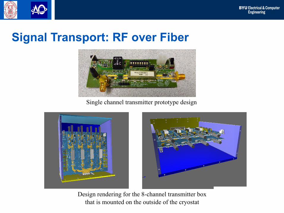
Signal Transport: RF over Fiber
Single channel transmitter prototype design
Design rendering for the 8-channel transmitter boxthat is mounted on the outside of the cryostat

Cornell'University.Ithaca&NY&14853,&USA&
To mass storageLustre File Storeand/or other back ends
(×10)
•••
4
4
•••
XilinxUltrascale+
RFSoCFPGA
(×9)
F Engine:Sampling, Polyphase filter bank and 100 Gbe I/O
4 x 25 GbE
SFP28
XB Engine:Correlator, Beamformer, Spectrometer
•••
(× 25)
From R
F over fiber downlink receivers
GPU server2U HPC (#1)
ZCU216 board (#1)
GPU server2U HPC (#25)
Ethernet Switch
64 port100 G
bE
RTX 2080 TI GPU
RTX 2080 TI GPU
RTX 2080 TI GPU
RTX 2080 TI GPU
16 on-chip2.5 G
spsAD
Cs
4 x 25 GbE
SFP28
ZCU216 board (#9)
16 on-chip2.5 G
spsAD
Cs
XilinxUltrascale+
RFSoCFPGA
(×9)
•••
(× 25)
•••
Beamformer Subsystems

Cornell'University.Ithaca&NY&14853,&USA&
• XZCU49DR RFSoC has 16 on-chip ADCs, 2.5 Gsamp/sec, with digital down conversion and lowpass filtering to complex baseband • Will directly sample RF over fiber downlinks with no
analog mixer• 4 x 25 GbE ports support I/O data rate to HPC/GPUs.• 9 of these ZCU216 boards will be used to support 138
antenna inputs• Oversampled polyphase filter bank for coarse frequency
channelization
RFSoC F-Engine

Cornell'University.Ithaca&NY&14853,&USA&
• Passband corners: 1300 MHz to 1720 MHz
• Band-defining filter attenuates adjacent RFI prior to the RF over fiber link to limit dynamic range
• Anti alias filter is just ahead of ADC to reduce noise aliased into passband
• Pre-ADC filter is lower order, lower cost
0 500 1000 1500 2000 2500 3000 3500Frequency, MHz
-60
-50
-40
-30
-20
-10
0
Mag
nitu
de fi
lter r
espo
nse,
dB
Analog Filter Responses
Pre-RFoF filterAliased pre-RFoFPre-ADC filterAliased pre-ADC Sample frequency: fs
ADC, Sampling, and Pre-Filtering

Cornell'University.Ithaca&NY&14853,&USA&
• Built-in ADC Digital Down Converter (DDC)
• 2 GHz sample frequency• Mixes sampled real RF down
to complex baseband• Decimates to final sample
rate of 500 MHz
ADC, Digital Down Conversion

Cornell'University.Ithaca&NY&14853,&USA&
• Built-in ADC pre-decimation anti-alias filter response.
• Decimation by 4 moves. 250 MHz to full bandwidth point at 1.0.
• Complex baseband sample rate is 500 MHz.
• 420 MHz usable passband. • No NCO tuning to select 305
MHz beamformer band: just pick from PFB channels.
• Ready for upgrade to 420 MHz beamformer with more HPCs.1000 MHz
Full bandwidth point for 2 Gsps sampling
210 MHz 250 MHz
Observed band center: 1510 MHz ←→ NCO frequency
ADC, Digital Down Conversion

Cornell'University.Ithaca&NY&14853,&USA&
Selected Coarse Channels
!b!k, j[n]xk[n] bk, j[n]
100
GbE
Sw
itch
Nvidia RTX 2080 Ti GPU, 1 of 2 per HPC
OversampledPFB channelizedpackets
Lustr
eDisk
Arra
y St
orag
e
FITS
For
mat
ter
4 X 25 GbE
Nvidia RTX 2080 Ti GPU, 2 of 2 per HPC
Cha
nnel
Sel
ectio
n (k
= ..
. )
Select up to half of thecoarse channels, in 44 MHz blocks
Single hashpipe instance per GPU
Fine PFB
Polyphasefilter bank
(128 point FFT)
Sk,( j, j )f
Fine Spectrometer Long-term Integrator
!S !k,( j, j )f =
1N
!b!k, j[n] !b!k, j* [n]
n=0
N−1
∑
!b!k, j[n]
Real-timeBeamformer
bk, j[n]=
wk, jH x k[n]
xk[n] bk, j[n]
100 ms min. integration dump time
Channel bonded25 GbE port pair
HI Mode, Fine PFB (1 of 25 HPCs)

Cornell'University.Ithaca&NY&14853,&USA&
Selected Coarse Channels
!b!k, j[n]xk[n] bk, j[n]
100
GbE
Sw
itch
Lustr
eD
isk A
rray
Stor
age
FITS
For
mat
ter
4 X 25 GbE
Real-timeBeamformer
bk, j[n]=
wk, jH x k[n]
xk[n]
Coarse Spectrometer Fast-dump Integrator
Sk,( j, j )c =
1N
bk, j[n]bk, j* [n]
n=0
N−1
∑
Sk,( j, j )cbk, j[n]
0.064 ms min. integration dump time
Nvidia RTX 2080 Ti GPU, 1 of 2 per HPC
Nvidia RTX 2080 Ti GPU, 2 of 2 per HPC
Cha
nnel
Sel
ectio
n (k
= ..
. )
Select up to all of thecoarse channels, in 44 MHz blocks
Single hashpipe instance per GPU
OversampledPFB channelizedpackets Channel bonded
25 GbE port pair
Transient Mode, Coarse PFB (1 of 25)
Cornell'University.Ithaca&NY&14853,&USA&
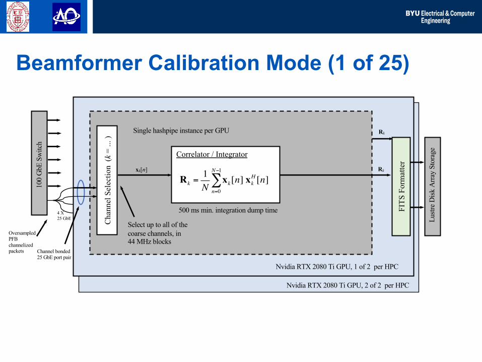
Selected Coarse Channels
!b!k, j[n]xk[n] bk, j[n]
100
GbE
Sw
itch
Lustr
eD
isk A
rray
Stor
age
FITS
For
mat
ter
4 X 25 GbE
xk[n]
Correlator / Integrator
Rk =1N
xk[n] xkH [n]
n=0
N−1
∑Rk
Rk
500 ms min. integration dump time
Nvidia RTX 2080 Ti GPU, 1 of 2 per HPC
Nvidia RTX 2080 Ti GPU, 2 of 2 per HPC
Cha
nnel
Sel
ectio
n (k
= ..
. )
Select up to all of thecoarse channels, in 44 MHz blocks
OversampledPFB channelizedpackets Channel bonded
25 GbE port pair
Single hashpipe instance per GPU
Beamformer Calibration Mode (1 of 25)