Design and construction of the 28 m tall self-supporting ...
14
Glass Struct. Eng. (2016) 1:233–246 DOI 10.1007/s40940-016-0027-0 CHALLENGING GLASS PAPER Design and construction of the 28 m tall self-supporting glass lift enclosure Gennady Vasilchenko-Malishev Received: 10 January 2016 / Accepted: 26 April 2016 / Published online: 10 May 2016 © Springer International Publishing Switzerland 2016 Abstract This paper describes the design, detailing and construction of an 8 storey high, 28 tall self- supporting lift enclosure for a residential property in Knightsbridge, London. The glass structure comprised of curved laminated glass cylinder of 1.4 m diameter with cantilevered steel staircase wrapping around it. The glass shaft is split at each floor level with helical steel handrail which also acts as a splice joint between top and bottom glass panels. Lift shaft terminates with static and openable semi-circle roof lights as well as cylindrical roof top structure, independently supported of cantilevered structure. When completed, in our opin- ion, the structure would be tallest self-supporting glass structure in the world. Keywords Curved glass · Vertically stacked glass · Tall glass structure 1 Historic precedents In our knowledge some of the first stacked load bearing glass walls started to be developed around late 1990s. One of the notable examples, from our G. Vasilchenko-Malishev (B ) Malishev Engineers Ltd, Bath, Somerset, UK e-mail: [email protected] point view, would be the Glass Cube Reading Room, Arab Urban Development Institute, Riyadh, Saudi Arabia, designed by Dewhurst Macfarlane and Part- ners (Macfarlane, Architectural Review Middle East 1999) . In this project, 3 rows of 2.67 m high façade panels are stacked (supported one on top of the other) rather than hung and are structurally bonded to the glass beams and columns to create a 8 m cube. We have used the above precedent to develop load bearing technology further in our Bolton’s Place res- idential development project in South West London using vertically stacked structural glass in three glass lift enclosures, completed in 2006. In this earlier project we have used vertically stacked triple laminated glass which carried it’s own weight five storeys up. Each shaft in this project measured 2.5 × 1.5 × 20 m high and comprised of laminated glass walls which were stacked on top of each other through a stain- less steel flat plate frame which provided lateral sta- bility through connection at each floor, see Figs. 1, 2, and 3. Based on our experience with the above project we were approached by the main contractor (Walter Lilly) who were working on a major refurbishment of the a residential property with a triple basement in Knights- bridge, London where the architects (Tim Flynn archi- tects, TFA) were designing a feature glass lift, Ø1.4 m and spiral staircase around it in a very confined floor space, connecting eight storeys with total height of around 28 m. 123
Transcript of Design and construction of the 28 m tall self-supporting ...

Glass Struct. Eng. (2016) 1:233–246DOI 10.1007/s40940-016-0027-0
CHALLENGING GLASS PAPER
Design and construction of the 28 m tall self-supportingglass lift enclosure
Gennady Vasilchenko-Malishev
Received: 10 January 2016 / Accepted: 26 April 2016 / Published online: 10 May 2016© Springer International Publishing Switzerland 2016
Abstract This paper describes the design, detailingand construction of an 8 storey high, 28 tall self-supporting lift enclosure for a residential property inKnightsbridge, London. The glass structure comprisedof curved laminated glass cylinder of 1.4 m diameterwith cantilevered steel staircase wrapping around it.The glass shaft is split at each floor level with helicalsteel handrail which also acts as a splice joint betweentop and bottom glass panels. Lift shaft terminates withstatic and openable semi-circle roof lights as well ascylindrical roof top structure, independently supportedof cantilevered structure.When completed, in our opin-ion, the structure would be tallest self-supporting glassstructure in the world.
Keywords Curved glass · Vertically stacked glass ·Tall glass structure
1 Historic precedents
In our knowledge some of the first stacked loadbearing glass walls started to be developed aroundlate 1990s. One of the notable examples, from our
G. Vasilchenko-Malishev (B)Malishev Engineers Ltd, Bath, Somerset, UKe-mail: [email protected]
point view, would be the Glass Cube Reading Room,Arab Urban Development Institute, Riyadh, SaudiArabia, designed by Dewhurst Macfarlane and Part-ners (Macfarlane, Architectural Review Middle East1999) . In this project, 3 rows of 2.67 m high façadepanels are stacked (supported one on top of theother) rather than hung and are structurally bondedto the glass beams and columns to create a 8 mcube.
We have used the above precedent to develop loadbearing technology further in our Bolton’s Place res-idential development project in South West Londonusing vertically stacked structural glass in three glasslift enclosures, completed in 2006. In this earlierproject we have used vertically stacked triple laminatedglass which carried it’s own weight five storeys up.Each shaft in this project measured 2.5× 1.5× 20 mhigh and comprised of laminated glass walls whichwere stacked on top of each other through a stain-less steel flat plate frame which provided lateral sta-bility through connection at each floor, see Figs. 1, 2,and 3.
Based on our experience with the above project wewere approached by the main contractor (Walter Lilly)who were working on a major refurbishment of the aresidential property with a triple basement in Knights-bridge, London where the architects (Tim Flynn archi-tects, TFA) were designing a feature glass lift, Ø1.4m and spiral staircase around it in a very confinedfloor space, connecting eight storeys with total heightof around 28 m.
123

234 G. Vasilchenko-Malishev
Fig. 1 Bolton’s place liftshafts, project completed in2006
Fig. 2 a General arrangement of the stainless steel structure b extract from a FE analysis
123

Design and construction of the 28 m tall glass lift 235
Fig. 3 Typical section through the glass
2 Design of the main shaft enclosure
2.1 Concept
From the early design meetings with the architects itwas clear that simple glass cladding supported at endof the cantilevered stair wasn’t desired by the TFA aswell as it would cause some issues with the differen-tials movement of the treads and necessity of providedcontinuous movement joint along the spiral edge. Ontop of all that, the architect liked the idea of having a“shadow gap” between the shaft and the edge of thestair. Which meant that the glass lift enclosure wouldhave to be structurally independent of the stair and carryit’s own weight all the way down to the foundations,see Fig. 4.
2.2 Design philosophy
The main shaft therefore was designed as an indepen-dent self-supporting structure with all the self-weightload supported at the bottom of the shaft on concreteslab. Helical steel handrails which split the glass at
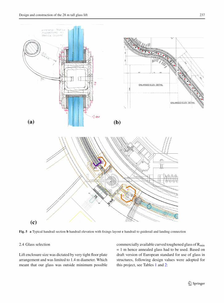
1m above each level of stair, wrapping around it, areacting as H-shaped channels transferring vertical loaddown from one panel to another, see Fig. 5a. Handrailsare fixed into vertical guide rail columns at each endwhich provides the stack its lateral stability, see Fig. 5c.Openable roof top (top hat or “the drum”)was designedas a structurally independent part relying on two can-tilevered beams rigidly fixed into ametal ring and outermain structure supporting the glass cylinder part, seeFigs. 4a and 6c.
2.3 Handrail design as a key to installation andreplacement strategy
One of the main difficulties in these kind of projects(confined tall spaces) is the installation of glass and it’sreplacement (in case if broken)—important criteria toconsider in the design. We have adopted simple stackfrom the bottom to the top approachwhich had implica-tions on the handrail design—one of the most compli-cated elements on the project. It has been decided thateach glass panel comes in pre-bonded channels (topand bottom only as vertical glass joints designed to be
123

236 G. Vasilchenko-Malishev
Fig. 4 a Typical floor plan of the lift shaft b roof light c axonometric general arrangement
open) and fitted into H-shaped handrail channel withseries of CSK screws, connecting outer plates of the Hprofile so that at later stage it can be simply unscrewedand panel taken out if replacement is required. As
a result elaborate system of metal plates with hit &miss cuts was developed to connect outer plates whichare fixing the glass channel to the handrail core, seeFig. 5.
123
Design and construction of the 28 m tall glass lift 237
Fig. 5 a Typical handrail section b handrail elevation with fixings layout c handrail to guiderail and landing connection
2.4 Glass selection
Lift enclosure size was dictated by very tight floor platearrangement and was limited to 1.4 m diameter. Whichmeant that our glass was outside minimum possible
commercially available curved toughened glass ofRmin
= 1 m hence annealed glass had to be used. Based ondraft version of European standard for use of glass instructures, following design values were adopted forthis project, see Tables 1 and 2:
123

238 G. Vasilchenko-Malishev
Fig. 6 a 3D design model view b max uls stress (2 MPa average, with maximum 5 MPa in some areas) c top hat “the drum” generalarrangement and deformation diagram with max SLS deformations around 2 mm
Table 1 Glass properties adopted, based on prEN13474,replaced by prEN16612
Glass type Designstrength(short term),MPa
Designstrength (longterm), MPa
Edgestrength(long term),MPa
Annealed glass 25 8.15 6.5
Toughened glass 79 70 56
Heat strengthened 40 29 23
Table 2 Other materials properties
Material Compressionstrength,MPa
Tensilestrength,MPa
Young’smodulus,MPa
Shearstrength,MPa
Stainlesssteel, S304
210 210 200,000 126
Arbokol682H grout
16.6 7.5 83 8.6
123

Design and construction of the 28 m tall glass lift 239
Table 3 Loadings adopted in the design based on BS EN 1991-1-1 (EC1 part 1) and UK NA
Load type CharacteristicUDL,kN/m2orkN/m
Characteristicpoint load, kN
Ultimate load,kPa or kN/m
Imposed load(live)
1.5 3 2.25
Imposed load(snow)
0.6 1.5 0.9
Handrail load 0.36 1 0.54
Glass panel thickness was adopted as 3× 8 mmannealed glass laminated with EVA interlayer each 1.5mm thick.
2.5 Other materials used in the construction
See Table 2.
2.6 Loading adopted in the design
See Table 3.
2.7 Load combinations used
Load combinations taken in accordance with Eurocode0 & 1:
ULS : 1.35Gk + 1.5Qk1 + 1.5Qk2
SLS : Gk + Qk1 + Qk2
2.8 Computer modelling
Full FE model was built in order to predict criticaldesign stresses and deformations under various designsituations. In total 13,905plates and862beamelementswere used with average FE element being 100× 100mm with denser mesh around the edges and corners,see Fig. 6. Openable roof top (top hat or “the drum”)was designed as a structurally independent part rely-ing on two cantilevered beams rigidly fixed into metalrings (inner and outer) which support the glass cylinderpart, see Fig. 6c. Therefore the main focus initially wasonto the analysis of the main lift shaft enclosure as itwas the heaviest part of the construction with longerprogram. Glass panels were modelled as solid platesof equivalent thickness, calculated in accordance with
Fig. 7 Extract from the glass schedule, developed surface, tender stage with maximum panel length 4.5 m
123

240 G. Vasilchenko-Malishev
Fig. 8 a Testingspecification sketch bsamples tested for adhesion,September 2015
procedures stipulated in the Institution of StructuralEngineers: Structural use of glass in buildings (2nd ed),(IStructE Feb. 2014) (Fig. 7).
2.9 Arbokol testing
Load transfer from glass to steel and back to lowerglass is largely depending on bearing through the groutas well as adhesion of grouting to glass and steel.Although general mechanical properties of the groutitself were known to us Arbokol datasheet supplied bythemanufacturer, adhesion between the grout and glass
was not, hence required testing. Testing was carried outin September 2015 by Sandberg. The test comprised ofthree samples of triple laminated glass 3× 8 mm thickin 40× 25 mm stainless steel channel, 100 mm long.Adhesion area was around 50mm long, with around15–20 mm embedment, see Fig. 8.
Test specimen were clamped in calibrated universaltest machine with load applied at the rate of 2 kN/min.Based on testing results and their evaluation designadhesion stress to the glass worked out to be around 2MPa, which is almost double of the stresses predictedin the FE model.
123

Design and construction of the 28 m tall glass lift 241
Fig. 9 Section through roof top cylinder glass (top hat)
Fig. 10 Section through bottom part of the openable roof top
3 Openable roof light
3.1 Design philosophy
The openable roof light (top hat) was designed to beindependent structurally from the rest of the glass lift
enclosure for various reasons. The ultimate top rooflight, circular in shape double glazed unit is designedto be removable for reasons of installation of glassand replacement if necessary. For glass compositionand typical section details through the “top hat” seeFig. 9.
123

242 G. Vasilchenko-Malishev
Fig. 11 a Handrail splicedetail b end of handrailbracket
Fig. 12 a Handrail splicedetail b end of handrailbracket
3.2 Rolling mechanism
Series of rollers were used on inner and outer perime-ter rings to support sliding roof light. The roof light,Ø3.4 m (outer) and Ø1.4 m (inner), comprised of cres-cent shape walk on double glazed units, with centralangle being 180◦ Top sheet of DGU, spanning 1mbetween inner and outer perimeter ring support, com-prised of 3× 10 mm toughened laminated glass andinner stepped sheet as 2× 6 mm thick toughened lam-inated glass, see Fig. 10.
The sliding unit is moving by means of spur pin-ion gear with planetary type motor with supporting V-shaped wheels spaced at 36◦, which equates at approx-imately 1m spacing on outer perimeter and 0.5 m spac-ing on inner perimeter.
4 Production
4.1 Handrail production
After about 1 year delay production has started withmanufacturing of the handrail, in June 2014 at GlassUK factory where steel drum was created to be used asa template for the curvature, see Fig. 11.
4.2 Glass production
Due to various commercial considerations the glasssub-contractor chose to produce all the curved glassin the UK at their factory. A lot of sacrificial slump-ing test panels were created until visual qualities andappearance of the panel satisfied specification. Addi-tional difficulties occurred due to rhomboid shape of
123

Design and construction of the 28 m tall glass lift 243
Fig. 13 a 1 m by 1 mSpecimen b trial applicationc different grade arbokol dfinal inspection andapproved grade
the glass and special procedures were required to createrequired curvature, see Fig. 12. When the glass slump-ing was resolved lamination was carried out using EVAfilm of 1.5 mm thick.
4.3 Arbokol workability test
Glass production tolerances adopted based on “Glazingmanual” by GGF (glass and glazing federation)
(i) Maximum step onlong edge, mm
1 overall, 2 mm maxstep on the edge
(ii) Maximum step onshort edge (T&B), mm
1.5 overall, 3 mm maxstep on the edge
(iii) Overall thickness,mm
2.3
(iv) Girth variation, mm 2(v) Vertical edgestraightness (warp),mm/m
1 Total 4 mm
(vi) Vertical edge sidestraightness, mm/m
1.25 Total 5 mm
123

244 G. Vasilchenko-Malishev
Fig. 14 a Crane lift to theroof b through oculus cdown in the shaft dinstallation of the openableroof light
5 Construction
5.1 Installation of glass
Installation of glass began aroundMarch 2015 and tookalmost exactly one year to complete. Glass was liftedupwith hoists using overhead gantry and down through
the oculus of the openable roof light. Despite very tightworking space none of the glass panels were damagedduring installation process. Hydraulic ram lift was usedas a working platform to facilitate the process of instal-lation. Slow speed of installation ensured that groutingwas properly cured before the next level of glass isreceived (Figs. 13, 14, 15).
123

Design and construction of the 28 m tall glass lift 245
Fig. 15 View of thesegment, across and top hat.View up completed shaft
6 Conclusion
In conclusion, after a long period of design, manufac-turing and construction, 28 m tall lift shaft was com-
pleted on the 29th March 2016, making this structure,in our view, tallest self-supporting glass structure in theworld (Vasilchenko-Malishev 2016), and further push-ing boundaries of edge bearing technology in glass.
123
246 G. Vasilchenko-Malishev
Acknowledgments Tim Flynn Architects, Walter Lilly (maincontractor), Glass UK (glass supply and install).
References
AdsheadRatcliffe&CoLtd:Arbokol 682data sheet. http://www.arbo.co.uk/arbo-sealants/arbokol-682-balustrade-sealant/(2017)
Institution of Structural Engineers: Structural Use of Glass inBuildings, 1st edn. IStructE, London (1999)
Institution of Structural Engineers: Structural Use of Glass inBuildings, 2nd ed. IStructE, London (2014)
Macfarlane, T.: ConstructionDetails for Structural Glass Assem-blies. Glass Processing Days, pp. 474–476 Tampere (1999)
Macfarlane, T.: Glass distinction, pp. 34-36, The ArchitecturalReview Middle East (1999)
prEN13474.: Glass in building-determination of the load resis-tance of glass panes, replaced by prEN16612 (2013)
Vasilchenko-Malishev, G.: Sustainable Design in Glass. Innova-tive Glazing Global Summit, Berlin (2016)
123