DESIGN AND CONSTRUCTION OF HOT BLAST STOVE …library.aimehq.org/library/books/Ironmaking...
12
DESIGN AND CONSTRUCTION OF HOT BLAST STOVE PLANTS FOR HIGH BLAST TEMPERATURES AND HIGH BLAST PRESSURES Helmut Palz and Arthur Heuer Didier-Werke AG Wiesbaden, West Germany Why High Blast Temperatures and High Blast Pressures for Modern Blast Furnaces? Because of the ever increasing price of coke, it has been of interest for steel industries of Europe and Japan especially, to utilize cheap heavy oil for blast furnace operation in place of coke. In order to achieve high injection rate of these cheap oils, it was found that higher hot blast temperatures would be required. Along with this development, and others noted below, not only has a savings in coke been realized in the operations of the furnace, but their specific production rates have I~ been increased. These improvements have been realized as a result of the following developments: 1. Increase in the hot blast temperature to 2500'~ and above. 2. Improvement of the ore fluxes; such as the use of sinter, lump ore with controlled grain sizes, pellets, iron concentrations in ore, prereduced material, etc. 3. Operation of back-pressure furnaces to 45 psig top pressure. 4. Concentration of the hot blast to approximately 27% oxygen content. 5. Injection of reducing gases into the blast furnace stack. With these improvements (increase of hot blast temperature, oxygen concentration of the blast, improvenents of the ore and flux preparation'^ and improvement in furnaces, control of the furnaces through computers as well as the injection of water-oil emulsions) it has become possible to increase the oil charge without soot being deposited in the gas cleaning system. For example, in Germany from 1960 to 1971, the average coke consump- tion was reduced from 1540 lbs to 1100 lbs per ton of pig iron produced. The injection rate of oil now found most favorable is approximately 260 lbs of oil and 850 lbs of coke per ton of pig iron produc~zd. Fig. lI shows this developing trend in Europe. The calorific value of the blast furnace gas fell tcu app-roximately 80 btulscf due to the injection rate of small amounts of oil. This < value has been increased because of the use of higher hot blast temp- 11 eratures in connection with the injection of larger quantities of oil, (this is, 260 lbs per ton of pig iron with the gas content now up to 90 btulscf.) It is to be expected that with oxygen concentration in the blast, a calorific value of approximately 110 btu/scf will be achieved.
Transcript of DESIGN AND CONSTRUCTION OF HOT BLAST STOVE …library.aimehq.org/library/books/Ironmaking...

DESIGN AND CONSTRUCTION OF HOT BLAST STOVE PLANTS
FOR HIGH BLAST TEMPERATURES AND HIGH BLAST PRESSURES
Helmut Palz and Arthur Heuer
Didier-Werke AG
Wiesbaden, West Germany
Why High Blast Temperatures and High Blast Pressures for Modern Blast Furnaces?
Because of the ever increasing price of coke, it has been of interest for steel industries of Europe and Japan especially, to utilize cheap heavy oil for blast furnace operation in place of coke. In order to achieve high injection rate of these cheap oils, it was found that higher hot blast temperatures would be required. Along with this development, and others noted below, not only has a savings in coke been realized in the operations of the furnace, but their specific production rates have
I~ been increased. These improvements have been realized as a result of the following developments:
1. Increase in the hot blast temperature to 2500'~ and above. 2. Improvement of the ore fluxes; such as the use of sinter, lump
ore with controlled grain sizes, pellets, iron concentrations in ore, prereduced material, etc.
3. Operation of back-pressure furnaces to 45 psig top pressure. 4. Concentration of the hot blast to approximately 27% oxygen
content. 5. Injection of reducing gases into the blast furnace stack. With these improvements (increase of hot blast temperature, oxygen
concentration of the blast, improvenents of the ore and flux preparation'^ and improvement in furnaces, control of the furnaces through computers as well as the injection of water-oil emulsions) it has become possible to increase the oil charge without soot being deposited in the gas cleaning system.
For example, in Germany from 1960 to 1971, the average coke consump- tion was reduced from 1540 lbs to 1100 lbs per ton of pig iron produced. The injection rate of oil now found most favorable is approximately 260 lbs of oil and 850 lbs of coke per ton of pig iron produc~zd. Fig. lI shows this developing trend in Europe.
The calorific value of the blast furnace gas fell tcu app-roximately 80 btulscf due to the injection rate of small amounts of oil. This <
value has been increased because of the use of higher hot blast temp- 11
eratures in connection with the injection of larger quantities of oil, (this is, 260 lbs per ton of pig iron with the gas content now up to 90 btulscf.) It is to be expected that with oxygen concentration in the blast, a calorific value of approximately 110 btu/scf will be achieved.

An interesting approach toward the development of higher hot blast temperatures has been attained with the use of blast furnace gas only. This very economical method of operation is achieved with the pre-heating of combustion air. In this particular case there were extra idle stoves available which were utilized to preheat combustion air. These stoves were fired by blast furnace gas. The preheated combustion air was then used in the new stoves which were also fired only by blast furnace gas and resulted in the achievement of a straight line hot blast temperature of 2300°F in 1969.
Hot Blast Stoves for Modern Blast Furnaces
The development of the blast furnace operation as described above requires a completely new approach for the production of high hot blast temperatures and pressures. In fact, these developments could not have been possible without such blast temperatures and pressures.
In the case of new blast furnace construction, particularly, the larger hearth diameter furnaces, these hot blast temperatures and press- ures have been reached almost exclusively through the use of external combustion chamber stoves. However, there are many existing stoves throughout the world which are of the conventional internal combustion chamber type. These stoves represent a large captial investment and it would be difficult if not impossible to replace them in the very near future. Therefore, a design had to be developed to enable this older type of stove to be upgraded to a point where it could produce the hot blast temperatures required. This often also required the use of greater hot blast volumes and a consequent reduction in blast time.
Didier was the first company to begin upgrading existing stoves to achieve these high hot blast temperatures. Originally, six internal combustion chamber stoves for hot blast temperatures to 2300'~ were modified with great success. This upgrading utilizes the existing shell, a major portion of the checker work and lining and requires only the replacement of the upper portions of the checker work with high effic- iency checker brick. The combustion chamber must also be rebuilt through the use of silica refractories and high efficiency ceramic burners. The problem of major importance in such upgrading has been the sealing between the combustion chamber and the checker chamber. This solution depends primarily on the special construction of the breastwall using silica refractories.
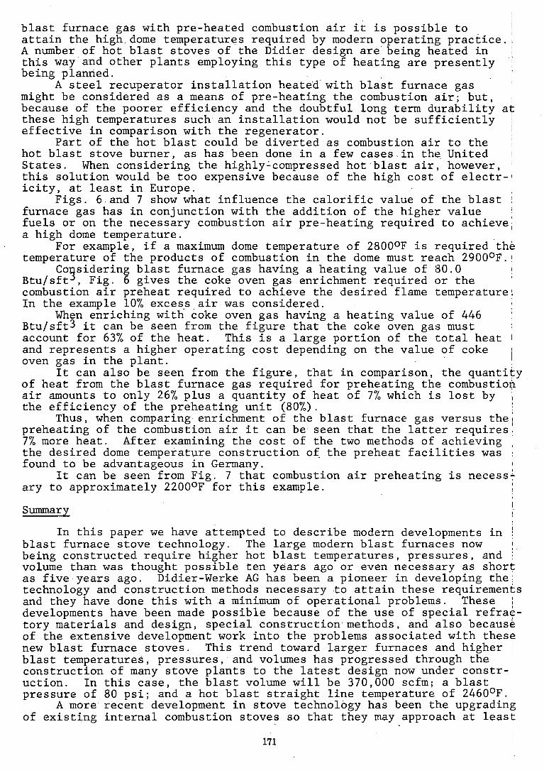
In the case of new green field installations, where new stoves and a new blast furnace plant are to be installed, the most modern design now in use is that of the external combustion chamber stoves. Such stove designs are shown in Fig. 2.
The original design of the external combustion chanber stove was developed by Didier-Werke, and since its inception, continuous development has taken place to the point where a very high percentage of the larger stoves being built in the world today are built by Didier-Werke as external combustion chamber units. One of the main advantages of this stove construction over the internal combustion chamber type has to do with temperature differences existing between the combustion chamber and the checker chamber. In the case of the normally designed internal combustion chamber stove the hottest part of the combustion chamber is in close proximity to the coldest part of the checker work. In external combustion chamber stoves there is no connection between the two chambers and, the entire external combustion chamber shell is exposed to the same outside temperature. The distribution of heat within this combustion chamber is completely uniform throughout its shape and therefore, expansions are uniform and can be calculated to a close tolerance.
The installation of the first external combustion chamber stoves were watched with great interest. Since then, the trouble-free start up

and the faultless operation has been observed by blast furnace engineers and many such stoves have been installed. The primary difference in these three designs as shown in Fig. 2, is in the connection between the two chambers. A brief description of the different designs is as follows:
Year First System Shape of Dome Stove Built Company
11
Martin & Horizontal tube-type dome 1965 ATH Pagenstecher with equal quarter-cone
shaped ends.
Koppers Two hemispherical domes with tube connection.
1963 Salzgitter
Didier Diffusor shaped common dome. 1959 Rochling
The differnt shapes of the domes necessitate different heights of stoves and different distances between combustion chambers and checker chambers for the same capacity.
External Combustion Chamber Stove, Didier Design
The first problem to be solved in the construction of an external combustion chamber stove is the connection of the two chambers. This connection should-not only ensure a smooth transfer of the coxbustion gas into the checker chamber and of the hot blast into the combustion chanber, but it also must be of such a shape that a long refractory life would be assured. The solution in our case was the use of a common dome which covered both chambers (Fig. 3). The common dome exceeds the diameter of both chambers by the width of a box girder which is located just under the dome and encircles both shafts or chambers.
Refractorv Materials for High Tem~erature Stoves
The maximum temperatures which determine the requirements of refractory quality in hot blast stoves are found in the combustion chamber, the dome and the upper part of the checker work. The key parameter is the temperature attained in the dome. It is assumed that the same temperature exists in the combustion chamber during the entire heating period and also in the upper part of the checker work and checker chamber at the end of the heating period. These temperatures determine the quality and thick- ness of the refractory lining as well as the quality, thickness, and number of insulating layers. Other factors have also been taken into 11
account, such as the stresses arising from the weight of the refractory lining, stress arising from the thermal expansion, and also any temper- ature fluctuations that may occur. Based on experience gained so far, the following lining systems are used in Europe:
Refractory Lining for the Hot Areas ~ i n i m m Oualityua'lity
40-42% A1203
43% A1203
Mullite
Silica
43% A1203
Silica
Silica
Silica

It may be suprising to note that Silica has been proposed for a dome temperature of only 25000F; however, there is no other material that is suitable for such a wide range of application. The reason for this is that the hot strength of Silica begins to decrease only as the melting
' point is approached. A further consideration is that top quality Silica brick can be manufactured at a lower price than Mullite brick.
Brick qualities for installation in hot blast stoves are selected considering the stresses to which they are subjected in operation, that is, the simultaneousapplication of high temperature and load. Above all, the creep behavior is of the utmost importance. As hot blast stoves are built for long life, it is essential to know how the properties of the bricks change during long periods of time. To simulate these conditions, new test methods had to be developed which furnished information on the refractory behavior under the simultaneous effect of temperature, load, and time.
Each refractory material has its own particular limitations which, when exceeded, cause failure of the material. Within the different groups of materials good creep behavior can be expected if the following requirements are met:
1. Low content of fluxes. 2. High density due to optimum grading of grain sizes and the
application of high pressure in the molding process. 3. Sufficiently high firing temperature and long firing time.
High Efficiency Checker Work, Didier Design
The size and cost of a hot blast 'tove depends to a large extent on the volume of the checker work required. In this connection, attention must be given to the following points:
1. The shape and the wall thickness of the checker bricks must be designed in such a way that they can be manufactured economically and with a high degree of operational safety to insure the long life of the stove.
2. The wall thickness on the checker brick must be determined considering the desired blast time.
3. The shape of the flues and their hydraulic diameter as well as the free cross sectional area of the checker work must be designed so that the pressure loss is kept within acceptable limits.
Based on these requirements, the Didier design checker work has been developed. The minimum wall thickness of Silica and high alumina refrac- tories is 1.0 in. average, and for fireclay bricks 0.8 in. The hexagonal cross section of the flue was preferred to other shapes because it offers the most favorable wall thickness and also has the smallest dead area between the flues. (That is, the area that does not participate in the heat exchange). The hydraulic diameter of the flues in the upper part of the checker work (the approximately 215 of the total height in the Silica, high alumina, and super duty fireclay zones) was fixed at 1.2 in. This results in a pitch, or distance between all flue axes of 2.2 in.
This pitch is used throughout the entire checker work. In the lower part of the checker work, in which checker bricks of fireclay are used, the wall thickness is reduced to 0.8 in. average. Therefore, the diameter of the channel is increased to 1.4 in. The effect of this is that the brick mass per unit of volume is reduced and the heating surface is increased.
The reduction in weight and the increase in heating surface is in accordance with the lower heat conductivity of fireclay brick in this temperature range as com,~~~edto the higher heat conductivity of Mullite, super duty fireclay, and above all, silica in the high temperature range in the upper part of the checker work. The reduction in heat transfer

by radiation in the lower temperature region is compensated to some extent by the increase of the flue diameter. The special feature of the Didier design checker work is that all flues in the checker bricks are tapered. This applies not only to the flues in the brick, but also to the partial flues around the outside of the brick. This is the 112 or 1/,3 flues that are molded into the perimeter of the checker brick and which form complete flues when the checker bricks are mated. The taper of the flue is 0.16 in. resulting in the diameter of the channels at one end of the brick being 0.16 in. larger than at the other. The resulting reduction in cross section is approximately 30% between the two ends of the brick. The velocity of the heating gas or the hot blast flowing through the checkerwork flues is changed accordingly. This change in velocity increases the flow turbulence along the flue wall, thus improving the heat transfer. A section of the Didier checker is shown in Fig. 4.
The checker work is installed in a bonded system so that each checker brick spans three ehecker bricks of the course underneath. The holes (flues) in the checker brick are aligned vertically one on top of the other. Each checker has three recessed flues on the bottom and three projecting flues on top so that when installed the locking tongue and grooveeffect prevents successive courses from displacing laterally. Prior to installation, all checker bricks are sorted into groups according to the variance in the height of the bricks. Within each group, a tolerance of +0.02 in. is allowed. Each group is marked with a specific color and only bricks of the same group are used in each layer. Normally, all checker bricks fit into one of three groups. This system ensures a very stable checkerwork (see Fig. 5 which shows checkerwork which has been in service for three years). The twisting and lateral dispacement that has been observed when the checker bricks are installed in columns is prevented by the Didier system. The checkerwork of various stoves installed in this manner has been investigated after more than ten years continuous operation and it was found that the flues were still absolutely vertical. Only a thin dust layer in the uppermost brick course disting- uished these bricks from new ones.
The checker brick installed along the outside of the checker work are formed in such a way that a gap is left between the wall lining and the checkerwork. The gap is big enough to take up the horizontal thermal expansion of the checkerwork. The top part of the checkerwork is stepped as shown in Figs. 3 and 5. This makes use of the available space in the,, dome, produces a more uniform flow of the gases and allows a reduction of the total stove height.
Corrosion Protection
Over a period of operation, damage to the steel shell in the area of the dome has been observed in some stove designs. The cause was thought to be inter-crystalline stress corrosion. This damage was observed on high temperature stoves which did not have a common dome for both shafts and no expansion joint for the combustion chamber. In the one case it was thought that the corrosion was caused by moisture condensation together with the formation of calcium nitrate which was formed by oxid- ation of nitrogen and its reaction with a calcium containing component of the insulation. In the other case, traces of sulfur and chlorine were found and it was thought that these started the stress corrosion.
After a nitrate coating was discovered on the inner surface of a stove's steel shells, an'investigation was performed and the formation of NO and NO2 was measured in a blast temperature range between 2300'~ and 2500°F. The investigation indicated that between 40 and 600 ppm NO and NO2 occurs depending on temperature, pressure, and time of the hot blast in the stove (100 ppm = 0.01% by volume or approximately 0.2 grams). It is assumed that the dew point is approximately 280'~ in connection with the acids that are produced by the formation of NO.

Apart from this the possibility of the formation of salts exists. Protection of the inside of the steel shell can be accomplished by insul- ating the outside of the shell to prevent the dew point from being reached inside. However, nitrates have a relatively low melting point (approx- imately 500°F) and maintaining too high a temperature inside will produce a form of corrosion due to the melting salt. Since NO only converts to nitric acid by the influence of oxygen and water according to the follow- ing equation:
2 NO + H20 + 1.5 O2 -> 2 HN03
and the corresponding conditions of equilibrium. It is to be expected that this acid plays a considerable role in the corrosion.
Attack by corrosive liquids and salts are not the only causes of corrosion. For corrosion to occur the following conditions must exist:
1. Stress concentrations occur in the steel shell dependent on the type of construction, internal pressure and differences in temperature. The crystalline structure of the steel is thereby weakened at the grain edges, whereby it is possible during the course of time for the corrosive liquids to penetrate into the steel structure. Designs which are free of stress concentrations are therefore considerably less susceptible.
2. When the temperature is below the dew point water is formed. This water reacts in connection with NO2, SO2, and 02 to form acids.
3. Salts such as calcium nitrate, Ca (NO ) 2 , and ammonium nitrate, (NH4) Hog, are formed and in their mo 1 ten state are corrosive.
Experience wlth this form of structural attack led to the use of special corrosion resistant steels for the dome and to the application of insulation on the outside of the shell in the upper part of the stoves. The purpose of the insulation is to keep the temperature in the shell above the dew point of the solution containing the corrosive agents so that condensation is prevented.
High temperature hot blast stoves of the Didier design have not yet shown signs of inter-crystalline stress corrosion. The corrosion pro- tection provided by glueing the outer layer of insulation onto the shell may be responsible for this. - The reason may, however, be that there is relatively little concentration of stress in the dome because of the efficiency of the expansion joint in the combustion chamber shell. As a further precaution, however, effective corrosion protection has been developed by Didier and is being used in hot blast stove construction. This construction is as follows: After the first layer of sufficiently rigid insulation block has been attached to the complete inside of the shell using adhesive, sheets of dimpled aluminum foil (to give strength and flexibility) are attached (also by adhesive) to the insulation blocks. The foil sheets are overlapped thus sealing themselves and in effect forming a complete aluminum shell vapor barrier within the stove shell by insulation block. On top of this aluminum sheathing is attached the soft insulation felt. The normal construction of the lining now commences Sandwiched between the insulating materials is a gas tight aluminum inner shell which is at a temperature higher than the dew point of the gases. Because of this construction the gases cannot reach the steel shell.
Heating with Only Blast Furnace Gas and Preheated~Combus tion Air
Often there are not other consumers for the low calorific blast furnace gas than the blast furnace plant itself. Therefore, it is logical to use the maximum amount of blast furnace gas in the blast furnace plant for,the production of the hot blast. By burning only blast furnace gas with pre-heated combustion air, or by burning pre-heated
blast furnace gas with pre-heated combustion air it is possible to 11
attain the high dome temperatures required by modern operating practice.: A number of hot blast stoves of the Didier design are being heated in this way and other plants employing this type of heating are presently being planned.
A steel recuperator installation heated with blast furnace gas might be considered as a means of pre-heating the combustion air; but, because of the poorer efficiency and the doubtful long term durability at these high temperatures such an installation would not be sufficiently effective in comparison with the regenerator. '1
Part of the hot blast could be diverted as combustion air to the ~ hot blast stove burner, as has been done in a few cases in the United 11
States. When considering the highly'compressed hot blast air, however, this solution would be too expensive because of the high cost of electr-I icity, at least in Europe.
Figs. 6 and 7 show what influence the calorific value of the blast furnace gas has in conjunction with the addition of the higher value fuels or on the necessary combustion air pre-heating required to achieve; a high dome temperature.
For example, if a maximum dome temperature of 28000F is required the temperature of the products of combustion in the dome must reach 290O0F.1l
Co sidering blast furnace gas having a heating value of 80.0 3 1
Btu/sft , Fig. 6 gives the coke oven gas enrichment required or the I
combustion air preheat required to achieve the desired flame temperature. In the example 10% exces-s air was considered.
When enriching with coke oven gas having a heating value of 446 ~tu/sft3 it can be seen from the figure that the coke oven gas must account for 63% of the heat. This is a large portion of the total heat 1
and represents a higher operating cost depending on the value of coke oven gas in the plant. 1
It can also be seen from the figure, that in comparison, the quantity of heat from the blast furnace gas required for preheating the combustion air amounts to only 26% plus a quantity of heat of 7% which is lost by the efficiency of the preheating unit (80%).
Thus, when comparing enrichment of the blast furnace gas versus the^ preheating of the combustion air it can be seen that the latter requires 7% more heat. After examining the cost of the two methods of achieving the desired dome temperature construction of the preheat facilities was found to be advantageous in Germany. I
It can be seen from Fig. 7 that combustion air preheating is necessi ary to approximately 2200°F for this example.
Summary
In this paper we have attempted to describe modern developments in ( blast furnace stove technology. The large modern blast furnaces now I
being constructed require higher hot blast temperatures, pressures, and volume than was thought possible ten years ago or even necessary as short as five years ago. Didier-Werke AG has been a pioneer in developing the technology and construction methods necessary to attain these requirements and they have done this with a minimum of operational problems. These ll
developments have been made possible because of the use of special refrac- tory materials and design, special construction methods, and also because of the extensive development work into the problems associated with these new blast furnace stoves. This trend toward larger furnaces and higher ~ blast temperatures, pressures, and volumes has progressed through the construction of many stove plants to the latest design nolw under constr-I uction. In this case, the blast volume will be 370,000 scfm; a blast pressure of 80 psi; and a hot blast straight line temperature of 2460°F.
A more recent development in stove technology has been the upgrading of existing internal combustion stoves so that they may approach at least

some of the parameters noted above for the modern external combustion stoves. By utilizing the existing shells, a major portion of the exist- ing checker work, and changing only the combustion chamber, burner, and dome, and a portion of the checkers, these stoves have been upgraded to a point where they are able to obtain hot blast temperatures of 2460'~.
A development of primary importance in the process is that of the ceramic burner. It is felt that the rates being attained today would not 6e possible with metallic burners. Also, of great importance has been the developments in the design and construction techniques of the hot blast mains, bustle pipe, mixer boxes, and tuyeres. This was found necessary to move the hot blast form the stoves to the furnace.
Because of these dramatic increases in volumes, temperatures, and pressures, it became necessary to redesign some of the auxiliaries to blast furnace stove plants. In particular, a major problem was encount- ered with valving, and because of this, the Didier group acquired the Hermann Rappold Company in 1957. Through them have developed valves 'required to handle these temperatures, pressures, and volumes. Such valves are now found in all of the major steel plants in the world.
Fig. 1. Development of the Oil and Coke Consumption for the Blast Furnace Process in Europe.
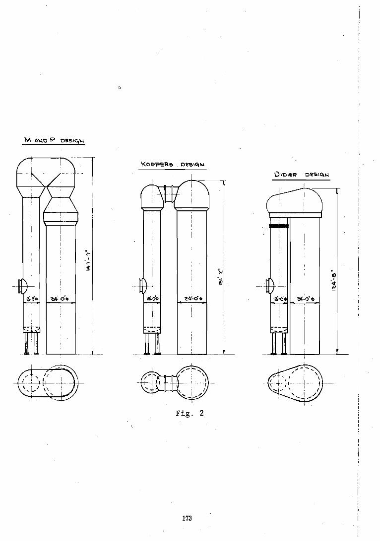
Fig. 2

i... . .. - .. ... .. .: . .. . . . . . .. . . .. . . .. .- . . . . _ . . . . . . .. . . . . ... J
Fig. 3. External Combustion Chamber. Dome.
Fig. 4.
No. bricks sq. yd. No. bricks cu. yd. Avg. free cross
section. area Weight per brick Weight per cu. yd.
GS 2/55 Fire clay Brick
GS 3/55 Silica Brick
~eaEina- surf ace- 'per &. yd. 380 sf 327 sf
dh hydraulic diam. 1.37" 1.18" X heating surface
thickness 0.5" 0.7" K in millimeters 33/37 28/32 W -in millimeters 22/18 27/23

Fig. 5. Didier Checkerwork Construction.
04. V W. HERT INPUT FROM PREMEATED COMB. AIQ -- QTOTAL TOTAL UFAT \NPUT lUTO STOVE
F i g . 6
175
TE \A P E RATURB OF THE PREHEATED COMBUST\OU A14 \U RELAT\O N TO THE FORT\OU Of HEW \NPUT FROU THE PREHEATED A\9 WWCH IS NECESSARY TO A-l-TAIN TH': T H E 0 4 E T \ C A L ' COMBUST\OU TEMPERATURE FoR D\FFEREUT Q U A U I \ T \ E S OF EXCESS A\4 <A)
. .
THE PORT\ONS OF HEAT INPUT \u RELATION TO THE T H E O R . COMB, TEMPERATURE, SEE F~GuRE 6 ///
0.0 ! I I I I I I I I I I
0 I
200 400 600 750 930 1113Q 1300 L4SO YbSO 1800 2000 Z<OO
~ M P E R A T u R E OF COMBUSTIOU A\R OF
Fig. 7