Design and Analysis of Multi-Section Variable Camber · PDF fileDesign and Analysis of...
7
ISSN (Print): 2321-5747, Volume-1, Issue-1, 2013 122 Design and Analysis of Multi-Section Variable Camber Wing Anita Nadar, Rizwan Khan, Parag Jagnade, Preshit Limje, Nishant Bhusari & Kushal Singh AE Department, PCE, RTM Nagpur University, Nagpur E-mail : [email protected], [email protected], [email protected] [email protected], [email protected], [email protected] Abstract – Minimizing fuel consumption is one of the major concerns in the aviation industry. In the past decade, there have been many attempts to improve the fuel efficiency of aircraft. One of the methods proposed is to vary the lift-to- drag ratio of the aircraft indifferent flight conditions. To achieve this, the wing of the airplane must be able to change its configuration during flight, corresponding to different flight regimes. Conventionally high lift devices like Flaps are used for this purpose but there functioning system is quite costly, heavy and noisy. In this project the aerodynamic characteristics of a multi-section, variable camber wing will be investigated. The model to be used in this project will have a 19.7cm chord and a 20cm wingspan, with the ribs divided into 3 sections such that section will be made to rotate approximately 1 degree without causing significant discontinuity on the wing surface manually. The multi- section variable camber wing model is expected to provide up to 10 per cent change in camber from the baseline configuration. Keywords – Multi Section, Variable Camber wing, Rigid wing, Flaps, Wingspan, Ribs. I. INTRODUCTION A small percentage reduction in the fuel consumption of an airplane can lead to major savings in aircraft operational costs. Since the amount of fuel stored in the aircraft is limited, lower fuel consumption means greater range or endurance in flight. There has been a great deal of research focused on achieving this goal. One promising concept is the use of a variable camber wing. This wing can change its configuration and provide variations in lift and drag that satisfy different flight conditions so fuel can be consumed efficiently. Variable camber wing concepts have been explored and developed extensively since the beginning of flight. The wing warping of the Wright Flyer, which used the pulling of cables to change the configuration of the wing tips was considered the first variable camber wing concept. The most significant variable camber devices currently used in most transport aircrafts are high-lift devices such as leading-edge slats and trailing-edge flaps. Those devices have demonstrated very promising results in reducing fuel consumption. Throughout this thesis, a wing with high-lift devices will be referred to as a conventional variable camber wing. Even though traditional high-lift devices have shown the capability of improving the aerodynamic performance of the aircraft, these systems involve discontinuities or sudden curvature changes in the aerofoil cross-section and also involve complex and bulky actuation systems. Thus, the variable camber wing concept that can improve aerodynamics properties of the plane in different flight conditions and at the same time be simple and lightweight must be investigated. This research focuses on designing and testing a variable camber wing model using multi section ribs. The model consists of four sets of three NACA 0015 aerofoil rib-sections connected through sub-spars; each section of the rib can rotate up to 5 degrees upwards or downwards without causing major discontinuity on the aerofoil cross-section. Fig. 1 : Multi-Section Variable Camber Wing
Transcript of Design and Analysis of Multi-Section Variable Camber · PDF fileDesign and Analysis of...

ISSN (Print): 2321-5747, Volume-1, Issue-1, 2013
122
Design and Analysis of Multi-Section Variable Camber Wing
Anita Nadar, Rizwan Khan, Parag Jagnade, Preshit Limje, Nishant Bhusari & Kushal Singh
AE Department, PCE, RTM Nagpur University, Nagpur
E-mail : [email protected], [email protected], [email protected]
[email protected], [email protected], [email protected]
Abstract – Minimizing fuel consumption is one of the major
concerns in the aviation industry. In the past decade, there
have been many attempts to improve the fuel efficiency of
aircraft. One of the methods proposed is to vary the lift-to-
drag ratio of the aircraft indifferent flight conditions. To
achieve this, the wing of the airplane must be able to change
its configuration during flight, corresponding to different
flight regimes. Conventionally high lift devices like Flaps are
used for this purpose but there functioning system is quite
costly, heavy and noisy. In this project the aerodynamic
characteristics of a multi-section, variable camber wing will
be investigated. The model to be used in this project will have
a 19.7cm chord and a 20cm wingspan, with the ribs divided
into 3 sections such that section will be made to rotate
approximately 1 degree without causing significant
discontinuity on the wing surface manually. The multi-
section variable camber wing model is expected to provide up
to 10 per cent change in camber from the baseline
configuration.
Keywords – Multi Section, Variable Camber wing, Rigid
wing, Flaps, Wingspan, Ribs.
I. INTRODUCTION
A small percentage reduction in the fuel
consumption of an airplane can lead to major savings in
aircraft operational costs. Since the amount of fuel
stored in the aircraft is limited, lower fuel consumption
means greater range or endurance in flight. There has
been a great deal of research focused on achieving this
goal. One promising concept is the use of a variable
camber wing. This wing can change its configuration
and provide variations in lift and drag that satisfy
different flight conditions so fuel can be consumed
efficiently.
Variable camber wing concepts have been explored
and developed extensively since the beginning of flight.
The wing warping of the Wright Flyer, which used the
pulling of cables to change the configuration of the wing
tips was considered the first variable camber wing
concept. The most significant variable camber devices
currently used in most transport aircrafts are high-lift
devices such as leading-edge slats and trailing-edge
flaps. Those devices have demonstrated very promising
results in reducing fuel consumption. Throughout this
thesis, a wing with high-lift devices will be referred to
as a conventional variable camber wing.
Even though traditional high-lift devices have
shown the capability of improving the aerodynamic
performance of the aircraft, these systems involve
discontinuities or sudden curvature changes in the
aerofoil cross-section and also involve complex and
bulky actuation systems. Thus, the variable camber wing
concept that can improve aerodynamics properties of the
plane in different flight conditions and at the same time
be simple and lightweight must be investigated.
This research focuses on designing and testing a
variable camber wing model using multi section ribs.
The model consists of four sets of three NACA 0015
aerofoil rib-sections connected through sub-spars; each
section of the rib can rotate up to 5 degrees upwards or
downwards without causing major discontinuity on the
aerofoil cross-section.
Fig. 1 : Multi-Section Variable Camber Wing
International Journal on Mechanical Engineering and Robotics (IJMER)
ISSN (Print): 2321-5747, Volume-1, Issue-1, 2013
123
The skin of the wing is made of the insignia cloth (an
adhesive backed polyester fabric for making banners
and flags) and silicon rubber sheet bonded together.
Both materials provide sufficient strength and elasticity
for the wing in both baseline and morphing
configuration. Figure 1 shows the multi-section variable
camber wing used for wind tunnel testing.
II. VARIABLE CAMBER WING DESIGN
Three wind tunnel models were constructed for this
research: one multi-section variable camber wing and
two rigid wings of the baseline (Symmetrical)
configuration and of the cambered configuration of the
variable camber wing. Detailed information of these
wing models are described as follows.
The initial inspiration of this wing concept began
with the desire to change the camber of the wing by
deflecting only the leading edge and trailing edge
portion of the wing without having any gap between
each portion. Using a three-section wing concept, the
provided a smooth change during cambered
configuration. Dividing the wing into section provided
ease in varying the shape of the aerofoil since each
section could rotate freely relative to the nearby
sections.
Due to lack of space in the wing sections and due to
wind tunnel constraints the sections were rotated
manually and held at that position by using mechanical
means.
2.1 Multi-Section Variable Camber Wing
2.1.1 Wing Ribs and Spars
The wind tunnel model was a 20 cm span and 19.5
cm chord NACA0015 based aerofoil with 4 wing ribs.
Each rib was divided into 3 sections with circular cuts at
both ends except for the leading and trailing edge
sections, which had a circular cut at only one end. The
ribs were made of plywood and the sub-spars were made
of stainless steel spokes.
Each rib section and the corresponding spar were
secured together by setscrews, which allowed for
convenient adjustment. Balsa wood links were used to
connect the rib sections together and allowed them to
rotate freely. Each rib section could rotate up to 5
degrees around its own spar without providing
significant discontinuity in the wing surfaces. The
process of wing rib fabricating began with determining
the suitable number rib sections and the location sub-
spars. The circular curves were then created by having a
centre at the centre of the spar location and had a radius
of 0.1 inch less than the distance between the centre of
the spar and the point on the contour of the aerofoil
perpendicular to the camber line. Each section of the
ribs was cut with the Saw machine. Rib sections were
manufactured with 3 multi-sections joined by sub-spars
with other sections. Figure 2 shows the drawing of wing
rib cross-section.
Fig. 2: Cross-Section Drawing of the Multi-Section Variable
Camber Wing
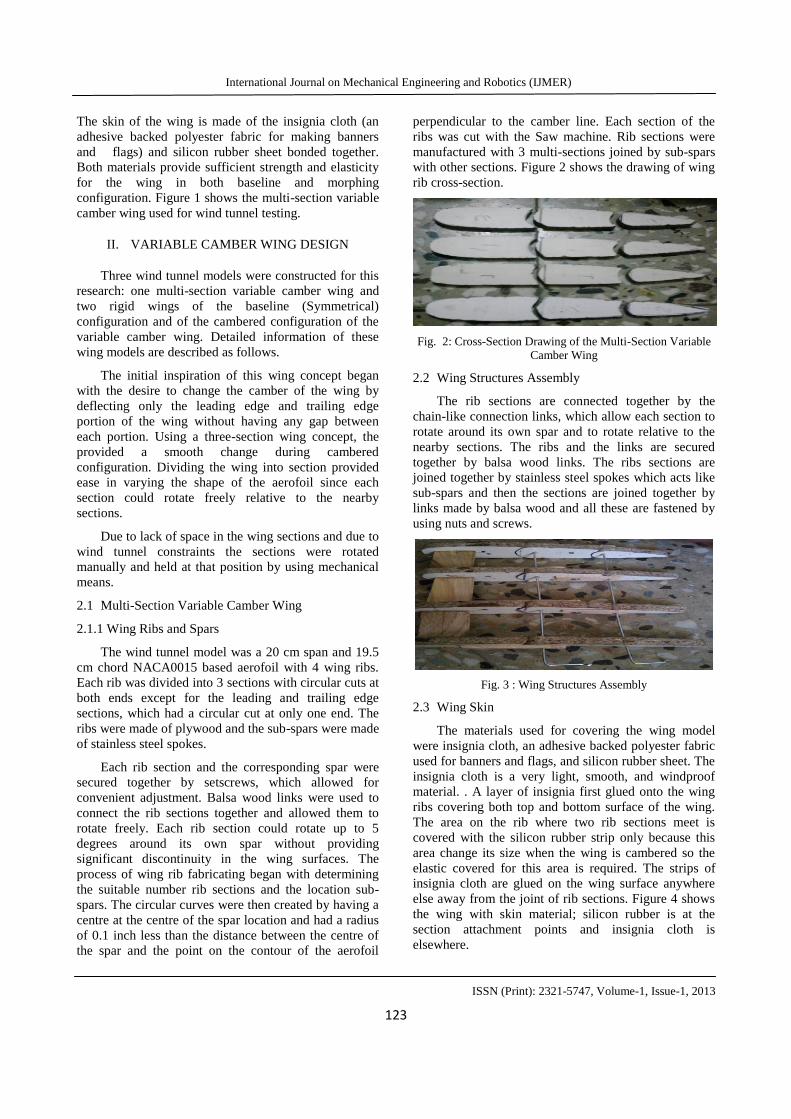
2.2 Wing Structures Assembly
The rib sections are connected together by the
chain-like connection links, which allow each section to
rotate around its own spar and to rotate relative to the
nearby sections. The ribs and the links are secured
together by balsa wood links. The ribs sections are
joined together by stainless steel spokes which acts like
sub-spars and then the sections are joined together by
links made by balsa wood and all these are fastened by
using nuts and screws.
Fig. 3 : Wing Structures Assembly
2.3 Wing Skin
The materials used for covering the wing model
were insignia cloth, an adhesive backed polyester fabric
used for banners and flags, and silicon rubber sheet. The
insignia cloth is a very light, smooth, and windproof
material. . A layer of insignia first glued onto the wing
ribs covering both top and bottom surface of the wing.
The area on the rib where two rib sections meet is
covered with the silicon rubber strip only because this
area change its size when the wing is cambered so the
elastic covered for this area is required. The strips of
insignia cloth are glued on the wing surface anywhere
else away from the joint of rib sections. Figure 4 shows
the wing with skin material; silicon rubber is at the
section attachment points and insignia cloth is
elsewhere.

International Journal on Mechanical Engineering and Robotics (IJMER)
ISSN (Print): 2321-5747, Volume-1, Issue-1, 2013
124
Fig. 4 : Wing with Skin
2.4 Rigid Wing Models
Two rigid wing models for the baseline
configuration and for the cambered configuration were
constructed to compare the test results with those of the
variable camber wing. Both the wings are constructed
by using Wooden Material. First wing is the Baseline
configuration that is the symmetrical configuration wing
of NACA 0015 Configuration this rigid model was
made by Wood with 19.5 cm Chord length and 20 cm
span length. Figure 5 shows Baseline Rigid Wing
(NACA 0015)
Fig. 5 : Baseline Rigid Wing (NACA 0015)
Second Wing is the Cambered Configuration wing
that is wing with NACA 6615 Configuration this rigid
model was made by Wood with 19.7cm Chord length
and 20 cm span length. Figure 6 shows Cambered Rigid
Wing (NACA 6615)
Fig. 6 : Cambered Rigid Wings (NACA 6615)
III. SOFTWARE ANALYSIS
1. Baseline rigid configuration
Aerofoil selected for baseline rigid configuration is
NACA 0015 with chord length 19.5 cm and span 20 cm.
Fig. 7 : Profile of NACA 0015
Fig. 8 : Catia model of Baseline Rigid wing
Fig. 9 : Parameters of Symmetrical wing

International Journal on Mechanical Engineering and Robotics (IJMER)
ISSN (Print): 2321-5747, Volume-1, Issue-1, 2013
125
Fig. 10 : Calculation of lift force in Ansys software
Fig. 11 : Calculation of drag force in Ansys software
2. Cambered rigid configuration
Aerofoil selected for cambered rigid configuration
is NACA 6615 with chord length 19.7cm and span 20
cm.
Fig. 12 : Profile of NACA 6615
Fig. 13 : Catia model of cambered rigid wing
Fig. 14: Parameters of cambered wing
Fig. 15 : Calculation of lift force in Ansys software

International Journal on Mechanical Engineering and Robotics (IJMER)
ISSN (Print): 2321-5747, Volume-1, Issue-1, 2013
126
Fig. 16 : Calculation of drag force in Ansys software
Fig. 17 : Catia model of structure assembly of Multi-Section
Wing
IV. EXPERIMENTAL TESTING OF MULTI-
SECTION VARIABLE CAMBER WING AND
RIGID WINGS
Fig. 18 : Wind Tunnel used for Testing
Fig. 19 :Variable Camber Wing while Testing in Wind Tunnel
Fig. 20 : Six Component Test Set-up showing the variation of
lift and drag
V. COMPARISON OF DATA
5.1 Comparison of Experimental Data of MVCW and
Baseline rigid wing with data of Software Analysis
of Wing:
Fig. 21 : Graph of Coefficient of lift Vs. Alpha

International Journal on Mechanical Engineering and Robotics (IJMER)
ISSN (Print): 2321-5747, Volume-1, Issue-1, 2013
127
Fig. 22: Graph of Coefficient of drag Vs. Alpha
Fig. 23 : Graph of Cl/Cd vs. Alpha
Fig. 24: Graph of Coefficient of lift Vs. Alpha
Fig. 25 : Graph of Coefficient of drag Vs. Alpha
Fig. 26: Graph of Cl/Cd vs. Alpha
Fig. 27 : Graph of Coefficient of lift Vs. Alpha

International Journal on Mechanical Engineering and Robotics (IJMER)
ISSN (Print): 2321-5747, Volume-1, Issue-1, 2013
128
Fig. 28: Graph of Coefficient of drag Vs. Alpha
Fig. 29 : Graph of Cl/Cd vs. Alpha
VI. CONCLUSION AND FUTURE WORK
A Lift derived from the variable camber wing is
higher than that of the rigid wing; this is possibly due to
the vibration of the wing skin that keeps the flow
attached to the wing. For the cambered configuration,
the flexibility of the skin helps to reduce the drag on the
variable camber wing.
The wing skin on top surface of the wing becomes
tighter and smoother as it is being forced to curve. The
bottom surface of wing also becomes tighter due to high
pressure. The software drag derived from the Ansys
software lesser than those derived from the experiment
because of errors occurring during experimental testing.
The increase in lift and decrease in drag of the variable
camber wing in cambered configuration results in a
higher lift-to-drag ratio than that of cambered rigid
wing.
The future of the project will be to implement
electric actuators and a simple linkage system embedded
inside the wing, will be designed as another means to
vary the shape of a wing. Same type of skin material
should be applied to both variable camber wing and
rigid wing to provide fair comparison.
VII. REFERENCES
[1] Pern, N.J., Jacob, J.D., “Aerodynamic Flow
Control Using Shape Adaptive Surfaces,”
Proceeding of 1999 ASME Design Engineering
Technical Conferences, September 12-15, 1999.
Las Vegas, Nevada, USA.
[2] Munday, David, Jacob, Jamey, “Active Control
of Separation on a Wing withConformal
Camber,” AIAA 2001-0293.
[3] Munday, David, Jacob, Jamey D., Hauser,
Thomas, and Huang, George,“Experimental and
Numerical Investigation of Aerodynamic Flow
Control UsingOscillating Adaptive Surfaces,”
AIAA 2001-2837.
[4] Munday, David, Jacob, Jamey, “Active Control
of Separation on a Wing with Oscillating
Camber,” AIAA Journal of Aircraft, Vol. 39, No.
1, 2002.
[5] Pinkerton, J.L., Moses, R. W., “A Feasibility
Study to Control Aerofoil Shape Using
THUNDER,” NASA Technical Memorandum
4767.
[6] Strelec, Justin K., Lagoudas, Dimitris C.,
“Fabrication and Testing a Shape Memory Alloy
Actuated Reconfigurable Wing,”
http://smart.tamu.edu/publications/docs/Proceedi
ngs/SPIE2002/wing/SPIE%20wing%20experime
nts.pdf.
[7] McGowan, Anna-Maria R., Washburn, Anthony
E., Horta, Locas G., Bryant,Robert G., Cox,
David E., Soichi, Emilie J., Padula, Sharon L.,
and Holloway,Nancy M., “Recent Results from
NASA’s Morphing Project,” SPIE Paper
No.4698-11, presented at the 9th Annual
International Symposium on Smart Structures
and Materials, March 17-21, 2002, San Diego,
California.
[8] Simpson, J.O., Wise, S.A., Bryant, R.G., Cano,
R.J., Gates, T.S., Hinkley, J.A.,Rogowski, R.S.,
and Whitley, K.S., “Innovative Materials for
Aircraft Morphing,”Materials Division, NASA
Langley Research Center.
[9] Saggere, Laxminarayana, Kota, Sridhar, “Static
Shape Control of Smart Structures Using
Compliant Mechanisms,” AIAA Journal, Vol. 37,
No. 5, May1999.
[10] Jacob, J.D., “On the Fluid Dynamics of Adaptive
Airfoils,” Proceedings of 1998 ASME
International Mechanical Engineering Congress
and Exposition, November 15-20, 1998,
Anaheim, CA, USA.