Variable-Camber Systems Integration and … Technical Memorandum 4370 Variable-Camber Systems...
46
NASA Technical Memorandum 4370 ., -.i/_: - I- 7 Variable-Camber Systems Integration and Operational Performance of the AFTI/F-111 Mission Adaptive Wing John W. Smith, Wilton P. Lock, and Gordon A. Payne APRIL 1992 / i_ _ :,- (i, q C L ,::_ ;.I_ https://ntrs.nasa.gov/search.jsp?R=19920012951 2018-07-03T12:23:32+00:00Z
Transcript of Variable-Camber Systems Integration and … Technical Memorandum 4370 Variable-Camber Systems...

NASA Technical Memorandum 4370., -.i/_: - I-
7
Variable-Camber Systems Integration
and Operational Performance of the
AFTI/F-111 Mission Adaptive Wing
John W. Smith, Wilton P. Lock,
and Gordon A. Payne
APRIL 1992
/
i_ _ :,-
(i, q C L ,::_;.I_
https://ntrs.nasa.gov/search.jsp?R=19920012951 2018-07-03T12:23:32+00:00Z

_ r
o
r
r I
L

NASA Technical Memorandum 4370
Variable-Camber Systems Integration
and Operational Performance of the
AFTI/F-111 Mission Adaptive Wing
John W. Smith
PRC, Inc.
Edwards, California
Wilton P. Lock and Gordon A. Payne
Dryden Flight Research Facility
Edwards, California
NA.qANational Aeronautics andSpace Administration
Office of Management
Scientific and TechnicalInformation Program
1992


CONTENTS
ABSTRACT
INTRODUCTION
TESTBED AIRCRAFT 2
F-111A Basic Primary Control System ................................... 4AFTI/F-111 Hardware and Mechanical Systems .............................. 5
5AFTI/F-111 Hydraulic Systems ......................................10Manual Hight Control Systems ......................................
Primary and Backup Systems Architecture .............................. 10
Servoactuator Control Systems .................................... 10
HINGE MOMENT ANALYSIS 1415Analytical Modeling and Definition ......... ...........................17Frequency Response ............................................
Predicted Transient Response Influenced by Torque Load ......................... 17
OPERATIONAL PERFORMANCE 2626Hydraulic Pressure Variation With Control Activity ............................30Reliability and Dependability Assessment .................................
CONCLUSIONS 33
APPENDIXmNOMENCLATURE 34
REFERENCES 37
PRECEDING PAGE BLANK NOT FILMED
I°..
111

LIST OF TABLES
Table 1. The mission adaptive wing physical and geometric characteristics ................. 3
Table 2. Hydraulic servoactuator characteristics and analytical constants, reference gain and LVDT gain = 0.77V/deg and range -4-10 V. .......................................... 14
Table 3. Control surface rates and authorities of the variable-camber wing ................. 14
iv
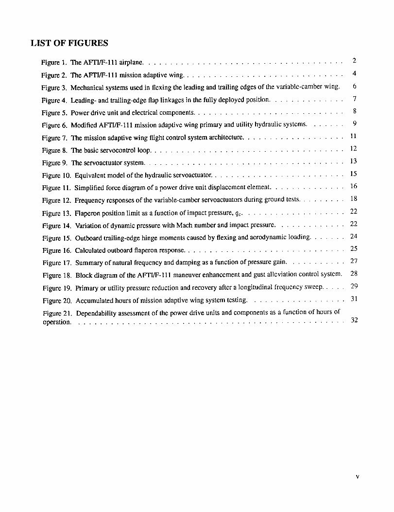
LIST OF FIGURES
Figure 1.
Figure 2.
Figure 3.
Figure 4.
Figure 5.
Figure
Figure
Figure
Figure
Figure
Figure
Figure
Figure
Figure
Figure
Figure
Figure 17.
Figure 18.
Figure 19.
Figure 20.
Figure 21.
operation.
The AFFI/F-111 airplane ..................................... 2
The AFTI/F-111 mission adaptive wing .............................. 4
Mechanical systems used in flexing the leading and trailing edges of the variable-camber wing. 6
Leading- and trailing-edge flap linkages in the fully deployed position .............. 7
Power drive unit and electrical components ............................ 8
6. Modified AFFI/F-111 mission adaptive wing primary and utility hydraulic systems ....... 9
7. The mission adaptive wing flight control system architecture ................... 11
8. The basic servocontrol loop .................................... 12
139. The servoactuator system .....................................
10. Equivalent model of the hydraulic servoaetuator ......................... 15
11. Simplified force diagram of a power drive unit displacement element .............. 16
12. Frequency responses of the variable-camber servoactuators during ground tests ......... 18
13. Flaperon position limit as a function of impact pressure, qc................... 22
14. Variation of dynamic pressure with Mach number and impact pressure ............. 22
15. Outboard trailing-edge hinge moments caused by flexing and aerodynamic loading ....... 24
16. Calculated outboard flaperon response .............................. 25
Summary of natural frequency and damping as a function of pressure gain ........... 27
Block diagram of the AFTI/F- 111 maneuver enhancement and gust alleviation control system. 28
Primary or utility pressure reduction and recovery after a longitudinal frequency sweep ..... 29
Accumulated hours of mission adaptive wing system testing .................. 31
Dependability assessment of the power drive units and components as a function of hours of32


ABSTRACT
The advanced fighter technology integration, the AFTI/F- 111 aircraft, is a preproduction F- 111A testbed research
airplane that was fitted with a smooth variable-camber mission adaptive wing. The camber was positioned and
controlled by flexing the upper skins through rotary actuators and linkages driven by power drive units. This report
describes the wing camber and control systems. The measured servoactuator frequency responses are presented
along with analytical predictions derived from the integrated characteristics of the control elcments. A mission
adaptive wing system chronology is used to illustrate and assess the reliability and dependability of the servoactuator
systems during 1524 hours of ground tests and 145 hours of flight tests.
INTRODUCTION
Modern tactical aircraft (A/C) must perform over a broad operational envelope. A common and practical method
for optimizing the wing at any one flight condition, such as speed and altitude, loading, minimum fuel consumption,
or maximum range, is to adjust both wing sweep and camber to a predetermined favorable value for that condi-
tion. On the other hand, maneuvcrs performed at nonoptimum flight conditions may result in an overall penalty. A
desirable innovation could continuously vary the wing geometry, particularly camber, as a function of a measured
flight parameter or as an integrated set of measured flight parameters. From feasibility studies and aircraft avail-
ability, the F-111A, used for the transonic aircraft technology (TACT) program, was selected as the logical aircraft
for modifiying and developing a mission adaptive wing (MAW). A comprehensive discussion of the TACT/F-Ill
flight test results is given in reference 1. The resulting or new program, employing the variable-camber concept,
was designated as the advanced fighter technology integration (AFI'I/F-111) aircraft.
The objectives and goals of the AFFI/F-111 program were to design, implement, and explore the technology of
a smooth, variable-camber wing. The MAW design incorporated flexible fiberglass skins on the upper leading edge
(LE) and trailing edge (TE). This design enables the upper surfaces, when flexed cordwise, to have a smooth, contin-
uous contour (fig. 1). To affect the complete sectional distortion, the area along the bottom surfaces near the LE and
TE was reduced by using sliding panels overlapping to give minimal discontinuity along the spanwise seams. The
controlled camber curvature was obtained by a cascade of internal mechanisms composed of hydraulic power drive
units (PDU's), rotary actuators, and mechanical linkages. These mechanisms deformed the wing downward starting
at the hinge line. There were eight individually controllable segments, two on the LE's and six on the TE's. Pri-
mary control was commanded and accomplished through a dual-redundant, fly-by-wire, digitally programmed flight
control system. A dual-redundant analog system provided manual backup control. A description of the software,
hardware, and redundancy management systems is reported in reference 2.
The AFTI/F-111 program was divided into two phases. Phase 1 addressed design and construction of the
manual flight control system (MFCS) and extended through part of the flight testing up to the implementation of
the automodes. The phase 2 ground and flight testing addressed integration and implementation of the automatic
flight control system (AFCS). The AFCS design effort had paralleled and was completed during the phase 1 pro-
gram. The AFCS consisted of maneuver camber control, maneuver load control, cruise camber control, and ma-
neuver enhancement and gust alleviation (ME/GA). A description and discussion of the four modes is given in
references 3, 4, and 5.
The foremost objectives of the phase 2 MFCS flight test program were to evaluate handling qualities, flying
quantities, and A/C performance. In addition, the AFCS was evaluated by comparing results with the design predic-
tions. Throughout both flight-test phases, there were no in-flight failures or system deficiencies that compromised
safety or limited the flight-test objectives. A compilation of the AFTI/F-111 program and a summary of the flight-test
results are given in reference 6.

ORIGINAL PAC_
BLACK AND WHITE PHOTOG_APN
Figure 1. The AFTI/F-111 airplane.
This report discusses the AFTI/F-111 variable-camber control segments power actuating systems. A brief de-
scription of the A/C and wing modifications required to install the variable-camber wing is presented. Analytical
descriptions of the MAW servoactuator feedback systems are given along with the predicted closed-loop frequency
responses. The predictions are compared to measured frequency responses obtained during qualification and ac-
ceptance ground testing. Predictions, for example, are used to show the expected transient response during an ex-
ceptionally high dynamic pressure condition when coupled with a corresponding large hinge moment loading. The
power demands of the hydraulic systems are assessed during an in-flight frequency sweep with the ME/GA mode
engaged. In addition, the accumulated hours of MAW system operation are shown as a function of a chronology of
the test events. The various types of failures experienced and the component and unit replacements required during
both phases of the program are numerically tabulated as a function of the accumulated hours of operation.
The AFTI/F-111 MAW program was a combined effort by the NASA Dryden Flight Research Facility (DFRF),
U.S. Air Force, Air Force Flight Test Center, Wright Research and Development Center, and Boeing AdvanccdSystems Company.
TESTBED AIRCRAFT
The following sections provide a general description of the basic F- 111A aircraft, the AFFUF- 111 aircraft config-urations, and the integrated primary control systems for both aircraft. The extensive modifications made to the TACT
wing to implement the AFTI/F-111 variable-camber mechanical systems are highlighted in a limited review. Minor,
but necessary, changes to the primary and utility hydraulic systems of the aircraft to obtain the necessary control
rates and authorities are discussed and illustrated. Basic descriptions and information diagrams of the architecture
are presented showing the signal flow from and to the MAW computers, primary and backup flaps, and flaperon
servoactuator systems. The AFTI/F-111 pertinent physical and geometric characteristics are shown in table 1.
2
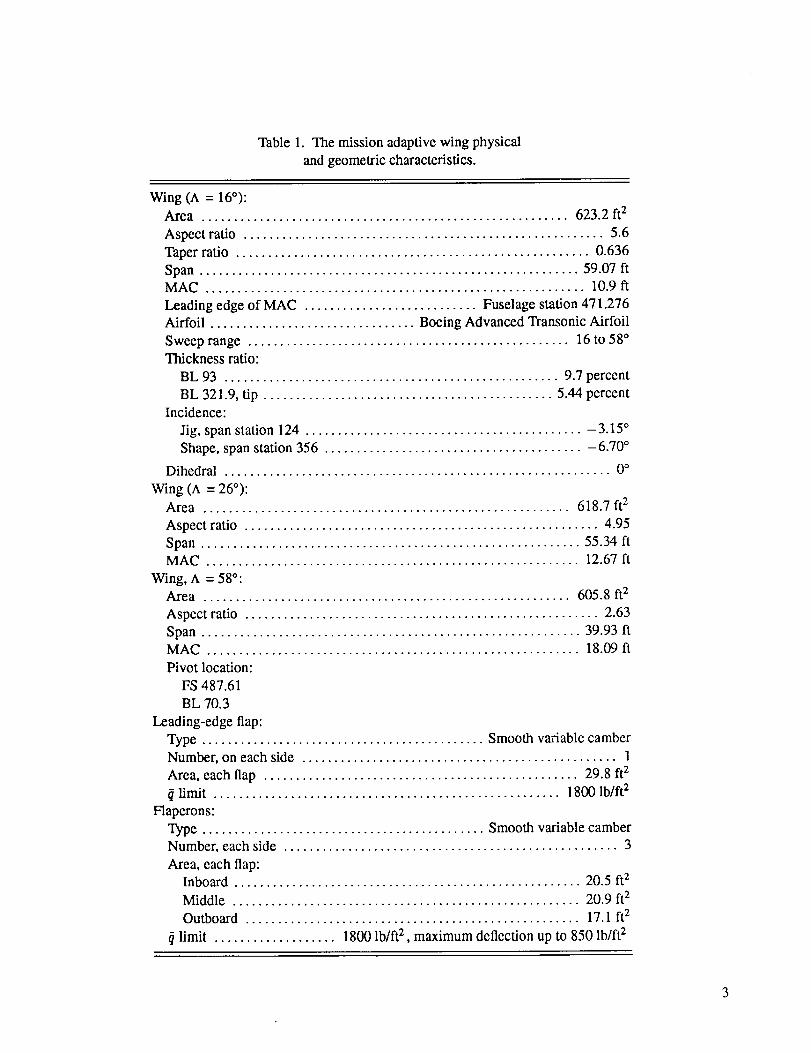
Table1. Themissionadaptivewingphysicalandgeometriccharacteristics.
Wing(A = 16°):Area ......................................................... 623.2ft2Aspectratio ........................................................ 5.6Taperratio ....................................................... 0.636Span........................................................... 59.07ftMAC ........................................................... 10.9ftLeadingedgeof MAC ........................... Fuselagestation471.276Airfoil ................................ BoeingAdvancedTransonicAirfoilSweeprange.................................................. 16to58°Thicknessratio:
BL 93 .................................................... 9.7percentBL 321.9,tip ............................................. 5.44percent
Incidence:Jig,spanstation124........................................... -3.15°
Shape, span station 356 ........................................ -6.70 °
Dihedral ............................................................ 0°
Wing (A = 26°):Area ......................................................... 618.7 ft2
Aspect ratio ....................................................... 4.95
Span ........................................................... 55.34 ftMAC .......................................................... 12.67 ft
Wing, A = 58°:Area ......................................................... 605.8 ft2
Aspect ratio ....................................................... 2.63
Span ........................................................... 39.93 ftMAC .......................................................... 18.09 ft
Pivot location:
FS 487.61
BL 70.3
Leading-edge flap:
Type ............................................ Smooth variable camber
Number, on each side ................................................. 1
Area, each flap ................................................. 29.8 t2
limit ...................................................... 1800 lb/ft 2
Flaperons:
Type ............................................ Smooth variable camberNumber, each side .................................................... 3
Area, each flap:Inboard ...................................................... 20.5 ft2
Middle ...................................................... 20.9 ft 2
Outboard .................................................... 17.1 ft 2
?/limit ................... 1800 lb/ft 2 , maximum deflection up to 850 lb/ft 2

F-111A Basic Primary Control System
The F-111A testbed aircraft, an early version of the production F-111 's, was fitted with a super-critical wing and
was redesignated by NASA as the TACT/F-111 aircraft. The F-111A aircraft, a two-place, side-by-side fighter withtwo engines, could vary the wing sweep from 16 to 72 ° .
Pitch and roll control, in part, are accomplished by stabilons (fig. 2). Additional lateral control was originally
provided by electrically commanded spoilers located spanwise and centered along the upper wing surface. Basic
primary control in pitch and roll was derived by and through a triplex electronic rate command system with an over-
lapping direct mechanical system. In pitch, the stick commands a constant response proportional to the sum of pitch
rate and normal acceleration (t_ + 4A,). The error signal is driven continuously to zero by a series trim actuator
located in the forward loop (type 1 system). In roll, the lateral stick commands roll rate through both the rolling tail
and the spoilers. The actual roll response thus depends on the error signal which is the commanded response minusthe sensed roll rate feedback (type 0 system).
Existing TACT/F-111 wing
Single-segmentvariable-camberleading edge system
Three-segment, variable-cambertrailing edge system
removed
Rollinghorizontalstabilons
Interfaces withexisting electricaland hydraulic systems --
Flight deckindicatorsand control: Inboard flap
Body Midspan andsensors outboard flaperons
Dual flight controlsystem electronics
Second-generationadvanced technology airfoil
Figure 2. The AFTI/F-111 mission adaptive wing.
911151
The feedback rate signal in both the pitch and roll axis provides the artificial damping. Adaptive gain changes
are located in the forward loop of both the pitch and roll axis and are unique to all F-111 A/C. This F- 111A A/C has
the option of manual selectable gains. In the yaw axis, a simple fixed-gain, rate-damper system provides artificial
yaw damping. Lateral acceleration and washed-out yaw rate sum as feedback and proportionally drive the rudderin a typical yaw-damper fashion. All three flight control axes are triplex redundant with middle value selection. A
more comprehensive description of the F-111A control systems is given in reference 7.
4
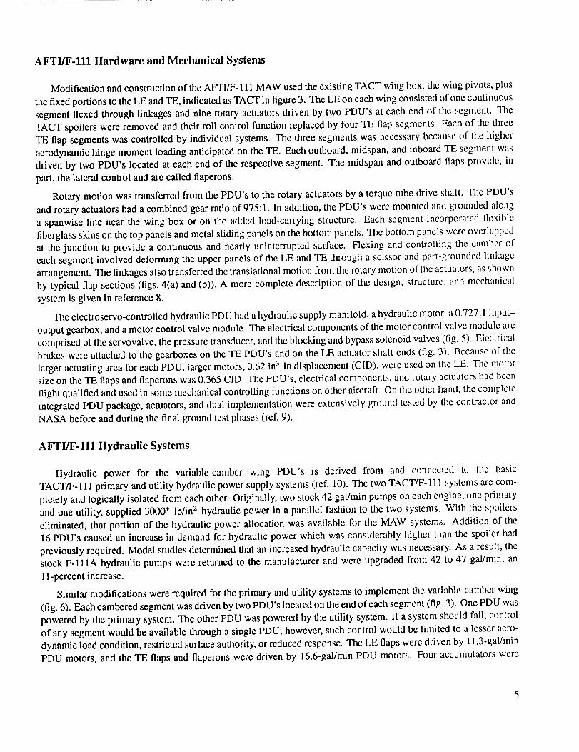
AFTFF-111 Hardware and Mechanical Systems
Modification and construction of the AFTI/F- 111 MAW used the existing TACT wing box, the wing pivots, plus
the fixed portions to the LE and TE, indicated as TACT in figure 3. The LE on each wing consisted of one continuous
segment flexed through linkages and nine rotary actuators driven by two PDU's at each end of the segment. The
TACT spoilers were removed and their roll control function replaced by four TE flap segments. Each of the three
TE flap segments was controlled by individual systems. The three segments was necessary because of the higher
aerodynamic hinge moment loading anticipated on the TE. Each outboard, midspan, and inboard TE segment was
driven by two PDU's located at each end of the respective segment. The midspan and outboard flaps provide, in
part, the lateral control and are called flaperons.
Rotary motion was transferred from the PDU's to the rotary actuators by a torque tube drive shaft. The PDU's
and rotary actuators had a combined gear ratio of 975:1. In addition, the PDU's were mounted and grounded along
a spanwise line near the wing box or on the added load-carrying structure. Each segment incorporated flexible
fiberglass skins on the top panels and metal sliding panels on the bottom panels. The bottom panels were overlapped
at the junction to provide a continuous and nearly uninterrupted surface. Flexing and controlling the camber of
each segment involved deforming the upper panels of the LE and TE through a scissor and part-grounded linkage
arrangement. The linkages also transferred the translational motion from the rotary motion of the actuators, as shown
by typical flap sections (figs. 4(a) and (b)). A more complete description of the design, structure, and mechanical
system is given in reference 8.
The clectroservo-controlled hydraulic PDU had a hydraulic supply manifold, a hydraulic motor, a 0.727:1 input-
output gearbox, and a motor control valve module. The electrical components of the motor control valve module are
comprised of the servovalve, the pressure transducer, and the blocking and bypass solenoid valves (fig. 5). Electrical
brakes were attached to the gearboxes on the TE PDU's and on the LE actuator shaft ends (fig. 3). Because of the
larger actuating area for each PDU, larger motors, 0.62 in3 in displacement (CID), were used on the LE. The motor
size on the TE flaps and flaperons was 0.365 CID. The PDU's, electrical components, and rotary actuators had been
flight qualified and used in some mechanical controlling functions on other aircraft. On the other hand, the complete
integrated PDU package, actuators, and dual implementation were extensively ground tested by the contractor and
NASA before and during the final ground test phases (ref. 9).
AFTI/F-111 Hydraulic Systems
Hydraulic power for the variable-camber wing PDU's is derived from and connected to the basic
TACT/F-111 primary and utility hydraulic power supply systems (ref. 10). The two TACT/F- 111 systems are com-
pletely and logically isolated from each other. Originally, two stock 42 gal/min pumps on each engine, one primary
and one utility, supplied 3000 ÷ lb/in z hydraulic power in a parallel fashion to the two systems. With the spoilers
eliminated, that portion of the hydraulic power allocation was available for the MAW systems. Addition of the
16 PDU's caused an increase in demand for hydraulic power which was considerably higher than the spoiler had
previously required. Model studies determined that an increased hydraulic capacity was necessary. As a result, the
stock F-IlIA hydraulic pumps were returned to the manufacturer and were upgraded from 42 to 47 gal/min, an
11-percent increase.
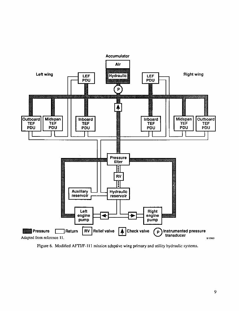
Similar modifications were required for the primary and utility systems to implement the variable-camber wing
(fig. 6). Each cambered segment was driven by two PDU's located on the end of each segment (fig. 3). One PDU was
powered by the primary system. The other PDU was powered by the utility system. If a system should fail, control
of any segment would be available through a single PDU; however, such control would be limited to a lesser aero-
dynamic load condition, restricted surface authority, or reduced response. The LE flaps were driven by 11.3-gal/min
PDU motors, and the TE flaps and flaperons were driven by 16.6-gal/min PDU motors. Four accumulators were

Wing tipfixed section
Outboardflaperon
PDU(0.365 ClD)-
-- Wing tipLE section
Brake
Midspantlaperon
PDU(0.365 ClD)
Inboard TEF
PDU(0.365 CID)
I
\
ExistingTACT
wing box
hie camber LEF
y-gearedactuator
Drive shaftand couplings
PDU(0.62 CID)
Fixed TEsection
Brake
Fixed LEsection (TACT)
Figure 3.
Pivot (TACT)910979
Mechanical systems used in flexing the leading and trailing edges of the variable-camber wing.

Sparcenterline
I
Referenceline
(a) Leading-edge section.
910980
Spar _ ACt;pto°r_ Iii_tkage
centerhne \ /- Nominal airfoil
I \ /-Rotary actu_at_or. / reference position
_2
j-Flex panel epoxy
__ fiberglass
/ -__, _-i-_,v_ / _)'_ Trailing edge
/AuxilZiC:;;ra_ panel ......... L R:p/o::;Skni/) _ _
910981
(b) Trailing-edge section.
Figure 4. Leading- and trailing- edge flap linkages in the fully deployed position.
7

Electrical brak_
_ Rotary _ue tube
actuator(975:1)
/
Gearbox(0.727:1)
I
Torque tube
Rotary
_ actuato r
Quill shaft
Hydraulicmotor
Pressuretransducer
Motor controlvalve module
Electromechanicalserovalve
F
ulicsupply lines
-__1_ 'Bypass solenoid valve
Blocking solenoid valve
Figure 5. Power drive unit and electrical components.
910982
Left wing
Accumulator
Air I
Hydraulic Right wing
TEFPDU
II
MidspanTEFPDU
InboardTEFPDU
InboardTEFPDU
MidspanTEFPDU
I OutboardTEFPDU
Pressurefilter
Auxiliaryreservoir
Hydraulicreservoir
Pressure
Adapted from reference 11.
engine -pump
Return r_ Relief valve
Rightenginepump
-ICheck valve Q Instrumented pressuretransducer910983
Figure 6. Modified AFTI/F-111 mission adaptive wing primary and utility hydraulic systems.
added,twotoeachwingsystem.Whenprechargedto 1100Ib/in2,theaccumulatorsprovidedanadditionalcapacityof 0.87gal/unit.A 1.3-galauxiliaryreservoirwasaddedto theprimarysystemto accommodatetheincreasedcapacityrequiredbytheaddedaccumulators.Ofnecessity,thebasicaircraftutility systemhadsufficientreservoircapacity.A moredetaileddescriptionof theF-111AandMAWhydraulicsystemsandrequirementsisprovidedinreferencesl0 and11.
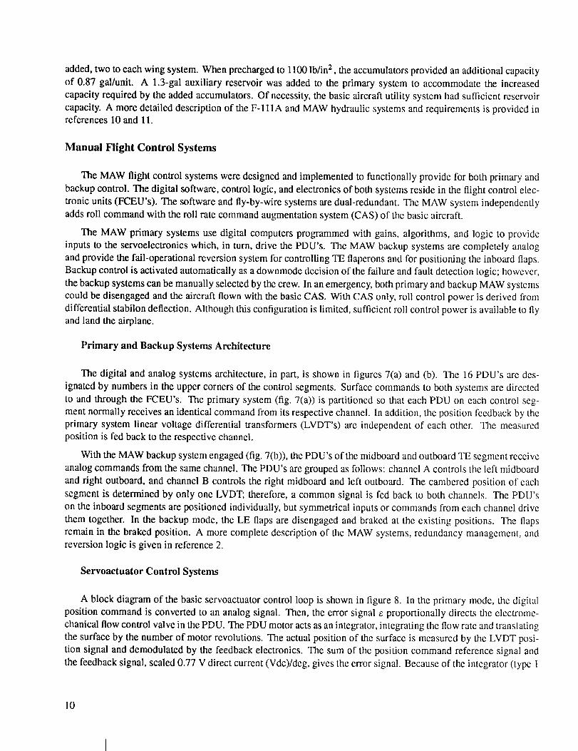
Manual Flight Control Systems
The MAW flight control systems were designed and implemented to functionally provide for both primary and
backup control. The digital software, control logic, and electronics of both systems reside in the flight control elec-
tronic units (FCEU's). The software and fly-by-wire systems are dual-redundant. The MAW system independently
adds roll command with the roll rate command augmentation system (CAS) of the basic aircraft.
The MAW primary systems use digital computers programmed with gains, algorithms, and logic to provide
inputs to the servoelectronics which, in turn, drive the PDU's. The MAW backup systems are completely analog
and provide the fail-operational reversion system for controlling TE flaperons and for positioning the inboard flaps.
Backup control is activated automatically as a downmode decision of the failure and fault detection logic; however,
the backup systems can be manually selected by the crew. In an emergency, both primary and backup MAW systems
could be disengaged and the aircraft flown with the basic CAS. With CAS only, roll control power is derived from
differential stabilon deflection. Although this configuration is limited, sufficient roll control power is available to flyand land the airplane.
Primary and Backup Systems Architecture
The digital and analog systems architecture, in part, is shown in figures 7(a) and (b). The 16 PDU's are des-
ignated by numbers in the upper corners of the control segments. Surface commands to both systems are directed
to and through the FCEU's. The primary system (fig. 7(a)) is partitioned so that each PDU on each control seg-
ment normally receives an identical command from its respective channel. In addition, the position feedback by the
primary system linear voltage differential transformers (LVDT's) are independent of each other. The measuredposition is fed back to the respective channel.
With the MAW backup system engaged (fig. 7(b)), the PDU's of the midboard and outboard TE segment receive
analog commands from the same channel. The PDU's are grouped as follows: channel A controls the left midboard
and right outboard, and channel B controls the right midboard and left outboard. The cambered position of each
segment is determined by only one LVDT; therefore, a common signal is fed back to both channels. The PDU's
on the inboard segments are positioned individually, but symmetrical inputs or commands from each channel drive
them together. In the backup mode, the LE flaps are disengaged and braked at the existing positions. The flaps
remain in the braked position. A more complete description of the MAW systems, redundancy management, andreversion logic is given in reference 2.
Servoactuator Control Systems
A block diagram of the basic servoactuator control loop is shown in figure 8. In the primary mode, the digital
position command is converted to an analog signal. Then, the error signal e proportionally directs the electrome-
chanical flow control valve in the PDU. The PDU motor acts as an integrator, integrating the flow rate and translating
the surface by the number of motor revolutions. The actual position of the surface is measured by the LVDT posi-
tion signal and demodulated by the feedback electronics. The sum of the position command reference signal and
the feedback signal, scaled 0.77 V direct current (Vdc)/deg, gives the error signal. Because of the integrator (type 1
10

Left wing
2LVDT's
Pn'S
LEF
FCEU
Primary ICh 1
Right wing
H 2 HLVDT'sPn'S
FCEU
5 2 6 7 2 8m LVDT's LVDT's
H U Pn's Hp Hp Pn's H U
Outboard Midspan
Adapted from reference 2.
9 2 10LVDT's m
HU Pn'S H p
InboardTrailing-edge segments
Commands ,.._1 Primary IY[ Ch2
Pn s IHuI _H'-_L_D'_s_I _LVD'T'S_H-u1
Inboard Midspan Outboard
910984
(a) Digital primary systems.
LEF braked_ LEF braked
5 1 6m LVDTH U Hp
Outboard
FCEU
Backup IChA
7 1 8 9 2 10LVDT LVDT's m
Hp Hu HU Hp
Midspan Inboard
Trailing-edge segments
FCEU
Commands ,..._[ Backup I"-I Ch B
I,,I , I,'l_,v,o,_ ,vlo,NInboard Midspan Outboard
910985
(b) Analog backup systems.
Figure 7. The mission adaptive wing flight control system architecture.
11

Po,,tion l,2-b,tI°°°°an0----'lO'CI
0.77 Vdc/deg_ 10Vdc
PDUintegrating
function
Mechanical Surface
position
0.77 Vdc/deg
_+10VdcPosition 1
feedback < Ielectronics
Figure 8. The basic servocontrol loop.
LVDT
positiontransducer
910986
system), the error signal is continuously driven to zero; therefore, the actual surface position follows the desired
position commands. The backup servocontrol loops are the same, except for the position command which is scaledand ranged directly as Vdc feedback.
In the primary mode, identical dual-channel systems position and control the variable-camber segments. Figure 9
is a block diagram of a typical flap showing the complete dual-channel structure of the servoactuator control systems.
This figure also shows the equalization and paired variable-camber control. Except for slight gain changes, this
example is common for all eight variable-camber control segments. The complete system characteristics, including
uncommon gains, are given in table 2 for each control segment. The two channels shown by the FCEU's and
servoelectronics employ error and delta pressure equalization loops to minimize the force-fight that may developfrom separate PDU mechanical inputs to a common torque shaft. Almost identical commands from the FCEU's are
summed, respectively, with the individual LVDT feedback signals. The two error signals are compared. Next, one-
half of the difference is added and subtracted to the actuating signal of each channel. Thus, error equalization loopsgive identical actuating signals regardless of the feedback.
Pressure equalization minimizes, in part, the force-fight caused by the offset difference in the driver amplifiers
and servovalves. Pressure sensors detect the delta pressure across the valve that, when compared, is indicative of thc
pressure reaction caused by the opposing torques. Electrical difference is used for feedback and summed with the ac-
tuating signal. The assigned gain on the compared signal was experimentally determined using a full-scale mockup.
The maximum rates and control surface authorities are listed in table 3. The midspan and outboard llaperons that
supplement the roll power produced by the rolling tail were designed to respond at 40 deg/sec. The maximum upward
travel of all surfaces is limited to approximately - 1°, and the maximum downward travel is approximately 20 °. Morecomplete descriptions for the position and pressure equalization and failure limitations are in reference 12.
12

I> .T I
I°
¢_',-U.
IIIIIII I
r
o
13

Table2. Hydraulicservoactuatorcharacteristicsandanalyticalconstants,referencegainandLVDTgain= 0.77V/degandrange-t-10 V.
Element and Function
System gain, Ke = (KA x 57.3 x 0.77)
Units
V
Leading
Edge
KA = 3.04
Ke = 134.13
Inboard
KA = 1.92
Ke = 84.71
Midspan
KA = 1.08
Ke = 47.65
Outboard
KA = 1.08
Ke = 47.65
Pressure equalization gain: Kp Kp = 0.124 Kp = 0.110 Kp = 0.09 Kp = 0.09
mA KD = 4.0, rD = 0.0025Valve drive amplifier, first order: KD, rD -V-
in. Ksv = 0.0023, %v = 0.0227Servovalve, first order: K.,,, r,v _--
Servovalve flow gain, Kq
Pressure gain, _ 4- Pr
Motor displacement, gain:1
Integrator,
in 4
it).,
tad
s¢c
rad
Gear ratio, motor to actuator; t__r_
Gear ratio, actuator to surface:
Feedback filter, first order: KF1
Kq = 66.167
P, = 2925, Pr variable
10.05809
l
1 10.05809 0.05809
1 i l 13.43 2 .g19 1.969 _ .969
0.0032 a+ I
3142
_2+2 x0.5 x314._+3142Feedback filter, second order: KF2
Table 3. Control surface rates and authorities
of the variable-camber wing.
Position limits, deg
Control surface Rate, deg/sec Up Down
Leading edge 10 -1.07 20.63
Trailing edge:
Inboard flaps 30 - 1.08 17.87
Midspan flaperon 40 -0.69 19.74
Outboard flaperon 40 -0.71 19.59
Source." Reference 2.
HINGE MOMENT ANALYSIS
The variable-camber TE is usually positioned near zero or in a downward direction. The flaperons are differen-
tially flexed from that position. When the control segments are down, there is always some constant hinge moment
torque on the mechanical system caused by flexing the upper surface. In flight, when aerodynamic forces are present,
the TE hinge moment torques are generally much larger than torques on the ground. These two torque moments are
additive and totally opposing to any further downward travel of the flaperons. On the LE, however, the correspond-
ing hinge moment torques are normally less than those torques experienced on the TE. These corresponding torques
may sum up as alleviating forces, depending on the amount of twist and the local angle of attack. In subsequent
sections, these hinge moment torques are treated as feedback functions that change the pressure gain according to
the magnitude of the torque and whether the control flap is moving up or down.
14

Analytical Modeling and Definition
During the preliminary design phases, it was necessary to know the predicted hinge moment torques reflected as
force feedback through the mechanical system back to the PDU motors. Wind tunnel tests were conducted to obtain
the aerodynamic hinge moment coefficients of the surfaces at various cambered positions. Then, these data along
with desired rates were used to size the hydraulic systems, complete the final design, and provide the schedules
for limiting the surface authority as a function of impact pressure. Figure 10 shows an analytical model of the
servoactuator control system. System parameters and constants used in subsequent calculations are listed in table 2.
Generally, the gains, time constants, and gearing ratios in table 2 were used during the simulation and were taken
from reference 13.
PF Both systems operating: KF = 0.5
I Single-system operation: K F = 1.0
L ] PDU and rotary I"............................... I actuators I........ i" _ '! !
! i Ac
.............. con;- ;2 ...................'
910988
Figure 10. Equivalent model of the hydraulic servoactuator.
Describing and predicting the exact characteristics of the servoactuator presents some difficulties because of the
nonlinearity of the pressure gain term x/P, 4- Pr (fig- 10). As shown, this term depends on the external torque and
governs the rate of flow. Basically, the rate of flow Q in a hydraulic servoactuating system is proportional to the
square root of the pressure drop (q <x V"A'-P). For systems where external load forces Fr are present, the net vector
force across the face of each piston or displacement element is shown in the simplified force diagram (fig. 11) where
PR = return pressure, approaching zero,
P, = operating or supply pressure drop,
Fr = generalized total force, aerodynamic plus the flexing load, and
FN = net resultant force caused by P, and Pr.
Because of the high gear ratio, the external load Fr is considered constant for each displacement element in the PDU
motor as
Fr = Pr x A (1)
15

Mass
iXo m]
Surface dynamics
Ps
PR (Open) PR (Closed)
Left Right"_" _ High gearing: _t = 709
Pressure drop Ps Small change in FF with
_ L displacement
It--, Jl_F = totVlalexter___ai force_
Figure 11. Simplified force diagram of a power drive unit displacement element.
911175
Thus, Pr is thought of as a mechanical pressure, the result of the external load, so that movement to the left would
cause a net force equal to
/_=P_ x A+/_ x A= (Ps+ Pr) A(up flap) (2)
The net force in movement to the right would be
"'-4,
/_ = P, x A+ i_r x A = (P, - Pr) A(down flap) (3)
Because the return pressure approaches zero, the total pressure drop is the algebraic sum
G-t-Pc (4)
This value depends on valve position; therefore, the rate of flow integrated by the PDU motor is expressed in thecommon fashion as
Q = xv KQx/G + Pr (5)
where
Xv = servovalve position,
KQ = servovalve flow gain, and
+ Pr = pressure force gain.
From equation (5), Q depends on the product of the valve position Xv and the magnitude of x/Ps ± Pr. The
sign for the external force Pr is maintained analytically by the external loop (fig. 10).
In figure 10, the input A R is considered a small change about a trimmed condition. The control variable a C is
the resulting change in surface position about the trimmed condition. During a frequency sweep, the total torque FT-
causes either a back or an aiding pressure at all frequencies. This pressure alternately changes once over each control
cycle; thus, the force gain x/Ps + Pr depends on the external torque FT- and supply pressure P8 plus the sign of the
control value Xv. The force gain is, therefore, related to the closed-loop phase. It follows, then, that the pressure
16

gainis relatedto thedynamiccharacteristicsof the system. Because the pressure gain is not constant, the extent
of any linear analysis may be somewhat limited. Consider a condition with no aerodynamic loading, like on the
ground, and with the outboard segment flexed all the way down. The total measured flexing torque is approximately
10 x 10 3 in.lb. With both PDU's operating, Kr = 0.5. The resulting change in hydraulic pressure would be
1 1F_r x Kr x -- x = 121.45 lb/in 2 (6)
For a 3000-1b/in 2 system operating at a typical supply pressure of 2925 lb/in 2, the expected variation in pressure
gain is
52.9 (down flap) < x/_-'ss+ Pr <_ 55.2 (up flap) (7)
As indicated, the variation in pressure gain caused by flexing is small. Consequently, the variation in frequency and
transient response characteristics of the servoactuator would also be small. At high aerodynamic load conditions,
however, this variation can be large, as shown later, and would require schedules to limit the authority of the flapsand flaperons.
Frequency Response
Frequency response tests were conducted by DFRF as part of qualification and acceptance testing. The tests
were performed on the ground; consequently, the servoactuating system would only be experiencing the flexing and
inertia loading. All surfaces were initially trimmed halfway down, approximately l 1°. Random noise test methods
were used with a signal analyzer, at a noise source level of 2 ° peak-to-peak, and over a frequency range of 0.5to 25 Hz.
The measured and predicted frequency responses obtained for the LE, inboard, midspan, and outboard segments
are shown in figures 12(a), (b), (c), and (d). The solid and dashed lines are the comparison between the right and left
sides, respectively. The agreement between the right and left sides is consistent over the frequency range for all the
segments. In particular, the flaperons, which constitute the primary control, show good agreement throughout. No
lightly damped modes were detected over the frequency range investigated. Hysteresis was measured at the LVDT's
during separate tests. When converted to surface travel, the threshold band was approximately +0.06 °. With a 2 °
peak-to-peak input, the perceptible level was above -24.5 dB, as indicated in the figures.
Analytical linear predictions were made using the values given in table 2. The results are indicated in figures
12(a) to (d). In general, the amplitude ratios are matched by the predictions. The phase, however, indicates more lag
from the tests at the higher frequencies than the analytical model or transfer functions predict. The transfer functions
derived from the closed-loop model are also presented in the figures. A second-order approximation can be obtained
simply by canceling the higher order roots. This approximation typifies a control system having a natural frequency
of approximately 30 rad/sec and a damping ratio between 0.51 and 0.62.
Predicted Transient Response Influenced by Torque Load
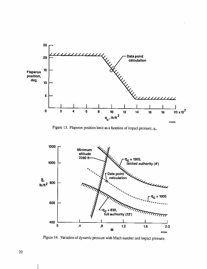
An example flight condition was selected near the maximum aerodynamic hinge moment torque loads, impact
pressure qc = 1000 lb/ft 2, to show the effect of torque on the servoactuator transient response. Figure 13 shows a
MAW schedule that limits flaperon travel as a function of qc. For the example calculation, the maximum flaperon
travel is limited to approximately 15° . The wind tunnel hinge moment coefficient data in reference 13 were used
to determine the torque loads. The maximum coefficient values occurred near Mach 0.9. Figure 14 shows the dy-
namic pressure as a function of Mach number at a constant qc = 1000 lb/ft 2 and the q¢ bounds for flaperon authority
at 830 <_ qc < 1360. The dynamic pressure _ is approximately 820 lb/ft 2 . Hinge moment torques wcre dctcrmined
17

0 0 0 0 0 0
I
I I I I I
•-"_ ,
-_o _..., "r.., I •
_'-_E_¢_ 0 0)=g c_ n- j. 0 0 /
0
/ W' :
,2" /,- +, • _'4,' ¢,," %
,I 7," x N
r / g' I x _-
¢ ol _0 "/ _ +
n / _ ¢",4i | :< (n
+
O
+
I I I I I I I0 0 0 0 0 0 0 0
I I I I I I
oo
o
N-r
"o
o
e.0
c_
,._ .,-.
Cr
c4
18

0 0 0 0 0 0
I I I I I I
",,,,, E ._- "o m _,I- 4) m--'I_ __" I_ I- .I_ lr)
A.'- l _'" I+/, \ / ," I m
/__/ _ \/ o" ,.:
o ?,, X _"' J? ___ +
O' o_ m -
Ii x _.,I; o .&_
oliO3
+b3
o)
+
I I I I I I I ,-:.0 0 0 0 0 0 0 0
_" _ I I I I
IJ. _OU
@
19

!0
o 0 0 0 0 oco Cd a_ _ 0
,, I I I I I I
,-,,, _ .-_®b,
"E'o _ _ o. >,r- , k"
1, x _-I; ,_,
ol _. -x cN
o1: _
I I I I I0 0 0
I
+
+
V
I0 0
I I
o
LE
2O

_o"0
0
0
0
I I I I I Io o o o o o
o
_ N
21
Flaperonposition,
deg
25
20
15
10
5
0
/ / / / ///////////_, /--Data pointation
-- .%,.////// //////
I I I I I I I I I I2 4 6 8 10 12 14 16 18 20 x 102
qc' Ib/ft2910993
Figure 13. Flaperon position limit as a function of impact pressure, qc.
1200
1000
I
q' 800Ib/ft 2
6OO
400
Minimum _.altitude
2280 ft__. /-qc = 1360,
.J_ _ mited auth°rity (4°)
""*'.... qc = 1000
I I I I I.4 .8 1.2 1.6 2.0
M910994
Figure 14. Variation of dynamic pressure with Mach number and impact pressure.
22

from the coefficients and dynamic pressure and are given in figure 15. The FA was determined from wind tunnel
data at M = 0.9, _ = 820 lb/ft z , LEF = 0.0, and A = 26 ° (ref. 13). Flexing torque FF and hinge moment torque as a
result of aerodynamics IrA are shown as a function of the outboard flaperon position. The equations for each curve
are also given. Total torque for the example prediction at 15° deflection is
FF + FA = --90 x 10 3 in.lb (8)
The pressure change is determined for an outboard flaperon servoactuator trimmed at 15° by using the maximum
estimated torque. From figure 10 and table 2 with both PDU's operating at Kr = 0.5,
1 1 XvPr = FT- x Kr x -- x x - 4-1093 lb/in 2 (9)
For a single PDU operating at Kr = 1.0,
PF = 2186 lb/in z (10)
Thus, for a 3000-1b/in 2 system operating at a supply pressure of P, = 2925 lb/in z, the predicted pressure gain variation
with both systems operating is
42(down flap) < ,v/_s 4- Pr <_ 63(up flap) (11)
For single-system operation,
For no torque loads,
27(down flap) < v'-P-_ -t- Pr _< 72(up flap)
x/-P_s= 54
(12)
(13)
The predicted linear transient responses of the example servoactuator systems operating at three different gains
are shown in figures 16(a) and (b). The calculations were based on the following nonvariant conditions:
TEF = 15 °
M=0.9
qc = 1000 lb/fl 2
FT- = -90 x 103 in-lb
Ps = 2925 Ib/in 2
Kr = 0.5 both PDU's
Kr = 1.0 single PDU
The rate limit boundaries are based on a 4-5 ° step input. With both PDU's operating (fig. 16(a)), all curves
exhibit responses with slight overshoots typical of linear second-order systems with damping ratios between 0.5
and 1.0. For a 5° step input with no hinge moment (V'-_ = 54), the transient responses of the basic servoactuating
system would be rate-constrained when the output exceeded 40 percent of the input. The upward response, with an
alleviating hinge moment (x/Ps + Pr = 63), would be rate-constrained starting when the output exceeded 30 percent
of the input. The downward step input, against an opposing hinge moment _ - Pr = 42, reduces the transient
response to a full linear system. Figure 16(b) shows the responses with one PDU operating. It is like doubling
the hinge moment function to the same servomechanism of Kr = 1.0. Comparisons are made to the basic system
with no hinge moment function that has a damping ratio of _ = 0.62. When the servoactuator is aided by the pres-
sure gain PV_'_s+ Pr = 72 following an upward step input, the damping ratio is reduced to ( = 0.5. A downward step
23

in. Ib
40 x 103
2O
-20--
-40 --
-60 --
-80 --
-100-4
FF = --(700 + 437 x TEF),
flexing gradient .
_--_ Flaperon =15 ° """"
Datapoint
I I I I I I0 4 8 12 16 20 24
5 degSource: Reference 13. TE'
910995
Figure 15. Outboard trailing-edge hinge moments caused by flexing and aerodynamic loading.
24

Output/input,
percent
120
100
80
60
4O
20
0
Referenceinput
• //////
I I.1 ,2
Time, sec
(a) Both power drive units operating at Kr = 0.5.
Rate limit boundary(40 deg/sec) for5° step input
Basic system -no hinge moment
Increasinghinge moment
Decreasinghinge moment
,3
910996
Output /input,
percent
120
100
8O
6O
40
20
0
Reference
input
.1
otem • _a mwmQ_eD i= m_l=m='==l== •
o,O'°'•'" "'" " " ///_--_/ R_te limit boundary
(40 deg/sec) for5° step input
Basic system -no hinge moment
............. Increasinghinge moment
Decreasinghinge moment
Time, sec
,2
(b) One power drive unit operating at Kr = 1.0.
Figure 16. Calculated outboard flaperon response.
.3
910997
25
response, against the hinge moment _ - Pr = 27 results in a system that is almost critically damped. As before,
rate limiting would also constrain the output response of both the single-PDU system aided by the hinge moment
and the basic system with no hinge moment.
The MAW variable-cambered control surfaces can be closely approximated by a second-order system, where the
roots are equated to the natural frequency and damping. Typically, the roots vary with gain. In most cases, the roots
become more oscillatory and less damped as the closed-loop gain increases. The outboard servoactuator dynamic
characteristics are summarized in figure 17, where the pressure gain is considered the independent variable. An
opposing or downward input decreases the frequency and increases the damping ratio. For single-PDU operation,
which doubles the torque load, the damping ratio approaches critical. In the upward commanded input, however,
the aiding torque load causes the frequency to increase and the damping ratio to decrease.
OPERATIONAL PERFORMANCE
Hydraulic Pressure Variation With Control Activity
The greatest demands on the hydraulic systems occurred when the ME/GA mode was engaged and cycled con-
tinuously. This automode performs a dual task: to improve the airplane normal acceleration response from pilot
commands and to reduce the vertical acceleration at the cockpit as a result of turbulence. Figure 18 shows a sim-
plified block diagram of the ME/GA mode. With the mode engaged, the LE and TE of both wings were flexed
symmetrically for direct lift control. The TE flaperons were flexed differentially for manual or augmented roll con-
trol. In addition, a cross-feed loop stabilon command was added to the basic CAS system to properly blend, phase,
and obtain the desired vertical response of the A/C.
Moderate frequency sweeps were conducted in-flight to determine the variation in normal acceleration at the
cockpit. The first sweep was performed with the basic CAS system at flight conditions of
M = 0.75
?/= 325 lb/ft 2
A =26 °
LEF = 7 °
TEF = 9 °
to establish the peak-to-peak stabilon input, 5° peak-to-peak, over a frequency range of 0.3 to 2 Hz. At maximum
control rate, the reduction in Ps of the primary and utility systems was slightly less than 100 lb/in 2. Then, the
frequency sweep was repeated near the same flight conditions but with the MEIGA mode engaged at KMEGA = 0.4.
The results of this test are shown in figure 19. The stabilon control activity, not shown, was approximately 5° peak-
to-peak, and the TE camber varied approximately 3 ° peak-to-peak. The peak-to-peak change in the LE was less than
1°. At the maximum control rate of 2 Hz, the/:'8 for both systems was reduced to 2460 lb/in 2. At the conclusion of
the sweep activity, the P_ recovered in typical exponential fashion. Approximately 2.4 sec were needed to recover
from 2460 Ib/in 2 to 90 percent of the maximum operating supply pressure Poo = 3250 lb/in 2 . By fitting the constants
from the experimental data, the following was derived:
Ps = Poo( 1 - 0.243e ff-27) (14)
where
Poo = 3250 lb/in 2 (15)
26

n,rad/sec
¢
40
30
20
10
0
1.0
.8
.6
.4
.2
0
Figure 17.
6! I! I
+I
!
1
I
' <5I
I
[] I
I I
0 ',
0 Operating supply
pressure
[] Torque load
- 90 xlO 3 in- Ib
both PDU's ( Kr. = 0.p
Maximum A/C _ Torque load
pump pressure 3250-_ \I -and90singlex103 in.PDuIb(K F = 10)
I , _1 I I
I20
I
!
I
I
Flaperondown
fiI
0i!
I
I
I
I
• Flaperonup
I , I40 60
_/Ps- PF _ _/Ps + PI-"
I I80 1O0
910998
Summary of natural frequency and damping as a function of pressure gain.
27

0
0
0"_._
,,_
&e_
E
e.-,
E
<
o
&
0 ,-!
28

LEF,deg
TEF,deg
Psprimary
orutility
system,Ib/in 2
15
10
5
0
15
10
5
0
3500
3000
2500
2000
1500
1000
m
D
I I I I I
m
I I 1 I I
m
///////////////////_-- Pot= 3250
/'-- Accumulator// precharged
- / (11001b/in2)I/////"'///////// I
Failed level // [ e -t--_-z.//(1200 Ib/in 2) -7 [--P = Poo_1 -0.243
/ when t R = 0
P = 2460 Ib/in 2/////////////////////////
I I I I
0 10 20 30 40 50Time, sec 940999
Figure 19. Primary or utility pressure reduction and recovery after a longitudinal frequency sweep.
29

At the recovery point,
tR=0
P_ = 2460 ib/in 2 (16)
The accumulator precharged pressure of 1100 lb/in 2 is indicated by the boundary. At 1200 lb/in 2, the primary system
was programmed to default to the MAW backup mode.
Reliability and Dependability Assessment
The broad objectives of the phase 1 MAW program were to design, install, and flight test the variable-camber
wing employing the MFCS. The MFCS operates in an isolated manner parallel to the existing F-111A CAS system
so as not to affect the existing forward-loop control function of CAS. In addition, the overall design of the MFCS had
to remain fully operational when the AFCS was added. These limitations permitted no modifications to the MAW
servoelectronics and mechanical actuating systems (fig. 9). All automode systems, particularly those automodes that
interfaced with the basic F-111A CAS, were required to be compatible with the MFCS and CAS.
The variable-cambered wings and MFCS computers were installed at DFRF. In November 1983, the fully
installed systems were powered-up for the first time. Figure 20 shows the cumulative hours of ground and flight
testing following a chronology of the various test events. During the initial checkout, 40 hr of operation were required
to develop and affirm the sweep functions, to adjust the LVDT's, and to complete the functional checks of the MFCS
computers and mechanical systems. The outlined preliminary and formal verification and validation (V&V) test
procedures of the MFCS (ref. 9) required approximately 380 hr. The NASA qualification and acceptance testing,
also part of the V&V commitment and the combined system testing, required less than 35 hr. Test results showed
that MFCS computer modifications were necessary. A 5-mo delay in the program followed to change and update
the computers and to complete the documentation reported in reference 14.
Retesting the computer modifications and developing a hangar preflight procedure required approximately 40 hr.
Although the MAW control segments were in a static state during the loads calibrations, the MAW systems were
operated for approximately 125 hr. The complete V&V testing, retesting of all functions, and testing of the basic
F-111A system functions before the first flight required an additional 120 hr. In total, the MAW systems were
operated 840 hr before flight. The first flight occurred October 18, 1985. Twenty-six flights completed the phase 1
MFCS program. During these 26 flights, 58 hr of flight time and an additional 250 hr of MAW systems ground
operations accumulated.
Installation of the automode computers, ground and flight testing of the AFCS, and continued flight testing of
the MFCS was accomplished during the second phase of the MAW program. A brief history, starting with the design
requirements, the milestones, and a summary of the flight test results, is in reference 6.
The second phase began with the completion of flight 26. The first flight of the second phase, flight 27, occurred
more than 9 mo later. During this period, the AFCS computers were installed, and the automode sensors and stabilon
commands were calibrated. Following implementation of the automodes, the integrated MAW AFCS was function-
ally retested with a revised version of the V&V procedures (ref. 14). In addition, the hangar preflight procedures
were changed to include the addition of the AFCS test sections. Before the AFCS was used in flight, ground reso-
nance tests (GRT's) were conducted. These tests satisfied concerns about the ME/GA mode and its ability, through
filters, to stabilize adequately the structural modes. The GRT's, with the ME/GA mode engaged, showed a lack of
sufficient gain margin at the first wing body bending mode, 4 Hz, and the stabilon first symmetric bending mode,
12.8 Hz. Thus, the AFCS computers underwent modifications that required changing the filters and incorporating
variable gains in the ME./GA mode feedback loops.
Between flights 26 and 27, the MAW system was ground tested for approximately 170 hr. Because of the
computer modifications, flights 27, 28, and 29 were flown with only the MFCS. During flight 30, the more benign
30

I I0 0 0 0 0 0 0 0 0 0
i,,,,
t"
I=I
E
"E:i
0
o
"I
0,.,C:
.,-,tt,,It.,,,t
<<::5t'",l
=l
31

automodes were engaged for the first time. Limited AFCS flight testing continued up through flight 35, and 70 hr
of ground operation were added. The complete integration of the automodes, a second GRT to verify ME/GA
mode stability, and a periodic inspection of the MAW system and aircraft added another 100 hr of ground system
operation. In addition, routine tests and hangar preflights added approximately 84 hr of ground operation before
the flight test program was completed. The last flight was flown in December 1988. A total of 145 hr of flight and
1524 hr of MAW system ground operation were accumulated. The 1669 combined hours represent the accumulated
hours that the hydraulic systems were in operation. The control segments were operated sporadically and seldom
cycled continuously; therefore, it is difficult, if not impossible, to estimate the total control cycles. In performing
the primary lateral control function, however, the TE flaperons were undoubtedly cycled many times more than the
LE and inboard flaps.
The variable-camber mechanism had a service life of 11300hr as a design requirement (ref. 8). During the entire
program, the 46 rotary actuators never failed nor was it necessary to replace a rotary actuator unit. The 16 PDU's
did, however, require 37 component or full-assembly replacements. An account of the component or assembly
replacements as compared with the accumulated hours of operation is shown in figure 21. The symbols in this figure
show the component or assembly replaced and major failures. A sketch of a PDU is shown in figure 4. Most of
the inital replacements or overhauls were caused by localized contamination that developed within the first 4130 hr
of system operation. Towards the end of the program, above 800 hr, leaks gradually developed around the motor
shafts. Minute wetness was acceptable; however, if collectable drops were present under pressure conditions, the
motor seals were replaced. During the last 250 hr of operation, no component or unit replacements were necessary.
The six major failures would have downmoded the systems to at least backup and would have required single-PDU
operation or, perhaps, the affected segment would have required braking. All six major failures occurred on thc
ground. No major failures occurred during the last 700 hr of operation. Most important, there were no in-flight
failures, as previously reported in reference 6.
Replacementsor
failures
40 -
32 -
24 -
16 -
0
I 37 replacements.Phase 1 ._
O Control module 1153 hr -i_]______' _assembly Phase 2
r_ Motor J I P5h'6sh2-->
Brake ¢_
I:> PDU assembly
_' Major failures = _
_ H 1-840 hr of groundI testin.._lbefore
first fhghtI,_irst flight F-Broken LVDT wire
_ _--Loose solenoid wire 1669 hr/-Broken ] /E_" _-_ .......... _._-_ . l
_roken pressure XDCR wire I- ng I ._--Ouifl she. [
I I _" I II I I I I T' I200 400 600 800 1000 1200 1400 1600 1800
Time, hr911001
Figure 21. Dependability assessment of the power drive units and components as a function of hours of operation.
32
CONCLUSIONS
The advanced fighter technology integration aircraft, a preproduction F-111A aircraft, was fitted with a smooth
variable-camber mission adaptive wing. Sixteen power drive units and 46 rotary actuators produced active variable-
camber control. During the entire phase 1 and 2 program, 1524 hours of ground testing and 145 hours of flight testing
were accumulated with the mission adaptive wing servoactuator mechanisms operating. Analytical predictions were
acquired to complement the measure frequency responses.
The following conclusions were reached from the ground tests, flight tests, and analytical predictions:
1. The mission adaptive wing system servoactuator mechanisms exceeded the 1000-hours service life require-
ment by 67 percent.
2. There were no rotary actuator failures or replacements.
3. Error signal and pressure equalization loops were effective in minimizing force fights.
4. During an in-flight frequency sweep with the maneuver enhancement and gust alleviation automode engaged,
the mission adaptive wing hydraulic system showed adequate flow capability and recover response.
5. The analytical linear calculations of the closed-loop servoactuator model matched the measured amplitude
ratio. The phase angle was acceptable for up to twice the natural frequency.
6. Successful primary and backup control was provided by the mission adaptive wing systems with no in-flight
failures during the flight tests.
7. During ground operation, 37 power drive unit components or full-assembly replacements were necessary, and
6 major failures that would have downmoded the systems to backup occurred.
8. There were no major failures during the last 700 hours of operation. In addition, no component or unit re-
placements were necessary during the last 250 hours of operation.
33

Abbreviations
A/C
AFCS
AFTI
AR
BL
CAS
Ch
CID
CST
DAC
Demod
DFRF
FCEU
FLT
FS
GRT
KMEGA
LE
LEF
Lim
LVDT
MAC
MAW
ME/GA
MFCS
PDU
RV
TACT
TE
TEF
V
Vdc
V&V
APPENDIX
NOMENCLATURE
aircraft
automatic flight control system
advanced fighter technology integration
amplitude ratio, deg/deg
butt line, in.
command augmentation system
channel
in 3 in displacement
combined system tests
digital to analog
demodulated
Dryden Flight Research Facility
flight control electronic unit
flight
fuselage station, in.
ground resonance test
ME/GA mode gain
leading edge
leading-edge flap, deg
limiter
linear voltage differential transformer
mean aerodynamic chord
mission adaptive wing
maneuver enhancement and gust alleviation
manual flight control system
power drive unit
relief valve
transonic aircraft technology
trailing edge
trailing-edge flap, deg
volts
volts direct current
verification and validation
34

Letter and Mathematical Symbols
A
A.
C
Dm
e
F_
Fr
G.,
Hp
Hu
KA
KAy
KD
K_
KF
Kp
KQ
K_.
Kr
M
m
mA
P
PR
P,
¢P7 + P_
Pr
P_
P_
Q
qc
R
8
t
tR
area, in 2
normal acceleration near the cockpit, g
control variable
motor displacement, in 3/rad
natural logarithm base
net force due to pressure element area, lb
generalized force due to torque, lb
stick to stabilon mechanical gearing, basic F-111A aircraft, deg/in.
aircraft primary hydraulics
aircraft utility hydraulics
actuator loop gain
adaptive gain, sec
value drive amplifier gain, mA/Vdc
equivalent system gain, (KA x 57.3 x 0.77), Vdc/rad
feedback filter transfer function
pressure equalization gain, V
flow gain, in4/x/_--in-sec
servovalue gain, in/mA
torque moment gain, both PDU's operating Kr = 0.5; single PDU, Kr = 1.0
Mach number
mass
milliampere
pressure, lb/in 2
return pressure, PR =_ 0, lb/in 2
supply pressure, lb/in 2
pressure gain, x/iif/in
pressure due to torque moment feedback, lb/in 2
maximum supply pressure, lb/in 2
PDU pressure sensors
rate of flow, in3/sec
impact pressure, lb/ft 2
dynamic pressure, lb/ft 2
control reference
Laplace transform
time, sec
initial recovery point, sec
35

Xv
F
rA
FF
rr
A
_c
_F
_E
A
T
7"F
TD
TSV
_n
OC
II¢
valve position, in.
torque moment, in-lb
aerodynamic hinge-moment, in-lb
flexing torque moment, in-lb
total torque moment, in-lb
small change
small change in commanded position, deg
small change in flap position, deg
small change in trailing-edge position, deg
error signal, V
gear ratios; actuator _ motor, surface _ actuator
pitch rate, deg/sec
wing sweep, deg
damping ratio
time constants, see
filter time constant, sec
valve drive amplifier time constant, sec
servovalve time constant, sec
frequency, rad/sec
natural frequency, rad/sec
varies as
absolute value
phase angle, deg
36

REFERENCES
1. Symposium on Transonic Aircraft Technology (TACT), AFFDL-TR-78-100, Lancaster, California,
August 15-17, 1978.
2. Larson, Richard R., AFTI/F-111 MAW Flight Control System and Redundancy Management Description,
NASA TM 88267, 1987.
3. Hall, Joseph M., AFTI/F-111 Flight Control System, AFWAL-TR-87-3012, March 3, 1988.
4. Hall, Joseph M., Executive Summary: AFTI/F-111Mission Adaptive Wing, WRDC-TR-89-3083, September 1989.
5. Bussing, Paul R., et al. AFTI/F-11I Flight Test Design Substantiation Final Report, WRDC-TR-89-3084,
September 1989.
6. Advanced Fighter Technology Integration F-111 Mission Adaptive Wing, NASA CP 3055, 1990.
7. Martin, C.E., Final Flight Control Subsystem Engineering Report for the F-111A Aircraft, FZM-12-13468,
General Dynamics Corporation, Fort Worth, Texas, March 1980.
8. Statkus, Frank D., AFTI/F-111 Structures�Mechanical Systems, AFWA-TR-87-3036, July 1987.
9. Rustik, J.J. and AFTI Engineering, AFTI/F-111 MAW Flight Control System Test Procedures WBS 13000,
0365-10060-2, Revision D, The Boeing Company, Seattle, Washington, June 1985.
10. White, D.K., F-111 Hydraulic System Design Report: AF33(657)-8260, FZM-12-947A, General Dynamics
Corporation, Fort Worth, Texas, April 1969.
11. Hynes, R.J., AFTI/F-111 MAWManual Flight Control System Description, D365-10100-1, The Boeing Com-
pany, Seattle, Washington, December 1983.
12. Larson, Richard R., "Flight Control System Development and Flight Test Experience with the F-111 Mission
Adaptive Wing Aircraft," in AIAA Guidance, Navigation and Control Conference, Williamsburg, Virginia,
August 18-20, 1986, pp. 784-801.
13. Hall, Joseph M., AFTI/F-Ill MAW Flight Simulator Description, D365-10057-1, The Boeing Company, Seat-
tle, Washington, September 23, 1981.
14. Hynes, Robert J. and AFCS Engineering (L-8943), AFCS MAW Flight Control System Test Procedures for the
Automatic System, D365-10060-14, The Boeing Company, Seattle, Washington, October 23, 1986.
37
Form Approlced
REPORT DOCUMENTATION PAGE OMeNoo704-0188Put_io repotting burden for this Collection ot information is ii.limalad to average ! hour Der telpOnll, trl_uditlg the lime for reviewing instructions, se_b'ching ex,Ltmg Ca_ sources.
gathering and maln¢&Inlng Ihe data needed, wtd completing ind reviewing the collection of nformatlon. Send ¢ommenll regarding this burden esUmale or any other aspect ot ttl,icollection ol Inform.ll=lon. foctudin(i suggestions lOT ¢eductug this burden, to Washington Headquarters Se_k::el. Directorate|or tnlormtofon Operations and Reports. 1215 Jelhlrson
0avis Highway. Suite 1204. Arlington. VA 22202-4302. and to the Office of Managemenl and B.udgeL PaDensork Reduclfon Project (0704-0188). Washington. OC 20503.
1. AGENCY USE ONLY (Leave blank) 2. REPORT DATE
April 19924. TITLE AND SUBTITLE
Variable-Camber Systems Integration and Operational Performance of theAFTI/F-111 Mission Adaptive Wing
6. AUTHOR(S)
John W. Smith, Wilton P. Lock, and Gordon A. Payne
7. PERFORMINGORGANIZATIONNAME(S)ANDADDRESS{ES)
NASA Dryden Flight Research FacilityP.O. Box 273
Edwards, CA 93523-0273
9. SPONSORING/MONITORINGAGENCYNAME(S)ANDADDRESS(ES)
Nadonal Aeronautics and Space AdministrationWas_ngton, DC 20546-0001
11. SUPPLEMENTARY NOTES
John W. Smith: PRC Inc., Edwards, California
Wilton P. Lock and Gordon A. Payne:
3. REPORT TYPE AND DATES COVERED
Technical Memorandum
5. FUNDING NUMBERS
WU-533-02
8. PERFORMING ORGANIZATION
REPORT NUMBER
H-1748
10, SPONSORING/MONITORINGAGENCY REPORT NUMBER
NASA TM-4370
Dryden Flight Research Facility, Edwards, California
12a. DISTRIBUTION/AVAILABILITY STATEMENT
Unclassified -- Unlimited
Subject Category 08
13. ABSTRACT (Maximum 200 words)
12b. DISTRIBUTION CODE
The advanced fighter technology integration, the AFTI/F-111 aircraft, is a pmproduction F-111A testbed research
airplane that was fitted with a smooth variable-camber mission adaptive wing. The camber was positioned and
controlled by flexing the upper skins through rotary actuators and linkages driven by power drive units. This report
describes the wing camber and control systems. The measured servoactuator frequency responses are presented along
with analytical predictions derived from the integrated characteristics of the control elements. A mission adaptive wingsystem chronology is used to illustrate and assess the reliability and dependability of the servoactuator systems during1524 hours of ground tests and 145 hours of flight testing.
14. SUBJECT TERMS
Advanced fighter technology integration; Flight control; Hydraulic systems;Servoactuators; Variable-camber
17. SECURITY CLASSIFICATION 18. SECURITY CLASSIFICATIONOF REPORT OF THIS PAGE
Unclassified Unclassified
NSN 7540-01-280-5500
19. SECURITY CLASSIFICATIONOF ABSTRACT
Unclassified
15. NUMBER OF PAGES
4416. PRICE CODE
A03
20. LIMITATION OF ABSTRACT
Unlimited
Slandard Form 298 (Flev. 2-89)Preecrd_ed by ANTI 4ltd. Z39-1 e2"1)l-102
NASA-LangJev 1992