Design and Analysis of Leaf Spring of Tanker Trailer ...
15
ISSN 2394-9678 International Journal of Novel Research in Electrical and Mechanical Engineering Vol. 2, Issue 3, pp: (117-131), Month: September-December 2015, Available at: www.noveltyjournals.com Page | 117 Novelty Journals Design and Analysis of Leaf Spring of Tanker Trailer Suspension System 1 Mayuri A. Chaudhari, 2 Prof. Dr. E.R.Deore 1 M.E.(CAAD)Student S.S.V.P.S’s B.S.Deore COE Dhule (MS) India 2 Associate Prof. & Head, Department of Mechanical Engg. S.S.V.P.S’s B.S.Deore COE Dhule (MS) India Abstract: The component chosen for analysis is a leaf spring which is an automotive component used to absorb vibrations induced during the motion of the vehicle. The function of Leaf spring is to distort when loaded and to recover its original shape when the load is removed. Leaf springs are long and narrow plates attached to the frame of trailer that rest above or below the trailers axle. The work is carried out on a semi elliptical Leaf spring having 8 Leaves. The number of leaves vary as per load capacity. The objective of this present work is to estimate the stresses and deflections calculated by hand calculation and this is compared with the FEA result. The FEA model of the Leaf spring has been generated in CATIA V5 R17 and imported in ANSYS 14.5 for Finite Element Analysis. Which are most popular CAE tools. The design constrains are stresses and deflections. The strength validation is done using the FEA software. Keywords: Analysis Is A Leaf Spring, Generated In CATIA V5 R17 And Imported In ANSYS 14.5. 1. INTRODUCTION Leaf springs are crucial suspension elements used on light passenger vehicle load necessary to minimize the vertical vibrations impacts and bumps due to road irregularities and to create a comfortable ride. Leaf springs are widely used for automobile and rail road suspensions. The leaf spring should absorb the vertical vibrations and impacts due to road irregularities by means of variations in the spring deflection so that the potential energy is stored in spring as strain energy and then released slowly so increasing the energy storage capabilities of a leaf spring and ensures a more compliant suspension system. Three dimensional finite element analysis of the leaf spring consists of a computer model or design that is stressed and analyzed for specific results. A company that is able to verify a proposed design will be able to perform to the clients specifications prior to manufacturing or construction. According to the study made a material with maximum strength and minimum modulus of elasticity in the longitudinal direction is the most suitable material for the leaf spring. 2. LEAF SPRING 2.1 Basics: A spring is defined as an elastic body whose function is to distort when loaded and to recover its original shape when the load is removed. Leaf sprigs are crucial suspension elements used on light passenger vehicle necessary to minimize the vertical vibrations, impacts and bumps due to road irregularities and to create a comfortable ride. Leaf springs are widely used for automobile and rail road suspensions. The leaf spring should absorb the vertical vibrations and impacts due to road irregularities by means of variations in the spring deflection so that the potential energy is stored in spring as strain energy and then released slowly so increasing the energy storage capabilities of a leaf spring and ensures a more compliant suspension system.
Transcript of Design and Analysis of Leaf Spring of Tanker Trailer ...

ISSN 2394-9678
International Journal of Novel Research in Electrical and Mechanical Engineering Vol. 2, Issue 3, pp: (117-131), Month: September-December 2015, Available at: www.noveltyjournals.com
Page | 117 Novelty Journals
Design and Analysis of Leaf Spring of Tanker
Trailer Suspension System
1Mayuri A. Chaudhari,
2Prof. Dr. E.R.Deore
1M.E.(CAAD)Student S.S.V.P.S’s B.S.Deore COE Dhule (MS) India
2Associate Prof. & Head, Department of Mechanical Engg. S.S.V.P.S’s B.S.Deore COE Dhule (MS) India
Abstract: The component chosen for analysis is a leaf spring which is an automotive component used to absorb
vibrations induced during the motion of the vehicle. The function of Leaf spring is to distort when loaded and to
recover its original shape when the load is removed. Leaf springs are long and narrow plates attached to the frame
of trailer that rest above or below the trailers axle. The work is carried out on a semi elliptical Leaf spring having 8
Leaves. The number of leaves vary as per load capacity.
The objective of this present work is to estimate the stresses and deflections calculated by hand calculation and this
is compared with the FEA result. The FEA model of the Leaf spring has been generated in CATIA V5 R17 and
imported in ANSYS 14.5 for Finite Element Analysis. Which are most popular CAE tools. The design constrains
are stresses and deflections. The strength validation is done using the FEA software.
Keywords: Analysis Is A Leaf Spring, Generated In CATIA V5 R17 And Imported In ANSYS 14.5.
1. INTRODUCTION
Leaf springs are crucial suspension elements used on light passenger vehicle load necessary to minimize the vertical
vibrations impacts and bumps due to road irregularities and to create a comfortable ride. Leaf springs are widely used for
automobile and rail road suspensions. The leaf spring should absorb the vertical vibrations and impacts due to road
irregularities by means of variations in the spring deflection so that the potential energy is stored in spring as strain energy
and then released slowly so increasing the energy storage capabilities of a leaf spring and ensures a more compliant
suspension system. Three dimensional finite element analysis of the leaf spring consists of a computer model or design
that is stressed and analyzed for specific results. A company that is able to verify a proposed design will be able to
perform to the clients specifications prior to manufacturing or construction. According to the study made a material with
maximum strength and minimum modulus of elasticity in the longitudinal direction is the most suitable material for the
leaf spring.
2. LEAF SPRING
2.1 Basics:
A spring is defined as an elastic body whose function is to distort when loaded and to recover its original shape when the
load is removed. Leaf sprigs are crucial suspension elements used on light passenger vehicle necessary to minimize the
vertical vibrations, impacts and bumps due to road irregularities and to create a comfortable ride. Leaf springs are widely
used for automobile and rail road suspensions. The leaf spring should absorb the vertical vibrations and impacts due to
road irregularities by means of variations in the spring deflection so that the potential energy is stored in spring as strain
energy and then released slowly so increasing the energy storage capabilities of a leaf spring and ensures a more
compliant suspension system.

ISSN 2394-9678
International Journal of Novel Research in Electrical and Mechanical Engineering Vol. 2, Issue 3, pp: (117-131), Month: September-December 2015, Available at: www.noveltyjournals.com
Page | 118 Novelty Journals
Figure 1:Semi-elliptical Leaf Spring
Functions of leaf spring:
Functions of leaf spring are to absorb road shocks, carry lateral load and in some cases to take the brake torque and
driving torque in vehicles. It also functions as a structural member.
Extra full length leaves:
The longest leaves below master leaves .The extra full length leaves are stacked between master leaf and graduated
leaves.
Graduated leaves:
The other leaves below extra full length leaves. In order to prevent digging in the adjacent leaves the ends of the
graduated leaves are trimmed in various forms.
Rebound Clips:
Rebound clips are provided to keep the leaves are Extra full length leaf & graduated leaf in allignment and prevent
lateral shifting of the leaves during operation.
Camber:
The amount of curvature given to the leaf and observed from the main leaf up to the point just below the centre of the
either of the end eyes of the spring.
Spring eye:
There are two different leaf spring based on the spring’s ends, double-eye leaf springs and open-eye leaf springs. On
double-eye leaf springs the top plate is the longest and has both ends curved like a circle. The ends of the double-eye
leaf springs make two holes, which can be connected to the bottom of a trailer's frame. Open-eye leaf springs have
only one hole. The other end of an open eye leaf spring usually has a hook end or a flat end.
2.2 Materials for Leaf Spring:
The basic requirements of a leaf spring steel is that the selected grade of steel must have sufficient harden ability for the
size involved to ensure a full martenstic structure throughout the entire leaf section. In general terms higher alloy content

ISSN 2394-9678
International Journal of Novel Research in Electrical and Mechanical Engineering Vol. 2, Issue 3, pp: (117-131), Month: September-December 2015, Available at: www.noveltyjournals.com
Page | 119 Novelty Journals
is mandatory to ensure adequate harden ability when the thick leaf sections are used. The material used for the
experimental work is 55Si2Mn90. The other designation of this material is shown in Table. And its chemical
compositions are shown below in Table.The material used for leaf spring is usually a plain carbon steel having
0.90 to 1.0% carbon.
Table 1: International Standard of Material
International
Standard
Equivalent Grade
IS DIN BS AISI
EN45 55si2Mn90 55si7 250A53 9255
Table 2: Composition of Material
Grade C% Si% Mn% Cr% Mo% P% S%
55si2MN90 0.55 1.74 0.87 0.1 0.02 0.05 0.05
Table 3: Physical properties of materials used for leaf spring
Material Condition Ultimate
tensile strength
(MPa)
Tensile
yield strength
(MPa)
% minimum
elongation l=5.65√(area
of cross section)
Brinell
hardness
number
50 Cr 1 Hardened
& tempered
1680-2200 1540-1750 - 461-601
50 Cr 1 V 23 Hardened
& tempered
1900-2200 1680-1890 4 534-601
55 Si 2 Mn90 Hardened
& tempered
1820-2060 1680-1920 6 534-601
3. GENERAL ARRANGEMENT OF DRAWING
Figure 2: TATA LPS 4018 Tanker trailer

ISSN 2394-9678
International Journal of Novel Research in Electrical and Mechanical Engineering Vol. 2, Issue 3, pp: (117-131), Month: September-December 2015, Available at: www.noveltyjournals.com
Page | 120 Novelty Journals
The above figure is Tata LPS 4018 Tanker trailer. The trailer shown is heavy commercial vehicle with the capacity of
5675cc. The trolley on the truck has a tri axle arrangement at the back. The dimensions of the height, width and length are
also shown in the figure and are all measured in mm. The suspension used in the trailer is semi elliptical leaf spring both
at the front and rear end. In addition at the front end hydraulic double acting telescopic shock absorber. In addition it also
has a Anti roll bar at the front axle. The vehicle is used to supply gas tanks, petrol tanks, etc. The semi elliptical leaf
spring which contains the number of leaves such as master leaf, graduated leaves and extra full length leaves. The
number of leaves vary as per load capacity. I selected this vehicle for the project and design the vehicle for 12ton
capacity. I selected 8 leaves for the design, 1 master leaf , 2 extra full length leaves , 5 graduated leaves. 1 master leaf
with length 1176mm and extra full length leaves with 795mm and graduated leaves with 680mm, 564mm, 449mm,
334mm, 219mm respectively. The width of all leaf springs is 75mm and thickness is 13mm with material 55Si2Mn90.
3.1 Specification of tri-axle trailer:
1 Class of vehicle Cryo Tanker Trailer
2 Type Tanker Trailer, Tri-axle
3 Prime Mover Used TATA LPS4018 Tractor
4 Unladden weight of the trailer 59939.1 N
5 Payload 235440 N
6 Gross vehicle weight of the trailer 295379.1 N
7 Under carriage & 3 axle 38259 N
8 Overall length of trailer 10.418 m
9 Overall width of trailer 2.495 m
10 Overall Height of trailer 1.270 m
11 Overall length of tanker trailer combination 14.015
12 Cross bearers C Section 125x65 mm
13 Wheel base 6.260 m
14 Axle 3 no. 150mmx150mm Round beam of axle, 16 mm wall thickness
15 Leaf spring 75x13mm flat:940mm eye
center-8 16 Tyres 10.00x20, 16R, 12 nos.
4. METHODOLOGY
4.1Design of leaf Spring:
4.1.1 Design Input:
Axle load carrying capacity = 12 T
= 12000 kg
Load on spring (2P) = 6000 kg
Load on spring at one side (P) = 3000 kg
Length of Span (2L1) = 876 mm
Length of half Span ( L1) = 438 mm
Ineffective length (l) = 104 mm
Length of hanger (l1) = 150 mm
Width of the leaves (b) = 75
Thickness of leaves (t) = 13
Number of leaves in the spring (ne + ng = n) = 8
Number of graduated leaves including master = 6 leaf (ng)
Number of extra full length leaves (ne) = 2
Modulus of elasticity (E) = 2 x 10⁴
kg/mm2

ISSN 2394-9678
International Journal of Novel Research in Electrical and Mechanical Engineering Vol. 2, Issue 3, pp: (117-131), Month: September-December 2015, Available at: www.noveltyjournals.com
Page | 121 Novelty Journals
4.1.2 Leaf spring Result:
Sr. No. Parameters Case-1 (8×75×13), 876mm 12 ton axle capacity
1 Axle load carrying capacity, kg 12000 kg
2 Load on spring(2P),kg 6000 kg
3 Load on spring at one side (P),kg 3000 kg
4 Length of span(2L1),mm 876 mm
5 Ineffective length(l), mm 104 mm
6 Total no. of leaves(n) 8
7 No. of extra full length leaves(n ) 2
8 No. of graduated leaves (n ) including master leaf 6
9 Width of leaves(b), mm 75 mm
10 Thickness of leaves (t),mm 13 mm
11 Effective length (2L),mm 806.67mm
12 Bending stress in leaf spring(σb), kg/mm²71.53 kg/mm²
13 Deflection in leaf spring (y), mm 44.68 mm
14 Initial gap (C), mm 14.89 mm
15 Initial load (Pi), kg 500 kg
16 Radius of curvature (R),mm 2434.8 mm
17 Material (55Si2Mn90):
a. Ultimate tensile strength, kg/mm² 185.52-209.98 kg/mm²
18 b. Tensile yield strength, kg/mm² 171.25-195.71kg/mm²
19 Factor of safety on yield 2.73
20 Deflection limit (2L1/y) 19.6
4.1.3 Analytical results by applying various loads:
The below shown results are hand calculated by considering 12tons load on axle and the load of 3tons is distributed
towards the spring. The 3tons load has given the deflection 44.68mm by hand calculation and stress of 710.70x10⁶
N/m2
.
The value of stress obtained in analytical result is less than the safe working stress which is 875x106
N/m2
.
Table 4 : Analytical result for deflection and stress
Sr.no Load(N) Deflection(mm) Stress(N/m
2)
1 5000 7.59 108.22 x10
06
2 10000 15.18 216.45 x10
06
3 15000 22.77 324.68 x10
06
4 20000 30.36 432.91 x10
06
5 25000 37.95 541.14 x10
06
6 30000 41.55 649.37 x10
06
7 32833 44.68 710.70 x10
06

ISSN 2394-9678
International Journal of Novel Research in Electrical and Mechanical Engineering Vol. 2, Issue 3, pp: (117-131), Month: September-December 2015, Available at: www.noveltyjournals.com
Page | 122 Novelty Journals
The below shown graph are according to the above table:-
Figure 3 : Variation in deflection with load for leaf spring
The above graph shown is load vs deflection graph. By applying various loads the deflection varies at different points.
At 32833N the deflection is 44.68mm.
Figure 4: Variation in stresses with load for leaf spring
The above shown graph shows that when the value of load increases on the spring, stress also increases proportionally
with the load.
Figure 5: Stress vs. Deflection

ISSN 2394-9678
International Journal of Novel Research in Electrical and Mechanical Engineering Vol. 2, Issue 3, pp: (117-131), Month: September-December 2015, Available at: www.noveltyjournals.com
Page | 123 Novelty Journals
The above shown figure shows that as the stress increases the deflection increases till the point the deflection reaches 30-
40mm and then it increases gradually.
4.2 Finite Element Analysis:
In finite element analysis 3D model of leaf spring is developed in CATIA v5. After modeling of leaf spring then give
the actual supporting boundary condition in ANSYS 14.5 i.e. fixed support in front side, displacement in the rear side
and in center 32833N force is applied. In fixed support there is no any degree of freedom i.e. zero displacement at any
direction. In rear side only z-axis displacement is allowed. This condition is real in TATA LPS-4018 Leaf spring. After
giving the boundary condition meshing of leaf spring is done by obtaining the nodes 46588 and element 7864. The
results of the solution are available at the node of the elements. Finite element analysis can display them in
graphical form to analyse them, to make design decisions and recommendations. Conventional analytical method for
solving stress and strain becomes very complex. In such cases finite element modeling becomes very convenient.
Figure 6: Model of the leaf spring
Figure 7: Meshing of the leaf spring

ISSN 2394-9678
International Journal of Novel Research in Electrical and Mechanical Engineering Vol. 2, Issue 3, pp: (117-131), Month: September-December 2015, Available at: www.noveltyjournals.com
Page | 124 Novelty Journals
After giving all boundary condition and load i.e. 32833N which is applied to the leaf spring and calculated by considering
12 Ton capacity load vehicle. Also applying all material properties of 55Si2Mn90 i.e. Young’s Modulus (E), Poisson’s
Ratio , Tensile strength ultimate, tensile strength yield, Density, thermal expansion.
Figure 8: Boundary conditions applied on leaf spring model
In still leaf spring total deformation is found 46.104mm and equivalent (von-mises) stress 1361.3mpa. The von- mises
stress and total deformation is shown below.
Figure 9: Total deformation of the leaf spring

ISSN 2394-9678
International Journal of Novel Research in Electrical and Mechanical Engineering Vol. 2, Issue 3, pp: (117-131), Month: September-December 2015, Available at: www.noveltyjournals.com
Page | 125 Novelty Journals
Figure 10:Normal stress of the leaf spring
Figure 11: Equivalent stress of the leaf spring
4.2.1 FEA results by applying various loads:
The below shown results are calculated using finite element method by Ansys14.5. By considering 12tons load in
axle and the load of 3tons is distributed towards the spring.
Table 5: FEA Result for Deflection and Stress
Sr.no Load(N) Deflection(mm) Stress(N/m
2)
1 5000 7.02 123.46 x10
06
2 10000 14.04 246.93x10
06
3 15000 21.06 370.40 x10
06
4 20000 28.083 493.87 x10
06
5 25000 35.104 617.34x10
06
6 30000 42.125 740.81x10
06
7 32833 46.104 810.77 x10
06

ISSN 2394-9678
International Journal of Novel Research in Electrical and Mechanical Engineering Vol. 2, Issue 3, pp: (117-131), Month: September-December 2015, Available at: www.noveltyjournals.com
Page | 126 Novelty Journals
The below shown graph are according to the above table:-
Figure 12: Variation in deflection with load for leaf spring
The above graph shows that the result obtained by hand calculation and FEA shows the same result. According to FEA
the deflection is 46.10mm.
Figure 13: Variation in stress with load for leaf spring
The above graph shows that the result obtained by hand calculation and FEA shows the same result. The graph is made
considering allowable value of safe working stress.
4.3 Experimentation:
In the experimental analysis steel leaf spring are taken. The deflection or the bending stress of the spring is taken
on the universal testing machine. A universal testing machine (UTM) is used to calculate various stresses, strength and
deflection of the material.
The first step is to purchase the leaf spring from the manufacturer as per dimensions. Then get it coupled as per the
actual situation used in vehicle while assembling. After purchasing the leaf spring, it is put on the Universal testing
machine where the rear end of the spring is fixed, the front end is kept free and the load of 32.83kN is applied at
the centre of the leaf spring. The way leaf spring is used or fitted in the actual vehicle, the same boundary conditions
are applied while experimentation. Then the results are being noted. The deflection is calculated using digital vernier
caliper and the stress is also shown by the UTM machine. The figure shown below is the leaf spring on the universal
testing machine used in the experimentation. Following figure shows the deflection value using vernier calliper:

ISSN 2394-9678
International Journal of Novel Research in Electrical and Mechanical Engineering Vol. 2, Issue 3, pp: (117-131), Month: September-December 2015, Available at: www.noveltyjournals.com
Page | 127 Novelty Journals
Figure 14: Setup of Leaf spring on the UTM
Figure 15: Deflection in the leaf spring
4.3.1 Experimental Result:
The table shown below contains the deflection and stress calculated by applying various load on the spring by using
universal testing machine.
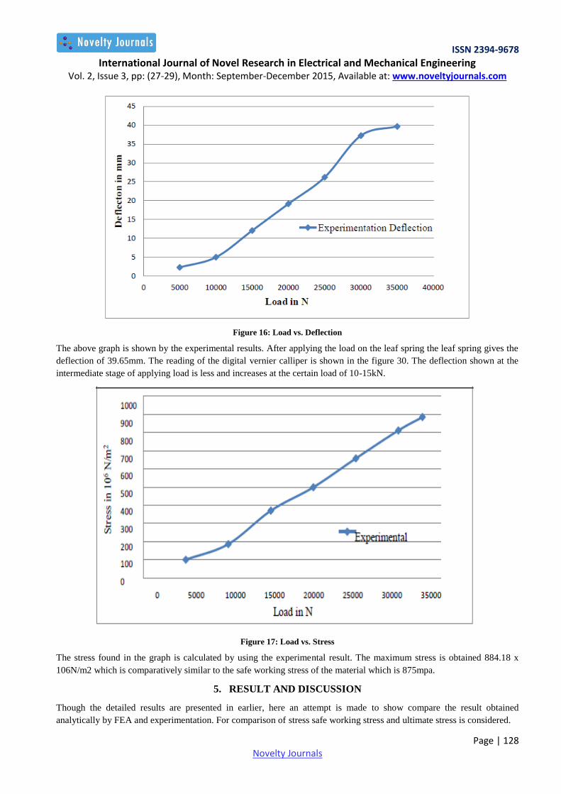
Table 6: Experimental Results for Deflection and Stress
Sr.no Load(N) Deflection(mm) Stress(N/m
2)
1 5000 2.3 100.64x10
06
2 10000 5 186.29x10
06
3 15000 12.07 369.94x10
06
4 20000 19.15 498.59x10
06
5 25000 26.190 657.24x10
06
6 30000 37.22 810.88x10
06
7 32833 39.65 884.18x10
06
ISSN 2394-9678
International Journal of Novel Research in Electrical and Mechanical Engineering Vol. 2, Issue 3, pp: (27-29), Month: September-December 2015, Available at: www.noveltyjournals.com
Page | 128 Novelty Journals
Figure 16: Load vs. Deflection
The above graph is shown by the experimental results. After applying the load on the leaf spring the leaf spring gives the
deflection of 39.65mm. The reading of the digital vernier calliper is shown in the figure 30. The deflection shown at the
intermediate stage of applying load is less and increases at the certain load of 10-15kN.
Figure 17: Load vs. Stress
The stress found in the graph is calculated by using the experimental result. The maximum stress is obtained 884.18 x
106N/m2 which is comparatively similar to the safe working stress of the material which is 875mpa.
5. RESULT AND DISCUSSION
Though the detailed results are presented in earlier, here an attempt is made to show compare the result obtained
analytically by FEA and experimentation. For comparison of stress safe working stress and ultimate stress is considered.

ISSN 2394-9678
International Journal of Novel Research in Electrical and Mechanical Engineering Vol. 2, Issue 3, pp: (27-29), Month: September-December 2015, Available at: www.noveltyjournals.com
Page | 129 Novelty Journals
Figure 18: Comparison of Simulation, Analytical and Experimental Deflection
The deflections are evaluated at various loads varying from 5000N to 32833N. The results are given in the above
tables and it is observed that the experimental deflection as compared to analytical and FEA deflection is less and
maximum deflection is shown by finite element analysis. The results shown by experimentation are near to the values of
the result shown by analytical and FEA. The deflection by simulation is 46.10, by analytical it is 44.68 and by
experimental 39.65mm. The below shown graph shows the stress value which is calculated by formula and
analytical methods are allowable values. The value obtained of von mises stress by using FEA is 1361.3mpa which is
less than the ultimate tensile stress of the material-1750mpa and the stress obtained by other methods is less than the
value of safe working stress. Safe working stress is calculated as 875mpa.
Figure 19: Comparison of Simulation, Analytical and Experimental Stress
5.1 Validation of Result:
Comparing the results by Hand calculation, FEA and Experimental shows that by hand calculation the stress is 710.70
x 106
which is similar to the safe stress of the given material is 875 x 106
. The deflection calculated by hand
calculation is 44.68 while that of FEA is 46.104, which shows that the deflection is similar to each other. The

ISSN 2394-9678
International Journal of Novel Research in Electrical and Mechanical Engineering Vol. 2, Issue 3, pp: (27-29), Month: September-December 2015, Available at: www.noveltyjournals.com
Page | 130 Novelty Journals
comparison in the graphs is shown above. The percentage variation of deflection considering FEA and hand calculation is
4%, FEA and experimental is 14%. The percentage variation of stress considering FEA and hand calculation is 12.35%
while that of FEA and experimental is 9%.
Table 7: Deflection and stress result
Methodology Deflection in mm Stress in N/m
2
Hand Calculation 44.68 710.70 x 10
6
FEA 46.104 810.77 x 10
6
Experimental 39.65 884.18 x 10
6
6. CONCLUSION
The automobile chassis is mounted on the axles in form of springs. This is done to isolate the vehicle body from the road
shocks which may be in the form of bounce, pitch, roll, etc. These tendencies give rise to an uncomfortable ride and also
cause additional stress in the automobile frame and body. All the part which performs the function of isolating the
automobile from the road shocks are collectively called a suspension system.
Leaf spring is a device which is used in suspension system to safeguard the vehicle and the occupants. For safe and
comfortable riding i.e, to prevent the road shocks from being transmitted to the vehicle components and to safeguard the
occupants from road shocks it is necessary to determine the maximum safe stress and deflection. Therefore in the present
work, leaf spring is designed by using 32833N load. By considering this load the leaf spring is designed , modelling of
leaf spring is created using CATIA V5 and analysis is done using ANSYS 14.5 workbench and it is concluded that for the
given specifications of the leaf spring, the stress is found below its safe working stress of material which is used for the
leaf spring. And 1361.3mpa von mises stress is also below its ultimate tensile stress. The deflection found by using all
methods is nearly same and the maximum deflection is 46.10mm.
REFERENCES
[1] G Harinath Gowd, E Venugopal Goud “Static Analysis of leaf spring” International Journal of Engineering Science
and Technology (IJEST), Volume-4, Issue-8August 2012, PP:3794-3803, ISSN No.:0975-5462.
[2] B.Mahesh Babu , D.Muralidhar Yadav, N.Ramanaiah “Leaf Spring Analysis with Eyes Using FEA” International
Journal of Computational Engineering Research, Volume-3, Issue-10Octomber 2013, PP:13-17, ISSN No.: 2250-
3005.
[3] Y. Venu, G. Diwakar “Static and Modal Analysis of Leaf Spring with Eyes Using FEA Packages” International
Journal of Engineering Research and Development, Volume-7, Issue-3May 2013, PP:71-77, ISSN No.(e-
ISSN:2278-067X,p-ISSN:2278-800X)
[4] Prof. N.P.Dhoshi, Prof .N.K.Ingole, Prof .U.D.Gulhane “Analysis and Modification of Leaf Spring of Tractor Trailer
Using Analytical and Finite Element Method” International Journal of Modern Engineering Research
(IJMER),Volume-1, Issue-2, PP:719-722, ISSN NO.:2249-6645.
[5] R. B. Charde , Dr. D.V. Bhope, “Investigation of Stresses In Masterleaf of Leaf Spring By Fem And Its
Experimental Verification” International Journal of Engineering Science and Technology (IJEST), Volume-4, Issue-
2February 2012, PP: 633-640, ISSN No.:0975-5462.
[6] Mr. V. K. Aher , Mr. P. M. Sonawane “Static And Fatigue Analysis Of Multi Leaf Spring Used In The Suspension
System Of LCV” International Journal of Engineering Research and Applications (IJERA), Volume-2, Issue-4 July-
August 2012, PP:.1786-1791, ISSN No.:2248-9622.
[7] By Harish V. Katore, Prof. Santosh B. Jaju “Redesigning Of Tractor Trolley Axle Using Ansys” International
Journal of Engineering Science and Technology (IJEST), Volume-3, Issue-6 June 2011,PP:4702-4710, ISSN
No.:0975-5462.

ISSN 2394-9678
International Journal of Novel Research in Electrical and Mechanical Engineering Vol. 2, Issue 3, pp: (27-29), Month: September-December 2015, Available at: www.noveltyjournals.com
Page | 131 Novelty Journals
[8] Happy Bansal1, Sunil Kumar “Weight Reduction and Analysis of Trolley Axle Using Ansys” International Journal
of Engineering and Management Research, Volume-2, Issue-6December 2012, PP:32-36, ISSN No.:2250-0758.
[9] Kumar Krishan and Aggarwal M.L. “A Finite Element Approach for Analysis of a Multi Leaf Spring using CAE
Tools” Research Journal of Recent Sciences, Volume- 1(2), Issue-30January 2012,PP:92-96, ISSN No.:2277-2502.
[10] Ritesh Kumar Dewangan, Manas Patnaik, Narendra Yadav “Minimization Of Stress Of A Parabolic Leaf Spring By
Simulated Annealing Algorithm” International Journaal of Engineering Research and Applications
(IJERA),Volume-2, Issue 4Jully-August 2012, PP:457-460, ISSN No.: 2248-9622.
[11] M. M. Patunkar, D. R. Dolas “Modelling and Analysis of Composite Leaf Spring under the Static Load Condition by
using FEA” International Journal of Mechanical and Industrial Engineering, volume-1, Issue- January2011.