Design and Analysis and optimisation of vehicle B-pillar
26
DESIGN AND ANALYSIS AND OPTIMISATION OF VEHICLE B-PILLAR MODULE LEADER- MARTIN LANDER REPORT SUBMITTED BY IMRAN SHIHABUDEEN RAJELA 5914621
-
Upload
imran-shihabudeen-rajela -
Category
Documents
-
view
211 -
download
3
Transcript of Design and Analysis and optimisation of vehicle B-pillar
DESIGN AND ANALYSIS AND OPTIMISATION OF VEHICLE
B-PILLAR
MODULE LEADER- MARTIN LANDER
REPORT SUBMITTED BY
IMRAN SHIHABUDEEN RAJELA
5914621
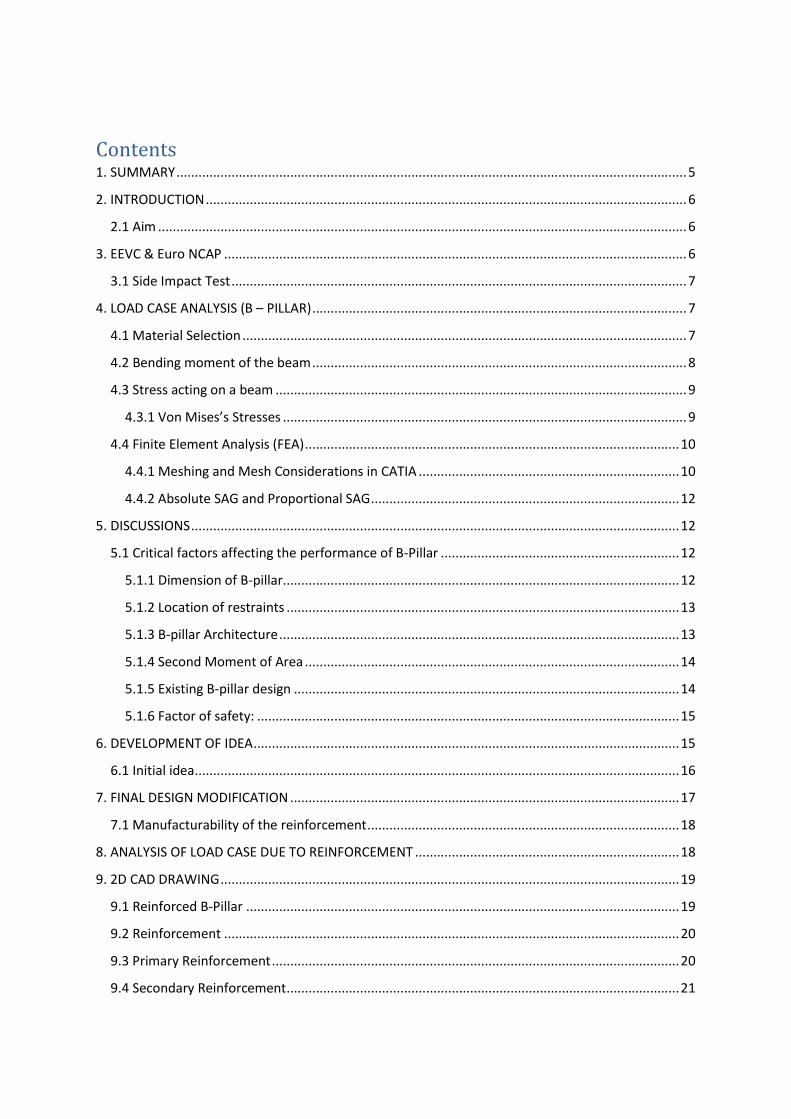
Contents 1. SUMMARY ........................................................................................................................................... 5
2. INTRODUCTION ................................................................................................................................... 6
2.1 Aim ................................................................................................................................................ 6
3. EEVC & Euro NCAP .............................................................................................................................. 6
3.1 Side Impact Test ............................................................................................................................ 7
4. LOAD CASE ANALYSIS (B – PILLAR) ...................................................................................................... 7
4.1 Material Selection ......................................................................................................................... 7
4.2 Bending moment of the beam ...................................................................................................... 8
4.3 Stress acting on a beam ................................................................................................................ 9
4.3.1 Von Mises’s Stresses .............................................................................................................. 9
4.4 Finite Element Analysis (FEA) ...................................................................................................... 10
4.4.1 Meshing and Mesh Considerations in CATIA ....................................................................... 10
4.4.2 Absolute SAG and Proportional SAG .................................................................................... 12
5. DISCUSSIONS ..................................................................................................................................... 12
5.1 Critical factors affecting the performance of B-Pillar ................................................................. 12
5.1.1 Dimension of B-pillar ............................................................................................................ 12
5.1.2 Location of restraints ........................................................................................................... 13
5.1.3 B-pillar Architecture ............................................................................................................. 13
5.1.4 Second Moment of Area ...................................................................................................... 14
5.1.5 Existing B-pillar design ......................................................................................................... 14
5.1.6 Factor of safety: ................................................................................................................... 15
6. DEVELOPMENT OF IDEA .................................................................................................................... 15
6.1 Initial idea .................................................................................................................................... 16
7. FINAL DESIGN MODIFICATION .......................................................................................................... 17
7.1 Manufacturability of the reinforcement ..................................................................................... 18
8. ANALYSIS OF LOAD CASE DUE TO REINFORCEMENT ........................................................................ 18
9. 2D CAD DRAWING ............................................................................................................................. 19
9.1 Reinforced B-Pillar ...................................................................................................................... 19
9.2 Reinforcement ............................................................................................................................ 20
9.3 Primary Reinforcement ............................................................................................................... 20
9.4 Secondary Reinforcement ........................................................................................................... 21

9.5 Exploded View ............................................................................................................................. 22
10. CONCLUSION AND RECOMMENDATION......................................................................................... 22
10.1 Conclusions ............................................................................................................................... 22
10.2 Recommendations .................................................................................................................... 22
10. 3 Limitations of FEA solver .......................................................................................................... 23
11. REFERENCE ...................................................................................................................................... 23
12. APPENDIX ........................................................................................................................................ 24
Catia Report Generation: ..................................................................... Error! Bookmark not defined.
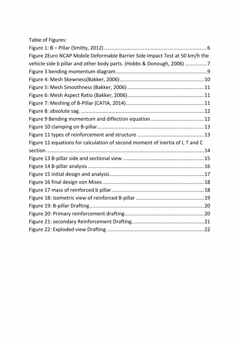
Table of Figures:
Figure 1: B – Pillar (Smitty, 2012) ....................................................................... 6
Figure 2Euro NCAP Mobile Deformable Barrier Side Impact Test at 50 km/h the
vehicle side b pillar and other body parts. (Hobbs & Donough, 2006) ............... 7
Figure 3 bending momentum diagram ............................................................... 9
Figure 4: Mesh Skewness(Bakker, 2006) .......................................................... 10
Figure 5: Mesh Smoothness (Bakker, 2006) ..................................................... 11
Figure 6: Mesh Aspect Ratio (Bakker, 2006) ..................................................... 11
Figure 7: Meshing of B-Pillar (CATIA, 2014) ...................................................... 11
Figure 8: absolute sag. ..................................................................................... 12
Figure 9 Bending momentum and diflection equation ..................................... 12
Figure 10 clamping on B-pillar .......................................................................... 13
Figure 11 types of reinforcement and structure .............................................. 13
Figure 12 equations for calculation of second moment of inertia of I, T and C
section ............................................................................................................. 14
Figure 13 B-pillar side and sectional view ........................................................ 15
Figure 14 B-pillar analysis ................................................................................ 16
Figure 15 initial design and analysis ................................................................. 17
Figure 16 final design von Mises ...................................................................... 18
Figure 17 mass of reinforced b pillar ................................................................ 18
Figure 18: Isometric view of reinforced B-pillar ............................................... 19
Figure 19: B-pillar Drafting ............................................................................... 20
Figure 20: Primary reinforcement drafting....................................................... 20
Figure 21: secondary Reinforcement Drafting .................................................. 21
Figure 22: Exploded view Drafting ................................................................... 22
1. SUMMARY
This technical report is the representation of the study carried out on a car B–pillar for optimising it
under the given condition by performing a load case analysis on the component using an FEA solver.
It also represents my knowledge in surface designing along with my knowledge in finite element
analysis. The given design is modified without changing its basic outer structure to bring it optimised
under the given load case, with a desirable deformation under the required mass limit. The design is
generated under the consideration of real time business scenarios such as, material, mass,
manufacturability and time. The impact of reinforcement, types of reinforcements, effect of change
in geometry and material properties of reinforcement are also discoursed in this work. A detail
description of the software used and the steps followed to generating the design and for analysing is
also explained in this work. The report discourse the stages in developing idea and modifications
made to get an optimised result. The 2-D CAD drawings of the final design are drawn considering
BS8888 to give the clarity of design. The limitation of FEA solver and the assumption made for the
analysis process are also discussed in the report for future development.
2. INTRODUCTION
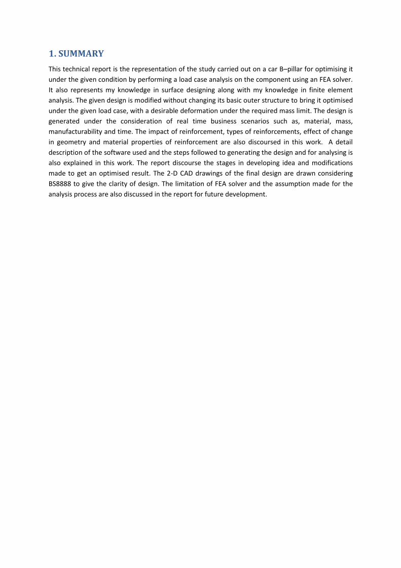
A B–pillar is a structure that is seen on the two sides of the car, which is held by the roof rail and the
bottom rail of a vehicle frame. It acts as a rigid support for the body frame to resist the forces acting
on the vehicle due to side impact and in case of roll-over of the vehicle. The B-pillar is provided with
reinforcement to reduce the deformation due to side impact force. The optimal design of the
reinforcement is made by the consideration of deformation limit, thickness of material used and the
load subjected on it. It should be lighter and also should absorb the impact load with lesser
deformation. Many research studies are still going on in the development of b pillar, to improve its
performance by limiting the material, weight and cost of production with an ease of manufacturing
at a lesser time. A typical B–pillar is as seen in the image below.
Figure 1: B – Pillar (Smitty, 2012)
2.1 Aim The primary aim of this report work is to demonstrate my knowledge about vehicle structures,
surfacing using parameters, and different tool in CATIA and re-design the B-pillar with a
reinforcement which is optimised with-in the design parameters, structural constraints, and mass
constraint provided by the Euro NCAP and FMVSS for the structural safety of a new car. The new
vehicle standards of Euro NCAP state that the roof of the vehicle should support twice the load of
the vehicle without occupant. Also, the B-pillar should be under the elastic limit and should not
exceed a maximum deformation rang of above 40mm; considering the weight to be a major vehicle
performance factor.
3. EEVC & Euro NCAP
European Enhanced Vehicle safety Committee (EEVC) is an organisation that assigns the safety
limits of the vehicle and its components. It is been developed for the passive safety of the vehicle
occupant. An artificial collision testing environment is created for analysing the safety limits of the
vehicle. The vehicle body is fitted with several accelerometer sensors is used to determine the
impact strength and the deformation caused by that impact on the vehicle structure. Without the
approval of the EECV, the car body design is not considered safer for the real time accidents.
European new car assessment programme (Euro NCAP) is developed to provide a fair, meaningful
and objective assessment for the safety performance of cars. It is indented to inform consumers, as
well as the manufacturers about the safety performance of their car and giving credit to those who
provide maximum protection. The impact tests are based on those developed for legislation by the
European Enhanced Vehicle safety Committee (EEVC) for frontal and side impact protection of car
occupants.
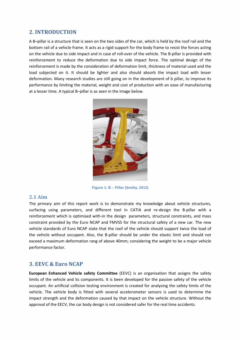
3.1 Side Impact Test It is the test carried out by the Euro NCAP to determine the safety credentials of a vehicle when
subjected to a side impact load. The impact test is carried out is of two type; pole side impact test
and barrier side impact test. In the test the car is impacted on the driver’s door side by a 950 kg
Mobile Deformable Barrier (MDB), at 50 km/h. This test is used to determine the impact strength
and deformation caused on t
Figure 2: Euro NCAP Mobile Deformable Barrier Side Impact Test at 50 km/h the vehicle side b pillar and other body parts. (Hobbs & Donough, 2006)
4. LOAD CASE ANALYSIS (B – PILLAR)
For the optimisation of B-pillar, it was necessary to understand the load case, structural and material
properties and its limitations. For this a detailed study of the vehicle B-pillar is carried out to analyse
presently used methodologies in selecting materials for the B pillar and reinforcement,
reinforcement types, structures, manufacturability, time consumption cost effectiveness etc.
4.1 Material Selection Performance relays as the major factor on designing a product, structural stability at a lesser weight
with easy to manufacture is given more priority than simply concentrating on the basic requirement.
For the B-pillar, light weight structure with higher strength and lesser material and fewer welds will
be more desirable for the easy manufacturing. High Strength steel is structurally rigid, and is flexible
under elastic limit. It is cheaper and easy to cut join and weld.
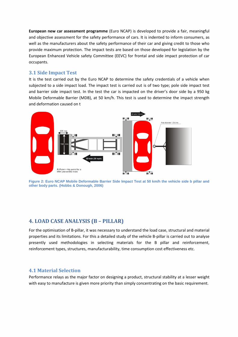
For B pillar the material assigned was CP Steel 800/1000. The maximum allowable thickness was of
about 1.4 mm. And for reinforcement the material selected was High Alloy Steel. And maximum
allowable thickness was about 2 mm
Components
Maximum Thickness (mm)
Material
De
nsi
ty
(kg/
m3 )
Yo
un
g's
Mo
du
lus
(GP
a)
Yie
ld
Stre
ngt
h
(MP
a)
Ten
sile
stre
ngt
h
(MP
a)
Po
isso
n's
rati
o
B-pillar 1.4 CP Steel 800/1000
7850 210 800 1000 0.3
Reinforcements 2.0 High Alloy Steel
7850 210 1500 1700 0.3
Table : geometrical Constrains and Physical Properties
Load acting on sides of B-pillar = 140 kN
Maximum deformation of B-pillar = 40 mm
Combined mass of B-pillar and reinforcement = < 6kgs
Material under elastic limit
For the initial analysis, the B-pillar is considered as rigidly supported beam with a uniformly
distributed load. The assumption of uniformly distributed load is considered for the ease of hand
calculation.
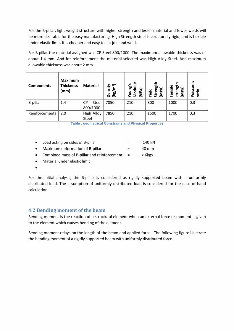
4.2 Bending moment of the beam Bending moment is the reaction of a structural element when an external force or moment is given
to the element which causes bending of the element.
Bending moment relays on the length of the beam and applied force. The following figure illustrate
the bending moment of a rigidly supported beam with uniformly distributed force.
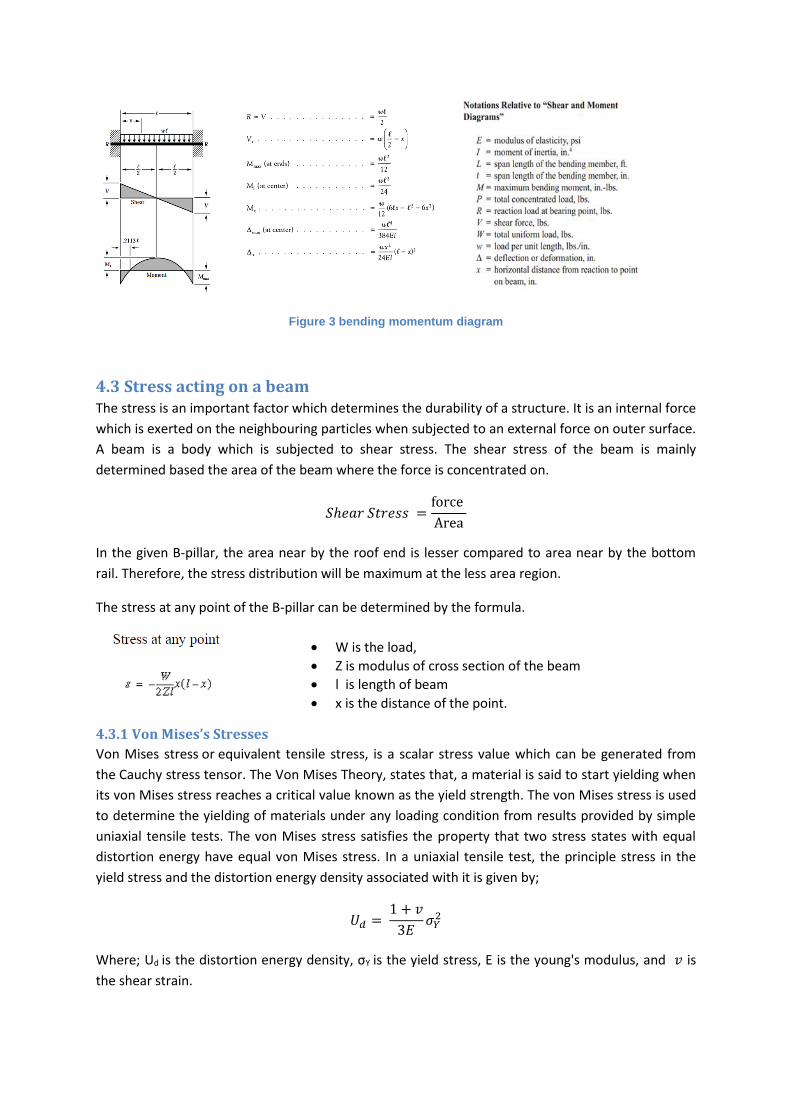
Figure 3 bending momentum diagram
4.3 Stress acting on a beam The stress is an important factor which determines the durability of a structure. It is an internal force
which is exerted on the neighbouring particles when subjected to an external force on outer surface.
A beam is a body which is subjected to shear stress. The shear stress of the beam is mainly
determined based the area of the beam where the force is concentrated on.
𝑆ℎ𝑒𝑎𝑟 𝑆𝑡𝑟𝑒𝑠𝑠 =force
Area
In the given B-pillar, the area near by the roof end is lesser compared to area near by the bottom
rail. Therefore, the stress distribution will be maximum at the less area region.
The stress at any point of the B-pillar can be determined by the formula.
4.3.1 Von Mises’s Stresses
Von Mises stress or equivalent tensile stress, is a scalar stress value which can be generated from
the Cauchy stress tensor. The Von Mises Theory, states that, a material is said to start yielding when
its von Mises stress reaches a critical value known as the yield strength. The von Mises stress is used
to determine the yielding of materials under any loading condition from results provided by simple
uniaxial tensile tests. The von Mises stress satisfies the property that two stress states with equal
distortion energy have equal von Mises stress. In a uniaxial tensile test, the principle stress in the
yield stress and the distortion energy density associated with it is given by;
𝑈𝑑 = 1 + 𝑣
3𝐸𝜎𝑌
2
Where; Ud is the distortion energy density, σY is the yield stress, E is the young's modulus, and 𝑣 is
the shear strain.
W is the load,
Z is modulus of cross section of the beam
l is length of beam
x is the distance of the point.
4.4 Finite Element Analysis (FEA) FEA is the mathematical method used to analyse the properties of a substance. It generate a
matrixes of finite number of elements and a splits the applied components to finite no of small areas
the applied properties to the materials are thus subjected to all these areas with continuous
reference. The advantage of FEA is that, it can provide the details of material property at any point
of material. It used finite number of nodes and elements to generate meshes to form uniform area
and compute the results for each of those unit areas.
4.4.1 Meshing and Mesh Considerations in CATIA
Meshing are the connections made between each nodes to form elements. The meshing splits the
entire area of the material to a number of unit areas. These areas are subjected to the applied
properties. Meshing varies based on the shape and structure of the material. For surface, 2D
meshing is used; whereas for SOLID, 3D meshing properties are used. In CATIA 2D meshing is done
using ‘OCTREE Triangle Mesher' and for 3D 'OCTREE tetrahedron Mesher' is used.
There are various mesh cell types that are used in FEA. The commonly used mesh types are;
Tri mesh – mesh between nodes form elements of closed triangular structure.
Quad mesh – mesh between nodes to form elements of closed rectangular structure.
Hex mesh – mesh between nodes to form elements of closed hexahedral structure.
Another factor to be considered while meshing is the mesh quality. There are three kinds of mesh
quality, these are;
Skewness
Smoothness
Aspect Ratio
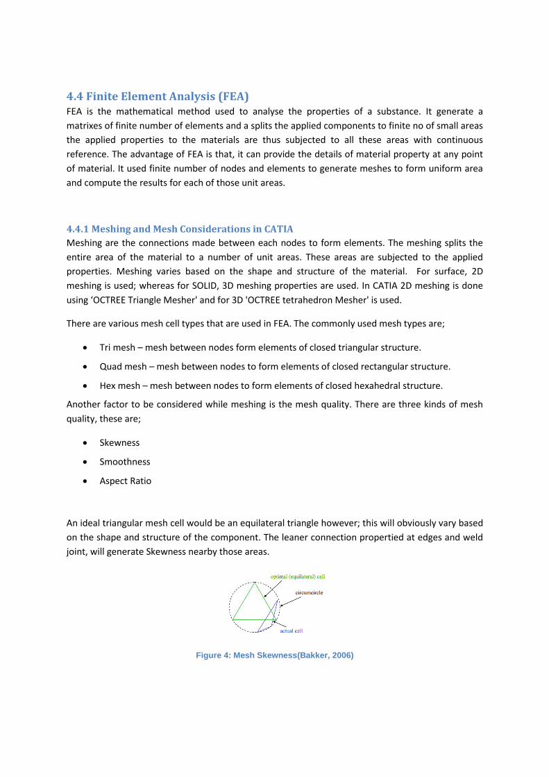
An ideal triangular mesh cell would be an equilateral triangle however; this will obviously vary based
on the shape and structure of the component. The leaner connection propertied at edges and weld
joint, will generate Skewness nearby those areas.
Figure 4: Mesh Skewness(Bakker, 2006)
While meshing, generally the mesh formed will be uniform at the main surface and changes
gradually when moves to edges. Smoothness of meshing basically meant for the gradual change in
size of the mesh while approaching the limiting areas
Figure 5: Mesh Smoothness (Bakker, 2006)
All messes are assigned based on a particular aspect ratios. The aspect ratio provides ratio of the
longest edge length to that of the shortest edge length. In an ideal case it would be equal to 1. Based
on the aspect ratio the calculation time is determined. (For an equilateral triangle) (Bakker, 2006).
Figure 6: Mesh Aspect Ratio (Bakker, 2006)
While using generative structural analysis in CATIA, the meshing is generated using the ‘OCTREE
Triangle Mesher'. This is done because the B pillar and reinforcement designed is limited to analyse
using surfaces and thus it is considered as 2D bodies.
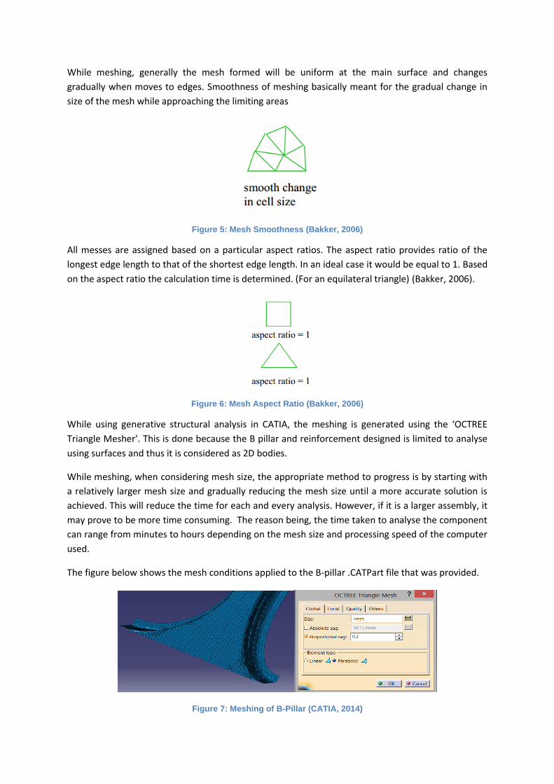
While meshing, when considering mesh size, the appropriate method to progress is by starting with
a relatively larger mesh size and gradually reducing the mesh size until a more accurate solution is
achieved. This will reduce the time for each and every analysis. However, if it is a larger assembly, it
may prove to be more time consuming. The reason being, the time taken to analyse the component
can range from minutes to hours depending on the mesh size and processing speed of the computer
used.
The figure below shows the mesh conditions applied to the B-pillar .CATPart file that was provided.
Figure 7: Meshing of B-Pillar (CATIA, 2014)
4.4.2 Absolute SAG and Proportional SAG
Absolute Sag is the maximum gap between the mesh and the geometry. It provide sag constraints
while meshing the edges.
Proportional Sag is the ratio between the local absolute sag and the local mesh edge length.
Absolut sag and proportional sag can modify the meshing’s at the edges.
Proportional sag value= (local Absolute sag value) / (local mesh edge length value)
Figure 8: absolute sag.
5. DISCUSSIONS
5.1 Critical factors affecting the performance of B-Pillar There are many factors which are responsible for the performance of B-Pillar. It is essential to
understand them deeply before assigning the design for reinforcement.
5.1.1 Dimension of B-pillar
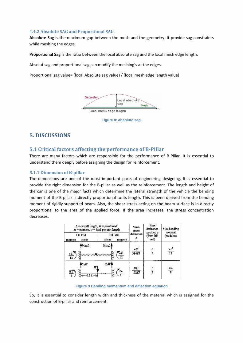
The dimensions are one of the most important parts of engineering designing. It is essential to
provide the right dimension for the B-pillar as well as the reinforcement. The length and height of
the car is one of the major facts which determine the lateral strength of the vehicle the bending
moment of the B pillar is directly proportional to its length. This is been derived from the bending
moment of rigidly supported beam. Also, the shear stress acting on the beam surface is in directly
proportional to the area of the applied force. If the area increases; the stress concentration
decreases.
Figure 9 Bending momentum and diflection equation
So, it is essential to consider length width and thickness of the material which is assigned for the
construction of B-pillar and reinforcement.
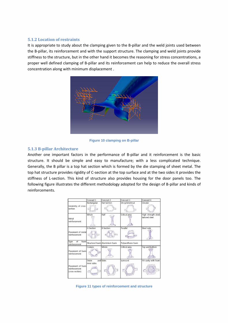
5.1.2 Location of restraints
It is appropriate to study about the clamping given to the B-pillar and the weld joints used between
the B-pillar, its reinforcement and with the support structure. The clamping and weld joints provide
stiffness to the structure, but in the other hand it becomes the reasoning for stress concentrations, a
proper well defined clamping of B-pillar and its reinforcement can help to reduce the overall stress
concentration along with minimum displacement .
Figure 10 clamping on B-pillar
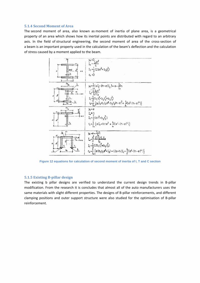
5.1.3 B-pillar Architecture
Another one important factors in the performance of B-pillar and it reinforcement is the basic
structure. It should be simple and easy to manufacture; with a less complicated technique.
Generally, the B pillar is a top hat section which is formed by the die stamping of sheet metal. The
top hat structure provides rigidity of C-section at the top surface and at the two sides it provides the
stiffness of L-section. This kind of structure also provides housing for the door panels too. The
following figure illustrates the different methodology adopted for the design of B-pillar and kinds of
reinforcements.
Figure 11 types of reinforcement and structure
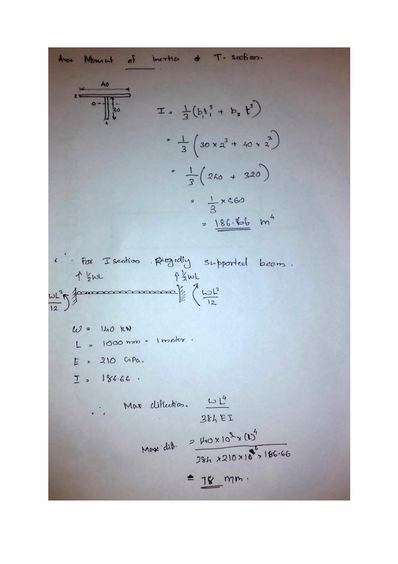
5.1.4 Second Moment of Area
The second moment of area, also known as moment of inertia of plane area, is a geometrical
property of an area which shows how its inertial points are distributed with regard to an arbitrary
axis. In the field of structural engineering, the second moment of area of the cross-section of
a beam is an important property used in the calculation of the beam's deflection and the calculation
of stress caused by a moment applied to the beam.
Figure 12 equations for calculation of second moment of inertia of I, T and C section
5.1.5 Existing B-pillar design
The existing b pillar designs are verified to understand the current design trends in B-pillar
modification. From the research it is concludes that almost all of the auto manufacturers uses the
same materials with slight different properties. The designs of B-pillar reinforcements, and different
clamping positions and outer support structure were also studied for the optimisation of B-pillar
reinforcement.
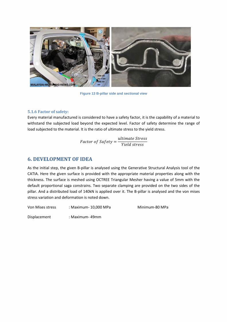
Figure 13 B-pillar side and sectional view
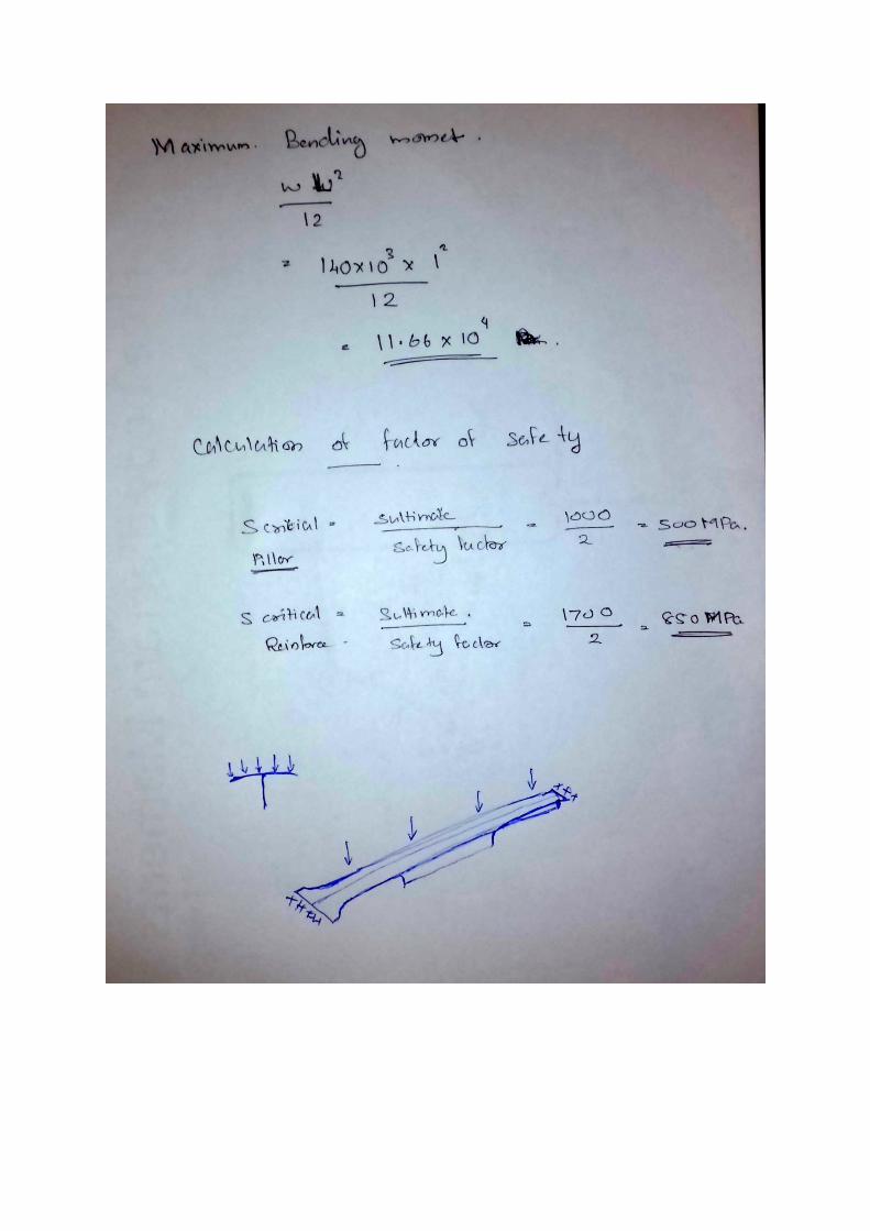
5.1.6 Factor of safety:
Every material manufactured is considered to have a safety factor, it is the capability of a material to
withstand the subjected load beyond the expected level. Factor of safety determine the range of
load subjected to the material. It is the ratio of ultimate stress to the yield stress.
𝐹𝑎𝑐𝑡𝑜𝑟 𝑜𝑓 𝑆𝑎𝑓𝑒𝑡𝑦 =𝑢𝑙𝑡𝑖𝑚𝑎𝑡𝑒 𝑆𝑡𝑟𝑒𝑠𝑠
𝑌𝑖𝑒𝑙𝑑 𝑠𝑡𝑟𝑒𝑠𝑠
6. DEVELOPMENT OF IDEA
As the initial step, the given B-pillar is analysed using the Generative Structural Analysis tool of the
CATIA. Here the given surface is provided with the appropriate material properties along with the
thickness. The surface is meshed using OCTREE Triangular Mesher having a value of 5mm with the
default proportional saga constrains. Two separate clamping are provided on the two sides of the
pillar. And a distributed load of 140kN is applied over it. The B-pillar is analysed and the von mises
stress variation and deformation is noted down.
Von Mises stress : Maximum- 10,000 MPa Minimum-80 MPa
Displacement : Maximum- 49mm
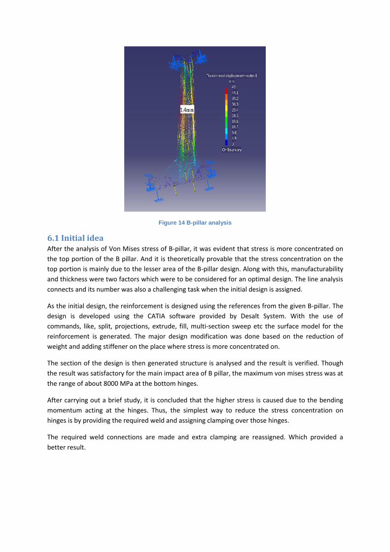
Figure 14 B-pillar analysis
6.1 Initial idea After the analysis of Von Mises stress of B-pillar, it was evident that stress is more concentrated on
the top portion of the B pillar. And it is theoretically provable that the stress concentration on the
top portion is mainly due to the lesser area of the B-pillar design. Along with this, manufacturability
and thickness were two factors which were to be considered for an optimal design. The line analysis
connects and its number was also a challenging task when the initial design is assigned.
As the initial design, the reinforcement is designed using the references from the given B-pillar. The
design is developed using the CATIA software provided by Desalt System. With the use of
commands, like, split, projections, extrude, fill, multi-section sweep etc the surface model for the
reinforcement is generated. The major design modification was done based on the reduction of
weight and adding stiffener on the place where stress is more concentrated on.
The section of the design is then generated structure is analysed and the result is verified. Though
the result was satisfactory for the main impact area of B pillar, the maximum von mises stress was at
the range of about 8000 MPa at the bottom hinges.
After carrying out a brief study, it is concluded that the higher stress is caused due to the bending
momentum acting at the hinges. Thus, the simplest way to reduce the stress concentration on
hinges is by providing the required weld and assigning clamping over those hinges.
The required weld connections are made and extra clamping are reassigned. Which provided a
better result.
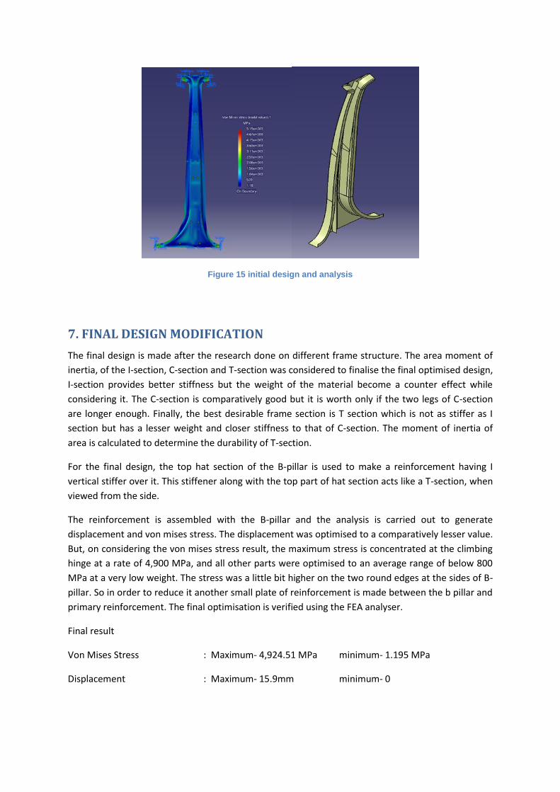
Figure 15 initial design and analysis
7. FINAL DESIGN MODIFICATION
The final design is made after the research done on different frame structure. The area moment of
inertia, of the I-section, C-section and T-section was considered to finalise the final optimised design,
I-section provides better stiffness but the weight of the material become a counter effect while
considering it. The C-section is comparatively good but it is worth only if the two legs of C-section
are longer enough. Finally, the best desirable frame section is T section which is not as stiffer as I
section but has a lesser weight and closer stiffness to that of C-section. The moment of inertia of
area is calculated to determine the durability of T-section.
For the final design, the top hat section of the B-pillar is used to make a reinforcement having I
vertical stiffer over it. This stiffener along with the top part of hat section acts like a T-section, when
viewed from the side.
The reinforcement is assembled with the B-pillar and the analysis is carried out to generate
displacement and von mises stress. The displacement was optimised to a comparatively lesser value.
But, on considering the von mises stress result, the maximum stress is concentrated at the climbing
hinge at a rate of 4,900 MPa, and all other parts were optimised to an average range of below 800
MPa at a very low weight. The stress was a little bit higher on the two round edges at the sides of B-
pillar. So in order to reduce it another small plate of reinforcement is made between the b pillar and
primary reinforcement. The final optimisation is verified using the FEA analyser.
Final result
Von Mises Stress : Maximum- 4,924.51 MPa minimum- 1.195 MPa
Displacement : Maximum- 15.9mm minimum- 0
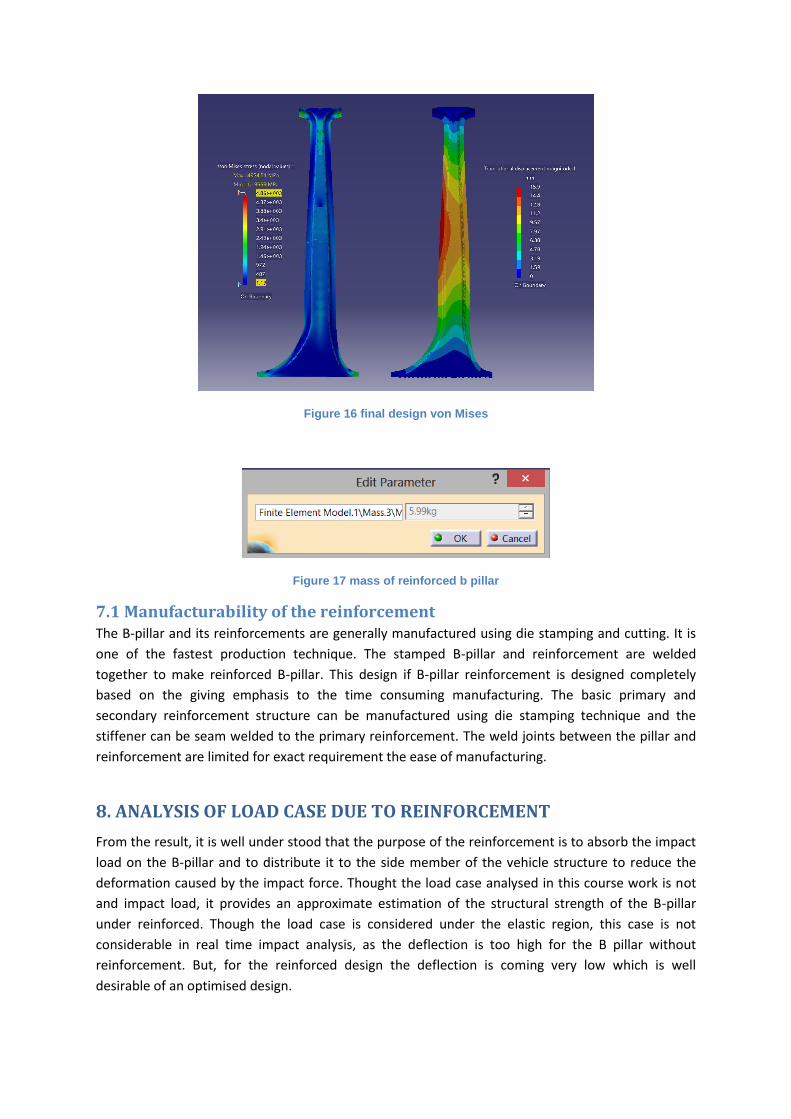
Figure 16 final design von Mises
Figure 17 mass of reinforced b pillar
7.1 Manufacturability of the reinforcement The B-pillar and its reinforcements are generally manufactured using die stamping and cutting. It is
one of the fastest production technique. The stamped B-pillar and reinforcement are welded
together to make reinforced B-pillar. This design if B-pillar reinforcement is designed completely
based on the giving emphasis to the time consuming manufacturing. The basic primary and
secondary reinforcement structure can be manufactured using die stamping technique and the
stiffener can be seam welded to the primary reinforcement. The weld joints between the pillar and
reinforcement are limited for exact requirement the ease of manufacturing.
8. ANALYSIS OF LOAD CASE DUE TO REINFORCEMENT
From the result, it is well under stood that the purpose of the reinforcement is to absorb the impact
load on the B-pillar and to distribute it to the side member of the vehicle structure to reduce the
deformation caused by the impact force. Thought the load case analysed in this course work is not
and impact load, it provides an approximate estimation of the structural strength of the B-pillar
under reinforced. Though the load case is considered under the elastic region, this case is not
considerable in real time impact analysis, as the deflection is too high for the B pillar without
reinforcement. But, for the reinforced design the deflection is coming very low which is well
desirable of an optimised design.
Without the reinforcement the von mises stress was too high, and was mainly concentrating on the
clamps. This is caused due to the bending moment acting at the clamps. Since the clamps are rigid
support, the displacement near by the clamps will be too low. Thus for the given load case, the
bending moment acting at that point will be too high. And, if the deflection is less, the stress which is
indirectly proportional to deflection, increases.
The maximum stress acting on the hinges can be either distributed to the reinforcement by giving
weld joints or by increasing the surface area of the reinforcement and clamping it.
9. 2D CAD DRAWING
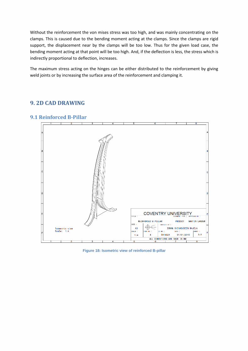
9.1 Reinforced B-Pillar
Figure 18: Isometric view of reinforced B-pillar
9.2 Reinforcement
Figure 19: B-pillar Drafting
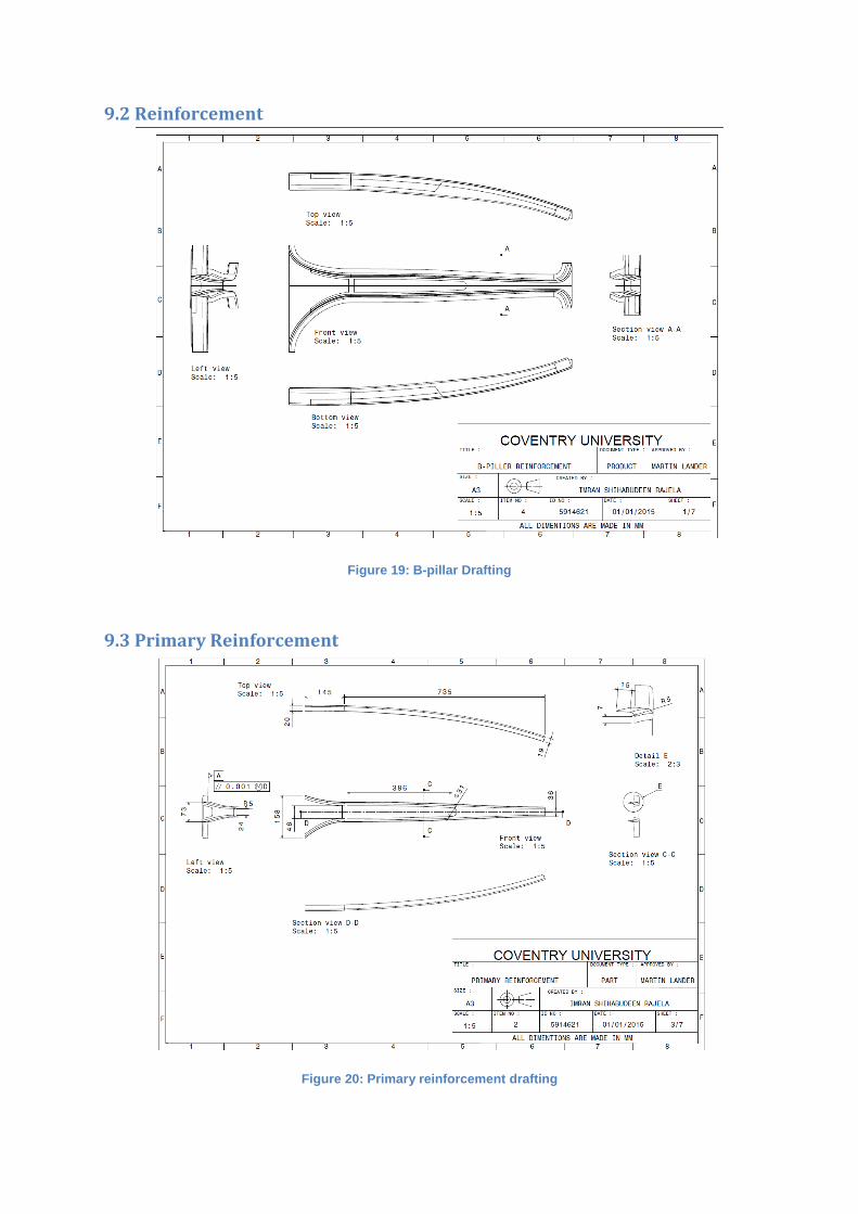
9.3 Primary Reinforcement
Figure 20: Primary reinforcement drafting
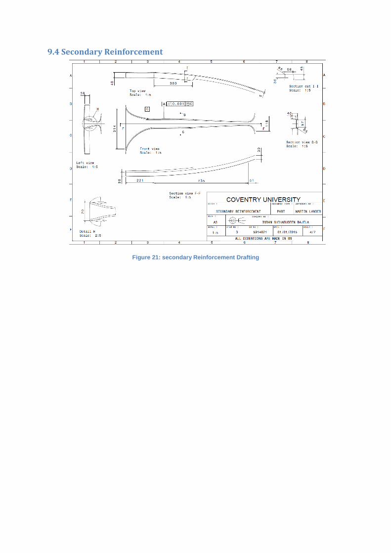
9.4 Secondary Reinforcement
Figure 21: secondary Reinforcement Drafting
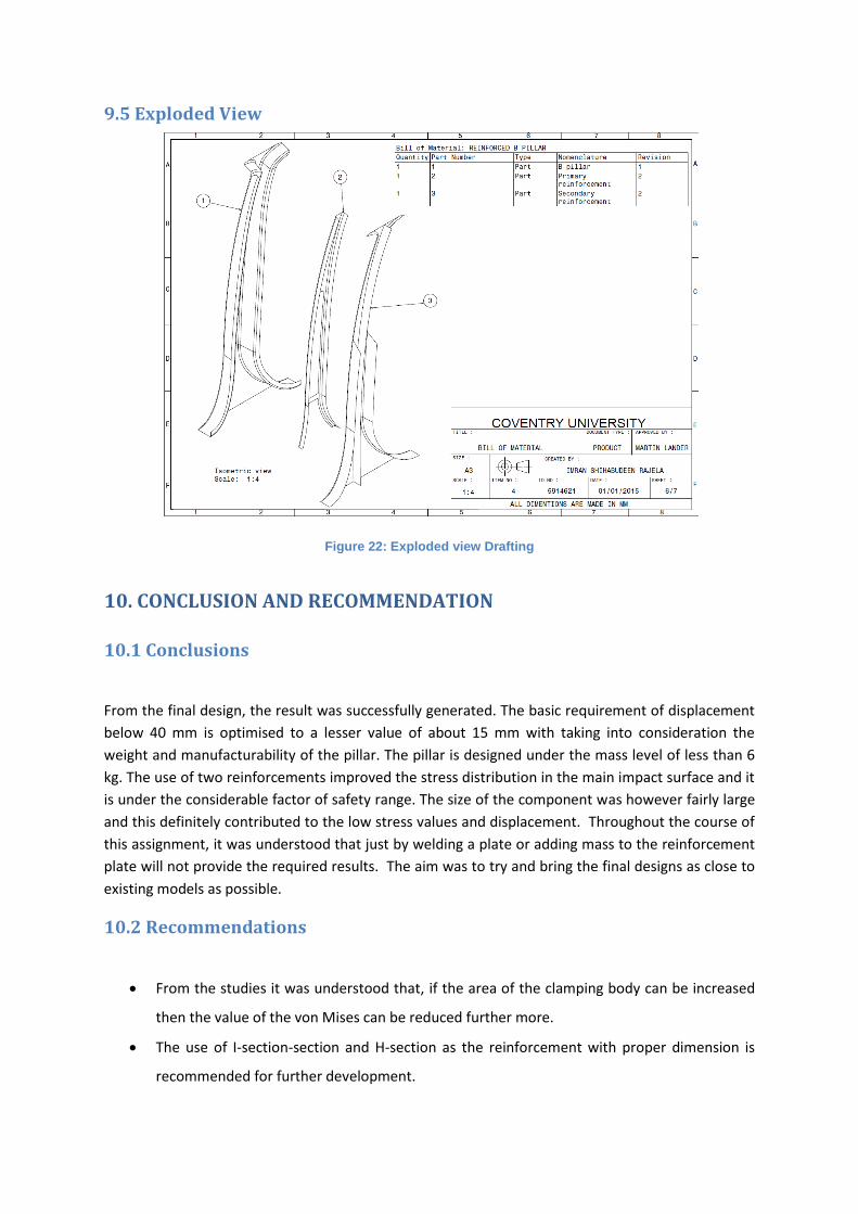
9.5 Exploded View
Figure 22: Exploded view Drafting
10. CONCLUSION AND RECOMMENDATION
10.1 Conclusions
From the final design, the result was successfully generated. The basic requirement of displacement
below 40 mm is optimised to a lesser value of about 15 mm with taking into consideration the
weight and manufacturability of the pillar. The pillar is designed under the mass level of less than 6
kg. The use of two reinforcements improved the stress distribution in the main impact surface and it
is under the considerable factor of safety range. The size of the component was however fairly large
and this definitely contributed to the low stress values and displacement. Throughout the course of
this assignment, it was understood that just by welding a plate or adding mass to the reinforcement
plate will not provide the required results. The aim was to try and bring the final designs as close to
existing models as possible.
10.2 Recommendations
From the studies it was understood that, if the area of the clamping body can be increased
then the value of the von Mises can be reduced further more.
The use of I-section-section and H-section as the reinforcement with proper dimension is
recommended for further development.
The addition of adhesives or foam between plates and B-pillar will also help to improve the
crash performance with a lesser weight.
The beads can also be used in the appropriate portions of the design to reduce the stress
concentration.
10. 3 Limitations of FEA solver
Meshing become a time consuming factor when the design get complicated and mesh size is
higher.
Line analysis connections are difficult to perform, and weld joint error are hard to identify.
Error citation is difficult in CATIA.
Stress concentration at very small area is hardly not been cited it the von mises colour
graph.
11. REFERENCE
Anderson, T. L. (2006). Fracture Mechanics - Fundamental and Applications (3rd ed.). Florida: CRC
Press.
Bakker, A. (2006). Computational Fluid Dynamics. Retrieved 1 11, 2013, from
http://www.bakker.org/dartmouth06/engs150/07-mesh.pdf
CATIA. (2014). Screenshots. Coventry: Dassualt Systemes.
Hobbs, C. A., & Donough, P. J. (2006). Development of the Europen New Car Assessment Programme
(Euro NCAP). United Kingdom: Transport Research Laboratory.
Smitty. (2012). Fire EMS Blogs. Retrieved 01 10, 2014, from
http://boronextrication.com/2011/12/2012-mercedes-benz-m-class-body-structure/
12. APPENDIX
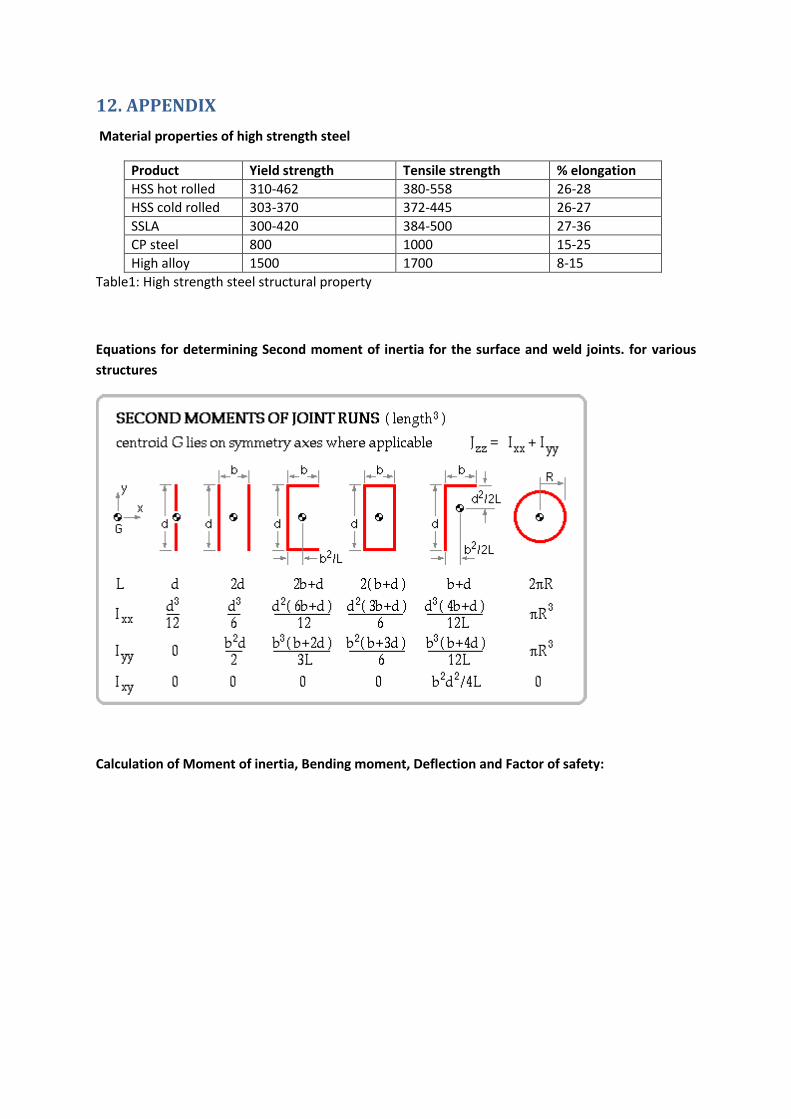
Material properties of high strength steel
Product Yield strength Tensile strength % elongation
HSS hot rolled 310-462 380-558 26-28
HSS cold rolled 303-370 372-445 26-27
SSLA 300-420 384-500 27-36
CP steel 800 1000 15-25
High alloy 1500 1700 8-15
Table1: High strength steel structural property
Equations for determining Second moment of inertia for the surface and weld joints. for various
structures
Calculation of Moment of inertia, Bending moment, Deflection and Factor of safety: