DESIGN AND ANALYSIS A NEW SPOILER FOR UMP REV USING …
24
DESIGN AND ANALYSIS A NEW SPOILER FOR UMP REV USING CFD MUHAMMAD NAJMUDIN BIN MOHD TAIB A report is submitted in partial fulfillment of the requirements for the award of the degree of Bachelor of Mechanical Engineering Faculty of Mechanical Engineering Universiti Malaysia Pahang. - - NOVEMBER 2007 :i
Transcript of DESIGN AND ANALYSIS A NEW SPOILER FOR UMP REV USING …

DESIGN AND ANALYSIS A NEW SPOILER FOR UMP REV USING CFD
MUHAMMAD NAJMUDIN BIN MOHD TAIB
A report is submitted in partial fulfillment
of the requirements for the award of the degree of
Bachelor of Mechanical Engineering
Faculty of Mechanical Engineering
Universiti Malaysia Pahang. - -
NOVEMBER 2007
:i

ABSTRACT
This thesis presents the design and develops new rear spoilers to overcome a
drag force that is created because of low pressure zone at the rear hack. With the new
design of rear spoiler for the Proton iswara Hybrid Electrical Vehicle (BV) UMP,
the performance of the car had increased from the aspect of acceleration and also
from the aspect of handling of the car, the controlled speed of this research is from
80 km/hr to 110 km/hr. The design of rear spoiler is based on the type of the car
used, therefore aerodynamic shape of the body and the point of the rear spoiler is
important in this research. In this research 2 spoilers have been choosing that are
squareback and fastback rear spoilers. According to that reason, low pressure zone
will be annihilated slowly if one of the rear spoilers is put at the rear back of the car.
Refer to data testing obtained, using squareback spoiler will reduce more low
pressure zone than using fastback spoiler. Based on the analysis, the suitable place to
mount the rear spoiler is at the point where squareback spoiler is mounted and it
synchronized with the shape of the Proton Iswara HEy. It will give additional
information to the performance car researcher to continue on this research thoroughly
about the effect of spoiler on any HEY car and eventually to Malaysia's first HEV
race car. In the future, this factor will give benefit to the Malaysia car developer
especially HEY car developer.
vi

ABSTRAK
Tesis mi telah merekabentuk spoiler belakang barn bagi mengatasi masalah
kewujudan daya tarikan yang wujud di zon belakang kereta. Dengan adanya spoiler
belakang mi juga prestasi kereta Proton Iswara jenis Hybrid Electrical Vehicle
(HEV) UMP mi akan rneningkat dari segi kelajuan dan pemanduan semasa berada di
dalam kelajuan 80 km/sejjarn hingga 1110 krn!sejarn. Rekabentuk spoiler belakang mi
berpandukan jenis kereta dan faktor-faktor seperti bentuk yang aerodinamik dan
kedudukan spoiler belakang itu. Di dalam kajian mi dua buah spoiler belakang telah
dibentuk iaitu jenis 'squareback' dan jenis 'fastback'. Menurut kajian mi, dengan
kehadiran salah satu spoiler belakang mi masalah kewujudan zon tekanan tinggi di
belakang kereta dapat dikurangkan dengan banyaknya. Daripada data ujikaji barn
mi, dngan kehadiran spoiler jenis 'squareback' dapat mengurangkan zon tekanan
tinggi lebih banyak berbanding spoiler jenis 'fastback'. Berpandu kepada analisa,
kedudukan spoiler yang strategik adalah pada kedudukan spoiler jenis 'squareback'
berbanding spoiler jenis 'fastback'. mi adalah disebabkan rekabentuk kereta Proton
Iswara HEy yang sesuai dengan spoiler jenis 'squareback' mi. mi memberikan satu
isyarat kepada para pengkaji berkaitan prestasi kereta untuk nieneruskan kajian
dengan lebih mendalam terhadap kesan spoiler belakang pada kereta jenis HEY di
Malaysia seterusnya untuk kereta lumba jenis HEY keluaran Malaysia. Semoga pada
masa akan datang, faktor mi akan mendatangkan nilai yang mendalam terhadap
bidang kenderaan terutamanya j enis HEV.
vii

TABLE OF CONTENTS
CHAPTER
TITLE PAGE
SUPERVISOR DECLARATION
STUDENT DECLARATION
DEDICATION iv
ACKNOWLEDGEMENT v
ABSTRACT vi
ABSTRAK vii
TABLE OF CONTENTS vii
LIST OF FIGURES xi
LIST OF TABLES xiii
LIST OF SYMBOLS xiv
LIST OF APPENDICES xv
1
INTRODUCTION
1.1 Spoiler I
1.2 Problem Statement 3
1.3 Project Objectives 4
1.4 Project Scopes 4
2 LITERATURE REVIEW
2.1 Introduction 5
2.2 Aerodynamics 7
vi"

2.2.1 Definition 7
2.2.2 Classes of Aerodynamic Problem 7
2.2.3 The Dynamic of Airflow and 8 Its Effects on Automobiles
2.2.4 Automotive Aerodynamics 8
2.3 Flow Separation through a Road Vehicle 9
2.3.1 Introduction 9
2.3.2 Flow Separation Process 9
2.3.3 External Flow 10
2.3.4 Boundary Layer Development 12
2.3.5 Laminar & Turbulent Flows 13
2.3.6 Drag Coefficient 14
2.4 Pressure Difference 14
2.5 Rear Spoiler 15
2.5.1 Introduction 15
2.5.2 Effect of Rear Spoiler 16
2.6 Hybrid Electrical Vehicle (HEY) 18
2.6.1 Development of HEV 18
2.6.2 Types of HEV 19
2.6.3 Battery Requirements for HEY 20
2.7 Computational Fluid Dynamics (CFD) 23
2.7.1 Introduction of CFD 23
2.7.2 COSMOS Floworks (Introduction) 23
2.7.3 Computational Domain 24
2.7.4 Meshing 25
2.7.5 Analysis Type 26
3 METHODOLOGY
3.1 Introduction 28
3.2 Project Methodology 28
3.3 Verify the FYP title given with supervisor 31
3.4 Searching information for literature review 31
x

x
3.4.1 Book and magazine 31
3.4.2 Related journal 32
3.4.3 Internet source 32
3.4.4 Discuss with supervisor and lectures 32
3.5 Measure the dimension of HEV Proton Iswara 33
3.6 3D Solid Modeling 34
3.6.1 HEV Proton Iswara's Body 34
3D Solid Modeling
3.6.2 Rear Spoiler Design 35
3D Solid Modeling
3.7 Air Flow Analysis 37
3.7.1 Simulation Air Flow Analysis 37
3.8 Data Gathered from Results 38
RESULTS AND DISCUSSION
4.1 The Information Regarding 39
The Result Obtained
4.2 The Effect of Fastback and Squareback 40 Rear Spoiler on REV Proton Iswara
4.2.1 Results View atllOkmjhr 40
4.2.2 Data table and graph at 110 km/hr 43
4.2.2.1 Analyze for the Side View 43
4.2.2.2 Analyze for the Rear View 46
CONCLUSION
5.1 Conclusion 50
5.2 Recommendations for Future Works 51
REFFERENCES 53 APPENDIX 54
4
5

LIST OF FIGURES
FIGURE NO. TITLE PAGE
I.I. The Rear Spoiler I
1.2 Aerodynamic flow around the car 2
2.1 Overview diagram for Literature Review 6
2.2 Flow separation process 10
2.3 Boundary layer 11
2.4 Flow around a vehicle (schematic). 11
2.5 Flow through a plate 12
2.6 Velocity boundary layer development on a flat plate 13
2.8 Pressure Differences at Car 15
2.9 Fastback Rear Spoiler 15
2.10 Two-dimensional flap as simulation model 16 for a rear spoiler
2.11 Drag lift pollars for different rear 17 spoiler arrangements
2.12 Pressure increase at the rear of a vehicle due to 17 a rear spoiler
2.13 Isobars on a fastback, with and without spoiler 18
2.14 11EV Drives Train Examples. 20
2.15 Examples for battery configurations for different 20 EV and 11EV drive trains
xl

2.17 Power profile of a 1130 kg car onNEDC 22
2.20 External Flows on COSMOS Floworks 26
3.1 Flow chart of project methodology 30
3.2 Proton lswara full models with dimension 35
3.3 Squareback full model and dimension 36
3.4 Fastback full model and dimension 36
4.1 Car without spoiler (Side view) 40
4.2 Car with fastback rear spoiler (Side View) 40
4.3 Car with squareback rear spoiler (Side View) 41
4.4 Car without spoiler (Rear view) 41
4.5 Car with fastback rear spoiler (Rear View) 42
4.6 Car with squareback rear spoiler (Rear View) 42
4.10 Car without Spoiler vs. With Fastback Spoiler 44
4.11 Car without Spoiler vs. With Squareback Spoiler 45
4.12 Different Graph for car with and without Spoiler 45
4.16 Car without Spoiler vs. With Fastback Spoiler 47
4.17 Car without Spoiler vs. With Squareback Spoiler 48
4.18 Different Graph for car with and without Spoiler 48
xli

LIST OF TABLES
FIGURE NO. TITLE PAGE
2.7 Drag Coefficient for Different Bodies 14 (Cd,c = D/qk Subcritical Flow)
2.16 PNGV definition/requirements of batteries for HEy 21
2.18 Cell size for 200-300 V, 1 kW h power 22 assist HEV battery
2.19 HEV battery requirements 23
3.1 Proton Iswara Specifications from Proton 33 Sdn. Bhd. web
4.7 Car without Rear Spoiler 43
4.8 Car with Fastback Spoiler 43
4.9 Car with Squareback Spoiler 44
4.13 Car without Rear Spoiler 46
4.14 Car with Fastback Spoiler 47
4.15 Car with Squareback Spoiler 47
xlii

LIST OF SYMBOLS
Cd Drag Coefficient
V Velocity
Re Reynold Number
V Viscosity
Shear Stress
U Gradient
'rs Surface Shear Stress
FD Surface Drag Force
S Cross Sectional Area
w Watt
V Volt
xiv

LIST OF APPENDICES
APPENDIX TITLE
PAGE
A Solid Work design 54
B Results from the simulation 60
C Point Parameters 62
xv

CHAPTER 1
INTRODUCTION
1.1 Spoiler
A spoiler is an aerodynamic device attached to an automobile whose intended
design function is to 'spoil' unfavorable air movement across a body , of a car in
motion. This can result in improved vehicle stability by decreasing lift or decreasing
drag that may cause unpredictable handling-in a-car at high speed. Spoilers are often
fitted to race and high-performance sports cars, although they have become common
on passenger vehicles, as well. Some spoilers are added to cars primarily for styling
purposes and have either :littie ae'rodyhimi& ,'bene'fiti or even make the aerodynamics,
worse.
Figure 1.1: The rear spoiler

2
Spoilers are often incorrectly confused with, or even used interchangeably
with wings. Automotive wings are devices whose intended design is to actually
generate downforce as air passes around them, not simply disrupt existing airflow
patterns.
Spoilers generally work by disrupting the airflow going over a car. This
disruption has the primary purpose of reducing the amount of lift naturally generated
by the shape of the car. The result is negative force occurred at the below part of the
car and it will increase the contact between the tire and the road surface, thereby
increasing traction. This increase in traction allows a vehicle in motion to brake, turn,
and accelerate with more stability. Additionally, this is accompanied by an increase
in aerodynamic drag like in Figure 1.2.
Figure 1.2: Aerodynamic flow around the car
In nearly all case, drag increases as the speed of the vehicle increases. Thus,
some spoilers that are effective at very low speeds often generate excessive drag at
high speeds, and spoilers that work well at high speeds are often ineffective while
moving slowly.
However, modern passenger vehicles, which are mostly front-wheel drive,
have debatable gains from any theoretical increase in traction that might be provided
by a rear spoiler simply because of the low speeds the vehicle reaches on public
roads. Some spoilers are of a purely cosmetic design & are used only to enhance the
vehicles appearance.

3
Sports cars are most commonly seen with spoilers, such as Ford Mustang,
Subaru Impreza WRX, and Chevrolet Corvette. Even though these vehicles typically
have a more rigid chassis and a stiffer suspension to aid in high speed
maneuverability, a spoiler can still be beneficial. This is because, at high speed, the
airflow over the top of the car tends to create a low pressure area towards the rear
which literally lifts the back end of the car; reducing traction and increasing
instability (see Bernoulli Effect).
The spoilers on what are viewed as "serious" sports cars, designed to different
requirements than more pedestrian cars, are designed to reduce lift and in a few cases
even providing a modest amount of downforce.
Another design goal of a spoiler is to reduce drag and increase fuel
efficiency. Many vehicles have a fairly steep downward angle going from the rear
edge of the roof down to the trunk or tail of the car. Air flowing across the roof
tumbles over this edge at higher speeds, causing flow separation. The flow of air
becomes turbulent and a low-pressure zone is created, increasing drag. Adding a
spoiler at the very rear of the vehicle makes the air "see" a longer, gentler slope from
the roof to the spoiler, which helps to eliminate flow separation. This decreases drag,
increases fuel economy, and helps keep the rear window clear.
1.2 Problem Statement
• The problem for UIvIP Hybrid Electrical Vehicle (REV) Proton Iswara car is
when it is at speed at the range of 80-110 km/hr the airflow across the roof
will shear and create flow separation. Then low pressured zone will created
and increase drag. Thus, the rear spoiler is to eliminate flow separation and
decreases drag.
• Determine the suitable point for the spoiler which will reduce more low
pressure zone to get effective car performance.

4
1.3 Project Objectives
To design a spoiler to reduce drag force at car rear
To analyze the spoilers using CFD simulation
1.4 Project Scopes
• This project is to design the prototype spoiler
• The spoiler is for UMP HEV rear windscreen area only
• Analysis of the air flow at the spoiler using CFD simulation
• Visualize the simulation result compared to the without the spoiler

CHAPTER 2
LITERATURE REVIEW
2.1 Introduction
The purpose of This chapter is to explain about the principles of aerodynamics
especially on road vehicle. Chapter 2 also discusses about principle of the road
vehicle's aerodynamic which can be understand through fluids dynamics studies and
the previous researches on effect of rear spoiler aerodynamic flow. In addition, there
is also some information about Hybrid Electrical Vehicle (11EV), it is about types of
11EV and some requirements to build HEV.
Beside that, there is also some information about Computational Fluid Dynamics
(CFD) and it focuses more on the CFD software. There is also information about rear
spoiler and some research about rear spoiler effect the aerodynamic flow at rear back
region. This mechanism will be discussing details in Chapter 2. Figure 2.1 shows the
overview diagram for Chapter 2

I Literature Review I
Aerodynamics
Automotive Aerodynamics
Flow separation
Turbulent Flow
Laminar Flow
Drag Coefficient
Effect of Pressure Difference
Improve Aerodynamics
Rear Spoiler
Computational Fluid
Hybrid Electrical Dynamic (CID)
Vehicle (REV)
Figure 2.1: Overview diagram for literature review

7
2.2 Aerodynamics
2.2.1 Definition
Aerodynamics is a branch of fluids mechanics which study about the forces
generated on a body in a flow [10]. The aerodynamics usually involves calculation in
the properties of the flow such as pressure, velocity, temperature, density as a
function of space and time. In order to calculate or approximate the forces and
moments acting on the bodies in the flow, we must understand the pattern of the
flows.
2.2.2 Classes of Aerodynamics Problems
Aerodynamic problem occur in many classes. The studies of flow around
solid objects of various shapes is called the External Aerodynamics, for example
evaluating the lift and drag on an airplane and the shock waves that form in front of
the nose of a rocket. The Internal Aerodynamic then is the studies about the flow
through passages in solid objects such as study of the airflow through ajet engine or
through an air conditioning pipe.
The second classification of aerodynamic is the ratio of the characteristic
flow speed to the speed of sound. A problem is called subsonic if all the speeds in the
problem are less than the speed of sound, transonic if speeds both below and above
the speed of sound are present, supersonic when the characteristic flow speed is
greater than the speed of sound, and hypersonic when the flow speed is much greater
than the speed of sound.
The third classification is concerned about the influence of viscosity. Some
problem involve only negligible viscous effects mean that the viscous can be
considered not exist. This problem called inviscid flows meanwhile the flows which
ViscoSity cannot be neglected called viscous flows.

8
2.23 The Dynamics of Air Flow and Its Effects on Automobiles
What actually causes lift? To some degree, body panel shape and to a larger
extent, air that passes through the opening of the grille and under the front end sheet
metal. At speed, this massive air stream builds up tremendous pressure under the
hood where it is forced to exit rearward, below the chassis, resulting in body lift.
We can effectively counter lift by limiting the amount of air flowing under
the front sheet metal with the use of "dams" and by down-sizing the opening in the
grille. Any remaining lift may be countered by applying down force using additional
aerodynamic "spoiler" devices at the front and rear of the vehicle.
2.2.4 Automotive Aerodynamics
Automotive aerodynamics is the study of the aerodynamics of road vehicles
[9]. This study involves reducing drag, reducing wind noise and preventing undesired
lift forces at high speed. It is also important to produce required downwards
aerodynamics force to improve traction and cornering abilities in some class of
racing car.
To have a small surface, the aerodynamic automotive will integrate the wheel
and lights. To be streamlined, it does not have shape edge crossing the wind stream
and feature a sort tail called fastback. The aerodynamic design will have a flat and
smooth to produce desirable downwards forces. The air rams into the engine bay for
used of cooling, combustion, passengers, reaccelerated by a nozzle and then ejected
under the floor.
Automotive aerodynamic is much different from the aircraft aerodynamic
such as road vehicle shapes is bluff, vehicle operates very close to the ground,
Operating speed lower, the ground vehicle has fewer degrees of freedom and its
motion is less affected by aerodynamic forces.

Total Aerodynamic drag = Cd multiplied by the frontal area. The width and
height of curvy cars lead to gross overestimations of frontal area [9].
2.3 Flow Separation through a Road Vehicle
2.3.1 Introduction
In determining and observe the aerodynamic of road vehicles it is important
to know the air flows through the vehicle's body. Basically, air flows around car's
body can be divided into two simple type which are laminar and turbulent flows.
Both layers can be describing in the boundary layer development on car's surface.
2.3.2 Flow Separation Process
In addition to turbulence boundary layer also has another phenomenon called
flow separation Figure 2.2 that induces pressure drag to a body. It is caused when the
pressure at the rear surface is smaller than the forward surface and the imbalance of
the pressure causes the drag due to separation. This can be seen on an aerofoil
surface again by considering flow from leading edge to trailing edge
Flow separation is bad because it leads to a larger wake and less pressure on
the rear surface which reducing pressure recovery. To avoid bad flow separation, the
transitions of the airflows from roof to the rear window need to be smoothen. The
bad separation also can create more drag. The aerodynamic will be much effective if
the flows working in clean air (laminar flow). By improving the aerodynamic of the
car can reduce the boundary layer thickness thus avoids worst flow separations.

Total Aerodynamic drag = Cd multiplied by the frontal area. The width and
height of curvy cars lead to gross overestimations of frontal area [9].
23 Flow Separation through a Road Vehicle
2.3.1 Introduction
In determining and observe the aerodynamic of road vehicles it is important
to know the air flows through the vehicle's body. Basically, air flows around car's
body can be divided into two simple type which are laminar and turbulent flows.
Both layers can be describing in the boundary layer development on car's surface.
2.3.2 Flow Separation Process
In addition to turbulence boundary layer also has another phenomenon called
flow separation Figure 2.2 that induces pressure drag to a body. It is caused when the
pressure at the rear surface is smaller than the forward surface and the imbalance of
the pressure causes the drag due to separation. This can be seen on an aerofoil
surface again by considering flow from leading edge to trailing edge
Flow separation is bad because it leads to a larger wake and less pressure on
the rear surface which reducing pressure recovery. To avoid bad flow separation, the
transitions of the airflows from roof to the rear window need to be smoothen. The
bad separation also can create more drag. The aerodynamic will be much effective if
the flows working in clean air (laminar flow). By improving the aerodynamic of the
car can reduce the boundary layer thickness thus avoids worst flow separations.
points I
U0
ii Um
point 2
max velocity increasing pressure decreasing boundary layer decreasing
pont zero boundary layer flow separates from surface
line of zero velocity
point 3 negative pressure reversed flow
10
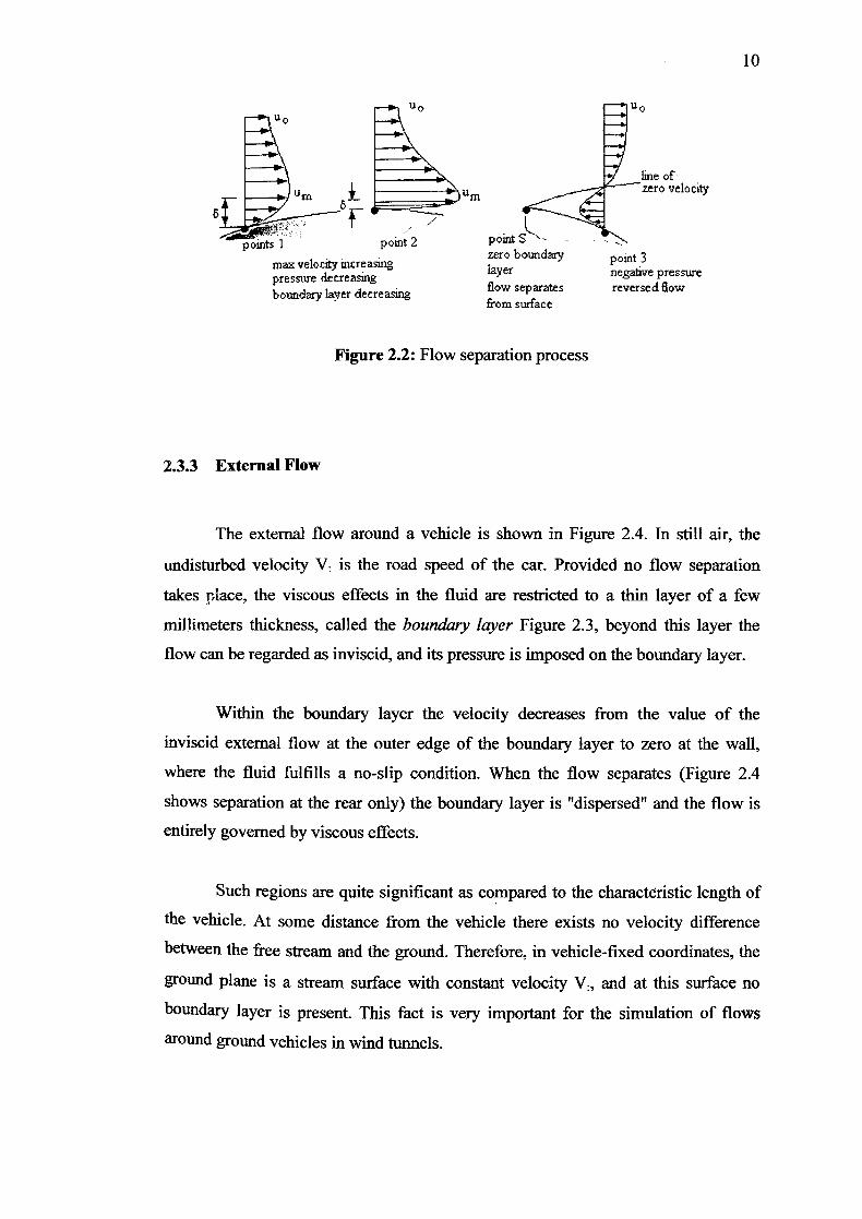
Figure 2.2: Flow separation process
2.3.3 External Flow
The external flow around a vehicle is shown in Figure 2.4. In still air, the
undisturbed velocity V is the road speed of the car. Provided no flow separation
takes place, the viscous effects in the fluid are restricted to a thin layer of a few
millimeters thickness, called the boundary layer Figure 2.3, beyond this layer the
flow can be regarded as inviscid, and its pressure is imposed on the boundary layer.
Within the boundary layer the velocity decreases from the value of the
inviscid external flow at the outer edge of the boundary layer to zero at the wall,
where the fluid fulfills a no-slip condition. When the flow separates (Figure 2.4
shows separation at the rear only) the boundary layer is "dispersed" and the flow is
entirely governed by viscous effects.
Such regions are quite significant as compared to the characteristic length of
the vehicle. At some distance from the vehicle there exists no velocity difference
between the free stream and the ground. Therefore, in vehicle-fixed coordinates, the
ground plane is a stream surface with constant velocity V:, and at this surface no
boundary layer is present. This fact is very important for the simulation of flows
around ground vehicles in wind tunnels.

11
-
Figure 2.3: Boundary layer
The boundary layer concept is valid only for large values of
Rei =(V:/v)>104 [1]
This dimensionless parameter is called the Reynolds number. It is a function
of the speed of the vehicle V:, the kinematic viscosity v of the fluid, and a
characteristic length 1 as defined in Fig. 2.4. The character of the viscous flow around
a bodl depends only on the body shape and the Reynolds number. For different
Reynolds numbers entirely different flows may occur for one and the same body
geometry. Thus the Reynolds number is the dimensionless parameter which
characterizes a viscous flow.
Fig. 2.4: Flow around a vehicle (schematic).
Flows around geometrically similar bodies are called "mechanically similar"
if the Reynolds number according to Eq. (1) has the same value for different body
lengths 1, air speeds V:, and fluid properties v.

12
Mechanical similarity is the basis for model tests. The results of the test on
scale models in terms of dimensionless aerodynamic coefficients are the same as for
the original vehicle if Reynolds numbers are the same.
2.3.4 Boundary Layer Development
In physics and fluid mechanics, the boundary layer is that layer of fluid in the
immediate vicinity of a bounding surface [8]. For flow over any surface, there will
always exist a velocity boundary layer and hence surface friction [4]. On a body of a
car, this surface friction could create drag force that could effect the aerodynamic of
the car. To introduce the concept of boundary layer, consider a flow through a plate
in Figure 2.5.
Free stream
Velocity
boundarylayer T -
Figure 2.5: Flow through a plate
Boundary layer velocity occurs when a consequence of viscous effects
associated with relative motion between a fluid and a surface. A region of the flow
characterized by shear stresses, t and velocity, u gradients. A region between the
surface and the free stream whose thickness increases in the flow direction. The
surface shear stress, ts provides the surface drag force, FD. The surface friction is
strongly depending on the flows condition weather laminar or turbulent flows. On
car's surface, the boundary layer becomes thicker towards the rear of the car. The
thicker the boundary layer, the more easily airflow will separate from the body,
leading to turbulent flow [4].
ö (x)