Descriptive Epidemiology & Routine Analyses: Summarizing Data by Groups/Type/Location

with De-ion® grids
applicatioa ' '
powe:r ci:rc:uit b:reake:rs
outdoor oil breakers
type G o three tank
14.4 thru 69 kv o 500 thru 2500 mva
for 14.4 through 69 kv power transmission systems-20-cycle reclosing and capacitor switching
Type G breakers combine high interrupting capacities, short arcing time and high-speed reclosing with streamlined tank top construction to provide complete reliability, fast fault-clearing and easy maintenance.
··�,' condenser bushing with ASA standard dimensions: Maximum strength with minimum size and weight.
power factor test tap: For quick, ungrounded, bushing power factor tests.
streamlined tank top: Encloses all moving parts, simplifies cleaning and painting.
January, 1961 supersedes DB 33-ZSZ, dated July, 1956
mailed to: E/ZBO/DB: C/331/DB
descriptive bulletin
33-252
page 1
with pneumatic or solenoid operating mechanisms
rated continuous interrupting voltage current capacity kv rating, amps 3-phase, mva
14.4 1200 1000 3000 1500 4000 1500
23 1200 500
34.5 1200 500 1200 1000 1200 1500 2000 2500
46 1200 500 1200 1500
69 1200 1000 1200 1500 1200 2500
interrupting time: 14.4 through 69 kv . . . . . . . • , .5 cycles except 2000-3000-4000 amp • • 8 cycles
www . El
ectric
alPar
tMan
uals
. com
page 2
design featu�es
I
2
3
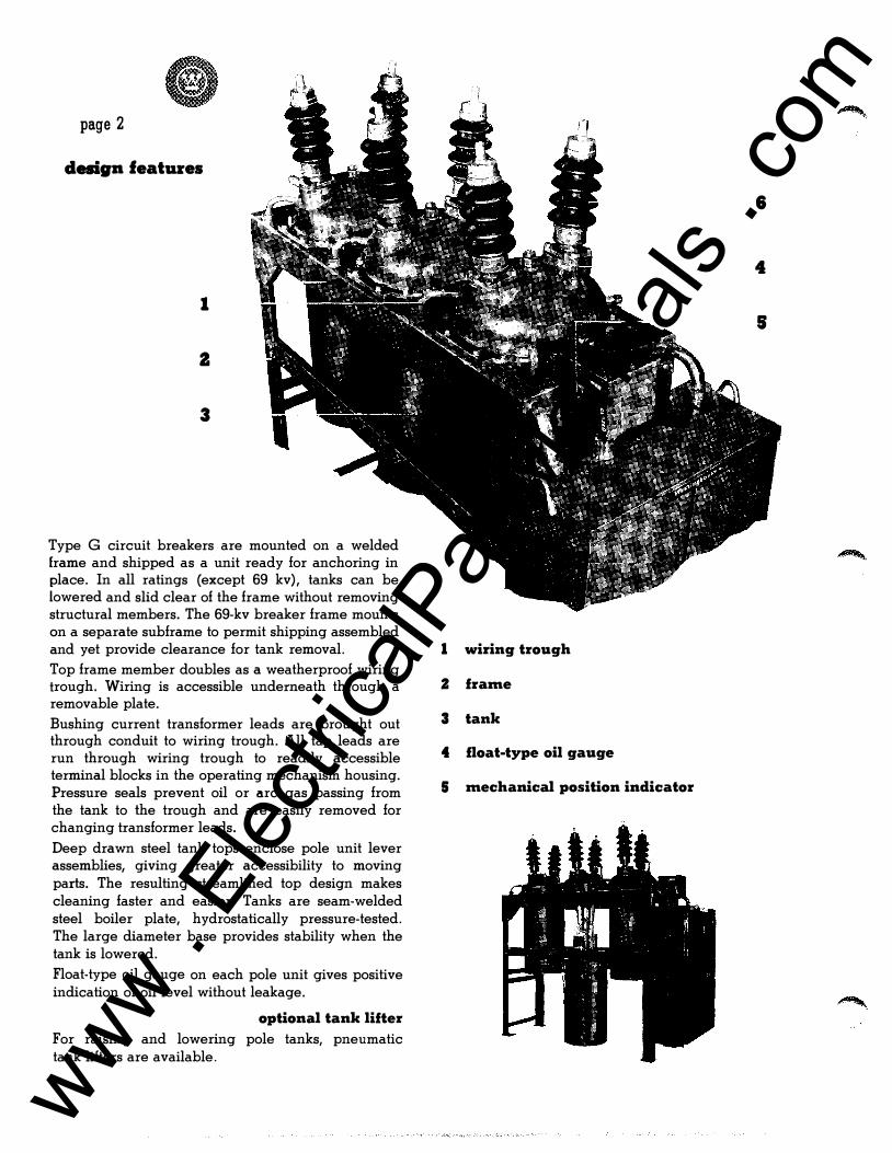
Type G circuit breakers are mounted on a welded frame and shipped as a unit ready for anchoring in place. In all ratings (except 69 kv), tanks can be lowered and slid clear of the frame without removing structural members. The 69-kv breaker frame mounts on a separate subframe to permit shipping assembled and yet provide clearance for tank removal. Top frame member doubles as a weatherproof wiring trough. Wiring is accessible underneath through a removable plate. Bushing current transformer leads are brought out through conduit to wiring trough. All tap leads are run through wiring trough to readily accessible terminal blocks in the operating mechanism housing. Pressure seals prevent oil or arc gas passing from the tank to the trough and are easily removed for changing transformer leads.
Deep drawn steel tank tops enclose pole unit lever assemblies, giving greater accessibility to moving parts. The resulting streamlined top design makes cleaning faster and easier. Tanks are seam-welded steel boiler plate, hydrostatically pressure-tested. The large diameter base provides stability when the tank is lowered. Float-type oil gauge on each pole unit gives positive indication of oil level without leakage.
optional tank lifter
For ralSlng and lowering pole tanks, pneumatic tank lifters are available.
6
4
s
I wiring trough
Z frame
3 tank
4 float-type oil gauge
5 mechanical position indicator
www . El
ectric
alPar
tMan
uals
. com

6 condenser bushings
outdoor oil breakers type G • three tank
14.4 thru 69 kv • 500 thru 2500 mva
The type IC condenser bushings rated 1200 amperes, 23�v through 69 kv are manufactured to ASA standard dimensions. They are interchangeable with transformer bushings of the same current and voltage rating, and with bushings of same rating of other manufacturers built to ASA standard dimensions. The time-proven condenser principle distributes voltage stress evenly through and across the insulation-resulting in a compact design with high cantilever strength and no "weak links" to invite voltage breakdown. Bushings have low power factor and have radio influence level below established standards.
For ratings through 46 kv the entrance conductor is a hollow copper stud threaded for terminal connection. Insulating layers of treated paper are wound around the stud under heat and pressure. Treating compound in the paper binds them into a homogeneous insulation.
Interspersed at regular intervals between the paper layers are sheets of metal foil, which form condenser plates. This series of condensers distributes the voltage stress evenly through and across the insulation.
A single-piece porcelain weather casing surrounds the condenser. The porcelain is flexibly supported at the base by a copper diaphragm and at the top by a flexible copper cap, to compensate for expansion and contraction differentials. Solder-seal joining of porcelain to copper ring and caps forms a hermetically-sealed, moisture-tight housing without gaskets. The space between the porcelain and condenser is filled with a plastic compound which retains its plastic and adhesive properties over the temperature range of breaker operation.
The 1200 ampere, 69 kv rating is oil filled, type 0 construction.
power factor test-tap: Accurate power factor testing of the complete bushing, in place, is simplified by an ungrounded test-tap. The power factor tap is grounded to the bushing flange while the breaker is in service. For testing, the ground is removed. The power factor of the insulation, only, can then be measured, by using an ungrounded test set. This eliminates extraneous effects of oil, De-ion grids, or parallel insulation of incoming lines.
bushing current transformers
On standard breakers, a multi-ratio current transformer is provided on each bushing. These current transformers meet all ASA and NEMA requirements for relaying and indicating instrument applications. If additional standard accuracy current transformers are required, a total of two per bushing can be supplied. Additional current transformers can be installed on customers' breakers at any time without disturbing the mounting of the original transformers.
ASA metering accuracy single-ratio current transformers can be supplied in place of, or in addition to, relaying transformers. Linear couplers can be supplied for bus differential protection.
69 kv
descriptive bulletin
33-ZSZ
page 3
23 through 46 kv
www . El
ectric
alPar
tMan
uals
. com
page 4
design feat111'es, c:oatiaaed
operating mechanisms
completely weatherproof • mechanically and electrically trip-free
two hinged doors for easy access to all parts
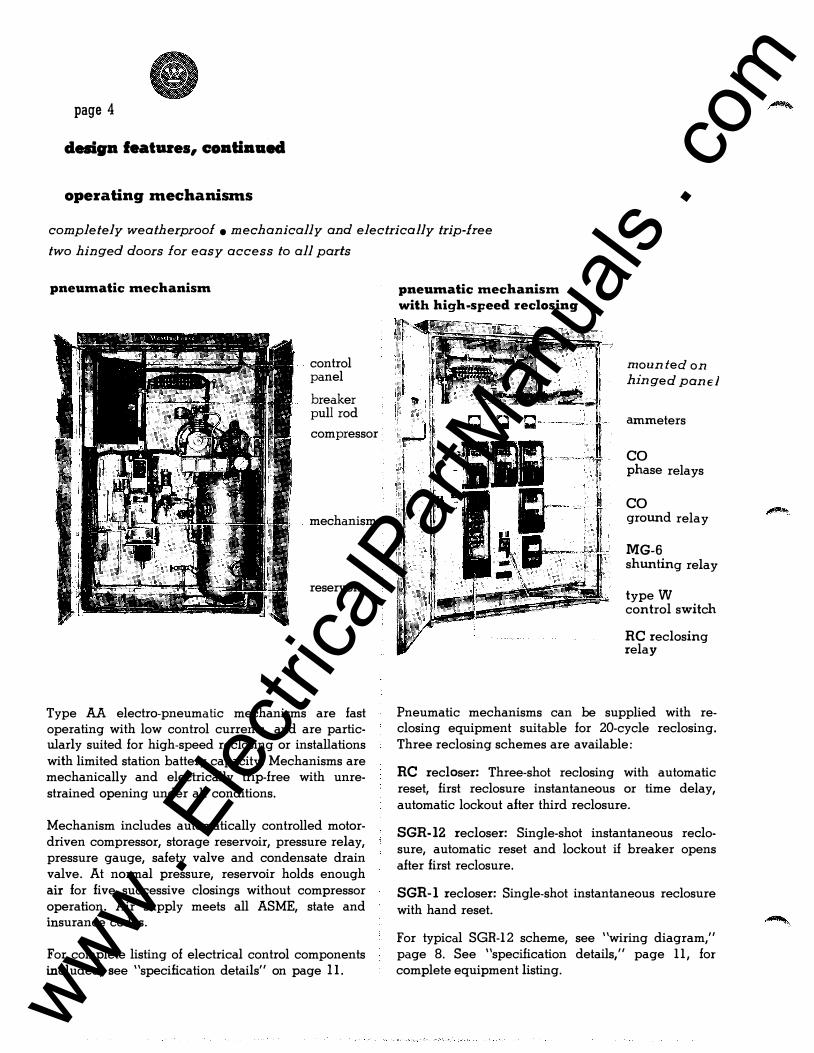
pneumatic mechanism
control panel
breaker pull rod
compressor
mechanism
reservoir
Type AA electro-pneumatic mechanisms are fast operating with low control currents, and are particularly suited for high-speed reclosing or installations with limited station battery capacity. Mechanisms are mechanically and electrically trip-free with unrestrained opening under all conditions.
Mechanism includes automatically controlled motordriven compressor, storage reservoir, pressure relay, pressure gauge, safety valve and condensate drain valve. At normal pressure, reservoir holds enough air for five successive closings without compressor operation. Air supply meets all ASME, state and insurance codes.
For complete listing of electrical control components included, see "specification details" on page II.
pneumatic mechanism with high-speed reclosing
mounted on hinged panE l
ammeters
co phase relays
co ground relay
MG-6 shunting relay
type W control switch
RC reclosing relay
Pneumatic mechanisms can be supplied with reclosing equipment suitable for 20-cycle reclosing. Three reclosing schemes are available:
RC recloser: Three-shot reclosing with automatic reset, first reclosure instantaneous or time delay, automatic lockout after third reclosure.
SGR-12 recloser: Single-shot instantaneous redosure, automatic reset and lockout if breaker opens after first reclosure.
SGR-1 recloser: Single-shot instantaneous reclosure with hand reset.
For typical SGR-12 scheme, see "wiring diagram," page 8. See "specification details," page 11, for complete equipment listing.
www . El
ectric
alPar
tMan
uals
. com
outdoor oil breakers type G • three tank
descriptive bulletin
33-252
14.4 thru 69 kv • 500 thru 2500 mva page 5
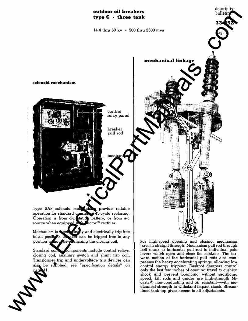
solenoid mechanism
control relay panel
breaker pull rod
mechanism
Type SAF solenoid mechanisms provide reliable operation for standard closing or 45-cycle reclosing. Operation is from d-e station battery, or from a-c source when equipped with Rectox® rectifier.
Mechanism is mechanically and electrically trip-free in all positions. Breaker can be tripped free in any position without de-energizing the closing coil.
Standard control components include control relays, closing coil, auxiliary switch and shunt trip coil. Transformer trip and undervoltage trip devices can also be supplied, see "specification details" on page 11.
mechanical linkage
For high-speed opening and closing, mechanism travel is straight through: Mechanism pull rod through bell crank to horizontal pull rod to individual pole levers which open and close the contacts. The forward motion of the horizontal pull rods also compresses the heavy accelerating springs, allowing low control energy tripping. Dashpot dampers control only the last few inches of opening travel to cushion shock and prevent bouncing without sacrificing speed. Lift rods and guides are high-strength Micarla ®, non-conducting and oil resistant-with mechanical strength to withstand impact shock. Streamlined tank top gives access to all adjustments.
www . El
ectric
alPar
tMan
uals
. com
page 6
interrupting mechanism
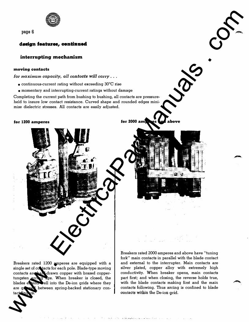
moving contacts
for maximum capacity, all contacts will carry ...
• continuous-current rating without exceeding 30°C rise
• momentary and interrupting-current ratings without damage
Completing the current path from bushing to bushing, all contacts are pressureheld to insure low contact resistance. Curved shape and rounded edges minimize dielectric stresses. All contacts are easily adjusted.
for 1200 amperes
Breakers rated 1200 amperes are equipped with a single set of contacts for each pole. Blade-type moving contacts are hard-drawn copper with brazed coppertungsten arcing tips. When breaker is closed, the blades extend well into the De-ion grids where they are gripped between spring-backed stationary contact fingers.
for 2000 amperes and above
Breakers rated 2000 amperes and above have "tuning fork" main contacts in parallel with the blade contact and external to the interrupter. Main contacts are silver plated, copper alloy with extremely high conductivity. When breaker opens, main contacts part first; and when closing, the reverse holds true with the blade contacts making first and the ma� contacts following. Thus arcing is confined to blade contacts withm the De-ion grid.
� ..
www . El
ectric
alPar
tMan
uals
. com

outdoor oil breakers type G · three tank
descriptive bulletin
33-ZS2
14.4 thru 69 kv • 500 thru 2500 mva page 7
De-ion grid construction
[!] finger-type contact
I Z I fiber plates
[!] blade contact with copper tungsten tip
141 arc horns
I::!J exhaust vents
� oil pockets
De-ion grids for type G breakers are built as a vertical stack of fiber plates. Plates are cut out in the center for moving contact travel, with pockets for trapping oil and vents to release arc gas. Atop the grid mount two spring-backed stationary finger contacts which part slightly to hold the moving blade contact with proper pressure over entire contact surface. Arcing hom is faced with arc-resistant alloy.
arc extinction
l. As the contacts open. nearby oil flashes into ionized gas to conduct a heavy arc between the stationary and moving contacts. The arc terminals quickly move to stationary arc hom, and moving contact arc tip protects contact surfaces from burning.
2. The top section interrupts high current arcs with a minimum of arc length and energy. It is composed of oil pockets, vent plates and a splitter plate. When a high current arc is drawn, pressure builds up quickly in this section.
The gasses formed are vented through the channels provided. Flow of gas into these channels forces the arc to move into the direction of the flow. The arc is drawn, de-ionized and extinguished in a period of one to two cycles.
The remainder of the grid is composed of alternate oil pockets and close-fitting plates which serve to interrupt a middle range or low current.
During low current interruptions, relatively little pressure is generated. The action of the top section is reduced but as the arc is lengthened, it is continuously exposed to new supplies of fresh oils. The arc is lengthened and cooled, causing rapid deionization and interruption.
3. After the arc has been completely extinguished and contacts are fully open, fresh oil replaces gas in grids.
www . El
ectric
alPar
tMan
uals
. com
page 8
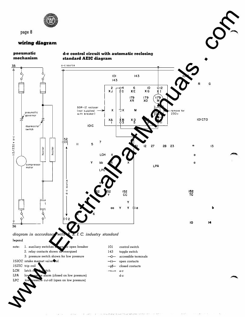
wbing cliagl'am
pneumatic mechanism
35
pneumatrc /governor
thermostat/ switch
u ·' c
d-e control circuit with automatic reclosing standard AEIC diagram
a -c source
101 143
143
2 ,-( 4 6 10 XJ c XE XG
179 179 XR xo
SGR-12 recloser (not supplied� X X M woth breaker)
XA B XD XF I 3 5 9
IOIC
52 7
0 o<> (+1 5 II I 51 12 27
N "' "' ' c c l() "' "' .c .c LCH X
y bb X compressor motor
LPC
"' � y " � 0
152 152 I " X y
1 a a
12 6
(-) 2
36
diagram in accordance with A. E. L C. industry standard legend
note: 1. auxiliary switches shown for open breaker
2. relay contacts shown de-energized
3. pressure switch shown for low pressure
152CC intake magnet valve coil
152TC trip coil
LCH latch check switch
LPA low pressure alarm (closed on low pressure)
LPC low pressure cut-off (open on low pressure)
101 143 --o--H---tf-
X
X LPA
152 cc
y y y �a
control switch
toggle switch
accessible terminals
open contacts
closed contacts
a-c
d-e
12 I
H II
28
IOIT
t-re move for 30 v 2
23 0
152 TC
10
a
a
R G
IOICTO
13
b
14
·"""'
www . El
ectric
alPar
tMan
uals
. com
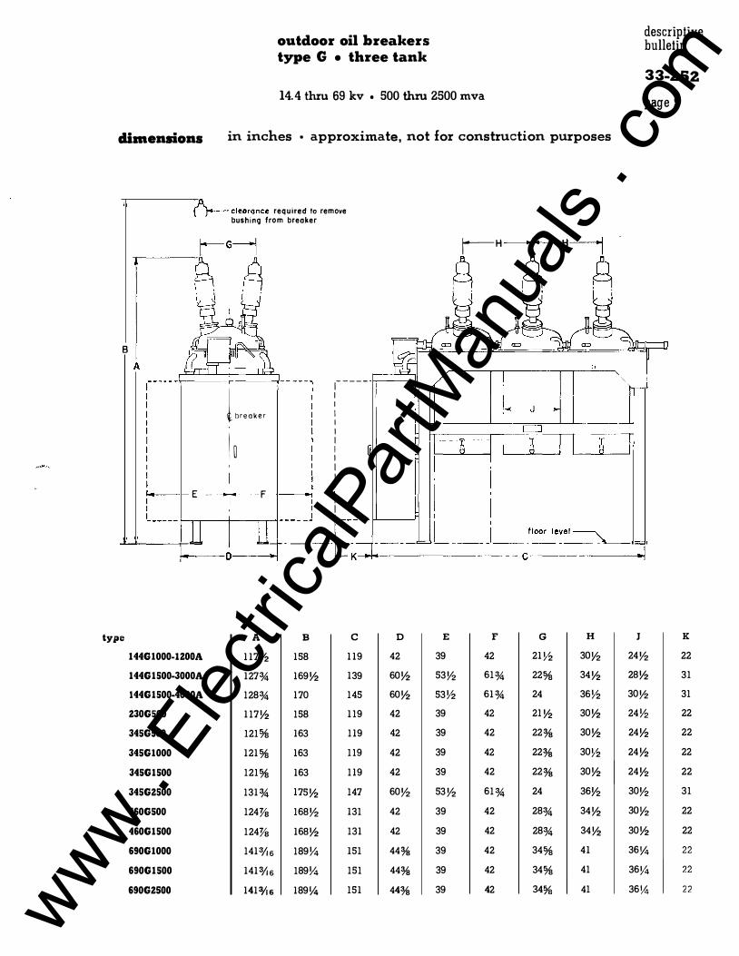
outdoor oil breakers type G • three tank
14.4 thru 69 kv • 500 thru 2500 mva
dimensions in inches • approximate, not for construction purposes
B
�clearance required to remove bushing from breaker
�breaker
I � '
E -- + - F
�-----1 I I I I I I I I I
I
, I
r--H
� I� i
descriptive bulletin
33-ZSZ
page 9
.....__,__ __ ::: __ ---.-�-�=�- [_-.,-�-��----���--==�---�===-Cf�lo_o_r� -le_� -e_l-=:_-=:_-=:__).. __ ----1�01
type A B c D E F G H J K
144G 1000-IZOOA 117Y:! 158 119 42 39 42 21 Y:! 3oy2 24V2 22
144G 1500-3000A 127% 169Y:! 139 60Y:! 53V2 61% 22% 34Y:! 28Y:! 31
144G 1500-4000A 128% 170 145 60Y:! 53Y:! 61% 24 36Y:! 30V2 31
Z30G500 117Y:! 158 119 42 39 42 21 Y:! 30Y:! 24Y:! 22
345G500 121% 163 119 42 39 42 22% 30Y:! 24Y:! 22
345G1000 121% 163 119 42 39 42 22% 30Y:! 24Y:! 22
345G1500 121% 163 119 42 39 42 22% 30Y:! 24Y2 22
345GZ500 131% 175Y:! 147 60V2 53V2 61% 24 36Y2 30V2 31
460G500 124% 168V2 131 42 39 42 28% 34Y:! 3oy2 22
460G1500 124% 168Y:! 131 42 39 42 28% 34Y:! 30Y:! 22
690G1000 1413/i 6 189Y4 151 44% 39 42 34% 41 36Y4 22
690G1500 1413/i 6 189Y4 151 44% 39 42 34% 41 36Y4 22
690GZSOO 14131!6 189Y4 151 44% 39 42 34% 41 36Y4 22 www . El
ectric
alPar
tMan
uals
. com
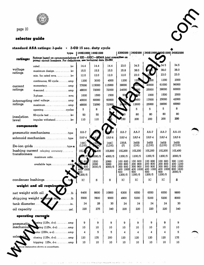
page 10
selector guide
standard ASA ratings: 3-pole 2-CO 15 sec. duty cycle
type 1144G10001144G1500 1 Z30G500 1345G500 1345GIOOOI345G15001345GZ500
ratiags: Ratings based on recommendations of EEI-AEIC-NEMA joint committee on · ·
power circuit breakers. For definitions, see technical data 33-060
rated ...................... kv 14.4 14.4 14.4 23.0 34.5
voltage maximum design ... ........ kv 15.5 15.5 15.5 25.8 38.0 ratings
min. for rated mva .. . ....... kv 12.0 12.0 12.0 12.0 23.0
continuous, 60 cycle ....... amp 1200 3000 4000 1200 1200
current momentary ............... amp 77000 115000 115000 38000 20000
ratings 4-second .. ............... amp 48000 72000 72000 24000 12600
3-phase .................. mva 1000 1500 1500 500 500
interrupting rated voltage ............. amp 40000 60000 60000 12600 8400
ratings maximum ..... . . . . . . . . . . . amp 48000 72000 72000 24000 12600
opening ................ cycles 5 8 8 5 5
insulation 60-cyde test . . ............. kv 50 50 50 60 80
level impulse withstand . .. . ... ... kv 110 110 110 150 200
compoaeats
pneumatic mechanisms .... ......... type AA-7 AA-10 AA-10 AA-7 AA-7
solenoid mechanism ...... ......... type SAF-4 SAF-6 SAF-6 SAF-4 SAF-4
144C 144C 144C 230A 345B De-ion grids . ............. ..... ..... type"' (LDH) (LDH) (LDH) (F) (DH)
bushing current relaying accuracy ... 101200 101400 101800 101200 101200 transformers
maximum ratio .... 1200/5 3000/5 4000/5 1200/5 1200/5
100 600 1500 2000 100 600 100 600 available taps ............ amp 200 800 2000 3000 200 800 200 800
300 900 3000/5 4000/5 300 900 300 900 400 1000 400 1000 400 1000 500 500 500 1200/5 1200/5 1200/5
condenser bushings . .... ... . . ... .... type IC s s IC IC
weight and oil reqahemeats
net weight with oil ...... . . . ........ .. lb 6400 8600 10800 6300 6550
shipping weight without oil . ........ lb 5500 7800 9000 4900 5200
tank diameter . ... .... ... ........ ...... in. 24 28 30 24 24
oil capacity ................... ..... gal. 220 275 340 220 220
operatiag curreats
pneumatic closing (125v, d-e) ........ amp 9 9 9 9 9
mechanism tripping (125v, d-e) ....... amp 10 10 10 10 10
motor (230v, a-c) .......... amp 4 5 5 4 4
solenoid closing (125v, d-e) ........ amp 120 175 200 120 120
tripping 125v, d-e ........ amp 10 10 10 10 10
A Previous desiqnation shown in parenthesis.
34.5 34 5 34.5
38.0 38.0 38.0
23.0 23.0 23.0
1200 1200 2000
40000 61000 96000
25000 38000 60000
1000 1500 2500
17000 25000 42000
25000 38000 60000
5 5 8
80 80 80
200 200 200
AA-7 AA-7 AA-10
SAF-4 SAF-4 SAF-6
345B 345B 345B (1DH) (1DH) (CDH)
101200 101200 101400
1200/5 1200/5 2000/5
100 600 100 600 300 1100 200 800 200 800 400 1200 300 900 300 900 500 1500 400 1000 400 1000 800 1600 500 500 2000/5 1200/5 1200/5
IC IC s
6550 6550 9800
5200 5200 8000
24 24 30
220 220 340
9 9 9
10 10 10
4 4 5
120 120 175
10 10 10
www . El
ectric
alPar
tMan
uals
. com
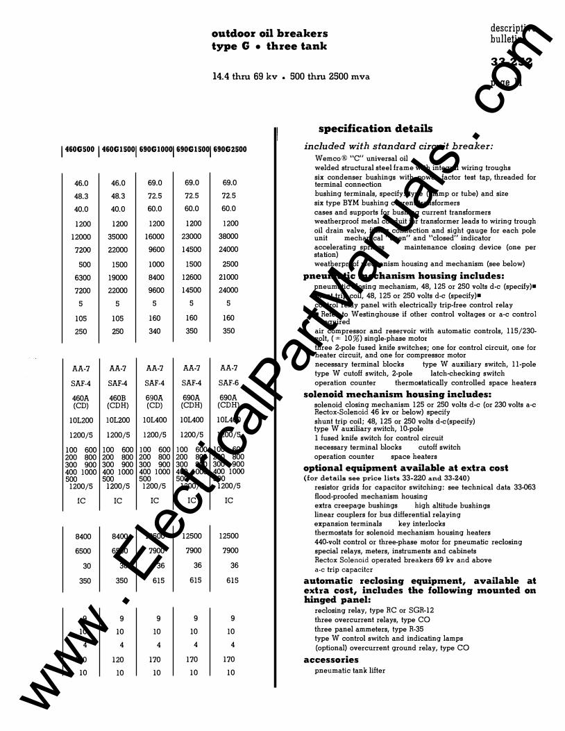
outdoor oil breakers type G • three tank
14.4 thru 69 kv • 500 thru 2500 mva
specification details
descriptive bulletin
33-ZSZ
page ll
1460GSOO 1460G15001690G10001690G15001690G2500 included with standard circuit breaker: Wemco® "C" universal oil
46.0
48.3
40.0
1200
12000
7200
500
6300
7200
5
105
250
AA-7
SAF-4
460A (CD)
10L200
1200/5
100 600 200 800 300 900 400 1000 500 1200/5
IC
8400
6500
30
350
9
10
4
120
10
46.0
48.3
40.0
1200
35000
22000
1500
19000
22000
5
105
250
AA-7
SAF-4
460B (CDH)
10L200
1200/5
100 600 200 800 300 900 400 1000 500
1200/5
IC
8400
6500
30
350
9
10
4
120
10
69.0
72.5
60.0
1200
16000
9600
1000
8400
9600
5
160
340
AA-7
SAF-4
690A (CD)
10L400
1200/5
100 600 200 800 300 900 400 1000 500 1200/5
IC
12500
7900
36
615
9
10
4
170
10
69.0
72.5
60.0
1200
23000
14500
1500
12600
14500
5
160
350
AA-7
SAF-4
690A (CDH)
10L400
1200/5
100 600 200 800 300 900 400 1000 500
1200/5
IC
12500
7900
36
615
9
10
4
170
10
69.0
72.5
60.0
1200
38000
24000
2500
21000
24000
5
160
350
AA-7
SAF-6
690A (CDH)
10L400
1200/5
100 600 200 800 300 900 400 1000 500
1200/5
IC
12500
7900
36
615
9
10
4
170
10
welded structural steel frame with integral wiring troughs six condenser bushings with power factor test tap, threaded for terminal connection bushing terminals, specify: type (clamp or tube) and size six type BYM bushing current transformers cases and supports for bushing current transformers weatherproof metal conduit for transformer leads to wiring trough oil drain valve, filling connection and sight gauge for each pole unit mechanical "open" and "closed" indicator accelerating springs maintenance closing device (one per station) weatherproof mechanism housing and mechanism (see below)
pneumatic mechanism housing includes: pneumatic closing mechanism, 48, 125 or 250 volts d-e (specify)• shunt trip coil, 48, 125 or 250 volts d-e (specify)• control relay panel with electrically !rip-free control relay • Refer to Westinghouse if other control voltages or a-c control
required air compressor and reservoir with automatic controls, 115/230-volt, ( ± 10%) single-phase motor three 2-pole fused knife switches; one for control circuit, one for heater circuit, and one for compressor motor necessary terminal blocks type W auxiliary switch, 11-pole type W cutoff switch, 2-pole latch-checking switch operation counter thermostatically controlled space heaters
solenoid mechanism housing includes: solenoid closing mechanism 125 or 250 volts d-e (or 230 volts a·c Rectox-Solenoid 46 kv or below) specify shunt trip coil; 48, 125 or 250 volts d-c(specify) type W auxiliary switch, 10-pole I fused knife switch for control circuit necessary terminal blocks cutoff switch operation counter space heaters
optional equipment available at extra cost (for details see price lists 33-220 and 33-240)
resistor grids for capacitor switching: see technical data 33-063 flood-proofed mechanism housing extra creepage bushings high altitude bushings linear couplers for bus differential relaying expansion terminals key interlocks thermostats for solenoid mechanism housing heaters 440-volt control or three-phase motor for pneumatic reclosing special relays, meters, instruments and cabinets Rectox Solenoid operated breakers 69 kv and above a-c trip capacitor
automatic reclosing equipment, available at extra cost, includes the following mounted on hinged panel:
reclosing relay, type RC or SGR-12 three overcurrent relays, type CO three panel ammeters, type R-35 type W control switch and indicating lamps (optional) overcurrent ground relay, type CO
accessories pneumatic tank lifter
www . El
ectric
alPar
tMan
uals
. com
descriptive bulletin
33-252
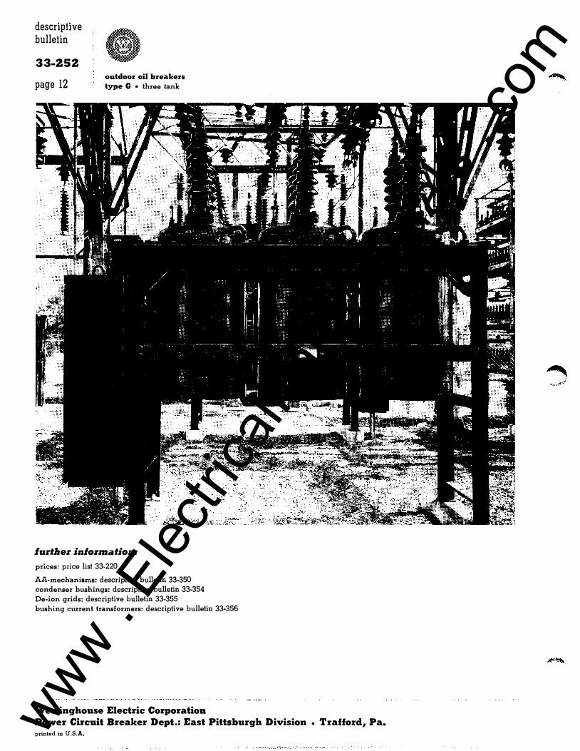
page 12 outdoor oil breakers type G o three tank
lurtlaer in/ormation:
prices: price list 33-220
AA-mechanisms: descriptive bulletin 33-350 condenser bushings: descriptive bulletin 33-354 De-ion grids: descriptive bulletin 33-355 bushing current transformers: descriptive bulletin 33-356
Westinghouse Electric Corporation Power Circuit Breaker Dept.: East Pittsburgh Division o Trafford, Pa. printed in U.S.A. www .
Elec
tricalP
artM
anua
ls . c
om