
Deploying BusinessObjects Enterprise in a Complex Network ...
28
36 CHAPTER In this chapter Deploying BusinessObjects Enterprise in a Complex Network Environment Introduction PDF 896 Understanding Network Protocols PDF 896 Understanding Firewall Types PDF 899 Configuring the BusinessObjects Enterprise Architecture for Your Network Environment PDF 902 Interaction Between the WCS and the WC PDF 905 Deploying BusinessObjects Enterprise with an IP Packet Filtering Firewall PDF 911 Using BusinessObjects Enterprise with NAT PDF 917 Exploring the NAT and BusinessObjects Enterprise Relationship PDF 917 BusinessObjects Enterprise and Proxy Servers PDF 919
Transcript of Deploying BusinessObjects Enterprise in a Complex Network ...

36CHAPTER
In this chapter
Deploying BusinessObjectsEnterprise in a Complex NetworkEnvironment
Introduction PDF 896
Understanding Network Protocols PDF 896
Understanding Firewall Types PDF 899
Configuring the BusinessObjects Enterprise Architecture for Your Network Environment PDF 902
Interaction Between the WCS and the WC PDF 905
Deploying BusinessObjects Enterprise with an IP Packet Filtering Firewall PDF 911
Using BusinessObjects Enterprise with NAT PDF 917
Exploring the NAT and BusinessObjects Enterprise Relationship PDF 917
BusinessObjects Enterprise and Proxy Servers PDF 919

PDF 896 Chapter 36 Deploying BusinessObjects Enterprise in a Complex Network Environment
IntroductionOne key design consideration for BusinessObjects Enterprise was for the delivery of infor-mation to be deployed as part of any Web-based delivery platform—intranet, extranet, orInternet. Increasingly, organizations are looking to standardize the access to corporate infor-mation within a Web-based infrastructure. Companies are now able to support a close rela-tionship with their external constituents—be they customers or suppliers—through thedelivery of information over the Web. Furthermore, considerable economies of scale can berealized by using the same architecture to deliver information internally.
Often, the means by which information can be rendered is through the display of a CrystalReport (or multiple Crystal Reports) as an integral part of a web page executing on a clientbrowser. Such integration with a company’s Web-based information delivery system requiresthat the vehicle for providing that information (for example, a Crystal Report managed byBusinessObjects Enterprise and integrated completely into a web page) can also conform tothe company’s security requirements. In a nutshell, no matter what firewall standards a com-pany chooses to adopt, BusinessObjects Enterprise not only must be able to be configuredwithin these standards, it also must do so without compromising the integrity (or perfor-mance) of information management and delivery.
This chapter concentrates on how the architecture of BusinessObjects Enterprise allows forcomplete integration into complex networks with firewall systems to provide informationdelivery across intranets and the Internet without compromising network security. Moreoften than not, providing examples of how BusinessObjects Enterprise works with complexfirewall scenarios produces enough information to relate this chapter to other networkdeployment scenarios.
To understand how BusinessObjects Enterprise works in a complex network environment, areview of several server and system processes is provided in this chapter, extending discus-sions put forth from earlier chapters in this book.
Essentially, this chapter concentrates on firewalls and illustrates how BusinessObjectsEnterprise can be deployed within the various firewall architectures commonly available.First, however, you start by learning to understand firewalls and looking at the supportingtechnology.
A firewall is a set of related programs located at a network gateway server (that is, the pointof entry into a network), which protect the resources of a private network from users ofother networks. It restricts people to entering and leaving your network at a carefully con-trolled point. A firewall is put in place to protect a company’s intranet from being improp-erly accessed through the Internet. Additionally, firewalls can be used to enforce securitypolicies and to log Internet activity.
Understanding Network ProtocolsTo have a clear understanding of how firewalls operate (and how BusinessObjects Enterpriseis configured within a firewall), review the major protocols used within the Internet.
36

PDF 897Understanding Network Protocols
Major Internet Protocols and Services A standard number of Internet services work in conjunction with firewalls. These servicesare the primary reason for firewalls because companies want to control who and what goesover these services to their internal network.
HyperText Transfer Protocol
HTTP is the primary protocol that underlies the Web: It provides users access to the filesthat make up the Web. These files can be in many different formats (text, graphics, audio,video, and so on). This protocol is in clear text and usually operates over TCP/IP. So a typi-cal command in HTTP asking for a red picture might look like 192.168.0.16 ->naisan.net GET /~bigdir/agenmc/red.gif HTTP/1.0.
Simple Mail Transfer Protocol
SMTP is the Internet standard protocol for sending and receiving electronic mail. The mostcommon SMTP server on Windows NT is Microsoft Exchange. Although SMTP is used toexchange electronic mail between servers, users who are reading electronic mail that hasalready been delivered to a mail server do not use SMTP. When they transfer that mail fromthe server to their desktop they use another protocol, POP (Post Office Protocol). SMTP isalso a clear text protocol, so you could send an e-mail by connecting to a SMTP server, andthen entering this:
MAIL From:[email protected] To:[email protected] Dude! Who stole my soccer ball?.QUIT
File Transfer Protocol
FTP is the Internet standard protocol for file transfers. Most Web browsers support FTP, aswell as HTTP, and automatically use FTP to access locations with names that begin ftp. somany people use FTP without ever being aware of it. FTP was the initial transfer protocolused for the Internet before the advent of the World Wide Web. FTP is also an open textprotocol.
Remote Terminal Access
Remote terminal access is most commonly known as Telnet. Telnet is the standard forremote terminal access on the Internet, and enables you to provide remote text access foryour users.
DNS Hostname/Address Lookup
A naming service translates between the names that people use and the numerical addressesthat machines use. The primary name lookup system on the Internet is Domain NameSystem (DNS), which converts between hostnames and IP addresses.
36

PDF 898 Chapter 36 Deploying BusinessObjects Enterprise in a Complex Network Environment
TCP/IP TCP/IP (Transmission Control Protocol/Internet Protocol) is a family of basic communica-tions protocols used on the Internet. TCP/IP uses what is termed a data packet to transferinformation over the Internet from one computer to another. Packets contain the data thatyour browser shows when it is surfing the Net. Each packet is small, so many packets areneeded to transmit the data contained on one HTML page. As more and more peopleaccess the Net and transmit data, more and more packets are being transferred. Thisincreases the need to make sure all the packets that arrive at your door (Web server) arereally supposed to come in.
The TCP/IP Protocol Stack
The TCP/IP protocol stack, which makes up each packet, is constructed of the followinglayers, from the highest to lowest:
■ Application layer (FTP, Telnet, HTTP)
■ Transport layer (TCP or UDP)
■ Internet layer (IP)
■ Network Access layer (Ethernet, ATM)
Packets are constructed in such a way that layers for each protocol used for a particular con-nection are built atop one another.
At the Application layer the packet consists simply of the data to be transferred, such as anHTML page, which is simply text. As it moves down the layers, trying to reach the wire(network cable) that it needs to go out on, each layer adds a header to the packet; this pre-serves the data from the previous level. These headers are then used to determine where thepacket is going and to make sure it all gets there in one piece. When the data packet reachesits destination, the process is reversed. In the end, therefore, all that TCP/IP is responsiblefor is specifying how data can make its way from one computer to another. These computersmight reside on the same network or in completely different locations. As far as firewalls areconcerned, the main thing to remember is that it is not so much about how the packet phys-ically gets to its destination but what is in that packet and whether it is supposed to be there.
TCP/IP Rules
TCP/IP is ideally suited to being the standard protocol for the delivery of informationthrough both external and internal network architectures for the following reasons:
■ TCP/IP is packet-based. There are no set limits to the size of a given message becauselong messages are broken down into multiple (and linked) packets.
■ TCP/IP provides for decentralized control. After you own the domain name/number(businessobjects.com) you can assign anything in front of it to expand your domain.
36

PDF 899Understanding Firewall Types
Support.businessobjects.com is an expansion to route traffic specifically to technicalsupport within the Business Objects organization.
■ Communicating devices are peers; every computer on the network is a peer. Eachdevice can take on the role of either requester or server in the flow of informationacross multiple computers.
■ TCP/IP is routable and easy to transmit between networks. The same rules applywhether communicating through an external or internal network.
■ TCP/IP is an open free standard, an important consideration because this, combinedwith the other reasons detailed in this list, has led to widespread adoption.
Network Ports A typical server sets up services to listen on ports. A port is a “logical connection place” andspecifically, using the Internet’s protocol, TCP/IP, the way a client program specifies a par-ticular server program on a computer in a network. Higher-level applications that useTCP/IP, such as the Web protocol HTTP, have ports with preassigned numbers. These areknown as well-known ports that have been assigned by the Internet Assigned NumbersAuthority (IANA). Other application processes are given port numbers dynamically for eachconnection. When a service starts (or is initialized), it is said to bind to its designated portnumber. Any client program that wants to use that service must issue its request to the des-ignated port number.
Port numbers range from 0 to 65536. Ports 0 to 1024 are reserved for use by certain privi-leged services. For example, for the HTTP service, port 80 is defined as a default. When aclient makes a request, the server will assign that request to a port above 1024. Two piecesof information need to be passed in the TCP/IP header: the originating address of thesource request, and the target address of the destination computer. This establishes the con-nection points for message exchange. You typically use the shorthand IP:port to denote anaddress, such as 192.9.0.95:1844, which refers to IP address 192.9.0.95 and port 1844 of thatIP address.
Understanding Firewall TypesFirewalls primarily function using at least one of three methods: packet filtering, NetworkAddress Translation (NAT), and proxy services. BusinessObjects Enterprise works with eachof these firewall types. Packet filtering rejects TCP/IP packets from unauthorized hosts andrejects connection attempts to unauthorized services. NAT translates the IP address of inter-nal hosts to hide them from outside access—NAT is often referred to as “IP masquerading.”Proxy services make high-level application connections on behalf of internal hosts to com-pletely break the network layer connection between internal and external hosts. Let’s look atthese different types in more detail.
36

PDF 900 Chapter 36 Deploying BusinessObjects Enterprise in a Complex Network Environment
Packet Filtering Packet filtering inspects and selectively deletes packets before they are delivered to the des-tination computer. Packet filtering can delete packets based on the following:
■ The address from which the data is coming
■ The address to which the data is going
■ The session and application ports being used to transfer the data
■ The data contained by the packet
Typically, there are two types of packet filtering: stateful and stateless. Stateful packet filtersremember the state of connections at the network and session layers by recording the estab-lished session information that passes through the filter gateway. The filter then uses thatinformation to discriminate valid return packets from invalid connection attempts. Statelesspacket filters do not retain information about connections in use; they make determinationspacket-by-packet based only on the information contained within the packet.
Understanding NATNAT converts private IP addresses in a private network to globally unique public IPaddresses for use on the Internet. Its main purpose is hiding internal hosts. It makes itappear that all traffic from your site comes from a single IP address. NAT hides internal IPaddresses by converting all internal host addresses to the address of the firewall as packetsare routed through the firewall. The firewall then retransmits the data payload of the inter-nal host from its own address using a translation table to keep track of which sockets (con-nections) on the exterior interface equate to which sockets on the interior interface. This isalso a simple proxy.
There are several NAT types including the following:
■ Static translation (port forwarding)—This is when a specific internal networkresource has a fixed translation that never changes. If you’re running an e-mail serverinside a firewall, a static route for port 25 of the external address can be establishedthrough the firewall that maps to the right machine internally.
■ Dynamic translation (automatic, hide mode, or IP masquerade)—This is where alarge group of internal clients share a small group of external IP addresses for the pur-pose of expanding the internal network address space. Because a translation entry doesnot exist until an interior client establishes a connection out through a firewall, externalcomputers have no method to address an internal host that is protected using a dynami-cally translated IP address.
■ Load balance translation—In this configuration, a single IP address and port is trans-lated to a pool of identically configured servers—a single IP address serves a group ofservers. This allows you to spread the load of one very popular website across severaldifferent servers by using the firewall to choose which internal server each external clientshould connect to on either a round-robin or balanced load basis. This is somewhat
36

PDF 901Understanding Firewall Types
similar to dynamic translation in reverse—the firewall chooses which server each con-nection attempt should be directed to from among a pool of clones.
■ Network redundancy translation—Multiple Internet connections are attached to asingle NAT firewall. The firewall chooses and uses each Internet connection based onload and availability. The firewall is connected to multiple ISPs through multiple inter-faces and has a public masquerade address for each ISP. Each time an internal hostmakes a connection through the firewall, that firewall decides, on a least-loaded basis,on which network to establish the translated connection. In this way, the firewall is ableto spread the internal client load across multiple networks.
Understanding Proxy ServersProxy servers were originally developed to cache web pages that were frequently accessed.As the Web went supernova the proxies became less effective as caching mechanisms, butanother asset of proxy servers became evident: Proxy servers can hide all the real users of anetwork behind a single machine, and they can filter URLs and drop suspicious or illegalcontent, or hide the identity of a user. The primary purpose of the majority of proxy serversis now serving as a sort of firewall rather than Web caching.
Proxy servers regenerate high-level service requests on an external network for their clientson a private network. This effectively hides the identity and number of clients on the inter-nal network from examination by an external network user.
Proxies work by listening for service requests from internal clients and then sending thoserequests on the external network as if the proxy server itself was the originating client.When the proxy server receives a response from the public server, it returns that response tothe original client as if it were the originating public server. You can even use the proxyserver to load balance similar to the NAT load balancing. As far as the user is concerned,talking to the proxy server is just like talking directly to the real server. As far as the realserver is concerned, it’s talking to a user on the host that is running the proxy server; itdoesn’t know that the user is really somewhere else.
The use of proxies does not require any special hardware, but something somewhere has tobe certain that the proxy server gets the connection. This might be done on the client endby telling it to connect to the proxy server (Socks), or it might be done by intercepting theconnection without the client’s knowledge and redirecting it to the proxy server.
Socks is a protocol that a proxy server can use to accept requests from client users in a com-pany’s network so that it can forward them across the Internet. Socks uses sockets, a methodfor communication between a client program and a server program in a network. A socket isan end point in a connection. Sockets are created and used with a set of programmingrequests or function calls to represent and keep track of individual connections. A proxymust exist for each service. Protocols for which no proxy service is available cannot be con-nected through a proxy except by a generic TCP proxy service that would work similar to a NAT.
36

PDF 902 Chapter 36 Deploying BusinessObjects Enterprise in a Complex Network Environment
Configuring the BusinessObjects EnterpriseArchitecture for Your Network Environment
Chapter 25, “BusinessObjects Enterprise Architecture,” introduced the components thatmake up the BusinessObjects Enterprise architecture. However, before looking at howBusinessObjects Enterprise can be configured to support the implementation of the firewalltypes described previously, it is necessary to review the architecture of BusinessObjectsEnterprise, concentrating on how the components that make up the complete productarchitecture communicate with each other. In fact, the mechanism employed to supportserver communications has a significant bearing on how BusinessObjects Enterprise can bedeployed with one or multiple firewalls.
Additionally, more detail needs to be provided about the relationship between the WC, theWeb server, and the Web Component Server. This will be done in a later section; first, youwill examine the core of BusinessObjects Enterprise server communication—theFramework.
Reviewing the FrameworkFrom your investigation of the BusinessObjects Enterprise architecture in previous chapters,you know that at the core of BusinessObjects Enterprise is a communication layer called theBusinessObjects Enterprise Framework. The Framework is made up of a collection of ser-vices, which provides a series of Business Intelligence–related functions implemented by oneor more BusinessObjects Enterprise services. It is, effectively, a CORBA bus integratingEnterprise information management facilities (Security, Deployment, Administration, and soon) with the CORBA 2 Open Standard services (Naming, Trading, Event, and so on).Common Object Request Broker Architecture (CORBA) is an architecture and specification forcreating, distributing, and managing distributed program objects in a network. It allows pro-grams in different locations to communicate in a network through an “interface broker.”
Although CORBA is at the core of the Framework, it is hidden from BusinessObjectsEnterprise administrators and developers (and, therefore, does not form part of the discus-sion of administration in Chapter 27, “Administering and Configuring BusinessObjectsEnterprise”). No configuration needs be done with CORBA that would be done differentlyfrom any other TCP/IP application. Some definition of port numbers is all that is requiredas far as Framework Administration is concerned.
However, for the purpose of using firewalls one concept about CORBA needs to be under-stood—the IOR. The IOR (Interoperable Object Reference) is a unique identifier for an objectand contains information about the CORBA object itself. For example, the Report JobServer appears to other CORBA clients using the Framework as an object that is availablefor those clients to use. Each time a server in the Framework requires the use of anotherserver object, it requests information about that object. This information comes in the formof an IOR. The IOR includes the IP address and port to be used for returning messages—critical when working with firewalls.
36

PDF 903Configuring the BusinessObjects Enterprise Architecture for Your Network Environment
To summarize, BusinessObjects Enterprise uses CORBA for intra-server communication.Administrators and developers are not exposed to the technology, nor are they required towork with it; however, it can become important in terms of firewall configuration.
BusinessObjects Enterprise and TCP/IP CommunicationWith standard TCP/IP communications, two servers that communicate with each other doso over a single point-to-point connection. The use of CORBA in the BusinessObjectsEnterprise Framework, however, lends a slightly different flavor. In an environment wheremany requests are to be served, traffic on a particular port can be overwhelming and slowthe operations of the server—leading, obviously, to performance problems. BusinessObjectsEnterprise avoids this by listening on one port and sending on others. Within theBusinessObjects Enterprise environment, therefore, communication consists of the openingand closing of multiple ports for a single request/service interaction. In BusinessObjectsEnterprise server-to-server communication, after the initial connection is complete, commu-nication stops on this channel. Instead, another channel is established to send data back andforth, leaving the server that is listening on a given port free to service the next connectionrequest quickly and efficiently.
Understanding Web Connector and Web Component ServerCommunication
The gateways to the BusinessObjects Enterprise information delivery environment areeither the Web Component Server (WCS) in the COM environment, the Java applicationserver in the Java environment, or the .NET application server in the .NET environment.These communicate via the CE-SDK to the BusinessObjects Enterprise Framework.Because there are multiple configurations available with BusinessObjects Enterprise depend-ing on the platform and technologies used in each organization, a brief exploration clarifiesthe remainder of this chapter.
Three main types of configuration are possible at the application level of theBusinessObjects Enterprise Architecture: the COM configuration, Java configuration, and.NET configuration. Note that all of these configurations could be connected to oneBusinessObjects Enterprise installation, allowing a diverse organization to leverage existingtechnology to write applications against one installation of BusinessObjects Enterprise.
36
N O T EBusinessObjects Enterprise supports three implementations of its SDK simultaneously.That means one implementation can support communication from Java, .NET, and COMenvironments at the same time. This enables organizations to leverage their inherentskill-sets when developing with BusinessObjects Enterprise and also facilitates ongoingsystem availability through enterprise development standards changes (for example,moving from a COM-based shop to a J2EE-based organization).
The COM environment is common on Windows platforms and uses the BusinessObjectsEnterprise COM SDK, CSP or ASP pages, a BusinessObjects Enterprise WCS, and a

PDF 904 Chapter 36 Deploying BusinessObjects Enterprise in a Complex Network Environment
BusinessObjects Enterprise Web Connector (WC) installed on the Web server. In this configu-ration two possible levels of communication are possible: the WC communicates with the WCSover TCP/IP, which in turn communicates with the BusinessObjects Enterprise Framework; orASP pages use the COM SDK, which communicates directly with the Framework.
The Java configuration installs by default in Unix environments, or can be installed whenworking with a Java Application Server in a Windows environment. Instead of a WC andWCS, the Java configuration uses a BusinessObjects Enterprise Web Component Adapter(WCA) installed on the Application Server, and no WC or WCS. The BusinessObjectsEnterprise Java SDK also installs on the Application Server and causes the ApplicationServer (for example, IBM’s WebSphere or BEA’s WebLogic) to communicate directly withthe BusinessObjects Enterprise Framework via TCP/IP.
The .NET environment uses .NET assemblies, which in turn directly communicate with theFramework via TCP/IP. In the .NET configuration no WCS, WC, or WCA are installed.
The remainder of this chapter discusses the COM configuration because it is the most com-plex. This discussion can easily be applied to the Java and .NET environments by consider-ing that any IP and port configuration applied to the WCS should be applied to theinitialization files for the Java Application Server. In .NET deployments, all port configura-tions are made within the various services as the Framework does not make outbound callsto the .NET server (in other words, IIS). The basic concepts for these alternate configura-tions, however, are the same.
The configuration for the WCA in the Java environment is done via modification of the fileweb.xml. This file can be found in Unix environments in the WEB-INF subdirectory of thewebcompadapter.war file stored in the crystal_root/enterprise/JavaSDK/applicationsdirectory on Unix, or X:\Program Files\Common Files\Crystal Decisions\2.5\jars\JavaSDK\applications on Windows. In this file you can set context parameters by enteringXML such as
<context-param><param-name>viewrpt.groupTreeGenerate</param-name><param-value>true</param-value></context-param>
This chapter will deal primarily with setting IP addresses and ports, and so will involve set-ting the following two context parameters in the web.xml file:
■ connection.cms sets the name and port number of the CMS. Equivalent to settingcommand-line argument -requestport for the WCS.
■ connection.listeningPort defines the default ports that the WCA applets are runningon. Equivalent to setting command-line argument –port for the WCS.
Thus, in any discussions in the remainder of this chapter, treat the Java Application Serverand WCA together as equivalent to the WC in terms of network settings. Also, because theWCA carries out functions of the WCS, remember that no WCS will be installed.
36
PDF 905Interaction Between the WCS and the WC
If operating in a Java or .NET environment, you can draw a parallel between the WC andthe application server. Because the application server communicates with the Framework,you will need to configure support for the application server to “talk” to the Framework thesame way that you would configure the WC to “talk” to the WCS.
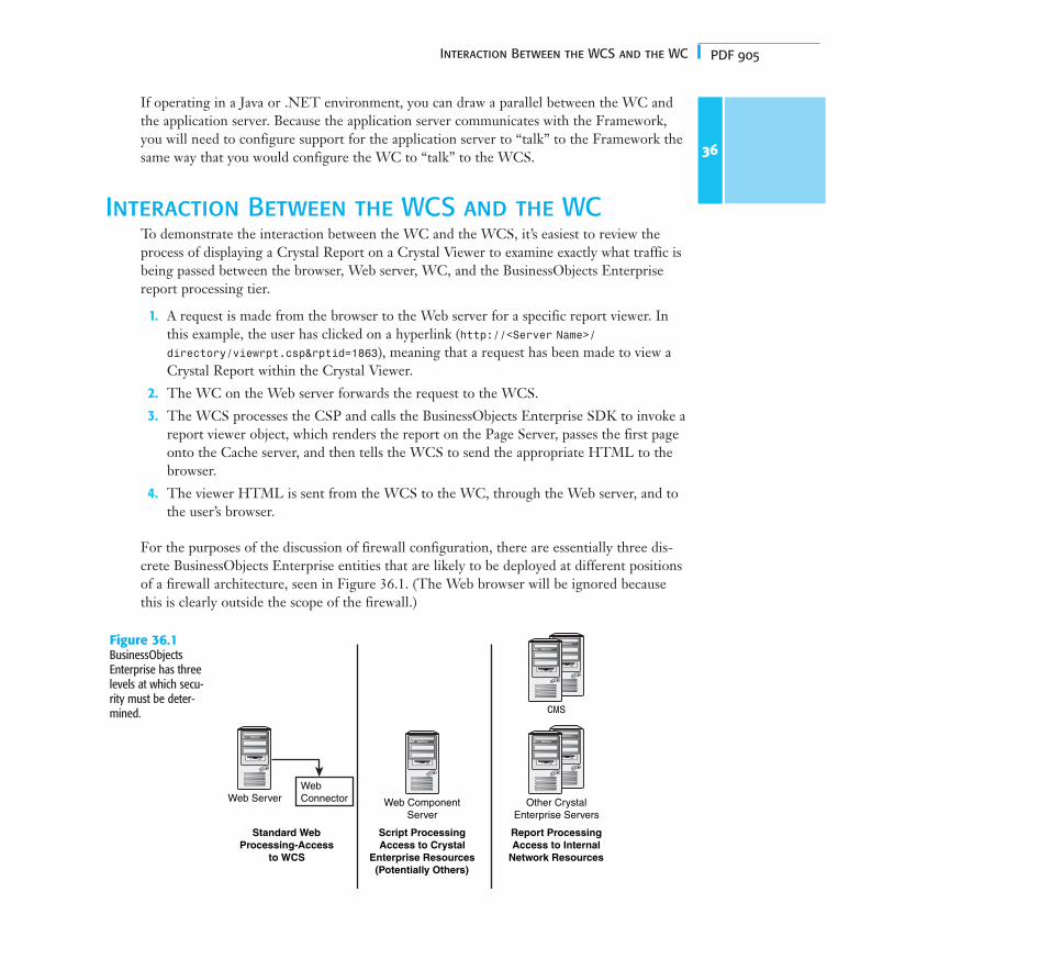
Interaction Between the WCS and the WCTo demonstrate the interaction between the WC and the WCS, it’s easiest to review theprocess of displaying a Crystal Report on a Crystal Viewer to examine exactly what traffic isbeing passed between the browser, Web server, WC, and the BusinessObjects Enterprisereport processing tier.
1. A request is made from the browser to the Web server for a specific report viewer. Inthis example, the user has clicked on a hyperlink (http://<Server Name>/
directory/viewrpt.csp&rptid=1863), meaning that a request has been made to view aCrystal Report within the Crystal Viewer.
2. The WC on the Web server forwards the request to the WCS.
3. The WCS processes the CSP and calls the BusinessObjects Enterprise SDK to invoke areport viewer object, which renders the report on the Page Server, passes the first pageonto the Cache server, and then tells the WCS to send the appropriate HTML to thebrowser.
4. The viewer HTML is sent from the WCS to the WC, through the Web server, and tothe user’s browser.
For the purposes of the discussion of firewall configuration, there are essentially three dis-crete BusinessObjects Enterprise entities that are likely to be deployed at different positionsof a firewall architecture, seen in Figure 36.1. (The Web browser will be ignored becausethis is clearly outside the scope of the firewall.)
36
Web ServerWebConnector
Standard WebProcessing-Access
to WCS
Web ComponentServer
Script ProcessingAccess to Crystal
Enterprise Resources(Potentially Others)
Other CrystalEnterprise Servers
Report ProcessingAccess to Internal
Network Resources
CMS
Figure 36.1BusinessObjectsEnterprise has threelevels at which secu-rity must be deter-mined.

PDF 906 Chapter 36 Deploying BusinessObjects Enterprise in a Complex Network Environment
Each of these entities is likely to require different levels of firewall protection determined bytheir closeness to the internal network.
In cases where you do not deploy a WCS (such as the Java, COM-SDK, and .NET scenar-ios) there are only two entities, however: the SDK running on the application server and theBusinessObjects Enterprise services or daemons.
As previously mentioned, the barriers that a secure system provides are commonly brokendown into distinct layers (with each layer defining a security measurement and effectivelydenoting an acceptable level of exposure). Each layer is identified by the communicationfrom one network to another network via a firewall. Then, a detailed example involvingBusinessObjects Enterprise communication through a firewall will be provided as well aswhat the appropriate system settings should be and how the communication will beaddressed at an IP/port level.
Figure 36.2 shows the most typical example of a firewall implementation. In this scenario,the browser-to-Web server communication is controlled through the standard firewall con-trol, allowing only HTTP requests to be forwarded through to the Web server on port 80(other services such as Telnet and mail might be permitted through other predefined portsas well). Clearly, BusinessObjects Enterprise is not involved at this stage of the firewall. Thisdoes, however, represent the entry point into the resources managed by the target environ-ment. From this point forward, internal network resources will be used; this interim envi-ronment is normally called the DMZ (or Demilitarized Zone). The DMZ, therefore, is anetwork added between a protected network and an external network.
36
Figure 36.2BusinessObjectsEnterprise can bedivided into tiers forfirewall deployment.
Web ServerWebConnectorBrowser Other Crystal
Enterprise Servers
Web ComponentServer
Firewall Firewall
DMZ InternalNetwork
The architecture of BusinessObjects Enterprise fits conveniently into this infrastructure.The separation of the WC from the WCS enables the WC to remain within the DMZalong with the Web server. Consequently, an additional firewall can easily be deployed to

PDF 907Interaction Between the WCS and the WC
protect the requests forwarded through the WCS—this, after all, will be communicatingdirectly to the other BusinessObjects Enterprise servers and is a component on the CrystaleBusiness Framework. Alternatively, the various application server deployments (Java,COM, or .NET) would also reside in the DMZ on the application server.
Because the WC and WCS allow for support of URL-level requests to support legacyBusinessObjects Enterprise applications, some enterprises choose not to implement the WCand WCS in an extranet environment. Instead the application-server deployment with theCE-SDK allows for application-level control of the interaction between the Web (application)server facilitating tighter security at this level. Please refer to Figure 36.3 for an illustration.
For instance, organizations might not desire any extranet access to the Crystal ManagementConsole (CMC). By not installing the WC and WCS in the extranet DMZ, no access to theCMC can occur from the extranet, perhaps alleviating security concerns in an extranet envi-ronment where malicious attacks are routine.
36
Figure 36.3This is how to configure a firewall in a non-WCS deployment.
Web ServerCE-SDK
Browser Other CrystalEnterprise ServersFirewall Firewall Firewall
DMZ InternalNetwork
Internal AdministrativeWeb Server
WC, WCS,Administrative Files
To examine the details of the communication of the WC to the WCS through the secondfirewall, the discussion will be broken down into two distinct portions: the initialization ofthe communication (a request for service), and servicing of the request after the communi-cation has been established. This two-stage nature of communication was detailed in theeBusiness Framework in an earlier section in this chapter.
Understanding Initial TCP/Port ProcessingWhen the Web server receives a BusinessObjects Enterprise resource request from a Webbrowser, it forwards the request to the WC or processes the request internally in the case ofthe SDK. For this example, assume that the Web server has an IP address of 10.55.222.241(see Figure 36.4).
Figure 36.4Browser requestinginformation from theWeb server.
Web Server
WebConnectorWeb
Browser
Web Server IP address: 10.55.222.241

PDF 908 Chapter 36 Deploying BusinessObjects Enterprise in a Complex Network Environment
The WC prepares to make a TCP connection to the WCS. A TCP connection request hasfour critical elements:
■ Destination IP address (where it’s going)
■ Destination port (at which port/socket the request will be expected)
■ Source IP (address of the sender, where to send return messages)
■ Source port (port the sender will be listening on for a response)
The destination portion of this communication is determined by settings entered in the WCconfiguration dialog box in the Crystal Configuration Manager.
When making up the destination information, the WC reads this information from thesesettings. Because this is the machine name of the WCS, the IP address of the WCS is deter-mined by network name resolution. The port destination takes less work—it’s simply thenumber as entered in this dialog box. By default, this port is 6401. The only requirement isthat this port number is the same as the WCS was set to use when the WCS started. Thesource portion of the requests are both determined by the Web server’s operating system.
The Source IP is the IP address of the machine sending the request—the Web server. ThisIP address is determined by a request to the operating system. The port is also chosen by anoperating system request. The WC asks for an available socket (or port) that is not in use.The operating system randomly chooses an unused socket. The WC begins temporarily lis-tening on this port for a response from the WCS as soon as the initialization request is sent.It will only accept a response from the IP address of the WCS—any other requests at thisport will be dropped. At this point, the TCP connection request is ready to be sent with thisinformation:
■ Source IP—IP address of the Web server machine as determined by a call to the oper-ating system.
■ Source port—Port deemed to be available by the operating system. This will be a portnumber higher than 1024.
■ Destination IP—IP address of WCS as determined by network name resolution.
■ Destination port—Port as entered into the WC Configuration dialog box in CrystalConfiguration Manager. This must match the configured port for the WCS.
Assuming that the WCS has an IP address of 10.55.222.242 and that the assigned port(retrieved by an operating system call) is 3333, for this example, the completed request willbe as follows (these are formatted as IP address:port):
■ Destination IP—10.55.222.242:6401
■ Source IP—10.55.222.241:3333
The WCS is constantly listening on its defined port for service requests (the default 6401 inyour example, though another port could be used for listening if configured to do so).
36

PDF 909Interaction Between the WCS and the WC
When the WCS receives the TCP Connection Request from the WC, it begins to form aresponse. The response will have the same four primary components that the request had—a source port and IP and a destination port and IP. Embedded in this response is the IOR ofthe WCS. The IOR of WCS contains the IP address of the WCS, as well as the port num-ber specified in the -requestport option.
36
If the option is not specified, a free port is picked up at random by the CORBA library byasking the operating system for an available port. At this point, the WCS responds to theWC to complete the TCP connection. This TCP connection response will have this infor-mation:
■ Source IP—IP address of the WCS as determined by a call to the operating system.
■ Source port—A random port number, as determined by making a call to the operatingsystem.
■ Destination IP—The IP address as read from the Source IP address in the TCPConnection Request received from the WC.
■ Destination port—The port as read from the source port in the TCP ConnectionRequest received from the WC.
Assuming a randomly generated source port of 2345, you’ll have the TCP connection con-firmation of the following:
■ Destination IP:port—10.55.222.241:3333
■ Source IP:port—10.55.222.242:2345
While the WCS has been building its confirmation response, the Web server machine hasbeen listening for the response on the chosen port.
The Web server/Connector will only accept packets from the IP to which it sent therequest—this is for security. In this example, the operating system of the Web servermachine has been listening on port 3333. When the TCP Connection Response/Confirmation is received, the OS of the Web server machine will determine whether it’sfrom the correct location. If it is from the correct IP, it will accept the data and completethe TCP connection. The IOR is embedded inside this request, and the operating systempasses it onto the WC for processing.
Now that all this work has been done to establish this connection, the WC immediatelycloses it. This was merely to establish that both client and server are up and running andaccepting connections. The WC also received the IOR of the WCS in this short
N O T EWhen in a Java environment, the web.xml file configures the port of choice. When in the.NET environment, the port that the SDK uses to connect to the various services is deter-mined by those services because no outgoing communication is necessary from theBusinessObjects Enterprise Framework to the .NET application server and CE-SDK.

PDF 910 Chapter 36 Deploying BusinessObjects Enterprise in a Complex Network Environment
connection. The listening port on the WCS resumes listening to other clients, and the workof sending IP packets back and forth will be done on a second TCP connection.
Understanding Secondary TCP/Port ProcessingIt is in establishing the second TCP connection that BusinessObjects Enterprise works dif-ferently from most TCP/IP applications. The WC reads the IOR of the WCS and acquiresthe IP address and port number from it. Using this port number and IP address a secondconnection is made—one that will be used for actually transferring the data. (A straightTCP/IP application doesn’t have an IOR from which to read the IP and port of the server.It uses the source IP and port from the TCP connection confirmation to establish this sec-ond connection.) The BusinessObjects Enterprise application uses the information in theIOR and discards the source IP and port from the TCP connection confirmation.
Continuing your example, upon reading the port and IP information from the IOR of theWCS, the WC initiates a second TCP connection. This request will use this information:
■ Destination IP—The IP address of the WCS as reported in the IOR.
■ Destination port—The port number to be used for communication as reported in theIOR. If the -requestport directive is used, it will be that port; otherwise, it will be arandomly generated port number (you will use this).
■ Source IP—The IP address of the Web server.
■ Source port—The port on the Web server to be used for this connection. This isdetermined by asking the operating system for an available port.
In this example, assume that the randomly generated destination port number is 2345 andthe generated source port is 1061. You’ll have the TCP connection confirmation of the fol-lowing:
■ Destination IP:port—10.55.222.242:4000
■ Source IP:port—10.55.222.241:1061
When the WCS receives this request, it will respond to the WC to complete the connec-tion. The address to which it will send this connection is 10.55.222.241:1061. This destina-tion and port was determined by reading the source information of the incoming TCPconnection request. This is where the WCS’s connection response gets its destination. Asdemonstrated in the following list, this is really just the reversal of the information receivedfrom the WC. Completing your example, therefore, the WCS will communicate as follows:
■ Destination IP:port—10.55.222.241:1061
■ Source IP:port—10.55.222.242:4000
After the Web server/Connector machine receives the TCP connection response from theWCS, it is able to complete the TCP connection. Now that the TCP connection is made,IP packets will be sent back and forth on this channel. IP datagrams will be forwarded backand forth from the Web server (10.55.222.241:1061) to the WCS (10.55.222.242:4000), and
36

PDF 911Deploying BusinessObjects Enterprise with an IP Packet Filtering Firewall
vice versa, on these ports. The secondary connection, therefore, is the one that does nearlyall the data transference.
Now that you have seen exactly how the IP/port allocation is determined in theBusinessObjects Enterprise environment, you can look at a fully worked example applying aspecific firewall technology. Initially, you will look at packet filtering and then apply NATon top of this. Then this chapter briefly discusses how BusinessObjects Enterprise would fitin with the application of a Proxy Server (Socks) firewall.
Deploying BusinessObjects Enterprise with an IP Packet Filtering Firewall
Earlier this chapter noted that IP Filter firewalls restrict network traffic based on IP addressand port number. BusinessObjects Enterprise works well with IP Filter firewalls with theproviso that the IP address and TCP port number used by the servers are predetermined.This section discusses a scenario where the BusinessObjects Enterprise WC/Web server andWCS has one IP Filter between the two of them and the WCS is separated from the rest ofthe BusinessObjects Enterprise servers by a second firewall. In other words, it’s the commonfirewall scenario you looked at in the previous section. This is illustrated in Figure 36.5.
36
Figure 36.5IP Filtering—firewalldefinition.
CMS
Other CEServers
Network A
WCS
Network B Network C
IPFilter
Firewall
IPFilter
Firewall
Web Server
WebConnector
Let’s look at two distinct parts of communication across the networks: first, the most exter-nal portion (that is, between Network C and Network B), and second, the communicationbetween the WCS and the other BusinessObjects Enterprise servers—the internal portionbetween Network B and Network A (see Figure 36.6).
WCS
Network B Network C
IPFilter
Firewall
Web ServerWebConnector
Figure 36.6Configuration with IPFiltering—external firewall.

PDF 912 Chapter 36 Deploying BusinessObjects Enterprise in a Complex Network Environment
An External Packet Filtering Firewall ScenarioAny requests of the WC machine would follow the same steps as described in the previoussection. Initially, the WC would have to establish a TCP connection to the WCS. The WCwould initiate this handshake communication. The IP Filter firewall would certainly standto convolute this communication:
■ Destination IP—The IP of the WCS as determined by network name resolution. Thelookup would occur on the side of the Web server—usually by a DNS server in thiszone.
■ Destination port—The port to use for this communication is taken from theRegistry—it’s the value as entered in the WC Configuration dialog box in the CrystalConfiguration Manager. By default, this is port 6401.
■ Source IP:port—The IP:port of the Web server/WC machine as determined by a callto the operating system.
The network rules of this side of the firewall will quickly determine that the destination IPof this request will have to go through the firewall. Therefore, the network forwards thisTCP connection request to the firewall. The firewall then evaluates the information withinthe request—the destination port and IP address, as well as the source IP and source port.The firewall must have rules that allow this connection to go through—it must acceptrequests for the WCS’s IP from the WC’s IP and the request must be on the specified port.At this point in the request, the firewall will have to allow traffic through it that follows thisconfiguration:
■ Source IP—The IP of the WC/Web server
■ Source port—Any
■ Destination IP—The IP of the WCS
■ Destination port—6401 (or whichever is the WCS’s listening port)
■ Action—Accept
When the WCS receives this request, it must respond to it. It garners the information aboutwhere to respond from the information within the request. It takes the Source IP and Portand makes this the destination. Because this is a random port, the firewall must be config-ured to allow any ports to leave Network B and go to Network C. This is a generallyaccepted practice—strict port enforcement is done at the bastion host. Therefore, thefirewall rules to complete this request should resemble the following:
■ Source IP—Any IP from Network B
■ Source port—Any
■ Destination IP—Any IP outside the network
■ Destination port—Any
■ Action—Accept
36

PDF 913Deploying BusinessObjects Enterprise with an IP Packet Filtering Firewall
When the connection request gets through the firewall, the network resolution will deter-mine that the destination is in Network C. The request will hit the Web server/WC. At thispoint, there is a TCP connection between the two machines, going through the firewall.The WCS will send the WC its IOR and the WC will close this TCP connection.
The IOR contains the IP and port on which the second connection will be made. The portnumber in the IOR will be one of many values depending on the existence or nonexistenceof the -requestport xxxx directive on the WCS’s command line. If there is a -requestport,this is the value that will be in the IOR. If there isn’t, it will be a random port as chosen bythe WCS’s operating system. Generally, a random port is not acceptable because administra-tors won’t enable their firewall rules to accept any ports from a specific IP.
36
When this second connection is made, the -requestport directive should be set to a fixedport number and this port number should be accepted if the IP is from the Webserver/Connector machine. This second TCP connection information will look like this:
■ Destination IP—The IP of the WCS as read from the IOR.
■ Destination port—The port as read from the IOR, the recommendation being to usethe -requestport directive to define this value.
■ Source IP—The IP of the Web server/WC machine as determined by a call to theoperating system.
■ Source port—The free port as returned by a request to the operating system.
The firewall will evaluate this request and the port will have to be open. As an example, ifthe -requestport directive uses port 3333, the firewall rules will have to look like this:
■ Source IP—The IP of the WC/Web server
■ Source port—Any
■ Destination—The IP of the WCS
■ Destination port—3333 (or whichever is used with -requestport directive)
■ Action—Accept
The WCS will respond to this request on whichever port the Web server/WC found to beavailable. This will be allowed through the firewall because any port is allowed from the internal network to the external. There will then be an established connection betweenthe WCS and the WC, and IP packets will be sent on this channel. The configuration ofthe firewall rules for an IP Filter firewall between a WCS and WC are summarized in Table 36.1.
N O T EThe BusinessObjects Enterprise Administrator’s Guide suggests that the use of the -requestport option is required with IP Filter firewalls.

PDF 914 Chapter 36 Deploying BusinessObjects Enterprise in a Complex Network Environment
Table 36.1 Firewall Configuration Rules
Source Destination Port Action
Network B Any Any Accept
IP of WC IP of WCS 6401, -requestport Accept
Network C Any Any Reject
36
An Internal Packet Filtering Firewall ScenarioThere are several servers in the BusinessObjects Enterprise environment with which theWCS communicates. It must communicate with the CMS as part of logon/security proce-dures, while the Cache Server will also be involved in a communication with the WCS forreport viewing requests. (Additionally, the WCS will communicate with the Input FileRepository Server, where the report objects are maintained when the thumbnail of a reportis displayed on the web page.) Obviously, traffic to each of these servers from the WCS willhave to be allowed by the IP Filter firewall (see Figure 36.7).
N O T EWhen the WCS is started with the -requestport switch, this port will have to be opengoing from Network B to Network C for the IP of the WCS.
Figure 36.7Configuring an IPFiltering—internal firewall.
WCS
Network B Network C
IPFilter
Firewall
Web ServerWebConnector
First and foremost, the WCS will have to communicate with the CMS. The CMS providesthe Name Service in the BusinessObjects Enterprise environment. Without this service, theWCS will not be able to communicate with any of the servers. The CMS listens forrequests on the port designated, shown in Figure 36.8 under the configuration tab in theCrystal Configuration Manager (the default value for this port is 6400).
Whenever the WCS needs to communicate with the Name Service of the CMS, it does soon port 6400 by default. The first time the WCS has to communicate with the NameService is when it starts. When the WCS starts, it must register itself with the NameService as part of its initialization process. This communication occurs on port 6400. ATCP connection occurs between the WCS and CMS for this to happen. The request willhave the following information in it:
■ Destination IP—The IP of the CMS as determined by network name resolution.
■ Destination port—The port number of the CMS as defined in the SERVICES file.

PDF 915Deploying BusinessObjects Enterprise with an IP Packet Filtering Firewall
■ Source IP—The IP of the WCS as determined by a call to the OS of the WCS.
■ Source port—A random available port as determined by a call to the OS of the WCS.
36Figure 36.8This screenshows CMS
port configuration.
After the CMS receives this TCP connection request, it responds back to the WCS to com-plete the initial connection. This connection response contains the following information:
■ Destination IP—The IP of the WCS as determined by reading the Source IP fromthe TCP connection request.
■ Destination port—The port the WCS is using as determined by reading the SourcePort from the TCP connection request.
■ Source IP—The IP of the CMS as determined by a call to the OS of the CMS.
■ Source port—A random port as determined by a call to the OS of the CMS.
After this initial connection is complete, the CMS sends the WCS its IOR. The WCS thencloses the initial connection and establishes a connection to the CMS using the IP and portthat is in the IOR. If the CMS is using the -requestport directive, this is the port that theWCS will use to initiate communication with the CMS. This second connection requestwill contain this information:
■ Source IP—The IP of the WCS as determined by a call to the OS of the WCS.
■ Source port—The port number of the WCS as determined by a call to the OS of the WCS.
■ Destination IP—The IP of the CMS as read from the IOR that the CMS sent to theWCS in the initial connection.
■ Destination port—The port the CMS put in the IOR. If using the -requestportdirective, this is the port the CMS put in the IOR. Otherwise, it will be a port deemedavailable as per a request to the OS of the CMS.

PDF 916 Chapter 36 Deploying BusinessObjects Enterprise in a Complex Network Environment
The CMS responds to this request to complete the connection. This response contains thefollowing information:
■ Source IP—The IP of the CMS as determined by a call to the OS.
■ Source port—A free port on the CMS as determined by a call to the OS of the CMS.
■ Destination IP—The IP of the WCS as read from the Source IP of the connectionrequest.
■ Destination port—The port being used by the WCS as read from the Source Port ofthe connection request.
When this connection is complete, the WCS and CMS will hold it open and use it when-ever communication between the two is required. From a firewall configuration perspective,two ports are involved in the communication between the CMS and the WCS: first, theport the CMS listens on—this is port 6400 by default—and second, the port that is estab-lished as the main communication channel between these two processes—this should be thevalue as defined by the -requestport directive. The “rules” for the firewall configurationcan be defined as shown in Table 36.2.
Table 36.2 Firewall Configurations Rules (Network A to Network B)
Source Destination Port Action
Network A Any Any Accept
WCS CMS 6400, -requestport* Accept
Network B Any Any Reject
36
N O T EWhen the CMS is started with the -requestport switch, this port will have to be opengoing from Network B to Network A for the IP of the WCS.
However, this is only one of three servers with which the WCS would need to communi-cate. Requests to the Input FRS and Cache Server would still need to be allowed throughthe firewall. The standard practice is when servers need to communicate with one another,they ask the Name Service for a copy of the IOR of the server they need to contact. Tocommunicate with either the Input FRS or the Cache Server, therefore, the WCS needs toask the CMS for information about the server to which it needs access.
When these servers start, they give the Name Service portion of the CMS a copy of theirIOR. As the other servers require access to it, they ask the CMS for a copy of the IOR ofthe server they need information about. To determine the IOR of a given server, the WCSand CMS collaborate. When the WCS has a copy of the IOR of the particular server, itattempts to make a connection to the server using the information in the IOR. The infor-mation in the IOR contains both the IP address and the port to be used for communication

PDF 917Exploring the NAT and BusinessObjects Enterprise Relationship
and security information. If the -requestport directive is used, the port will be that definedport; otherwise, it’s a random port. When working with firewalls, the preferred method is touse -requestport so you can control on which port traffic will be allowed in. As a conclu-sion, therefore, the firewall rules between Network B and Network A would need to be setup as shown in Table 36.3.
Table 36.3 Firewall Configuration Rules (Network B to Network A)
Source Destination Port Action
Network A Any Any Accept
IP of WCS IP of CMS 6400, -requestport for each of the servers Accept(CMS, Input FRS, Cache Server)
Network B Any Any Reject
The use of NAT within the IP Filtering firewall adds an additional level of complexity,something explored in the next section.
Using BusinessObjects Enterprise with NATNAT takes IP Filtering one level further by masking the IP address of the internal serverwhen its packet gets through the firewall. NAT makes it appear as if all traffic from insidethe network comes from a different IP address. NAT hides internal IP addresses by convert-ing all internal host addresses to the address of the firewall as packets are routed through thefirewall. The firewall then retransmits the data payload of the internal host from its ownaddress using a translation table to keep track of which ports/sockets on the exterior inter-face equate to which ports/sockets on the interior interface.
Exploring the NAT and Crystal EnterpriseRelationship
It has been established that within BusinessObjects Enterprise, server-to-server communica-tion takes the single TCP connection approach one step further. A second TCP connectionis made when servers communicate in BusinessObjects Enterprise (listen on one, communi-cate on another). When it comes to firewalls, it is important to recognize that two portsneed to be open.
However, with translated IP addresses in the NAT instance, there is an additional concernbecause it is the IOR that tells the servers which IP to use; this is not directly retrieved fromthe packets themselves. This section explains what is required to make BusinessObjectsEnterprise work with a NAT firewall—the WC and WCS communication as an example.
When the WC communicates to the Web server, it is on the outside of the firewall. This ishow it will be in most configurations and the assumption made during this chapter. TheWC/Web server will reside in a DMZ and the rest of the servers inside the corporate
36

PDF 918 Chapter 36 Deploying BusinessObjects Enterprise in a Complex Network Environment
network. As before, when the WC needs to communicate with the WCS, it will send a TCPConnection request. To get there, it will need to resolve the name of the WCS machine.Because the WCS is inside the firewall, this can potentially create a problem with a NATfirewall. As you saw with the Telnet example in the previous section, generally the incomingrules for NAT firewalls only accept packets with destination IPs going to the firewall.
In the Telnet example, the client was inside the firewall and the outbound firewall rulesallowed all IP destinations outside the wall, as well as any port (this is normal). The NATfirewall then altered the packet and sent it onto the Telnet server. The Telnet serverresponded back to the firewall. The firewall was expecting the response and allowed itthrough because it was expected. The NAT firewall altered the destination of this responseback to the internal private IP of the Telnet client and routed it onto the Telnet clientmachine.
In BusinessObjects Enterprise, the WC needs to send the initial TCP Connection requestto the WCS. This is somewhat different from the Telnet application because the machine inthe external network (the WC) is initializing the communication instead of the machineinside the network. Because the request didn’t originate inside the firewall, the firewall isn’texpecting any communication. When the WC resolves the machine name of the WCS to anIP address, this won’t always be the IP as it exists on the internal network in a NAT envi-ronment. There are a number of options available where the features of NAT firewalls couldbe configured to work in this situation:
■ The NAT firewall could be configured to allow packets whose destination is the fire-wall.
■ The NAT firewall could be configured to allow packets whose destination is inside thefirewall and have rules on which of these are allowed.
■ The NAT firewall could use a group of IP addresses in the external network that eachrepresents one IP address in the internal network.
There is still one outstanding question, however: To which IP address should the request besent? BusinessObjects Enterprise requires that the machine on the outside of the firewall beable to send packets to the private IP address of the WCS. It might be possible to get awaywith not using the private IP address for the initial connection; if the initial connectionrequest was sent to a statically mapped IP address or to the IP address of the firewall itself,the firewall could inspect its destination and forward it on without issue.
Remember that the data that is sent in the initial connection from the WCS to the WC isthe IOR of the WCS. The IOR contains the IP address and the port of the WCS.Moreover, this is the internal IP address of the WCS—it is not the address of the firewall ora static IP address of the firewall that is mapped to the internal IP address. To allow thistraffic through, therefore, on a NAT firewall, the rule that needs to be in place for WC toWCS communication is that the packets to the internal IP address must be allowed throughthe firewall. (This might, of course, require further rules to route these packets on the firewall.)
36

PDF 919BusinessObjects Enterprise and Proxy Servers
The ports that are allowed through can be narrowed, of course. The destination port onwhich the WCS is listening and its request port need to be allowed through the firewall. Inthe end, the firewall rules with a NAT firewall are pretty much in line with what the firewallrules are on an IP Filter firewall. For example, Table 36.4 assumes the WCS is inside thenetwork and the WC is external to the network.
Table 36.4 Firewall Configuration Rules (WCS Internal and WC External)
Source Destination Port Action
Internal IP of WCS External IP of WC Any Accept
External IP of WC Internal IP of WCS WCS listening port (6401 by Acceptdefault), -requestport
External Network Internal Network Any Reject
If packets from the hosts on the external network sent to the internal IOP addresses arerouted to the firewall and the firewall accepts the packets, the connection will be establishedsuccessfully. Given that in many cases the external network is a DMZ and the firewall is arouter on the LAN, this configuration is possible by adding static routes on the hosts in theDMZ to the firewall. Depending on network configuration, even static routes on the hostswon’t be necessary if the firewall between the internal network and DMZ is the defaultroute for all traffic.
BusinessObjects Enterprise and Proxy Servers It is not the intention at this stage in the book to investigate how BusinessObjectsEnterprise can be configured to work with proxy servers in any great detail. This is coveredin some depth in the Administrator’s guide that accompanies BusinessObjects Enterprise.However, some sample Socks configurations will be shown and there will be a brief discus-sion as to how BusinessObjects Enterprise would operate effectively with each configura-tion.
Socks settings for each of the BusinessObjects Enterprise servers are defined using theCrystal Configuration Manager (through the Connection tab).
Socks—The WC and WCSFigure 36.9 illustrates the operation of Socks between the WC and the WCS.
Given this scenario, the Socks setting through the Crystal Configuration Manager should bethe following:
■ On WC, specify the Socks server at the WCS Configuration tab.
■ On CMS, specify the Socks server at the Connection tab.
Access control rules on the Socks server should be set to something similar to that shown inTable 36.5.
36

PDF 920 Chapter 36 Deploying BusinessObjects Enterprise in a Complex Network Environment
Table 36.5 Socks Configuration (WC to WCS)
Source Destination Port Action
WC WCS 6401 -requestport Accept
Otherwise Reject
There are a couple of points worth noting:
■ Although the WC connects to WCS, the Socks server information is set up on CMS rather than on WCS. This is because the WCS will obtain the Socks setting from CMS.
■ The initialization from WC to WCS port 6401 uses the host name for the WCS in theSocks request. Therefore, the Socks server must be able to resolve the host name forWCS. For example, if the WC and WCS use NetBIOS names and the Socks server is aUnix box that doesn’t support NetBIOS names, it is necessary to ensure the Socksserver can resolve the same name as specified by the WC; that is, by using a local host’s file.
Firewall Configuration: Socks—WCS and CMSFigure 36.10 illustrates the operation of Socks between the WCS and the CMS.
In this instance, the Socks setting at Crystal Configuration manager should be the following:
■ On WCS, specify the Socks server at the CMS Configuration tab.
■ On CMS, specify the Socks server at the Connection tab.
36
Figure 36.9Socks configuration—WC to WCS.
WCS
CMS
File ServerPage ServerJob Server
Cache Server Socks Server
Web ConnectorFirewall

PDF 921BusinessObjects Enterprise and Proxy Servers
Access control rules on the Socks server should be set to something similar to that shown inTable 36.6.
Table 36.6 Socks Configuration (WCS to CMS)
Source Destination Port Action
WCS CMS 6400 -requestport Accept
WCS Other Enterprise Servers Default ports -requestports Accept
Otherwise Reject
Please note that when WCS makes the initial connection to CMS on port 6400, it will passthe host name to the Socks server. Thus, the Socks server must resolve the CMS hostname.
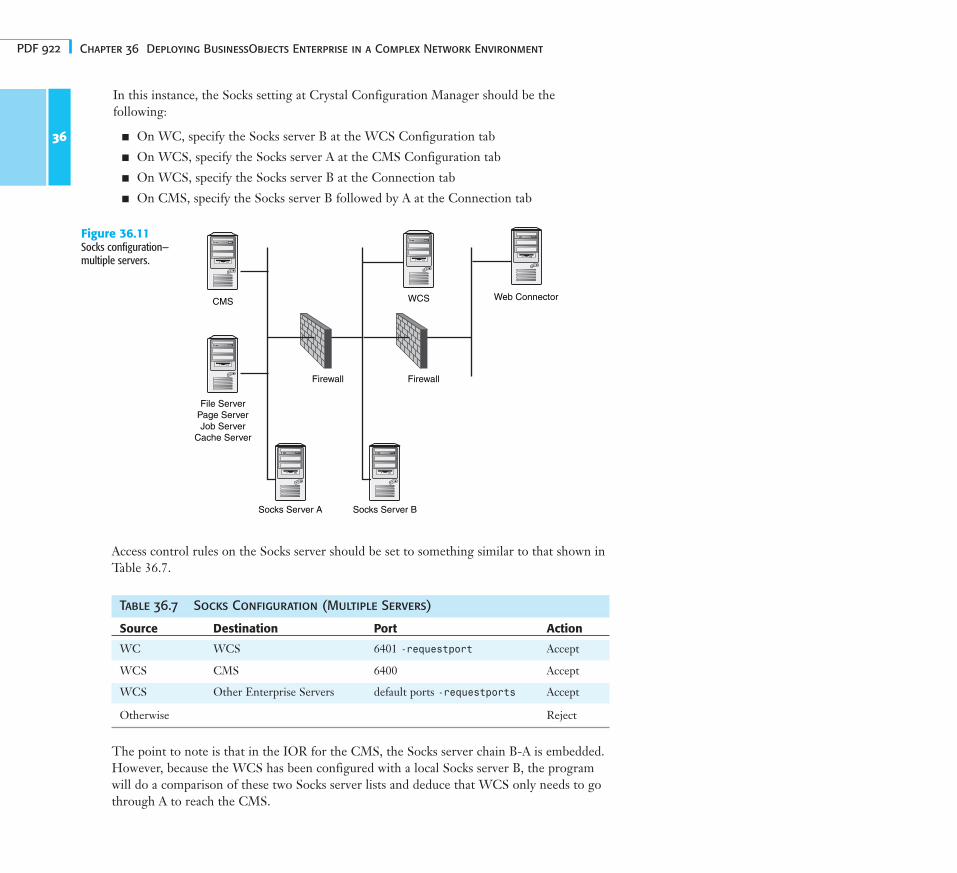
Socks—Multiple BusinessObjects Enterprise ServersFigure 36.11 illustrates the operation of Socks between multiple servers in theBusinessObjects Enterprise environment.
When multiple Socks servers are deployed in the network, the BusinessObjects EnterpriseSocks setup can facilitate the traversal of them. However, due care and attention should betaken in how the Socks servers are placed and traversed. In general, the BusinessObjectsEnterprise servers see these Socks servers as a chain, and the setup in the Crystal ConsoleManager should specify how to traverse them from the outermost to the innermost link.
36
Figure 36.10Socks configuration—WCS to CMS.
CMS
File ServerPage ServerJob Server
Cache Server Socks Server
Web Connector
WCS
Firewall
PDF 922 Chapter 36 Deploying BusinessObjects Enterprise in a Complex Network Environment
Access control rules on the Socks server should be set to something similar to that shown inTable 36.7.
Table 36.7 Socks Configuration (Multiple Servers)
Source Destination Port Action
WC WCS 6401 -requestport Accept
WCS CMS 6400 Accept
WCS Other Enterprise Servers default ports -requestports Accept
Otherwise Reject
The point to note is that in the IOR for the CMS, the Socks server chain B-A is embedded.However, because the WCS has been configured with a local Socks server B, the programwill do a comparison of these two Socks server lists and deduce that WCS only needs to gothrough A to reach the CMS.
36
Figure 36.11Socks configuration—multiple servers.
CMS
File ServerPage ServerJob Server
Cache Server
Socks Server A Socks Server B
Web ConnectorWCS
Firewall Firewall
In this instance, the Socks setting at Crystal Configuration Manager should be the following:
■ On WC, specify the Socks server B at the WCS Configuration tab
■ On WCS, specify the Socks server A at the CMS Configuration tab
■ On WCS, specify the Socks server B at the Connection tab
■ On CMS, specify the Socks server B followed by A at the Connection tab