
DEPARTMENT OF MECHANICAL ENGINEERING...
24
DEPARTMENT OF MECHANICAL ENGINEERING UNIVERSITY OF BAHRAIN MEG373 Kinematics and Dynamics of Machines Introduction to Mechanisms What is a Mechanism ? A mechanism is a machine composed of rigid members that are jointed together. The members interact with one another by virtue of the joints. The joints are formed by portions of the surfaces of the members joined that contact one another. The geometries of the contacting surface segments determine the properties of each joint. Mechanisms may be simple or complex. Figure 1.1 shows a foot pup mechanism as an example of a simple mechanism. The design of mechanisms is a technical area that is unique to mechanical engineering. Its history stretches back to prehistoric times. Artisans such as blacksmiths and carpenters also functioned as the designers of mechanisms. One of the original functions of engineers was the design of mechanisms both for warfare and for peaceful uses. In Renaissance times, we find Leonardo da Vinci depicting a sophisticated variety of mechanisms, mostly for military purposes. Sometime thereafter the distinction between civil engineering and military engineering appeared. The modern era in mechanism design, along with the history of mechanical engineering as a distinct discipline, can be viewed as starting with James Watt. Figure 1 That is not to say that the subject has remained static. In fact, there have been dramatic changes in the practice of mechanism design in recent years. Traditionally, machines have been designed to be powered by a single "prime mover," with all functions mechanically coordinated. That tradition certainly predates Watt. Recent developments in computer technology, coupled with improvements in electric motors and other actuators, have made it possible to use a different approach. This is an approach in which machines are powered by multiple actuators coordinated electronically. The resulting machines are simpler, less expensive, more easily maintained, and more reliable. Another major change is in the techniques used in mechanism design. The use of interactive computer graphics has had a dramatic impact on design practice. One of our motivations in producing this book, even when a number of excellent texts are already available in mechanism kinematics, is to Dr. Mostafa S. Habib MEG 373 Kinematics and Dynamics of Machines 1/24
Transcript of DEPARTMENT OF MECHANICAL ENGINEERING...
DEPARTMENT OF MECHANICAL ENGINEERING UNIVERSITY OF BAHRAIN
MEG373 Kinematics and Dynamics of Machines Introduction to Mechanisms
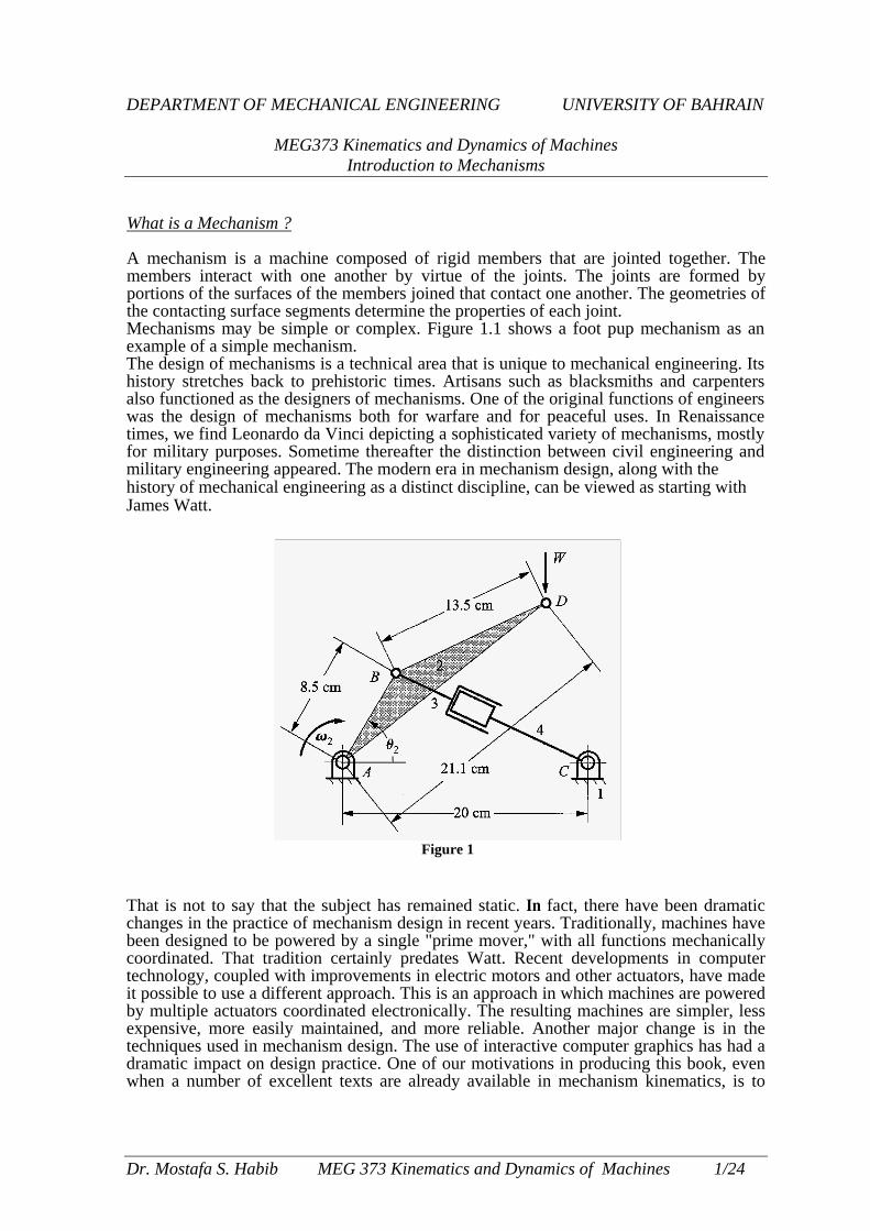
What is a Mechanism ? A mechanism is a machine composed of rigid members that are jointed together. The members interact with one another by virtue of the joints. The joints are formed by portions of the surfaces of the members joined that contact one another. The geometries of the contacting surface segments determine the properties of each joint. Mechanisms may be simple or complex. Figure 1.1 shows a foot pup mechanism as an example of a simple mechanism. The design of mechanisms is a technical area that is unique to mechanical engineering. Its history stretches back to prehistoric times. Artisans such as blacksmiths and carpenters also functioned as the designers of mechanisms. One of the original functions of engineers was the design of mechanisms both for warfare and for peaceful uses. In Renaissance times, we find Leonardo da Vinci depicting a sophisticated variety of mechanisms, mostly for military purposes. Sometime thereafter the distinction between civil engineering and military engineering appeared. The modern era in mechanism design, along with the history of mechanical engineering as a distinct discipline, can be viewed as starting with James Watt. That is not to say tchanges in the practbeen designed to becoordinated. That ttechnology, coupledit possible to use a dby multiple actuatorexpensive, more eatechniques used in mdramatic impact on when a number of
Dr. Mostafa S. Habi
Figure 1
hat the subject has remained static. In fact, there have been dramatic ice of mechanism design in recent years. Traditionally, machines have powered by a single "prime mover," with all functions mechanically radition certainly predates Watt. Recent developments in computer with improvements in electric motors and other actuators, have made ifferent approach. This is an approach in which machines are powered s coordinated electronically. The resulting machines are simpler, less sily maintained, and more reliable. Another major change is in the echanism design. The use of interactive computer graphics has had a
design practice. One of our motivations in producing this book, even excellent texts are already available in mechanism kinematics, is to
b MEG 373 Kinematics and Dynamics of Machines 1/24
provide a treatment that reflects these changes in practice. Kinematics is the study of position and its time derivatives. Specifically, we are concerned with the positions, velocities, and accelerations of points and with the angular positions, angular velocities, and angular accelerations of solid bodies. Together these entities are sufficient to describe the motions of solid bodies. The position of a body can be defined by the position of a nominated point of that body combined with the angular position of the body. In some circumstances we are also interested in the higher time derivatives of position and angular position. The subject of kinematics is a study of the geometry of motion. This is an accurate title because kinematics is geometry with the element of time added. The bulk of the subject matter of this book is often referred to as the kinematics of mechanisms. Our objective is to present techniques that can be used to design mechanisms to meet specific motion requirements. That is why the subject matter is approached from a mechanical designer's perspective. Analysis and Synthesis of Mechanisms
The material in this book falls into two classifications. The first consists of techniques to determine the positions, velocities, and accelerations of points in the members ofmecha-nisms and the angular positions, velocities, and accelerations of those members. These are kinematic analysis techniques. The second type of material comprises methods for mathe-matically determining the geometry of a mechanism to produce a desired set of positions and/or velocities or accelerations. These are rational synthesis techniques. The activity that distinguishes engineering from science is design. Science is the study of what is; engineering is the creation of what is to be. This creative activity is design or, more formally, synthesis. The rational synthesis techniques developed by kinematicians offer a rather direct route to mechanism design that lends itself well to automation using computer graphics workstations. However, these techniques do not represent the only way to design mechanisms and they are relatively restrictive: Rational synthesis techniques exist only for specific types of mechanism design problems, and many practical mechanism design problems do not fit within the available class of solutions. An alternative is to use informal synthesis. This is a methodology used by engineers to solve design problems in many technical areas, not just in mechanism design. The basic procedure is to "guess" a set of dimensions and then use analysis to check the resulting performance. The dimensions are then adjusted to attempt to match more closely the performance specifications, and the mechanism is analyzed again. The process is repeated until an acceptably close match to the specifications is achieved. Thus, a primary use of the analysis material is also in mechanism design.
From an engineering point of view, it is not possible to treat mechanism design solely in terms of kinematics. The motivation for performing an acceleration analysis is often to enable inertia forces on the links to be calculated, allowing, in turn, computation of the forces transferred between links and the internal forces, or stresses, within the links. Mechanisms must usually drive loads, as well as generate motions. Of course, as soon as we introduce the concept of force, we leave the domain of pure kinematics and enter that of kinetics. Insofar as the largest forces in many mechanisms are inertia forces created by motion, it is convenient to study them within the general framework of kinematic tech-niques. There is also an important symmetry between the geometry of the force distribution and that of the velocity distribution that is particularly useful when working with spatial mechanisms. Thus, it is entirely appropriate to treat mechanism statics or kinetics within the general geometry of motion framework constructed to study mechanism kinematics. Such a treatment is presented in the later chapters ofthis book. Mechanisms are assemblages of rigid members connected together by joints. Mechanisms transfer motion and mechanical work from one or more actuators to one or more "output" members. For the purposes of kinematic design, we idealize a mechanism to a kinematic linkage in which all the members are assumed to be perfectly rigid and are connected by kinematic joints. A kinematic joint is formed by direct contact between the surfaces of two
Dr. Mostafa S. Habib MEG 373 Kinematics and Dynamics of Machines 2/24
members. One of the earliest codifications of mechanism kinematics was that of Reuleaux (1876),1 and some of the basic terminology we use originated with him. He called a kine-matic joint a "pair." He further divided joints into "lower pairs" and "higher pairs." A lower pair joint is one in which contact between two rigid members occurs at every point of one or more surface segments. A higher pair is one in which contact occurs only at isolated points or along line segments. All other things being equal, a higher pair will produce higher contact stresses than will a lower pair.
Joints are the most important aspect of a mechanism to examine during an analysis. They permit relative motion in some directions while constraining motion in others. The types of motion permitted are related to the number of degrees of freedom (dot) ofthe joint. The number of degrees of freedom of the joint is equal to the number of independent coordinates needed to specify uniquely the position of one link relative to the other constrained by the joint.
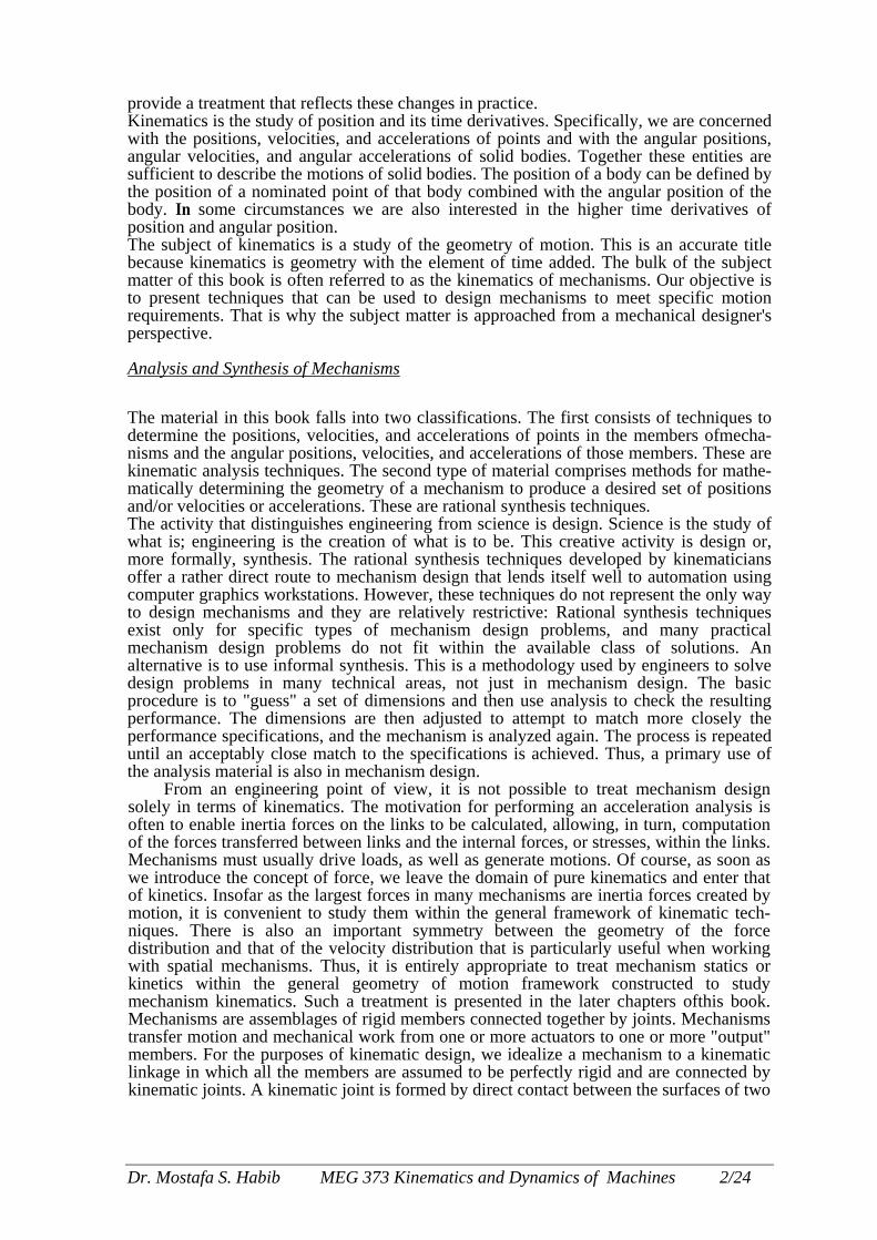
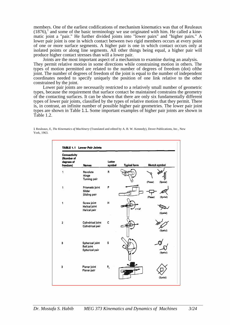
Lower pair joints are necessarily restricted to a relatively small number of geometric types, because the requirement that surface contact be maintained constrains the geometry of the contacting surfaces. It can be shown that there are only six fundamentally different types of lower pair joints, classified by the types of relative motion that they permit. There is, in contrast, an infinite number of possible higher pair geometries. The lower pair joint types are shown in Table 1.1. Some important examples of higher pair joints are shown in Table 1.2.
1 Reuleaux, E, The Kinematics of Machinery (Translated and edited by A. B. W. Kennedy), Dover Publications, Inc., New York, 1963.
Dr. Mostaf
a S. Habib MEG 373 Kinematics and Dynamics of Machines 3/24
Lower pair joints are frequently used in mechanism design practice, They give good service because wear is spread out over the contact surface and because the narrow clearance between the surfaces provides good conditions for lubrication and a tight constraint on the motion. Changes in the geometric properties of the joint with wear occur slowly for a lower pair. At least as important are the simple geometries of the relative motions that these joints permit.
Higher pair joints that involve pure rolling contact, or that approximate that condition, are also used frequently. In pure rolling contact, the points in one of the two joint surfaces that are actually in contact with the other surface at any instant are at rest relative to that surface. Hence there is no relative sliding of the surfaces and joint friction and wear are minimized. Physically, the limitation of this kind of joint is the stress intensity that the material of the contacting bodies can support. Stresses are necessarily high because of the very small
bbapjiT
D
contact areas. If the bodies were perfectly rigid, contact would occur only at discrete points or along a line, the contact area would be zero, and the stresses would be locally infinite!
Lower pair joints such as revolute joints and cylindrical joints are also often simulated by systems such as all or roller bearings in which there are actually many elements acting in parallel. The actual contact joints in a all bearing are rolling contacts, which are higher pairs. In this way, the low-friction properties of rolling contacts re exploited to obtain a joint with lower friction and higher load and relative speed capabilities than would be ossible with a plain revolute joint. At the same time, the simple overall relative motion geometry of the revolute oint is retained. This is one example of a compound joint in which the joint is actually a complex mechanism but s regarded as kinematically equivalent to a simple revolute. Several examples of compound joints are shown in able 1.3.
Conversely, higher pairs are sometimes replaced by equivalent lower pair joints (Fig. 1.2). For example, a
r. Mostafa S. Habib MEG 373 Kinematics and Dynamics of Machines 4/24
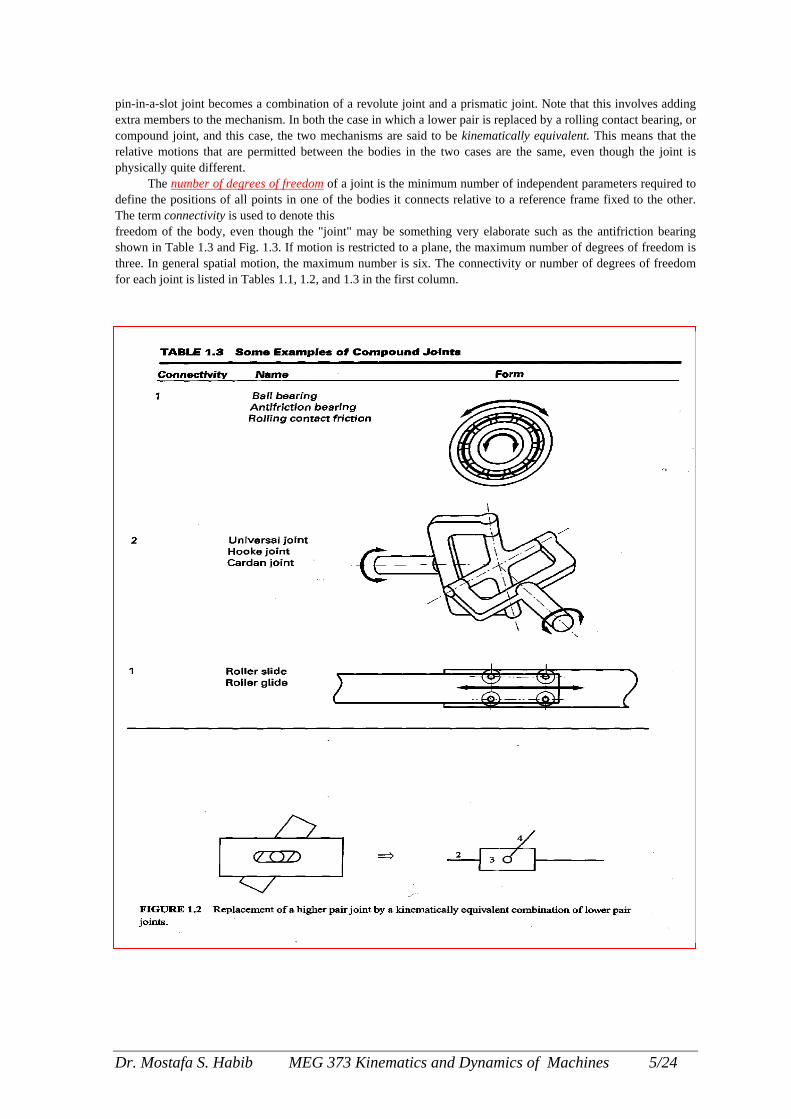
pin-in-a-slot joint becomes a combination of a revolute joint and a prismatic joint. Note that this involves adding extra members to the mechanism. In both the case in which a lower pair is replaced by a rolling contact bearing, or compound joint, and this case, the two mechanisms are said to be kinematically equivalent. This means that the relative motions that are permitted between the bodies in the two cases are the same, even though the joint is physically quite different.
The number of degrees of freedom of a joint is the minimum number of independent parameters required to define the positions of all points in one of the bodies it connects relative to a reference frame fixed to the other. The term connectivity is used to denote this freedom of the body, even though the "joint" may be something very elaborate such as the antifriction bearing shown in Table 1.3 and Fig. 1.3. If motion is restricted to a plane, the maximum number of degrees of freedom is three. In general spatial motion, the maximum number is six. The connectivity or number of degrees of freedom for each joint is listed in Tables 1.1, 1.2, and 1.3 in the first column.
Dr. Mostafa S. Habib MEG 373 Kinematics and Dynamics of Machines 5/24

FIGU
A planarallel to acompatibrevolute parallel pthe planemove onother lowfunction tuted foroperate aof motioof freedo
A
joints bmountehave thtices, anlink geospecifiegeometrthat deajoints shone witloop. A kinemclosed cclosed cPrismata slide, as thoseA framrelativeselected
Dr. Mos
RE 1.3 Various rolling-element and plain bearings.
linkage is one in which the velocities of all points in all members are directed par- plane, called the plane of motion. The only lower pair joints that are properly le with planar motion are revolute and prismatic joints. The axes of rotation of all joints must be normal to the plane of motion because points would not move in lanes otherwise. The directions of sliding of all prismatic joints must be parallel to of motion, since all points in a member connected to another by a prismatic joint lines-parallel to the sliding direction relative to the second member. Occasionally er pair joints will appear in what is otherwise a planar linkage; however, they then only as revolute or prismatic joints. For example, a spherical joint may be substi- a revolute joint, but if the linkage is functionally planar, that spherical joint will s a revolute j oint with rotation occurring only about the axis normal to the plane n. This type of situation will be discussed in more detail in the context of degrees m and mobility.
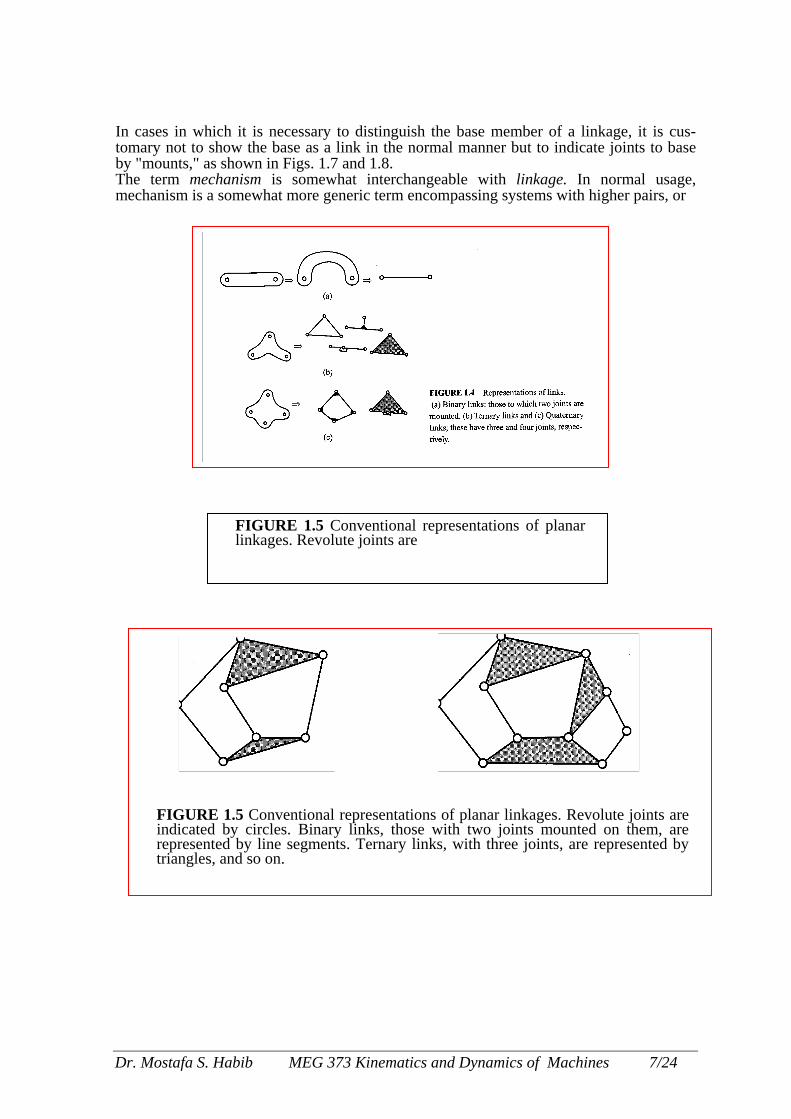
common schematic method of representing planar linkages is to represent revolute y small circles, as shown in Table 1.1. Binary links-those that have two joints d on them-are represented as lines joining those joints. Ternary links-those that ree joints mounted on them-are represented as triangles with the joints at the ver-d so on. Examples of the resulting representations are shown in Figs. 1.4-1.6. The metries may then be easily reproduced, giving an accurate view of the linkage in a d position. Alternatively, the schematic may be used conceptually without accurate ic data to indicate the topology of the linkage. Topology is the branch of geometry ls with issues of connectedness without regard to shape. Links with three or more ould be shaded or crosshatched. Otherwise, the schematic for a quaternary link,
h four joints, cannot be distinguished from the schematic for a four-bar linkage
atic chain is any assemblage of rigid links connected by kinematic joints. A hain is one in which the links and joints form one or more closed circuits. Each ircuit is a loop in which each link is attached to at least two other links. ic joints are represented by means of a line in the direction of sliding, representing with a rectangular block placed on it. This produces linkage representations such shown in Fig. 1.6. e or base member is a link that is fixed. That is, it has zero degrees of freedom to the fixed coordinate system. A linkage is a closed kinematic chain with one link as the frame.
tafa S. Habib MEG 373 Kinematics and Dynamics of Machines 6/24
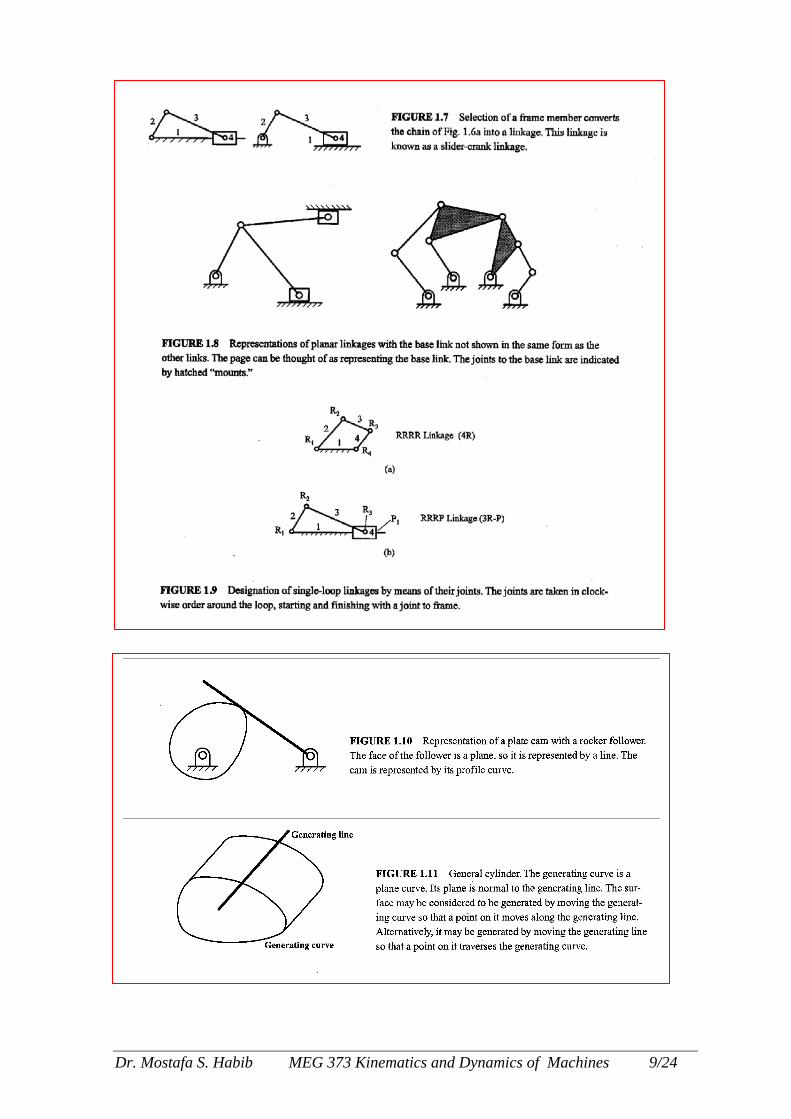
In cases in which it is necessary to distinguish the base member of a linkage, it is cus-tomary not to show the base as a link in the normal manner but to indicate joints to base by "mounts," as shown in Figs. 1.7 and 1.8. The term m chanism is somewhat interchangeable with linkage. In normal usage, mechanism i a somewhat more generic term encompassing systems with higher pairs, or
FIGUindicareprestriangl
Dr. Mostafa
es
FIGURE 1.5 Conventional representations of planar linkages. Revolute joints are
RE 1.5 Conventional representations of planar linkages. Revolute joints are ted by circles. Binary links, those with two joints mounted on them, are ented by line segments. Ternary links, with three joints, are represented by es, and so on.
S. Habib MEG 373 Kinematics and Dynamics of Machines 7/24
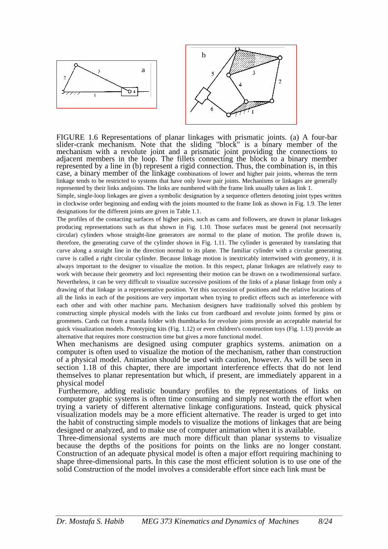
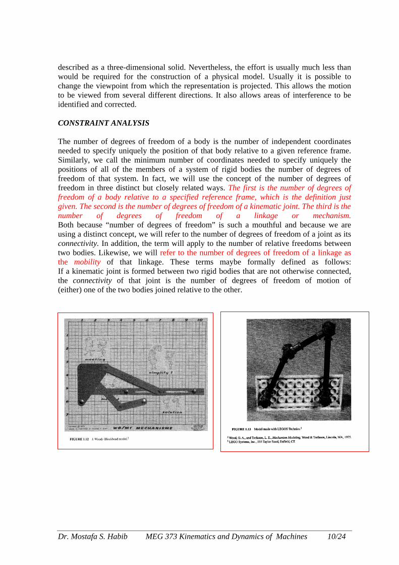
FIGURE 1.6 Representations of planar linkslider-crank mechanism. Note that the slidmechanism with a revolute joint and a priadjacent members in the loop. The fillets represented by a line in (b) represent a rigid ccase, a binary member of the linkage combinalinkage tends to be restricted to systems that have only lrepresented by their links andjoints. The links are numberSimple, single-loop linkages are given a symbolic designin clockwise order beginning and ending with the joints mdesignations for the different joints are given in Table 1.1The profiles of the contacting surfaces of higher pairs, sproducing representations such as that shown in Fig. circular) cylinders whose straight-line generators are ntherefore, the generating curve of the cylinder shown incurve along a straight line in the direction normal to itscurve is called a right circular cylinder. Because linkagealways important to the designer to visualize the motiowork with because their geometry and loci representing Nevertheless, it can be very difficult to visualize successdrawing of that linkage in a representative position. Yet all the links in each of the positions are very important each other and with other machine parts. Mechanismconstructing simple physical models with the links cutgrommets. Cards cut from a manila folder with thumbtacquick visualization models. Prototyping kits (Fig. 1.12) oalternative that requires more construction time but gives When mechanisms are designed using cocomputer is often used to visualize the motioof a physical model. Animation should be ussection 1.18 of this chapter, there are impthemselves to planar representation but whicphysical model Furthermore, adding realistic boundary pcomputer graphic systems is often time constrying a variety of different alternative linkvisualization models may be a more efficienthe habit of constructing simple models to visdesigned or analyzed, and to make use of com Three-dimensional systems are much morebecause the depths of the positions for pConstruction of an adequate physical model ishape three-dimensional parts. In this case thsolid Construction of the model involves a co
Dr. Mostafa S. Habib MEG 373 Kinema
b
a
ages with prismatic joints. (a) A four-bar ing "block" is a binary member of the smatic joint providing the connections to connecting the block to a binary member onnection. Thus, the combination is, in this
tions of lower and higher pair joints, whereas the term ower pair joints. Mechanisms or linkages are generally ed with the frame link usually taken as link 1. ation by a sequence ofletters denoting joint types written ounted to the frame link as shown in Fig. 1.9. The letter
. uch as cams and followers, are drawn in planar linkages 1.10. Those surfaces must be general (not necessarily ormal to the plane of motion. The profile drawn is,
Fig. 1.11. The cylinder is generated by translating that plane. The familiar cylinder with a circular generating motion is inextricably intertwined with geometry, it is
n. In this respect, planar linkages are relatively easy to their motion can be drawn on a twodimensional surface. ive positions of the links of a planar linkage from only a this succession of positions and the relative locations of when trying to predict effects such as interference with designers have traditionally solved this problem by
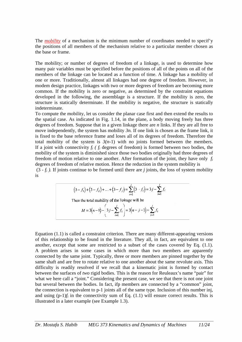
from cardboard and revolute joints formed by pins or ks for revolute joints provide an acceptable material for r even children's construction toys (Fig. 1.13) provide an a more functional model. mputer graphics systems. animation on a n of the mechanism, rather than construction ed with caution, however. As will be seen in ortant interference effects that do not lend h, if present, are immediately apparent in a
rofiles to the representations of links on uming and simply not worth the effort when age configurations. Instead, quick physical t alternative. The reader is urged to get into ualize the motions of linkages that are being puter animation when it is available. difficult than planar systems to visualize
oints on the links are no longer constant. s often a major effort requiring machining to e most efficient solution is to use one of the nsiderable effort since each link must be
tics and Dynamics of Machines 8/24
D
r. Mostafa S. Habib MEG 373 Kinematics and Dynamics of Machines 9/24
described as a three-dimensional solid. Nevertheless, the effort is usually much less than would be required for the construction of a physical model. Usually it is possible to change the viewpoint from which the representation is projected. This allows the motion to be viewed from several different directions. It also allows areas of interference to be identified and corrected. CONSTRAINT ANALYSIS The number of degrees of freedom of a body is the number of independent coordinates needed to specify uniquely the position of that body relative to a given reference frame. Similarly, we call the minimum number of coordinates needed to specify uniquely the positions of all of the members of a system of rigid bodies the number of degrees of freedom of that system. In fact, we will use the concept of the number of degrees of freedom in three distinct but closely related ways. The first is the number of degrees of freedom of a body relative to a specified reference frame, which is the definition just given. The second is the number of degrees of freedom of a kinematic joint. The third is the number of degrees of freedom of a linkage or mechanism. Both because “number of degrees of freedom” is such a mouthful and because we are using a distinct concept, we will refer to the number of degrees of freedom of a joint as its connectivity. In addition, the term will apply to the number of relative freedoms between two bodies. Likewise, we will refer to the number of degrees of freedom of a linkage as the mobility of that linkage. These terms maybe formally defined as follows: If a kinematic joint is formed between two rigid bodies that are not otherwise connected, the connectivity of that joint is the number of degrees of freedom of motion of (either) one of the two bodies joined relative to the other.
Dr. Mostafa S. Habib MEG 373 Kinematics and Dynamics of Machines 10/24
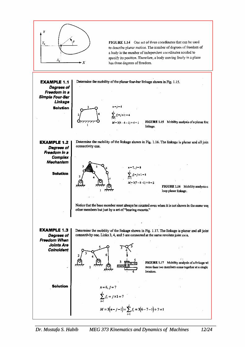
The mobility of a mechanism is the minimum number of coordinates needed to specif’y the positions of all members of the mechanism relative to a particular member chosen as the base or frame. The mobility; or number of degrees of freedom of a linkage, is used to determine how many pair variables must be specified before the positions of all of the points on all of the members of the linkage can be located as a function of time. A linkage has a mobility of one or more. Traditionally, almost all linkages had one degree of freedom. However, in modem design practice, linkages with two or more degrees of freedom are becoming more common. If the mobility is zero or negative, as determined by the constraint equations developed in the following, the assemblage is a structure. If the mobility is zero, the structure is statically determinate. If the mobility is negative, the structure is statically indeterminate. To compute the mobility, let us consider the planar case first and then extend the results to the spatial case. As indicated in Fig. 1.14, in the plane, a body moving freely has three degrees of freedom. Suppose that in a given linkage there are n links. If they are all free to move independently, the system has mobility 3n. If one link is chosen as the frame link, it is fixed to the base reference frame and loses all of its degrees of freedom. Therefore the total mobility of the system is 3(n-1) with no joints formed between the members. If a joint with connectivity fi ( fi degrees of freedom) is formed between two bodies, the mobility of the system is diminished since those two bodies originally had three degrees of freedom of motion relative to one another. After formation of the joint, they have only fi degrees of freedom of relative motion. Hence the reduction in the system mobility is (3 - fi ). If joints continue to be formed until there are j joints, the loss of system mobility is
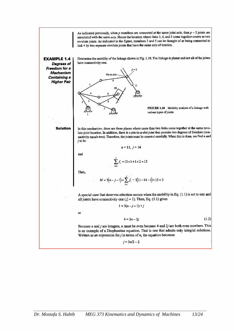
Equation (1.1) is called a constraint criterion. There are many different-appearing versions of this relationship to be found in the literature. They all, in fact, are equivalent to one another, except that some are restricted to a subset of the cases covered by Eq. (1.1). A problem arises in some cases in which more than two members are apparently connected by the same joint. Typically, three or more members are pinned together by the same shaft and are free to rotate relative to one another about the same revolute axis. This difficulty is readily resolved if we recall that a kinematic joint is formed by contact between the surfaces of two rigid bodies. This is the reason for Reuleaux’s name “pair” for what we here call a “joint.” Considering the present case, we see that there is not one joint but several between the bodies. In fact, ifp members are connected by a “common” joint, the connection is equivalent to p-1 joints all of the same type. Inclusion of this number inj, and using (p-1)fi in the connectivity sum of Eq. (1.1) will ensure correct results. This is illustrated in a later example (see Example 1.3).
Dr. Mostafa S. Habib MEG 373 Kinematics and Dynamics of Machines 11/24
Dr. Mostafa S. Habib MEG 373 Kinematics and Dynamics of Machines 12/24 Dr. Mostafa S. Habib MEG 373 Kinematics and Dynamics of Machines 12/24
Dr.
Mostafa S. Habib MEG 373 Kinematics and Dynamics of Machines 13/24
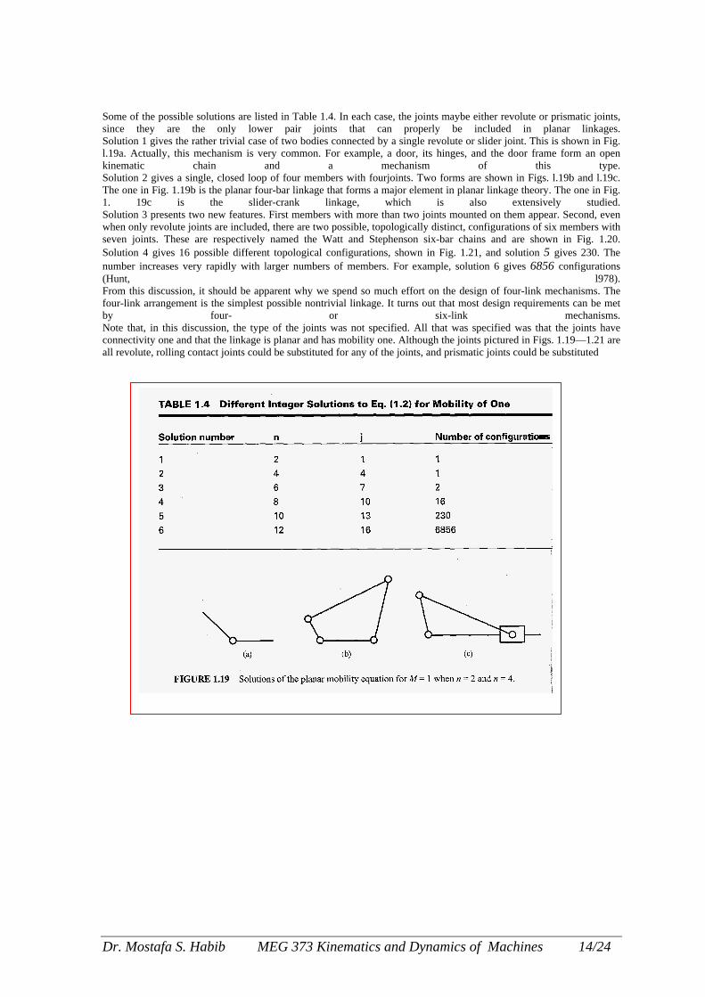
Some of the possible solutions are listed in Table 1.4. In each case, the joints maybe either revolute or prismatic joints, since they are the only lower pair joints that can properly be included in planar linkages. Solution 1 gives the rather trivial case of two bodies connected by a single revolute or slider joint. This is shown in Fig. l.19a. Actually, this mechanism is very common. For example, a door, its hinges, and the door frame form an open kinematic chain and a mechanism of this type. Solution 2 gives a single, closed loop of four members with fourjoints. Two forms are shown in Figs. l.19b and l.19c. The one in Fig. 1.19b is the planar four-bar linkage that forms a major element in planar linkage theory. The one in Fig. 1. 19c is the slider-crank linkage, which is also extensively studied. Solution 3 presents two new features. First members with more than two joints mounted on them appear. Second, even when only revolute joints are included, there are two possible, topologically distinct, configurations of six members with seven joints. These are respectively named the Watt and Stephenson six-bar chains and are shown in Fig. 1.20. Solution 4 gives 16 possible different topological configurations, shown in Fig. 1.21, and solution 5 gives 230. The number increases very rapidly with larger numbers of members. For example, solution 6 gives 6856 configurations (Hunt, l978). From this discussion, it should be apparent why we spend so much effort on the design of four-link mechanisms. The four-link arrangement is the simplest possible nontrivial linkage. It turns out that most design requirements can be met by four- or six-link mechanisms. Note that, in this discussion, the type of the joints was not specified. All that was specified was that the joints have connectivity one and that the linkage is planar and has mobility one. Although the joints pictured in Figs. 1.19—1.21 are all revolute, rolling contact joints could be substituted for any of the joints, and prismatic joints could be substituted
Dr. Mostafa S. Habib MEG 373 Kinematics and Dynamics of Machines 14/24
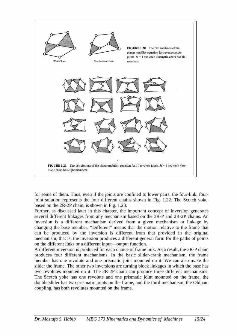
for some of them. Thus, even if the joints are confined to lower pairs, the four-link, four- joint solution represents the four different chains shown in Fig. 1.22. The Scotch yoke, based on the 2R-2P chain, is shown in Fig. 1.23. Further, as discussed later in this chapter, the important concept of inversion generates several different linkages from any mechanism based on the 3R-P and 2R-2P chains. An inversion is a different mechanism derived from a given mechanism or linkage by changing the base member. “Different” means that the motion relative to the frame that can be produced by the inversion is different from that provided in the original mechanism, that is, the inversion produces a different general form for the paths of points on the different links or a different input—output function. A different inversion is produced for each choice of frame link. As a result, the 3R-P chain produces four different mechanisms. In the basic slider-crank mechanism, the frame member has one revolute and one prismatic joint mounted on it. We can also make the slider the frame. The other two inversions are turning block linkages in which the base has two revolutes mounted on it. The 2R-2P chain can produce three different mechanisms: The Scotch yoke has one revolute and one prismatic joint mounted on the frame, the double slider has two prismatic joints on the frame, and the third mechanism, the Oldham coupling, has both revolutes mounted on the frame.
Dr. Mostafa S. Habib MEG 373 Kinematics and Dynamics of Machines 15/24

1AoooTiaasNcrTwi
D
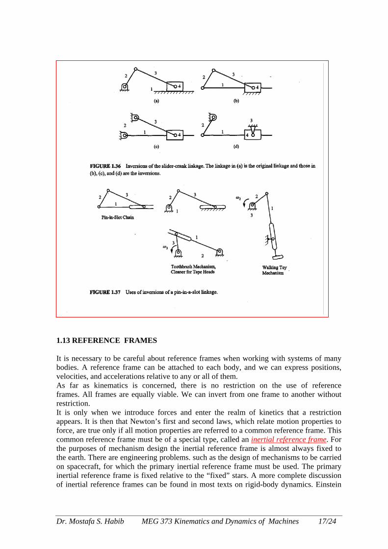
.12 INVERSION commonly used tactic in studying mechanism kinematics is inversion. This is a change f the fixed reference frame from one link to another that causes different characteristics f the motion relative to the frame. For example, Fig. 1.36 shows the different inversions f a slider-crank linkage, and Fig. 1.37 shows the inversions of a pin-in-a-slot mechanism. he pin-in-a-slot inversions are often used as inexpensive substitutes for the slider-crank
nversions. The motion characteristics of the coupler links for each of the mechanisms are ll very different. Nevertheless, the linkage topology and the relative angular relationships mong the links are the same in all cases. Therefore, useful information obtained from the tudy of the linkage in one inversion can be transferred to the study of other inversions. ote that in Fig. 1.36, the relative positions of all of the joints are the same for the position
hosen. It is only when the mechanisms move that the different motion characteristics are evealed. o determine the inversions of a mechanism, it is convenient to start with the chain from hich the mechanism is formed. A different linkage results whenever a different link
s selected as the frame.
r. Mostafa S. Habib MEG 373 Kinematics and Dynamics of Machines 16/24
1 IbvAfrIafcttoio
D
.13 REFERENCE FRAMES t is necessary to be careful about reference frames when working with systems of many odies. A reference frame can be attached to each body, and we can express positions, elocities, and accelerations relative to any or all of them. s far as kinematics is concerned, there is no restriction on the use of reference
rames. All frames are equally viable. We can invert from one frame to another without estriction. t is only when we introduce forces and enter the realm of kinetics that a restriction ppears. It is then that Newton’s first and second laws, which relate motion properties to orce, are true only if all motion properties are referred to a common reference frame. This ommon reference frame must be of a special type, called an inertial reference frame. For he purposes of mechanism design the inertial reference frame is almost always fixed to he earth. There are engineering problems. such as the design of mechanisms to be carried n spacecraft, for which the primary inertial reference frame must be used. The primary nertial reference frame is fixed relative to the “fixed” stars. A more complete discussion f inertial reference frames can be found in most texts on rigid-body dynamics. Einstein
r. Mostafa S. Habib MEG 373 Kinematics and Dynamics of Machines 17/24

showed that in a space—time framework all reference frames are equally valid, thereby removing the Newtonian distinction between inertial reference frames and others. However, in the domain in which mechanical engineers usually operate, Newtonian mechanics provides a very accurate simplification of relativistic mechanics that is of great practical utility. It is important to remember that position and motion properties can be expressed only relative to a reference frame. The habit of referring to a velocity or acceleration of a point relative to another point has been commonplace in this subject. This will be found to be convenient in some types of problems, particularly in graphical analysis, and there is no harm in using it provided that it is clearly understood that it is a shorthand expression for the velocity or acceleration of the first point relative to a reference frame in which the second point is fixed. The identity of that reference frame should always be kept in mind. In many discussions in the following, it will be convenient to have a notation that explicitly states the reference frame in which a particular vector is expressed. A method that is often used is to indicate the reference frame by means of a superscript placed in front of the symbol for the vectot For example, 1VA indicates the velocity of point A relative to reference frame 1, and 2w3 indicates the angular velocity of member 3 relative to reference frame 2. Usually, we will associate one reference frame with each member of a linkage and will number it to agree with the number of the linkage. Reference frame 1 will usually refer to the fixed link. Unfortunately, the use of superscripts to indicate reference frames complicates expressions and makes them more difficult to read. For this reason, the superscripts will usually be dropped when all vectors are referred to reference frame 1. 1.14 MOTION LIMITS (Extreme Positions) A member of a linkage that is connected to the base by a revolute joint and that rotates completely as the linkage moves through its motion cycle is called a crank. Usually, there will also be members in the linkage that look exactly like cranks because they are connected to the base by a revolute, but these cannot rotate completely.
FIGURE 1.38 Limiting positions of joint C of a four bar linkages
Dr. Mostafa S. Habib MEG 373 Kinematics and Dynamics of Machines 18/24
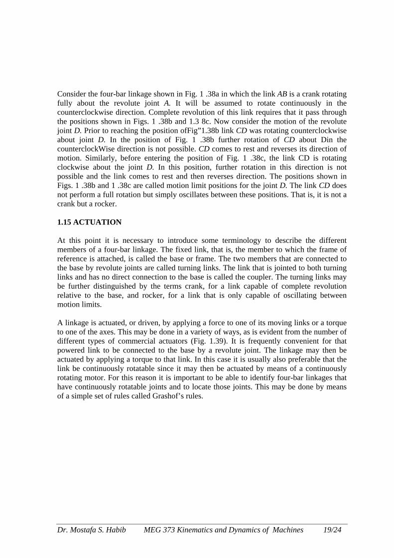
Consider the four-bar linkage shown in Fig. 1 .38a in which the link AB is a crank rotating fully about the revolute joint A. It will be assumed to rotate continuously in the counterclockwise direction. Complete revolution of this link requires that it pass through the positions shown in Figs. 1 .38b and 1.3 8c. Now consider the motion of the revolute joint D. Prior to reaching the position ofFig”1.38b link CD was rotating counterclockwise about joint D. In the position of Fig. 1 .38b further rotation of CD about Din the counterclockWise direction is not possible. CD comes to rest and reverses its direction of motion. Similarly, before entering the position of Fig. 1 .38c, the link CD is rotating clockwise about the joint D. In this position, further rotation in this direction is not possible and the link comes to rest and then reverses direction. The positions shown in Figs. 1 .38b and 1 .38c are called motion limit positions for the joint D. The link CD does not perform a full rotation but simply oscillates between these positions. That is, it is not a crank but a rocker. 1.15 ACTUATION At this point it is necessary to introduce some terminology to describe the different members of a four-bar linkage. The fixed link, that is, the member to which the frame of reference is attached, is called the base or frame. The two members that are connected to the base by revolute joints are called turning links. The link that is jointed to both turning links and has no direct connection to the base is called the coupler. The turning links may be further distinguished by the terms crank, for a link capable of complete revolution relative to the base, and rocker, for a link that is only capable of oscillating between motion limits. A linkage is actuated, or driven, by applying a force to one of its moving links or a torque to one of the axes. This may be done in a variety of ways, as is evident from the number of different types of commercial actuators (Fig. 1.39). It is frequently convenient for that powered link to be connected to the base by a revolute joint. The linkage may then be actuated by applying a torque to that link. In this case it is usually also preferable that the link be continuously rotatable since it may then be actuated by means of a continuously rotating motor. For this reason it is important to be able to identify four-bar linkages that have continuously rotatable joints and to locate those joints. This may be done by means of a simple set of rules called Grashof’s rules.
Dr. Mostafa S. Habib MEG 373 Kinematics and Dynamics of Machines 19/24
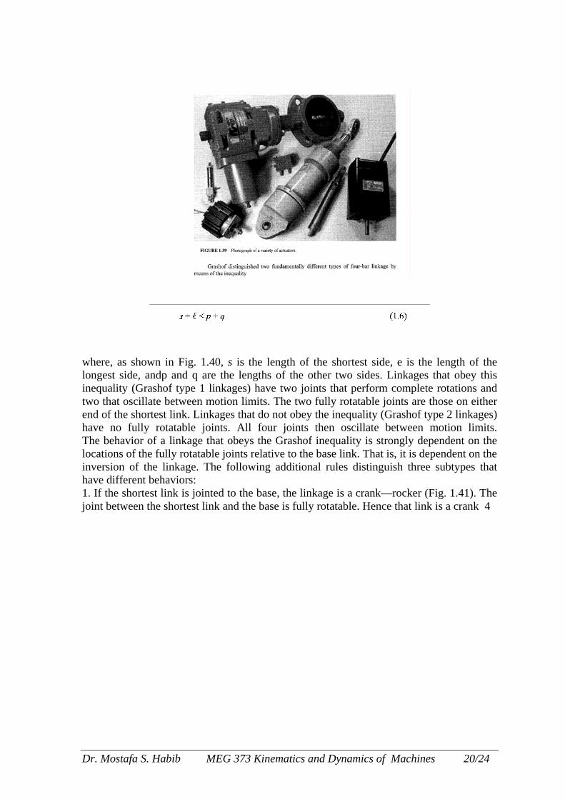
where, as shown in Fig. 1.40, s is the length of the shortest side, e is the length of the longest side, andp and q are the lengths of the other two sides. Linkages that obey this inequality (Grashof type 1 linkages) have two joints that perform complete rotations and two that oscillate between motion limits. The two fully rotatable joints are those on either end of the shortest link. Linkages that do not obey the inequality (Grashof type 2 linkages) have no fully rotatable joints. All four joints then oscillate between motion limits. The behavior of a linkage that obeys the Grashof inequality is strongly dependent on the locations of the fully rotatable joints relative to the base link. That is, it is dependent on the inversion of the linkage. The following additional rules distinguish three subtypes that have different behaviors: 1. If the shortest link is jointed to the base, the linkage is a crank—rocker (Fig. 1.41). The joint between the shortest link and the base is fully rotatable. Hence that link is a crank 4
Dr. Mostafa S. Habib MEG 373 Kinematics and Dynamics of Machines 20/24
Dr. Mostafa S. Habib MEG 373 Kinematics and Dynamics of Machines 21/24

Dr. Mostafa S. Habib MEG 373 Kinematics and Dynamics of Machines 22/24

Dr. Mostafa S. Habib MEG 373 Kinematics and Dynamics of Machines 23/24
Dr. Mostafa S. Habib MEG 373 Kinematics and Dynamics of Machines 24/24