DEPARTMENT OF MECHANICAL ENGINEERING ME …studentsfocus.com/notes/anna_university/Mech/7SEM/ME6005...
22
DEPARTMENT OF MECHANICAL ENGINEERING SEMESTER – VII ME 6005 PROCESS PLANNING AND COST ESTIMATION QUESTION BANK UNIT – I INTRODUCTION TO PROCESS PLANNING PART – A (2 Marks) 1 Define process planning. BT1 2 Select the process parameter for setting machines and tooling's. BT3 3 Identify the process planning activities. BT1 4 Summarize the factors influencing process selection. BT2 5 Summarize the use of drawings interpretation in processing requirement. BT2 6 Quote the data is listed for each component of the product in the process sheet. BT1 7 List the use of process Sheet. BT1 8 Prioritize the sort of information can the process planner obtained from the engineering drawing of the component. BT5 9 Give a procedure for process planning for the manufacture of a component in machine shop. BT2 10 List the objectives of process planning. BT1 11 Discuss the various parameters considered in the material selection? BT2 12 Illustrate the factors considered for selection of machines and tooling's. BT3 13 Show the steps involved in process design. BT1 14 Classify the work holding Devices and why they are used. BT3 15 Point out the main inputs and outputs for process planning activity. BT4 16 Originate the advantages and disadvantages of process planning BT6 17 Assume a process flow chart and how would it be used to help formulate a process plan. BT4 18 Justify the importance of process planner to have a good knowledge of materials used in manufacturing? BT5 19 Categorize the main approaches of process planning. BT4 20 Compose the documents required for Process Planning? BT6 PART – B 1 (a) Identify the steps involved in Process Design. (8) BT1 (b) Examine the basic factors affecting Process Design. (8) BT1 2 (a) Describe the steps or procedures involved in Process Planning. (10) BT1 (b) Show the data is listed for each component of the product in the process sheet.(6) BT1 3 Explain with neat sketch and the steps followed for material selection process and methods. (16) BT4 4 Show the two approaches to Process Planning in the context of CAPP (Computer BT1 www.studentsfocus.com
-
Upload
trinhkhanh -
Category
Documents
-
view
218 -
download
4
Transcript of DEPARTMENT OF MECHANICAL ENGINEERING ME …studentsfocus.com/notes/anna_university/Mech/7SEM/ME6005...
DEPARTMENT OF MECHANICAL ENGINEERING
SEMESTER – VII
ME 6005 PROCESS PLANNING AND COST ESTIMATION
QUESTION BANK
UNIT – I
INTRODUCTION TO PROCESS PLANNING
PART – A (2 Marks)
1 Define process planning. BT1 2 Select the process parameter for setting machines and tooling's. BT3 3 Identify the process planning activities. BT1 4 Summarize the factors influencing process selection. BT2 5 Summarize the use of drawings interpretation in processing requirement. BT2 6 Quote the data is listed for each component of the product in the process sheet. BT1 7 List the use of process Sheet. BT1 8 Prioritize the sort of information can the process planner obtained from the
engineering drawing of the component. BT5
9 Give a procedure for process planning for the manufacture of a component in machine shop. BT2
10 List the objectives of process planning. BT1 11 Discuss the various parameters considered in the material selection? BT2 12 Illustrate the factors considered for selection of machines and tooling's. BT3 13 Show the steps involved in process design. BT1 14 Classify the work holding Devices and why they are used. BT3 15 Point out the main inputs and outputs for process planning activity. BT4 16 Originate the advantages and disadvantages of process planning BT6 17 Assume a process flow chart and how would it be used to help formulate a process
plan. BT4
18 Justify the importance of process planner to have a good knowledge of materials used in manufacturing? BT5
19 Categorize the main approaches of process planning. BT4 20 Compose the documents required for Process Planning? BT6
PART – B 1 (a) Identify the steps involved in Process Design. (8) BT1 (b) Examine the basic factors affecting Process Design. (8) BT1
2 (a) Describe the steps or procedures involved in Process Planning. (10) BT1 (b) Show the data is listed for each component of the product in the process sheet.(6) BT1
3 Explain with neat sketch and the steps followed for material selection process and methods. (16)
BT4
4 Show the two approaches to Process Planning in the context of CAPP (Computer BT1
www.studentsfocus.com
Aided Process Planning)? Explain them clearly. (16) 5 Explain briefly the factors considered for selection of Equipments for process
planning? (16) BT4
6 (a) Discuss the various parameters considered in the material selection? (8) BT2 (b) Summarize the documents required for Process Planning? (8) BT2
7 (a) Classify the four distinct processing strategies (8) BT2 (b) Summarize the process layout with neat sketch. (8) BT2
8 Describe the various factors which govern the selection of a manufacturing process. (16)
BT1
9 Identify and describe at least five types of geometrical tolerances? (16) BT3 10 Generalize the factors that affect tooling performance. (16) BT6 11 Summarize the factors are taken into consideration in Process Selection and Machine
Selection? (16) BT2
12 Explain briefly the constraints that must be considered in tool selection (16) BT5 13 Analyze briefly about the tooling for machinability. (16) BT4 14 Illustrate the three analyses that can be carried out during drawing interpretation.(16) BT3
www.studentsfocus.com

UNIT – II
PROCESS PLANNING ACTIVITIES
PART – A (2 Marks)
1 Give the factors that considered in Depth of Cut. BT2 2 List the factors Considered for selecting Process parameter. BT1 3 A planer is capable of 15 strokes per minute over a stroke length of 2m. The cutting
time ratio for the machine is 4:3. Determine cutting speed. BT1
4 Infer the factors previously considered for the tooling decision are the most influential on the calculation of the process parameters. BT3
5 What are the general recommendations for cutting depths for turning and boring? BT2 6 Define cutting speed. BT1 7 Classify how milling operations can be classified. BT2 8 Classify the three basic functions of Jig. BT3 9 Show the general factors that will influence the design and/or construction of a work
holder. BT3
10 Analyze the basic principles of jig and fixture design can be categorized BT4 11 Show the main reasons for the use of jigs and fixtures. BT1 12 Draw the flow chart for design methodology for work holders BT6 13 Categorize the main factors to be considered for work holding device. BT4 14 Point out the quality function for process plan BT4 15 Discuss how does the process planner use cost data? BT6 16 Assess the three elements of Direct cost BT5 17 Summarize major influences on the cost of materials for manufacture(BT-5) BT5 18 Quote the purpose of work holding Devices BT1 19 Calculate the spindle speed required to turn a 75mm diameter shoulder on a low-
carbon steel component using a high-speed steel tool. What is the percentage increase in cutting speed if a carbide tool is used instead?
BT1
20 Illustrate the formula to calculate the machining times for turning and boring. BT2 PART – B
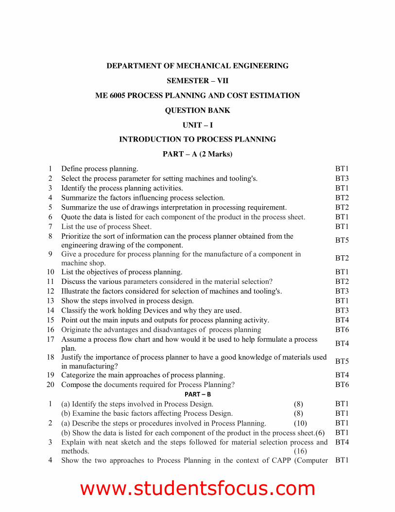
1 The top surface of the aluminum alloy component shown in Fig is to be milled by slab milling. It will be machined by a Ø20mm HSS cutter with eight cutting teeth at a constant surface speed of 45m min-1.The depth of cut is 4 mm and the milling machine is capable of spindle speeds of up to 3000 rpm. Determine: (16) (i) if the mill is capable of machining the component at the required surface speed (ii) the total machining time for the component if the mill is capable.
BT1
www.studentsfocus.com
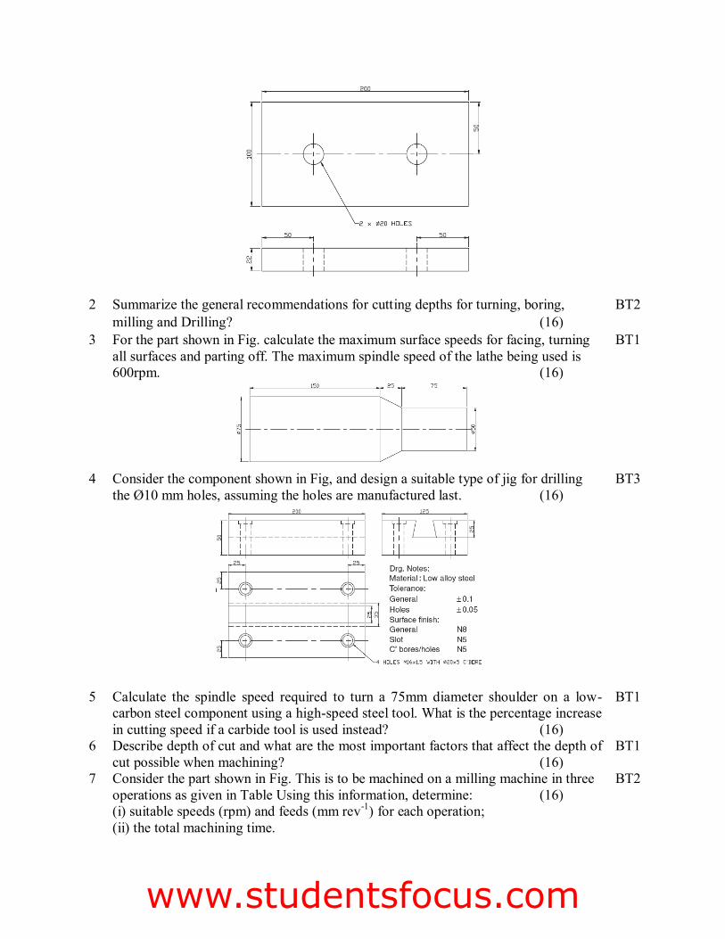
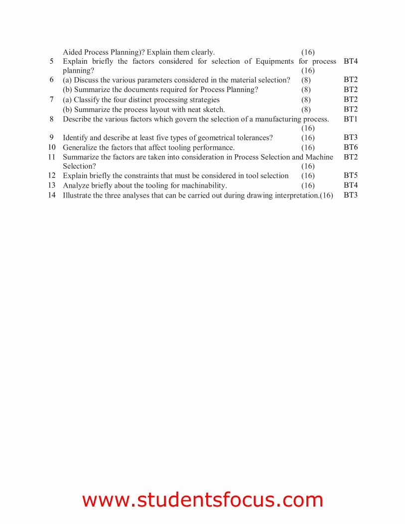
2 Summarize the general recommendations for cutting depths for turning, boring, milling and Drilling? (16)
BT2
3 For the part shown in Fig. calculate the maximum surface speeds for facing, turning all surfaces and parting off. The maximum spindle speed of the lathe being used is 600rpm. (16)
BT1
4 Consider the component shown in Fig, and design a suitable type of jig for drilling the Ø10 mm holes, assuming the holes are manufactured last. (16)
BT3
5 Calculate the spindle speed required to turn a 75mm diameter shoulder on a low-carbon steel component using a high-speed steel tool. What is the percentage increase in cutting speed if a carbide tool is used instead? (16)
BT1
6 Describe depth of cut and what are the most important factors that affect the depth of cut possible when machining? (16)
BT1
7 Consider the part shown in Fig. This is to be machined on a milling machine in three operations as given in Table Using this information, determine: (16) (i) suitable speeds (rpm) and feeds (mm rev-1) for each operation; (ii) the total machining time.
BT2
www.studentsfocus.com

8 (a) Show the seven quality control tools and techniques relate to quality improvement and problem solving? (10)
BT3
(b) Compare the difference between process control and process capability? (6) BT3 9 Explain the typical quality characteristics are measured in quality control? (8) BT4 Compare the difference when ‘measuring’ variables and attributes? (8) BT4
10 A large computer manufacturer requires 1200 printed circuit board (PCB) carriers every month for the production of the PCBs themselves. Within their tool room, they have a variety of machining processes available and the carriers are produced on a conventional milling machine. The following information relates to the PCB carrier manufacture: (16) Set-up time 1 h 20 min Machining time 39 min Material cost/unit Rs.5.62 Machinist’s hourly rate Rs.9.85/h
BT3
11 Formulate a case study for the standard parts of Jigs and fixtures. (16) BT6 12 (a) Point out the documents required for Process Planning? (8) BT4 (b) Analyze the different factors considered in developing a manufacturing logic? (8) BT4
12 Explain the main categories of cost and how are they related? (8) BT4 13 Explain prime cost and how does it relate to the cost categories. (8) BT4 14 (a) Summarize the main factors must be considered according to the principles of jig
and fixture design? (10) BT2
(b) Discuss the main steps in designing a jig/fixture? (6) BT2
www.studentsfocus.com
UNIT – III
INTRODUCTION TO COST ESTIMATION
PART - A ( 2 Marks)
1 Define cost accounting. BT1 2 Distinguish between cost estimation and cost accounting. BT2 3 List the types of estimates BT1 4 Classify the sources of cost estimation? BT4 5 Point out any two objectives of cost estimation BT4 6 Summarize batch costing BT5 7 Describe briefly standard data BT2 8 Define under estimate BT1 9 Explain about target cost BT5 10 Explain briefly about conceptual cost estimating BT4 11 Define contingency allowances BT1 12 Illustrate briefly the characteristics of realistic estimates? BT3 13 Classify the allowances considered in cost estimation BT3 14 Give the methods of costing BT2 15 Demonstrate how the standard data is developed? BT3 16 Explain briefly about depreciation? BT4 17 Define multiple cost method BT1 18 Generalize the meaning direct material with an example BT6 19 Give any two functions of cost estimation BT2 20 Define parametric estimating BT1
PART – B 1 (a) Discuss the objectives of cost estimation (10) BT2 (b) Give the advantages of cost accounting (6) BT2 2 With suitable application examples classify costs (16) BT3 3 (a) Discuss various types of estimates (10) BT2 (b) Explain the data requirements for cost estimation and their sources (6) BT4 4 (a) Describe the different methods of estimates (10) BT1 (b) Explain the allowances in estimation (6) BT4 5 Describe step by step procedure for estimating the direct material cost (16) BT1 6 Explain the various allowances to be considered in estimation of direct labour cost
(16) BT4
7 (a) Differentiate cost accounting and cost estimating (8) BT2 (b) Give the basic steps in cost estimation (8) BT2 8 Calculate prime cost, factory cost, production cost, total cost and selling price per
item from the data given below for the year 2012-13 (16) Cost of raw material in stock as on 1.4.2012 - Rs 25,000 Raw material purchased - Rs 40,000 Direct labour cost - Rs 14,000 Direct expense - Rs 1,000
BT3
www.studentsfocus.com
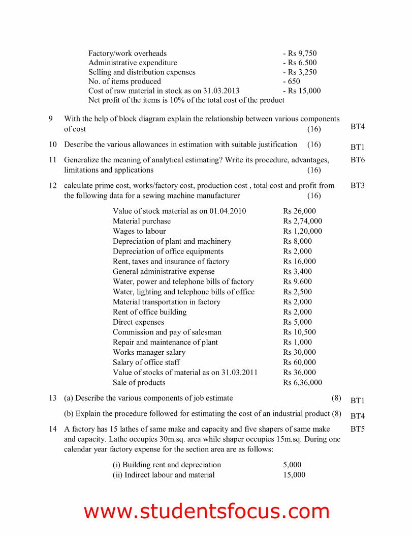
Factory/work overheads - Rs 9,750 Administrative expenditure - Rs 6.500 Selling and distribution expenses - Rs 3,250 No. of items produced - 650 Cost of raw material in stock as on 31.03.2013 - Rs 15,000 Net profit of the items is 10% of the total cost of the product
9 With the help of block diagram explain the relationship between various components of cost (16) BT4
10 Describe the various allowances in estimation with suitable justification (16) BT1 11 Generalize the meaning of analytical estimating? Write its procedure, advantages,
limitations and applications (16) BT6
12 calculate prime cost, works/factory cost, production cost , total cost and profit from the following data for a sewing machine manufacturer (16)
Value of stock material as on 01.04.2010 Rs 26,000 Material purchase Rs 2,74,000 Wages to labour Rs 1,20,000 Depreciation of plant and machinery Rs 8,000 Depreciation of office equipments Rs 2,000 Rent, taxes and insurance of factory Rs 16,000 General administrative expense Rs 3,400 Water, power and telephone bills of factory Rs 9.600 Water, lighting and telephone bills of office Rs 2,500 Material transportation in factory Rs 2,000 Rent of office building Rs 2,000 Direct expenses Rs 5,000 Commission and pay of salesman Rs 10,500 Repair and maintenance of plant Rs 1,000 Works manager salary Rs 30,000 Salary of office staff Rs 60,000 Value of stocks of material as on 31.03.2011 Rs 36,000 Sale of products Rs 6,36,000
BT3
13 (a) Describe the various components of job estimate (8) BT1 (b) Explain the procedure followed for estimating the cost of an industrial product (8) BT4 14 A factory has 15 lathes of same make and capacity and five shapers of same make
and capacity. Lathe occupies 30m.sq. area while shaper occupies 15m.sq. During one calendar year factory expense for the section area are as follows:
(i) Building rent and depreciation 5,000 (ii) Indirect labour and material 15,000
BT5
www.studentsfocus.com

(iii) Insurance 2,000 (iv) Depreciation charges of lathe 5,000 (v) Depreciation charges of shapers 3,000 (vi) Power consumption for lathe 2,000 (vii) Power consumption for shapers 1,000
Evaluate the machine hour rate for lathes and shapers work for 25,000 hrs and 8,000 hrs respectively (16)
www.studentsfocus.com
UNIT – IV
PRODUCTION COST ESTIMATION
PART – A (2 Marks)
1 How do you estimate the time required for forging? BT2 2 Explain the actual welding costs involved in estimation in welding shop? BT5 3 List the losses to be considered in estimating the gross weight of a forging component BT1 4 Recommend the costs to be considered for estimating electric welding cost of a product? BT5 5 Illustrate how to estimate the gas cutting costs BT3 6 Give the losses in forging process. BT2 7 List the various sections that will be normally found in a foundry shop. BT1 8 List the various elements of cost involved in the total cost of manufacturing a casting. BT1 9 Explain overhead expenses. BT4 10 Explain how cost estimation is done in respect of a welded component or welding job. BT4 11 List the various elements of cost involved in weldment or a welded component. BT1 12 What are the various costs involved in the calculation of total cost of forged components. BT3 13 What is pattern making and fettling in foundry? Generalize it BT6 14 Differentiate leftward and rightward welding? BT2 15 List the types of forging processes BT1 16 Explain machine forging or upset forging in a brief manner. BT4 17 Define press forging BT1 18 Generalize the meaning of tonghold loss in forging? BT6 19 Describe briefly a sprue loss? BT2 20 Give the formula for calculating the cost of power consumed in arc welding. BT2
PART – B 1
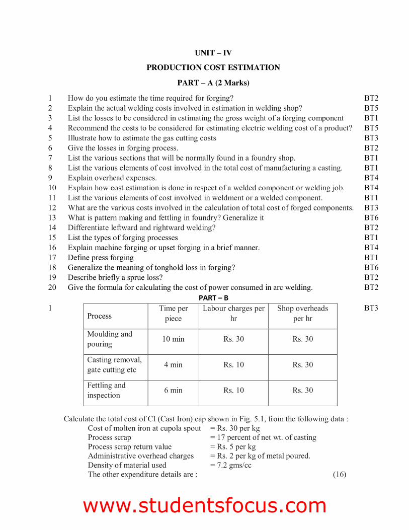
Calculate the total cost of CI (Cast Iron) cap shown in Fig. 5.1, from the following data : Cost of molten iron at cupola spout = Rs. 30 per kg Process scrap = 17 percent of net wt. of casting Process scrap return value = Rs. 5 per kg Administrative overhead charges = Rs. 2 per kg of metal poured. Density of material used = 7.2 gms/cc The other expenditure details are : (16)
Process Time per
piece Labour charges per
hr Shop overheads
per hr
Moulding and pouring 10 min Rs. 30 Rs. 30
Casting removal, gate cutting etc 4 min Rs. 10 Rs. 30
Fettling and inspection 6 min Rs. 10 Rs. 30
BT3
www.studentsfocus.com
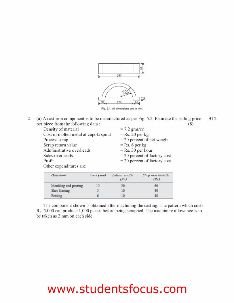
2 (a) A cast iron component is to be manufactured as per Fig. 5.2. Estimate the selling price per piece from the following data : (8)
Density of material = 7.2 gms/cc Cost of molten metal at cupola spout = Rs. 20 per kg Process scrap = 20 percent of net weight Scrap return value = Rs. 6 per kg Administrative overheads = Rs. 30 per hour Sales overheads = 20 percent of factory cost Profit = 20 percent of factory cost Other expenditures are:
The component shown is obtained after machining the casting. The pattern which costs Rs. 5,000 can produce 1,000 pieces before being scrapped. The machining allowance is to be taken as 2 mm on each side
BT2
www.studentsfocus.com
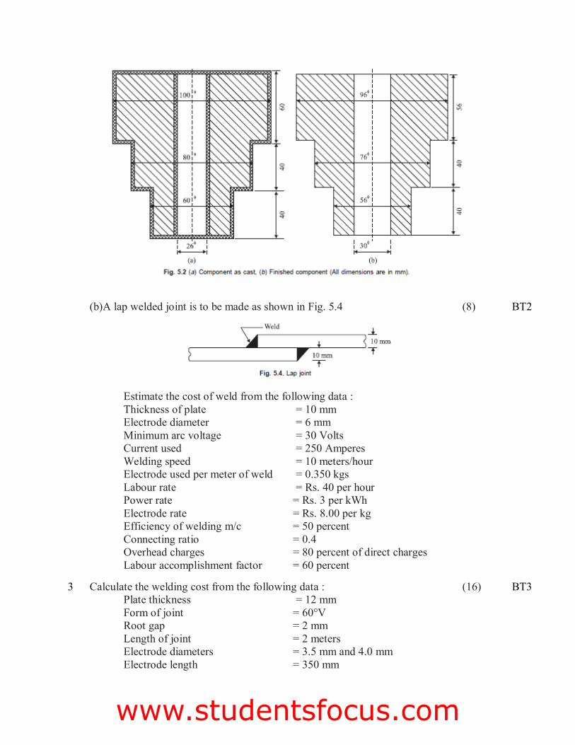
(b)A lap welded joint is to be made as shown in Fig. 5.4 (8)
Estimate the cost of weld from the following data : Thickness of plate = 10 mm Electrode diameter = 6 mm Minimum arc voltage = 30 Volts Current used = 250 Amperes Welding speed = 10 meters/hour Electrode used per meter of weld = 0.350 kgs Labour rate = Rs. 40 per hour Power rate = Rs. 3 per kWh Electrode rate = Rs. 8.00 per kg Efficiency of welding m/c = 50 percent Connecting ratio = 0.4 Overhead charges = 80 percent of direct charges Labour accomplishment factor = 60 percent
BT2
3 Calculate the welding cost from the following data : (16) Plate thickness = 12 mm Form of joint = 60°V Root gap = 2 mm Length of joint = 2 meters Electrode diameters = 3.5 mm and 4.0 mm Electrode length = 350 mm
BT3
www.studentsfocus.com
Electrodes required per meter weld = 10 nos. of 3.5 mm dia and for 100 per cent efficiency and 24 nos. of 4 mm dia 50 mm stub length
Average deposition h = 80 percent Melting time per electrode = 1.3 minutes for 3.5 mm dia
and1.50minutes for 4 mm dia electrode Connecting ratio = 2 Hourly welding rate = Rs. 40 Overhead charges = 40 percent of welding cost
4 Evaluate the welding cost for a cylindrical boiler drum 2.5 m × 1 m diameter which is to be made from 15 mm thick m.s plates. Both the ends are closed by arc welding of circular plates to the drum. Cylindrical portion is welded along the longitudinal seam and welding is done both in inner and outer sides. Assume the following data: (16)
(i) Rate of welding = 2 meters per hour on inner side and 2.5 meters per hour on outer side
(ii) Length of electrodes required = 1.5 m/ meter of weld length (iii) Cost of electrode = Rs. 0.60 per meter (iv) Power consumption = 4 kWh/meter of weld (v) Power charges = Rs. 3/kWh (vi) Labour charges = Rs. 40/hour (vii) Other overheads = 200 percent of prime cost (viii) Discarded electrodes = 5 percent (ix) Fatigue and setting up time = 6 percent of welding time
BT6
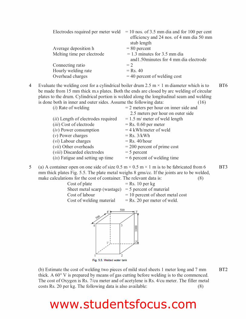
5 (a) A container open on one side of size 0.5 m × 0.5 m × 1 m is to be fabricated from 6 mm thick plates Fig. 5.5. The plate metal weighs 8 gms/cc. If the joints are to be welded, make calculations for the cost of container. The relevant data is: (8)
Cost of plate = Rs. 10 per kg Sheet metal scarp (wastage) = 5 percent of material Cost of labour = 10 percent of sheet metal cost Cost of welding material = Rs. 20 per meter of weld.
BT3
(b) Estimate the cost of welding two pieces of mild steel sheets 1 meter long and 7 mm thick. A 60° V is prepared by means of gas cutting before welding is to the commenced. The cost of Oxygen is Rs. 7/cu meter and of acetylene is Rs. 4/cu meter. The filler metal costs Rs. 20 per kg. The following data is also available: (8)
BT2
www.studentsfocus.com
For gas cutting (For 10 mm thick plate) Cutting speed = 20 m/hr Consumption of Oxygen = 2 cu meter/hr Consumption of acetylene = 0.2 cu meter/hr
Data for Rightward Welding (For 7 mm thick plate) Consumption of Oxygen = 0.8 cu meter/hr Consumption of acetylene = 0.8 cu meter/hr Dia of filler rod used = 3.5 mm Filler rod used per meter of weld = 3.4 meters Rate of welding = 3 meters/hr Density of filler metal = 8 gm/cc
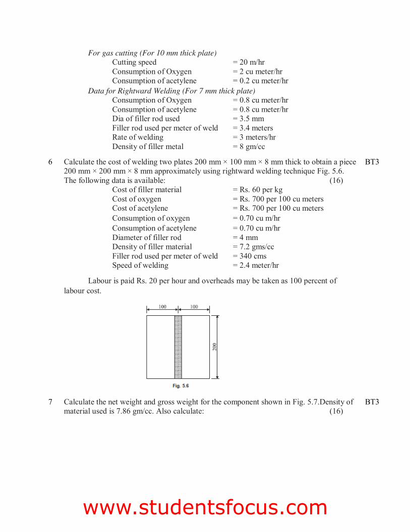
6 Calculate the cost of welding two plates 200 mm × 100 mm × 8 mm thick to obtain a piece 200 mm × 200 mm × 8 mm approximately using rightward welding technique Fig. 5.6. The following data is available: (16) Cost of filler material = Rs. 60 per kg
Cost of oxygen = Rs. 700 per 100 cu meters Cost of acetylene = Rs. 700 per 100 cu meters Consumption of oxygen = 0.70 cu m/hr Consumption of acetylene = 0.70 cu m/hr Diameter of filler rod = 4 mm Density of filler material = 7.2 gms/cc Filler rod used per meter of weld = 340 cms Speed of welding = 2.4 meter/hr
Labour is paid Rs. 20 per hour and overheads may be taken as 100 percent of labour cost.
BT3
7 Calculate the net weight and gross weight for the component shown in Fig. 5.7.Density of material used is 7.86 gm/cc. Also calculate: (16)
BT3
www.studentsfocus.com
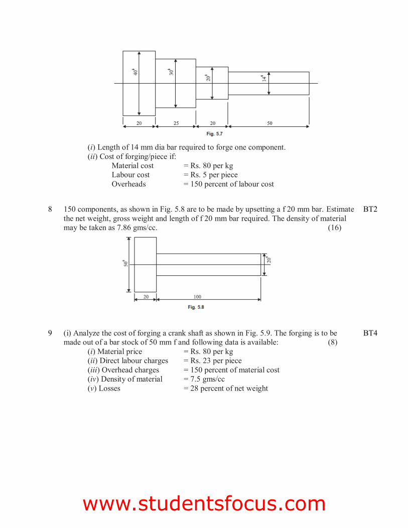
(i) Length of 14 mm dia bar required to forge one component. (ii) Cost of forging/piece if:
Material cost = Rs. 80 per kg Labour cost = Rs. 5 per piece Overheads = 150 percent of labour cost
8 150 components, as shown in Fig. 5.8 are to be made by upsetting a f 20 mm bar. Estimate
the net weight, gross weight and length of f 20 mm bar required. The density of material may be taken as 7.86 gms/cc. (16)
BT2
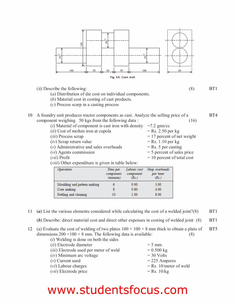
9 (i) Analyze the cost of forging a crank shaft as shown in Fig. 5.9. The forging is to be made out of a bar stock of 50 mm f and following data is available: (8)
(i) Material price = Rs. 80 per kg (ii) Direct labour charges = Rs. 23 per piece (iii) Overhead charges = 150 percent of material cost (iv) Density of material = 7.5 gms/cc (v) Losses = 28 percent of net weight
BT4
www.studentsfocus.com
(ii) Describe the following: (8) (a) Distribution of die cost on individual components. (b) Material cost in costing of cast products. (c) Process scarp in a casting process
BT1
10 A foundry unit produces tractor components as cast. Analyze the selling price of a component weighing 50 kgs from the following data : (16)
(i) Material of component is cast iron with density =7.2 gms/cc (ii) Cost of molten iron at cupola = Rs. 2.50 per kg (iii) Process scrap = 17 percent of net weight (iv) Scrap return value = Rs. 1.10 per kg (v) Administrative and sales overheads = Rs. 5 per casting (vi) Agents commission = 5 percent of sales price (vii) Profit = 10 percent of total cost (viii) Other expenditure is given in table below:
BT4
11 (a) List the various elements considered while calculating the cost of a welded joint?(8) BT1
(b) Describe: direct material cost and direct other expenses in costing of welded joint (8) BT1
12 (a) Evaluate the cost of welding of two plates 100 × 100 × 8 mm thick to obtain a plate of dimensions 200 ×100 × 8 mm. The following data is available: (8)
(i) Welding is done on both the sides (ii) Electrode diameter = 5 mm (iii) Electrode used per meter of weld = 0.500 kg (iv) Minimum arc voltage = 30 Volts (v) Current used = 225 Amperes (vi) Labour charges = Rs. 10/meter of weld (vii) Electrode price = Rs. 10/kg
BT5
www.studentsfocus.com
(viii) Efficiency of welding machine = 50 percent (ix) Welding speed = 2 meters/hour (x) Ratio of operating to connecting time = 1.5
(b) Evaluate the cost of filler material and gases consumed in welding of two plates 8 mm thick and 1.5 m long. Gas cutting is used to make 60°-V on the edges of both the plates. The cost of Oxygen is Rs. 10 per cu meter and cost of acetylene is Rs. 5 per cu meter. The filler rod costs Rs. 6.50/kg. Take other data from the tables. Density of filler metal is 10 gms/cc. (8)
BT5
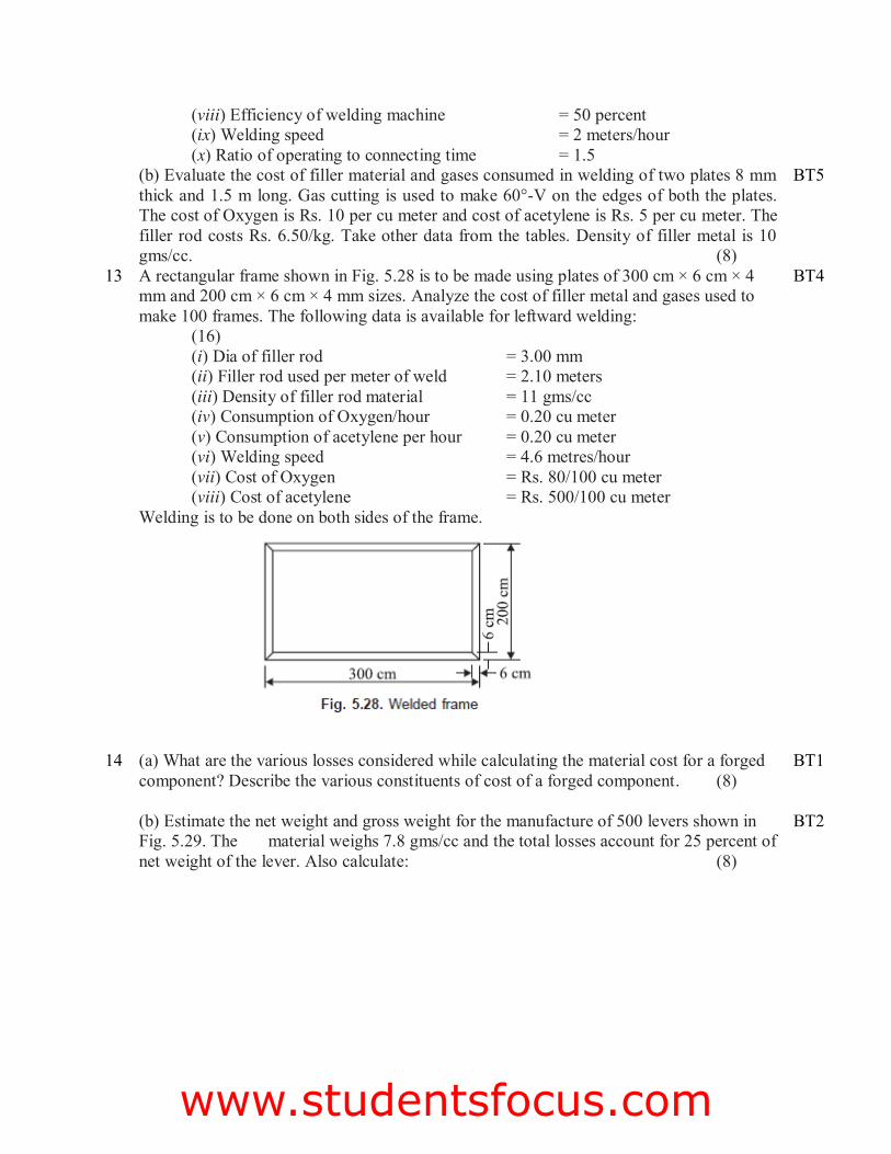
13 A rectangular frame shown in Fig. 5.28 is to be made using plates of 300 cm × 6 cm × 4 mm and 200 cm × 6 cm × 4 mm sizes. Analyze the cost of filler metal and gases used to make 100 frames. The following data is available for leftward welding: (16) (i) Dia of filler rod = 3.00 mm (ii) Filler rod used per meter of weld = 2.10 meters (iii) Density of filler rod material = 11 gms/cc (iv) Consumption of Oxygen/hour = 0.20 cu meter (v) Consumption of acetylene per hour = 0.20 cu meter (vi) Welding speed = 4.6 metres/hour (vii) Cost of Oxygen = Rs. 80/100 cu meter (viii) Cost of acetylene = Rs. 500/100 cu meter Welding is to be done on both sides of the frame.
BT4
14 (a) What are the various losses considered while calculating the material cost for a forged component? Describe the various constituents of cost of a forged component. (8)
BT1
(b) Estimate the net weight and gross weight for the manufacture of 500 levers shown in Fig. 5.29. The material weighs 7.8 gms/cc and the total losses account for 25 percent of net weight of the lever. Also calculate: (8)
BT2
www.studentsfocus.com
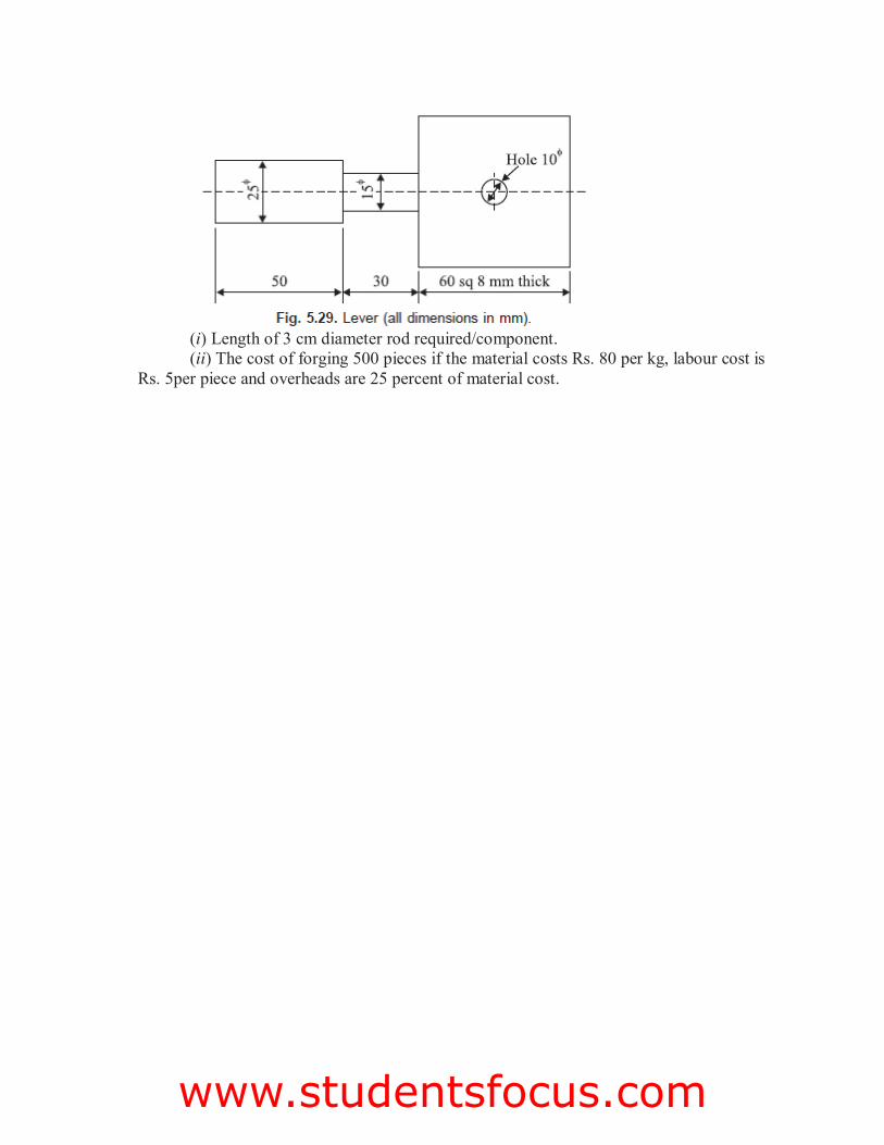
(i) Length of 3 cm diameter rod required/component. (ii) The cost of forging 500 pieces if the material costs Rs. 80 per kg, labour cost is
Rs. 5per piece and overheads are 25 percent of material cost.
www.studentsfocus.com
UNIT – V
INTRODUCTION TO COST ESTIMATION
PART – A (2 marks)
1 Define cycle time. BT1 2 List various factors affecting cutting speed. BT1 3 How will you calculate the time required for drilling a hole in an object? BT3 4 Estimate the milling time to cut 60 teeth on a gear blank 60 mm thick; feed 35
mm/min and take overall set up time as 10 minutes BT2
5 Calculate the time required for turning operation BT3 6 List the major objectives in machining industries? BT1 7 Discuss briefly about the necessities to determine the actual machining time? BT1 8 List the major factors to be considered for selecting cutting velocity for machining
operations? BT1
9 List the major factors to be considered for selecting value of feed for machining operations? BT1
10 Differentiate length of cut and depth of cut BT2 11 Define machining time. BT1 12 Explain briefly the types of machining processes in the machine shop BT4 13 Define spot facing BT1 14 Explain briefly about boring BT4 15 Give the formula for estimation of machining time for drilling BT2 16 Differentiate planer and shaper BT2 17 Give the types of grinding machine BT2 18 Define Set-up time BT1 19 Differentiate horizontal and vertical milling BT2 20 Explain briefly about handling time in machining BT5
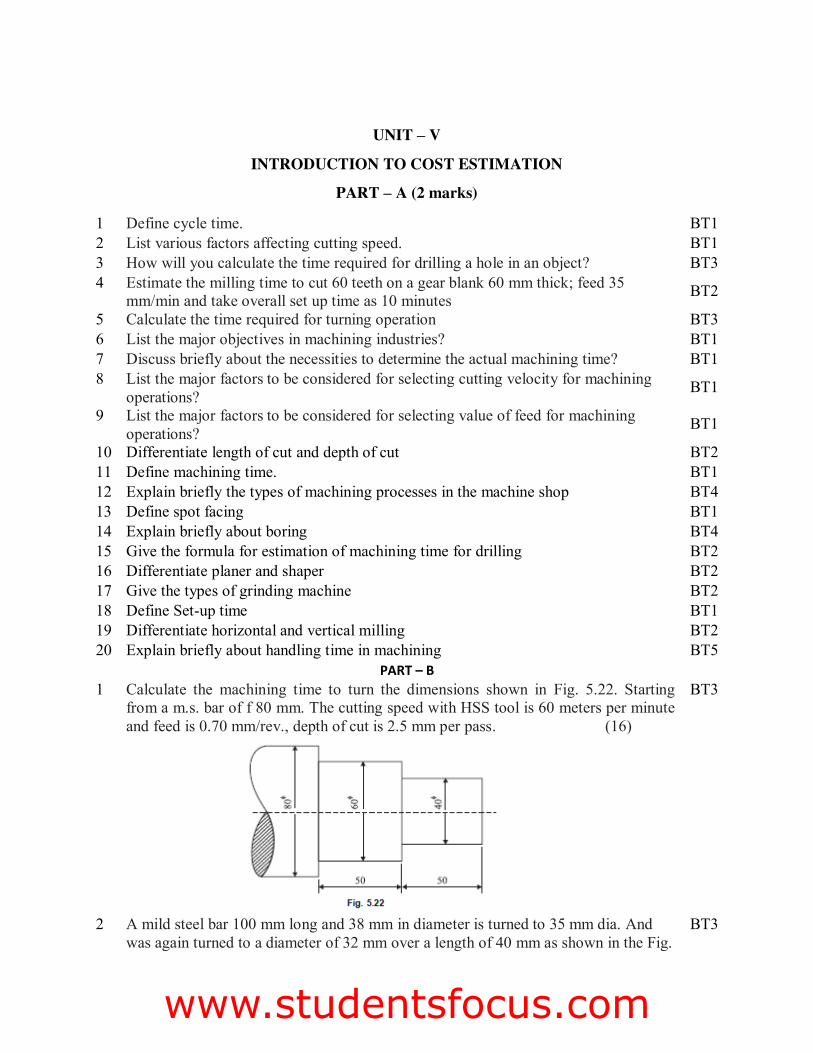
PART – B 1 Calculate the machining time to turn the dimensions shown in Fig. 5.22. Starting
from a m.s. bar of f 80 mm. The cutting speed with HSS tool is 60 meters per minute and feed is 0.70 mm/rev., depth of cut is 2.5 mm per pass. (16)
BT3
2 A mild steel bar 100 mm long and 38 mm in diameter is turned to 35 mm dia. And was again turned to a diameter of 32 mm over a length of 40 mm as shown in the Fig.
BT3
www.studentsfocus.com
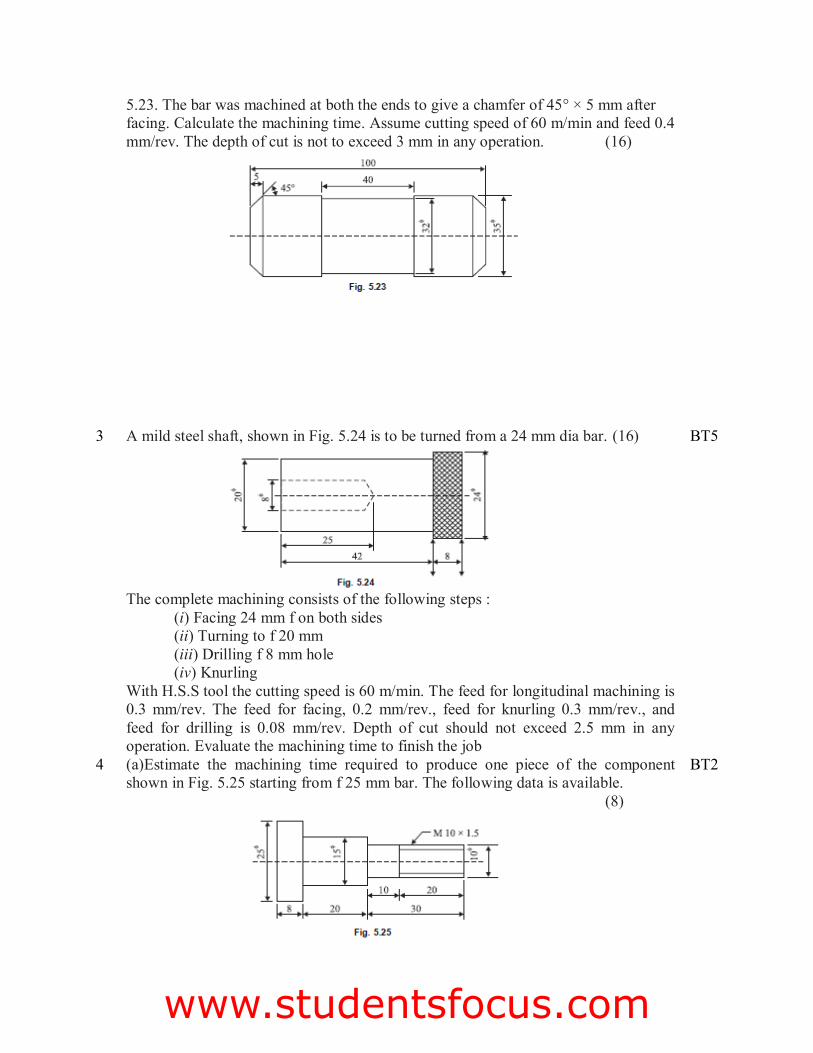
5.23. The bar was machined at both the ends to give a chamfer of 45° × 5 mm after facing. Calculate the machining time. Assume cutting speed of 60 m/min and feed 0.4 mm/rev. The depth of cut is not to exceed 3 mm in any operation. (16)
3 A mild steel shaft, shown in Fig. 5.24 is to be turned from a 24 mm dia bar. (16)
The complete machining consists of the following steps :
(i) Facing 24 mm f on both sides (ii) Turning to f 20 mm (iii) Drilling f 8 mm hole (iv) Knurling
With H.S.S tool the cutting speed is 60 m/min. The feed for longitudinal machining is 0.3 mm/rev. The feed for facing, 0.2 mm/rev., feed for knurling 0.3 mm/rev., and feed for drilling is 0.08 mm/rev. Depth of cut should not exceed 2.5 mm in any operation. Evaluate the machining time to finish the job
BT5
4 (a)Estimate the machining time required to produce one piece of the component shown in Fig. 5.25 starting from f 25 mm bar. The following data is available. (8)
BT2
www.studentsfocus.com
For turning: Cutting speed = 40 m/min. Feed = 0.4 mm/rev. Depth of cut = 2.5 mm/per pass
For thread cutting: Cutting speed = 8 m/min.
(b) Estimate the time taken to drill a 25 mm dia × 10 cm deep hole in a casting. First a 10 mm dia drill is used and then the hole is enlarged by a 25 mm dia drill. Assume:
Cutting speed = 15 m/min. (8) Feed for f 10 mm drill = 0.22 mm/rev. Feed for f 25 mm drill = 0.35 mm/rev.
BT2
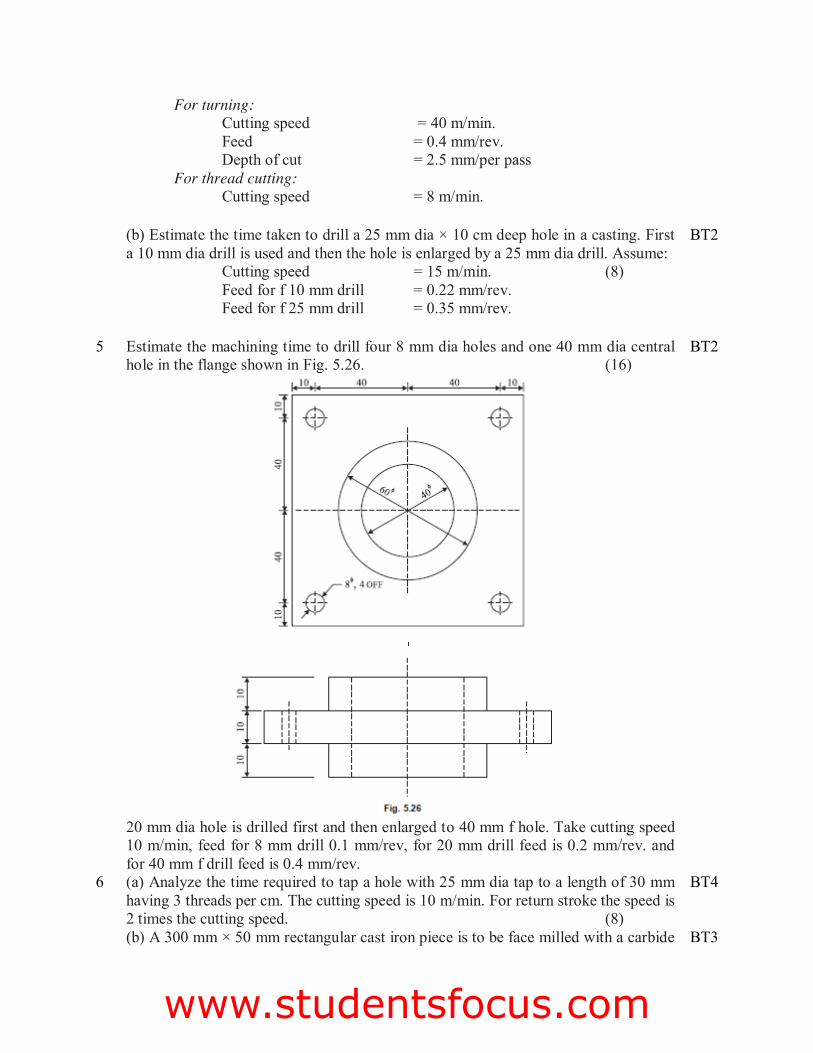
5 Estimate the machining time to drill four 8 mm dia holes and one 40 mm dia central hole in the flange shown in Fig. 5.26. (16)
20 mm dia hole is drilled first and then enlarged to 40 mm f hole. Take cutting speed 10 m/min, feed for 8 mm drill 0.1 mm/rev, for 20 mm drill feed is 0.2 mm/rev. and for 40 mm f drill feed is 0.4 mm/rev.
BT2
6 (a) Analyze the time required to tap a hole with 25 mm dia tap to a length of 30 mm having 3 threads per cm. The cutting speed is 10 m/min. For return stroke the speed is 2 times the cutting speed. (8)
BT4
(b) A 300 mm × 50 mm rectangular cast iron piece is to be face milled with a carbide BT3
www.studentsfocus.com
cutter. The cutting speed and feed are 50 m/min and 50 mm/min. If the cutter dia is 80 mm and it has 12 cutting teeth, calculate: (8)
(i) Cutter r.p.m. (ii) Feed per tooth (iii) Milling time
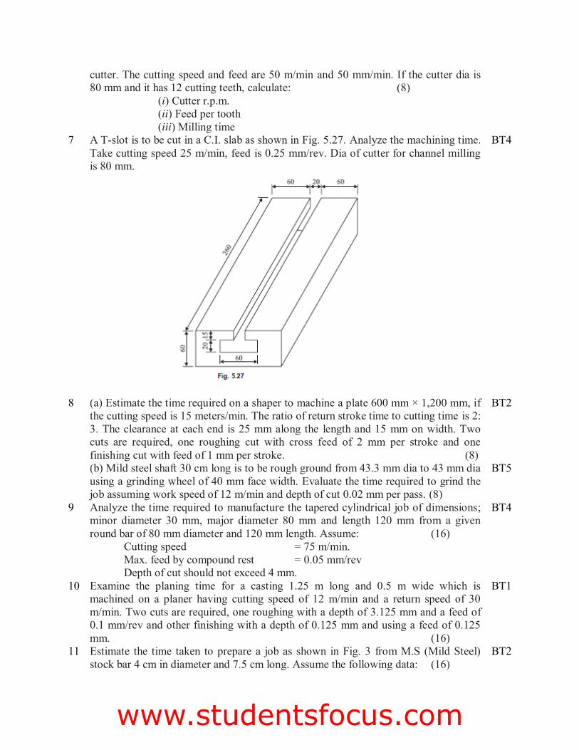
7 A T-slot is to be cut in a C.I. slab as shown in Fig. 5.27. Analyze the machining time. Take cutting speed 25 m/min, feed is 0.25 mm/rev. Dia of cutter for channel milling is 80 mm.
BT4
8 (a) Estimate the time required on a shaper to machine a plate 600 mm × 1,200 mm, if the cutting speed is 15 meters/min. The ratio of return stroke time to cutting time is 2: 3. The clearance at each end is 25 mm along the length and 15 mm on width. Two cuts are required, one roughing cut with cross feed of 2 mm per stroke and one finishing cut with feed of 1 mm per stroke. (8)
BT2
(b) Mild steel shaft 30 cm long is to be rough ground from 43.3 mm dia to 43 mm dia using a grinding wheel of 40 mm face width. Evaluate the time required to grind the job assuming work speed of 12 m/min and depth of cut 0.02 mm per pass. (8)
BT5
9 Analyze the time required to manufacture the tapered cylindrical job of dimensions; minor diameter 30 mm, major diameter 80 mm and length 120 mm from a given round bar of 80 mm diameter and 120 mm length. Assume: (16)
Cutting speed = 75 m/min. Max. feed by compound rest = 0.05 mm/rev Depth of cut should not exceed 4 mm.
BT4
10 Examine the planing time for a casting 1.25 m long and 0.5 m wide which is machined on a planer having cutting speed of 12 m/min and a return speed of 30 m/min. Two cuts are required, one roughing with a depth of 3.125 mm and a feed of 0.1 mm/rev and other finishing with a depth of 0.125 mm and using a feed of 0.125 mm. (16)
BT1
11 Estimate the time taken to prepare a job as shown in Fig. 3 from M.S (Mild Steel) stock bar 4 cm in diameter and 7.5 cm long. Assume the following data: (16)
BT2
www.studentsfocus.com
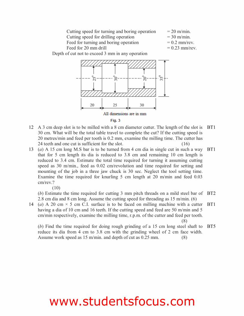
Cutting speed for turning and boring operation = 20 m/min. Cutting speed for drilling operation = 30 m/min. Feed for turning and boring operation = 0.2 mm/rev. Feed for 20 mm drill = 0.23 mm/rev.
Depth of cut not to exceed 3 mm in any operation
12 A 3 cm deep slot is to be milled with a 8 cm diameter cutter. The length of the slot is
30 cm. What will be the total table travel to complete the cut? If the cutting speed is 20 metres/min and feed per tooth is 0.2 mm, examine the milling time. The cutter has 24 teeth and one cut is sufficient for the slot. (16)
BT1
13 (a) A 15 cm long M.S bar is to be turned from 4 cm dia in single cut in such a way that for 5 cm length its dia is reduced to 3.8 cm and remaining 10 cm length is reduced to 3.4 cm. Estimate the total time required for turning it assuming cutting speed as 30 m/min., feed as 0.02 cm/revolution and time required for setting and mounting of the job in a three jaw chuck is 30 sec. Neglect the tool setting time. Examine the time required for knurling 5 cm length at 20 m/min and feed 0.03 cm/rev.? (10)
BT1
(b) Estimate the time required for cutting 3 mm pitch threads on a mild steel bar of 2.8 cm dia and 8 cm long. Assume the cutting speed for threading as 15 m/min. (6)
BT2
14 (a) A 20 cm × 5 cm C.I. surface is to be faced on milling machine with a cutter having a dia of 10 cm and 16 teeth. If the cutting speed and feed are 50 m/min and 5 cm/min respectively, examine the milling time, r.p.m. of the cutter and feed per tooth. (8)
BT1
(b) Find the time required for doing rough grinding of a 15 cm long steel shaft to reduce its dia from 4 cm to 3.8 cm with the grinding wheel of 2 cm face width. Assume work speed as 15 m/min. and depth of cut as 0.25 mm. (8)
BT5
www.studentsfocus.com