Department of Forensic Science Training Manual, provides the basis for effective quality management...
94
240-D100 FX-TM Procedures Manual Qualtrax ID: 2986 Issued by Physical Evidence Program Manager Qualtrax Revision 6 Issue Date: 25-April-2018 Page 1 of 94 Department of Forensic Science FIREARM/TOOLMARK PROCEDURES MANUAL UNCONTROLLED COPY COPYRIGHT © 2018 VIRGINIA DEPARTMENT OF FORENSIC SCIENCE
Transcript of Department of Forensic Science Training Manual, provides the basis for effective quality management...
240-D100 FX-TM Procedures Manual Qualtrax ID: 2986Issued by Physical Evidence Program Manager Qualtrax Revision 6Issue Date: 25-April-2018 Page 1 of 94
Department of Forensic Science
FIREARM/TOOLMARK PROCEDURES MANUAL
UNCONTROLLED COPY
COPYRIGHT © 2018
VIRGINIA DEPARTMENT
OF FORENSIC SCIENCE

Table of Contents
240-D100 FX-TM Procedures Manual Qualtrax ID: 2986Issued by Physical Evidence Program Manager Qualtrax Revision 6Issue Date: 25-April-2018 Page 2 of 94
TABLE OF CONTENTS Introduction 1 Physical Examination and Classification of Firearms
1.1 Introduction 1.2 Safety Considerations 1.3 Instrumentation 1.4 Minimum Analytical Standards and Controls 1.5 Procedure or Analysis 1.6 References
2 Physical Examination and Classification of Fired Bullet Evidence
2.1 Introduction 2.2 Safety Considerations 2.3 Instrumentation 2.4 Minimum Analytical Standards and Controls 2.5 Procedure or Analysis 2.6 References
3 Physical Examination and Classification of Cartridges and Fired Cartridge Cases
3.1 Introduction 3.2 Safety Considerations 3.3 Instrumentation 3.4 Minimum Analytical Standards and Controls 3.5 Procedure or Analysis 3.6 References
4 Physical Examination and Classification of Shotshells and Fired Shotshell Cases
4.1 Introduction 4.2 Safety Considerations 4.3 Instrumentation 4.4 Minimum Analytical Standards and Controls 4.5 Procedure or Analysis 4.6 References
5 Microscopic Comparison
5.1 Introduction 5.2 Safety Considerations 5.3 Preparation 5.4 Instrumentation 5.5 Minimum Analytical Standards and Controls 5.6 Procedure or Analysis 5.7 References
6 National Integrated Ballistic Information Network (NIBIN)
6.1 Introduction 6.2 Safety Considerations 6.3 Instrumentation 6.4 Minimum Analytical Standards and Controls
UNCONTROLLED COPY
COPYRIGHT © 2018
VIRGINIA DEPARTMENT
OF FORENSIC SCIENCE

Table of Contents
240-D100 FX-TM Procedures Manual Qualtrax ID: 2986Issued by Physical Evidence Program Manager Qualtrax Revision 6Issue Date: 25-April-2018 Page 3 of 94
6.5 Procedure or Analysis 6.6 References
7 Range Determination
7.1 Introduction 7.2 Safety Considerations 7.3 Preparation 7.4 Instrumentation 7.5 Minimum Analytical Standards and Controls 7.6 Procedure or Analysis 7.7 References
8 Physical Examination and Classification of Toolmarks
8.1 Introduction 8.2 Safety Considerations 8.3 Instrumentation 8.4 Minimum Analytical Standards and Controls 8.5 Procedure or Analysis 8.6 References
9 Number Restoration
9.1 Introduction 9.2 Safety Considerations 9.3 Preparation 9.4 Instrumentation 9.5 Minimum Analytical Standards and Controls 9.6 Procedure or Analysis 9.7 References
10 Fracture Match Examination
10.1 Introduction 10.2 Safety Considerations 10.3 Instrumentation 10.4 Minimum Analytical Standards and Controls 10.5 Procedure or Analysis 10.6 References
11 Verification/Blind Verification
11.1 Introduction 11.2 Verification Requirements 11.3 Verification Documentation Requirements 11.4 Blind Verification Requirements
12 Quality Assurance
12.1 Introduction 12.2 Reagents 12.3 Balances 12.4 Comparison Microscopes 12.5 Stereo Microscopes 12.6 Micrometers and Calipers 12.7 Rulers and Tape Measures
UNCONTROLLED COPY
COPYRIGHT © 2018
VIRGINIA DEPARTMENT
OF FORENSIC SCIENCE

Table of Contents
240-D100 FX-TM Procedures Manual Qualtrax ID: 2986Issued by Physical Evidence Program Manager Qualtrax Revision 6Issue Date: 25-April-2018 Page 4 of 94
12.8 Arsenal Weights 12.9 U.S Department of Justice General Rifling Characteristics Software 12.10 NIBIN System Performance Check 12.11 Reference Collections
13 Uncertainty Elements
13.1 Scope 13.2 Documentation 13.3 Estimating the Uncertainty of Measurement 13.4 UoM Review 13.5 Measurement Assurance 13.6 References
14 Report Formats
14.1 Introduction 14.2 Firearm Functioning 14.3 Test Fires/Tests and Disposition (NIBIN and Comparison) 14.4 Resubmission of Test Fired Ammunition Components 14.5 Trigger Pull 14.6 Barrel/Overall Length 14.7 Non-Functioning Firearm/Instrument 14.8 Magazine/Firearm Capacity 14.9 Firearm Parts 14.10 Cartridges/Shotshells 14.11 Fired Ammunition Components 14.12 NIBIN 14.13 Toolmarks 14.14 Mechanical Testing 14.15 Distance Determination Examinations 14.16 Fracture Matching 14.17 Number Restoration
Appendix A: Abbreviations Appendix B: Code 39 Barcode Appendix C: Reagents
UNCONTROLLED COPY
COPYRIGHT © 2018
VIRGINIA DEPARTMENT
OF FORENSIC SCIENCE
Introduction
240-D100 FX-TM Procedures Manual Qualtrax ID: 2986Issued by Physical Evidence Program Manager Qualtrax Revision 6Issue Date: 25-April-2018 Page 5 of 94
INTRODUCTION The information in this Procedures Manual was collected from the Association of Firearm and Tool Mark Examiners (AFTE) Procedures Manual and other sources. It is presented here for easy reference for Firearm/Toolmark Examiners. This manual presents a basic outline of procedures most routinely used to analyze evidence submitted to the Firearm/Toolmark Section of the Virginia Department of Forensic Science (DFS). This manual, in combination with the Section Training Manual, provides the basis for effective quality management of analysis. The Department’s Quality Manual (QM) provides additional guidelines. Every case is unique and must be evaluated by the individual examiner. Not all possible analyses that may be encountered in casework can be appropriately covered in a procedures manual nor can all possible variations to a described procedure be included. It is always the examiner’s responsibility to choose the best analytical scheme for each individual case, particularly for evidence not routinely encountered. It is expected that Section Supervisors shall be consulted, and the Physical Evidence Program Manager shall be notified of deviations from existing procedures in accordance with the Department of Forensic Science Quality Manual. New methods must be validated before use. Published methods must be verified to work in each Regional Laboratory before use. Prior to beginning a validation process, consult the Section Supervisor who shall consult with the Physical Evidence Program Manager for determination and approval of an appropriate validation plan. Examination Documentation Worksheets are provided as controlled forms. There may be times, however, when plain paper may be useful for additional note taking. This is an acceptable practice as long as the evidence description and pertinent information regarding tests performed are recorded. Examination records shall include each examination activity conducted, to include the sequence and results of each, which will allow for another examiner to evaluate the data, interpret the results and come to the same conclusion and also be able to repeat the various steps used by the examiner in the analysis under conditions as close as possible to the original. When recording a measurement, the value displayed on the device shall be recorded in its entirety. Internet references included in examination documentation shall, at a minimum, contain the website address and the date accessed/printed. The examination documentation shall contain documentation as to the types of materials that are generated during the analysis. Tests, casts and test patterns produced during analysis shall be considered evidence. Tests produced from laboratory materials will be created in LIMS, listed on the Request for Laboratory Examination form (RFLE) and on the Certificate of Analysis (CoA) as sub-items of the tool or medium from which they were produced. Documentation shall be on the RFLE, indicating the container in which the tests are being returned, in addition this information will be included on the CoA. There are no specific environmental factors, outside those provided in a standard laboratory facility, which would influence the quality of the test results. Examination documentation shall reflect, at a minimum, the starting and ending date of the examination. All evidence shall be marked in accordance with the QM. Evidence Storage Short term storage is used when evidence is in the process of examination or is waiting for instrumental support results. Evidence generally will not remain in short term storage for longer than 90 days. After this time period, evidence must be placed into long term storage according to the QM.
UNCONTROLLED COPY
COPYRIGHT © 2018
VIRGINIA DEPARTMENT
OF FORENSIC SCIENCE

Introduction
240-D100 FX-TM Procedures Manual Qualtrax ID: 2986Issued by Physical Evidence Program Manager Qualtrax Revision 6Issue Date: 25-April-2018 Page 6 of 94
Trace Evidence
Examine the item visually and microscopically for any trace material. Document the presence of possible blood, tissue, plaster, paint, hair, fiber, glass and/or other materials. Consult the RFLE or submitting agency to determine if further examination of trace material is necessary. Consult, if necessary, with the appropriate discipline prior to the removal and packaging of trace evidence. If the material IS NOT going to be retained for further examination, proceed with the following, as necessary: For evidence containing blood, tissue, or other biohazards, as practical based on evidence type and size, place the
evidence into an appropriate beaker containing a 10% bleach solution (refer to Section 12 for solution preparation) to soak for at least one (1) minute, followed with water rinse.
Use of an ultrasonic bath may assist with loosening debris more efficiently. Care should be taken when using an ultrasonic bath to minimize damage to the evidence.
Remove loosened material by rinsing with methanol or water. Remove plaster by soaking in a 15% Acetic Acid Solution (refer to Section 12 for solution preparation) or other
appropriate solution. Remove paint by soaking in alcohol, acetone or other appropriate solution. Use a non-abrasive brush to remove loose material. Use TergAZyme® for removal of tissue, Naval Jelly or E-zest cleaner to remove dark stains, as needed. Record steps taken and observations in examination documentation.
UNCONTROLLED COPY
COPYRIGHT © 2018
VIRGINIA DEPARTMENT
OF FORENSIC SCIENCE

1 Physical Examination and Classification of Firearms
240-D100 FX-TM Procedures Manual Qualtrax ID: 2986Issued by Physical Evidence Program Manager Qualtrax Revision 6Issue Date: 25-April-2018 Page 7 of 94
1 PHYSICAL EXAMINATION AND CLASSIFICATION OF FIREARMS 1.1 Introduction
All firearms must be treated as though they are loaded. It is the responsibility of the firearm examiner to ensure that all appropriate safety checks are performed on a firearm or item of ammunition prior to test firing.
1.2 Safety Considerations
The muzzle of the firearm must always be pointed in a safe direction. Firearms submitted to the laboratory for examination should be unloaded and in a safe condition; however,
the examiner must first safety check a weapon to ensure that it is unloaded before conducting any other examinations.
If a firearm is found to be loaded, the Supervisor shall be notified, and it shall be documented in the examination documentation.
A magazine received in a loaded condition must first be unloaded prior to conducting any examinations with it using a firearm.
Test firing or any examination of the firearm that utilizes ammunition or an ammunition component shall only be performed in designated test firing areas.
Firearms shall be fired in the manner in which they were designed. If it is not possible to fire the weapon from the shoulder or using standard hand positions, a remote firing device shall be used.
After the examination is completed, a safety appliance shall be placed in/through the action for return to the agency.
1.3 Instrumentation
Standard Trigger Weights Ruler, Tape Measure, Non-marring rigid rod Perspective Enterprises device Scale/Balance Stereo Microscope
1.4 Minimum Analytical Standards and Controls
Ensure the equipment utilized in the examination has been appropriately calibrated and/or performance checked prior to use. See Section 12 of this manual for specific requirement.
1.5 Procedure or Analysis
1.5.1 General, Visual, and Physical Examination
At a minimum, record the following firearm features: Caliber/Gauge Make/Model Serial number Operating condition GRC (number and direction) Record the following additional firearm features for comparison firearms: Firing mechanics Type of action Safeties and operability Land and groove measurements when a bullet comparison is performed
UNCONTROLLED COPY
COPYRIGHT © 2018
VIRGINIA DEPARTMENT
OF FORENSIC SCIENCE

1 Physical Examination and Classification of Firearms
240-D100 FX-TM Procedures Manual Qualtrax ID: 2986Issued by Physical Evidence Program Manager Qualtrax Revision 6Issue Date: 25-April-2018 Page 8 of 94
If submitted evidence cartridges are examined or used to generate test fires they shall be appropriately marked, documented in the examination documentation and the result listed on the CoA. It is acceptable to place non-examined evidence cartridges in a marked proximal container and document the number received and that no examination was conducted in the examination documentation and on the CoA.
1.5.2 Pre-Firing Safety Examination
A visual examination of firearm prior to test firing is needed to determine:
Possibility of bore obstruction Signs of cracks or weaknesses in major parts of frame, slide, or barrel Overall mechanism functioning Type of ammunition appropriate for use with firearm Suitability of evidence ammunition submitted for test firing Soundness of chamber/barrel, condition of percussion nipples, existing load in chamber
(muzzleloaders) If firearm should be test fired remotely due to unsafe firearm condition Record any deficiencies noted and observations on worksheet Check to ensure the firearm disconnects for semi-auto fire
1.5.3 Trigger-Pull Examination – Standard Trigger Weights
Trigger pull is defined as the amount of force which must be applied to the trigger of a firearm to cause sear release. The trigger pull of a firearm can be obtained utilizing standard trigger weights which make contact with the trigger at a point where the trigger finger would normally engage the trigger. The trigger pull of a firearm shall be reported in the CoA if the examination is performed.
1.5.3.1 Trigger Pull
Ensure that the firearm is unloaded and safeties are disabled. A fired cartridge case or “dummy” cartridge should be used to measure the trigger pull of
a rimfire firearm. The examination should not be performed on an empty chamber. Consider the potential for damage of a centerfire firearm and the use of a fired cartridge
case or “dummy” cartridge. For single-action trigger pull, cock the firearm. For double-action trigger pull, do not
cock the firearm. Hold the firearm so the barrel is vertical. Rest the trigger hook on the trigger, ensuring weights are parallel to the bore. Slowly lift the firearm upward with the trigger hook bringing force on the trigger.
o If the weights come off the flat surface without the sear releasing, add more weight to the trigger hook.
o If the sear releases before the weights come off the flat surface, remove weight from the trigger hook.
Continue until the least weight required to cause the sear to release is determined. Repeat the above, resetting the sear between each test. Record the weight used for each
test. Multiple tests should be performed to establish reproducibility within the range of values. Multiple measurements shall be taken for each chamber of a revolver. Record weight
used for each test. Contemporaneous documentation must be kept for each test result. The lightest weight that results in reliable sear release after multiple tests shall be
reported.
UNCONTROLLED COPY
COPYRIGHT © 2018
VIRGINIA DEPARTMENT
OF FORENSIC SCIENCE

1 Physical Examination and Classification of Firearms
240-D100 FX-TM Procedures Manual Qualtrax ID: 2986Issued by Physical Evidence Program Manager Qualtrax Revision 6Issue Date: 25-April-2018 Page 9 of 94
1.5.3.2 Interpretation of Results
The results acquired are only an approximation.
1.5.4 Barrel and Overall Length
Barrel length is defined as the distance between the muzzle end of the barrel and the face of the closed breechblock or bolt for firearms other than revolvers. On revolvers, it is the overall length of the barrel including the threaded portion within the frame. Overall length of a firearm is defined as the dimension measured parallel to the axis of the bore from muzzle to a line at right angles to the axis and tangent at the rearmost point of the butt plate or grip. Barrel length and overall length normally should include compensators, flash hiders, or any other permanently affixed attachments to the muzzle of a firearm. Removable barrel extensions, poly chokes, flash hiders, etc., are not included when measuring the barrel length or overall length.
The Perspective Enterprises device shall be used for measuring the overall and barrel length of firearms.
1.5.4.1 Barrel Length
Place a non-marring rigid rod into the barrel of the firearm with the action closed. Adjust the collar on the rod until it reaches the longest portion of the barrel. Remove the rod and align the breech end of the rod to the end of the measuring ruler on the device. Record the measurement at the edge of the collar that was flush with the longest barrel edge. Record measurements to the greater 1/16th of an inch (if the length falls between two marks on the ruler, record the higher value). Have the measurement verified by another examiner. It is acceptable to obtain the barrel length measurement for a revolver externally on the firearm. Measure the distance from the breech end of the barrel to the muzzle. Do not include the cylinder.
1.5.4.2 Overall Length
Place the firearm on the measuring platform with the butt of the firearm flush against the stationary gun stock piece. Ensure the barrel is parallel to the measuring ruler. Move the sliding muzzle piece until it is flush with the end of the barrel. Record the measurement observed at the “READ HERE” line on the sliding muzzle piece. Record measurements to the greater 1/16th of an inch (if the length falls between two marks on the ruler, record the higher value). Have the measurement verified by another examiner.
1.5.4.3 Interpretation of Results All measurements are reported in inches.
1.5.5 Test Firing
Test firing recovery methods include the water tank, the cotton-waste recovery box, the Detroit bullet trap, the snail system, and the bullet-trap range. The type of firearm and ammunition tested will usually dictate the type of recovery method used. In order to perform a microscopic comparison of a submitted firearm, a minimum of two (2) test shots should be fired and recovered. Other test firing procedures may include downloading ammunition and firing primed cartridges or shotshells.
Firearms with missing or broken parts may have to be test fired using parts from the reference collection. Document in notes the part utilized to test fire the questioned firearm along with the make, model, caliber and serial number or the tag number assigned to the reference firearm or magazine.
Documentation shall be included in the notes and on the CoA if the magazine submitted was used to obtain test fires or if a reference collection magazine was used.
UNCONTROLLED COPY
COPYRIGHT © 2018
VIRGINIA DEPARTMENT
OF FORENSIC SCIENCE

1 Physical Examination and Classification of Firearms
240-D100 FX-TM Procedures Manual Qualtrax ID: 2986Issued by Physical Evidence Program Manager Qualtrax Revision 6Issue Date: 25-April-2018 Page 10 of 94
Consideration should be given to indexing and sequencing each shot.
1.5.5.1 Safety Considerations Check the barrel for obstructions before firing Appropriate hearing and eye protection must be used Ensure the maximum velocity of the projectile is within the acceptable limits of the
particular water tank or bullet trap utilized Ensure the tank contains the proper water depth needed for firing Ensure that the exhaust fan or system and all warning systems are activated If a remote firing device is utilized, the examiner should be stationed behind a protective
shield or at a safe distance from the firearm when discharging the firearm
1.5.5.2 Water Recovery Tank
The water recovery tank is usually used to recover bullets from handguns, rifles, and slugs fired from shotguns. The cotton-waste recovery box utilizes similar procedures. Ensure that all lids or doors of the bullet recovery tank are closed and properly secured. No more than two (2) cartridges/shotshells should be loaded into the firearm during the
initial testing of the firearm. Test firing into the bullet recovery system shall be done with the muzzle of the firearm
inserted into the shooting tube so that any discharge from the muzzle will be captured within the recovery tank. o It is acceptable for the muzzle to be lined up with the shooting tube, but not inserted,
if the firearm is secured in the remote firing cart. Recover the bullets using an appropriate device. Ejected cartridge cases/shotshell cases must be retrieved.
1.5.5.3 Bullet-Trap Range
The bullet trap is usually used to test fire firearms when the recovery of the fired projectile(s) is not necessary. The Detroit bullet trap and the snail system utilize the same procedures.
No more than two (2) cartridges/shotshells are to be loaded into the firearm during the
initial testing of the firearm Fire the firearm into the front of the range trap Ejected cartridge cases/shotshell cases must be retrieved
1.5.5.4 Remote Firing
During the course of examining a firearm, it may be determined that it would be unsafe for the examiner to fire the firearm by holding it as designed. If it is necessary to obtain test standards from this firearm, the firearm should be fired remotely. The CyberNational Remote Firing Cart (or a similar device) can be utilized for firing long arms and some handguns. Set up the remote-firing device in front of the appropriate recovery system, as per
guidelines set forth by the device manufacturer Place firearm in device Dry-fire the firearm in the remote firing device before using ammunition The examiner should load no more than one (1) cartridge/shotshell into the firearm
during the initial testing of the firearm Activate the remote device while standing behind a protective shield or at a safe distance
away from the firearm Retrieve the test-fired components
UNCONTROLLED COPY
COPYRIGHT © 2018
VIRGINIA DEPARTMENT
OF FORENSIC SCIENCE

1 Physical Examination and Classification of Firearms
240-D100 FX-TM Procedures Manual Qualtrax ID: 2986Issued by Physical Evidence Program Manager Qualtrax Revision 6Issue Date: 25-April-2018 Page 11 of 94
1.5.5.5 Downloading Ammunition
It may be necessary to reduce the powder load of the cartridge in order to obtain a velocity suitable for safely collecting test-fired components for comparison purposes. Even with a reduced load, it may be necessary to fire the firearm remotely.
Remove the bullet from the cartridge using an inertia bullet puller or a reloading press Remove existing powder from the cartridge Weigh the pulled bullet To determine the velocity requirement for safe testing, consult a reloading manual, such
as Lyman, to determine the powder charge for the weight of the pulled bullet Weigh the powder in accordance with the velocity requirement Reload the cartridge with weighed powder that is not less than 30% of the original weight Loosely pack a small piece of tissue or other similar material into the cartridge case to fill
the gap between the bullet and powder Seat the bullet back into the cartridge case using a rubber mallet or a reloading press 50% downloading CANNOT be used with slow burning powders 50% downloading CANNOT be used with many non-canister powders Check the barrel for obstructions before each firing
1.5.5.6 Primed Cartridge/Shotshell Case
During the course of examining a firearm, it may be determined that it would be unsafe for the examiner to fire the firearm as received in its current condition. If it is not necessary to obtain test-fired components for comparison purposes, the firing condition of the firearm can be tested using a primed, empty cartridge case or shotshell case. Obtain a primed empty cartridge case in the desired caliber or pull the bullet of a
cartridge using an inertia bullet puller or reloading press, retaining only the primed cartridge case
For shotguns, obtain a primed empty shotshell case in the desired gauge or cut open a shotshell removing all components, retaining only the primed shotshell
A commercial firing pin testing device may be used Load the primed, empty cartridge/shotshell case, or a commercial firing pin testing device
into the chamber of the firearm, and test fire in the designated test firing area When utilizing a primed, empty cartridge/shotshell case, it is imperative to check the
barrel for obstruction before each test fire Repeat if the firearm has more than one action Retrieve all test-fired components
1.5.5.7 Test Fired Ammunition Tests may be produced from submitted evidence ammunition or laboratory stock ammunition/components. Case documentation shall include the specific date(s) tests are generated. Tests shall be sealed in an appropriate container, (small envelope, plastic bag, specimen box) which shall be labeled in accordance with the Quality Manual and with the following information: firearm item #, firearm brand, model, caliber and serial number. Tests produced from laboratory stock ammunition shall be returned in the same container with the firearm which generated the tests. Tests from laboratory stock ammunition shall be listed as a sub-item of the firearm which generated them on the RFLE, in LIMS and on the CoA.
UNCONTROLLED COPY
COPYRIGHT © 2018
VIRGINIA DEPARTMENT
OF FORENSIC SCIENCE
1 Physical Examination and Classification of Firearms
240-D100 FX-TM Procedures Manual Qualtrax ID: 2986Issued by Physical Evidence Program Manager Qualtrax Revision 6Issue Date: 25-April-2018 Page 12 of 94
Tests made from evidence ammunition shall be returned in the same container in which the evidence cartridges/shotshells were received. Additional test fired components from laboratory stock ammunition may be retained in the laboratory for reference or training purposes. Refer to Section 12 of this manual for specific requirements related to reference collections.
1.5.6 Rusty Firearm Examination
Rusty firearms or those found in water, etc., may be submitted for examination. Immediate attention must be given to the firearms recovered from water to prevent further damage to the firearm. The examiner should instruct the agency that recovers the firearm to submit the firearm in a container of the fluid in which the firearm was found. If this is not practical, the agency can be instructed to immediately and thoroughly spray the firearm with a water-displacing product such as WD-40 or other similar product to prevent further deterioration. It should be noted that the firearm might be too rusted to be functional. An examiner must take all necessary precautions to ensure that the firearm is unloaded. If it cannot be readily verified as being unloaded, it must be examined in an area designated for the firing of firearms. Determining whether or not a firearm is unloaded may necessitate a complete disassembly, or, in some cases, destruction (e.g., cutting).
Determine to what extent restoring the firearm is possible (for test firing, for recovering
manufacturer information, serial number, etc.) Soak the firearm in penetrating oil, de-rusting solvents, or similar material to dissolve rust Periodically check the firearm until the firearm functions, or the desired information is recovered Clean the firearm with gun cleaning solvent, cleaning patches, and cloth (only a non-marring item
should be used down the barrel of a firearm)
1.5.7 Malfunctioning Firearm Examination
A firearm examiner may be called upon to examine a firearm to determine if the firearm will malfunction. Many of these cases will deal with the question: "Will the firearm fire without pulling the trigger?" In these instances it should be the goal of the examiner to acquire a detailed account of the incident, followed by a thorough examination and testing of the firearm. Examinations may include external and internal observations and striking or dropping the firearm in attempts to duplicate the incident as reported. The examiner should attempt to conduct examinations in a manner so as not to alter the firearm. However, there may be occasions when damage may occur. Any change to the firearm should be specifically documented in the examiner’s notes.
The following list of examinations should serve as a guideline.
1.5.7.1 Visual Condition of Firearm as Received
Cocked/uncocked Safety position Loaded/unloaded Cartridge position Stuck cartridge/discharged cartridge cases Presence and/or location of flares
1.5.7.2 Visual abnormalities
Barrel (loose, damaged etc.) Receiver (condition) Slide (condition) Parts broken or missing (firing pin, ejector, extractor) Screws (loose or missing)
UNCONTROLLED COPY
COPYRIGHT © 2018
VIRGINIA DEPARTMENT
OF FORENSIC SCIENCE

1 Physical Examination and Classification of Firearms
240-D100 FX-TM Procedures Manual Qualtrax ID: 2986Issued by Physical Evidence Program Manager Qualtrax Revision 6Issue Date: 25-April-2018 Page 13 of 94
Alterations or adaptations Sights
1.5.7.3 Action - External
Relationships of the action parts Correct assembly The proper locking of the action on closing Cylinder rotation (securely locks) Hand relationship to the ratchet Trigger (not returning, sticks, broken spring, etc.) Trigger pull (single action, double action) and striking of hammer
1.5.7.4 Safeties
¼, ½, full cock, seating check (any false seating positions, pull off/push off, etc.) Function (grip, magazine, disconnector) Rebound hammer or inertia firing pin Firing pin (relationship to primer, condition) Drop hammer several times to check safeties Position of the slide or bolt in order to fire Condition of safeties
1.5.7.5 Action Check
Check feeding of magazine (lips, follower), carrier or lifter, and feed ramp Slam fire Extractor and/or ejector markings on evidence cartridges/discharged cartridge cases Marks exhibited on the cartridges/discharged cartridge cases Check for any inherent “quirks” known about the particular firearm based on literature or
case data
1.5.7.6 Test Fire Firearm
Note any operational problems Check the barrel for obstructions before each firing Misfires Ammunition involved (proper cartridge, type, reloads, etc.) Check consistency of the impression on test-fired components and evidence
1.5.7.7 Special Situational Tests
The examiner shall consult with the section supervisor and/or Firearms Technical Resource Team to devise a systematic approach for situational testing prior to a malfunctioning examination of the firearm. Tests can include, but are not limited to modified drop, jar off or rotational testing. The force to be used in testing could alter or damage internal parts and their working relationship(s). Firearms that are received in a damaged condition may require special situational tests, which may require more force than normal for an examination. Care should be exercised when testing a firearm to minimize examiner-caused damage that could prevent the determination of the cause of the reported malfunction.
1.5.7.8 Action-Internal
Hammer notches (worn, burrs, dirt, etc.) Sear (worn, broken, burrs, etc.)
UNCONTROLLED COPY
COPYRIGHT © 2018
VIRGINIA DEPARTMENT
OF FORENSIC SCIENCE

1 Physical Examination and Classification of Firearms
240-D100 FX-TM Procedures Manual Qualtrax ID: 2986Issued by Physical Evidence Program Manager Qualtrax Revision 6Issue Date: 25-April-2018 Page 14 of 94
Safeties (relationships and general parts relationship) Springs (weak, broken, altered, etc.) Signs of any tampering or faulty assembly
1.5.7.9 Interpretation of Results
If the primed case detonates, examine the major internal components to determine if there are any broken or missing parts. If the primed case does not detonate, this is an indication the firearm may not discharge when dropped, slammed, thrown down or falls due to improper storage.
1.5.8 Bore/Chamber Casting
Occasionally, firearms are received for which the caliber may not be known or may be different than is designated on the firearm and in the industry literature. In order to facilitate firing of test shots that are the correct caliber for a particular firearm, it may be necessary to make a bore and/or chamber cast. By measuring the cast, the correct cartridge can be determined for test firing. Casts can be made using various casting materials. Ensure that the firearm is not loaded Open the action and remove the bolt or bolt assembly Check the bore for obstruction Push a cleaning patch in the barrel, from muzzle end, until it is ½ inch to ¼ inch from the beginning
of the chamber Lubricate the chamber with gun oil, a silicone spray, or some other similar substance such as
WD40® Do not allow casting material to flow into breech as it will make extraction of the cast difficult When casting material is set or cool, depending on type used, gently tap end of cleaning rod to
loosen the cast from the chamber and then remove the cast from the breech end Use the same steps for casting the bore
1.5.8.1 Interpretation of Results
The correct caliber of the firearm can be determined by measuring the mouth, base, overall length, rim (if pertinent), shoulder length of the chamber cast, or the diameter of the bore cast.
Record the interpretation of results on an appropriate worksheet.
1.6 References
“A Guide to Firearms Safety”. A Safety and Educational Publication of the National Rifle Association. May 1994. Association of Firearm and Tool Mark Examiners Procedures Manual, 2001. Biasotti, A. A. “Vise/Rest for Remote Firing.” AFTE Journal. Vol. 11. No. 4. p. 16. “Bullet and Cartridge Case Recovery.” AFTE Journal. Vol. 16, No. 2, p.75. Code of Virginia §18.2-308.6 “Criteria for Evaluation of New Firearms Designs Under Conditions of Abusive Mishandling for the Use of Commercial Manufacturers”. American National Standards Institute Voluntary Industry Performance Standards ANSI/SAAMI Z299.5-1996. Newtown, CT: Sporting Arms and Ammunition Manufacturers’ Institute Inc. 1996.
UNCONTROLLED COPY
COPYRIGHT © 2018
VIRGINIA DEPARTMENT
OF FORENSIC SCIENCE

1 Physical Examination and Classification of Firearms
240-D100 FX-TM Procedures Manual Qualtrax ID: 2986Issued by Physical Evidence Program Manager Qualtrax Revision 6Issue Date: 25-April-2018 Page 15 of 94
DeForest, Gaensslen, and Lee. Forensic Science: An Introduction to Criminalistics. New York: McGraw Hill.1983. Denio, Dominic. “Making a Rusted Gun Functional.” AFTE Journal. Vol. 13. No. 3. p. 29. Gamboe, Tom. “MAFS Firearms Workshop: Trigger Pull Methods.” AFTE Journal. Vol. 18, No. 3, p. 77. Glossary of the Association of Firearm and Tool Mark Examiners, 5th ed. 2007. Haag, Michael, Stuart, Jay and Haag, Kim. “Ejection Patterning – Standard Testing and Effects of Non-Standard Angles, Orientations and Maneuvers,” AFTE Journal (2009) 41 (2): 111-129. Howe, Walter, J. “Laboratory Work Sheets.” AFTE Newsletter. No 2. August 1969. p. 13. http://www.swggun.org/guidelinedocs/guidelines_triggerpull.htm Lyman Reloading Handbook for Rifle, Pistol and Muzzle Loading. Lyman Gun Sight Products. Middlefield, Conn.1971. McBrayer, William S. “What? Another Water Tank and Bullet Stop!” AFTE Journal. Vol. 10. No. 2. p. 90. NRA Firearms Fact Book. National Rifle Association of America. 3rd ed. 1989. “New Ballistics Tank from Detroit-Armor Corporation Allows Fast Recovery Without Projectile Distortion.” AFTE Journal. Vol. 16, No. 3, p.106. Poole, Robert A. “Mikrosil Casting Material Information.” AFTE Journal. Vol. 15. No. 2, p. 80. “Reduced Powder Loads.” AFTE Newsletter. No. 3. p. 14. Rios, Ferdinand and Thornton, John. “Static vs. Dynamic Determination of Trigger Pull.” AFTE Journal. Vol. 16, No. 3, p. 84. “Safety On” CD, 1998. Speer Reloading Rifle and Pistol Manual. Blount Inc., Sporting Equipment Division. Lewiston, ID 1994. Striupaitis, Peter P. "Bore Casting Techniques for Caliber Designation of Rifles.” AFTE Journal. Vol. 15, No. 2, p. 88. “The Proper Method for Measuring Weapons.” AFTE Journal. Vol.14, No. 3, p. 10. Thompson, Roger C. “Firearms Malfunction Worksheets.” AFTE Journal. Vol. 15, No. 1, p. 100. U.S. Code Title 18, Chapter 44, Section 921, paragraph 24 (Gun Control Act of 1968) – can be accessed at http://www.nraila.org/federalfirearms.htm VA Department of Forensic Science Firearm/Toolmark Training Manual. www.afte.org
UNCONTROLLED COPY
COPYRIGHT © 2018
VIRGINIA DEPARTMENT
OF FORENSIC SCIENCE

2 Physical Examination and Classification of Fired Bullet Evidence
240-D100 FX-TM Procedures Manual Qualtrax ID: 2986Issued by Physical Evidence Program Manager Qualtrax Revision 6Issue Date: 25-April-2018 Page 16 of 94
2 PHYSICAL EXAMINATION AND CLASSIFICATION OF FIRED BULLET EVIDENCE 2.1 Introduction
The initial examination of any fired bullet evidence shall include the completion of a worksheet. These worksheets shall include the physical and damage description, which will serve as a source to document the condition of the evidence as received and any tests or comparisons performed.
2.2 Safety Considerations
Follow the procedures outlined in the Introduction section to clean evidence with appropriate solutions if biohazard material, blood or tissue is present.
2.3 Instrumentation Comparison Microscope Stereo Microscope Caliper/Micrometer/Ruler Scale/Balance Ammunition references
2.4 Minimum Analytical Standards and Controls
Ensure the equipment utilized in the examination has been appropriately calibrated and/or performance checked prior to use. See Section 12 of this manual for specific requirement.
2.5 Procedure or Analysis
2.5.1 General, Visual, Physical, and Trace Examinations
Record the following bullet features:
Caliber/gauge Bullet/slug weight (record weight of bullets in grains; record weight of slugs in ounces or grains) Number of land and groove impressions on a fired bullet Direction of twist Measured width of the land impressions (refer to Section 2.5.3) Measured width of the groove impressions (refer to Section 2.5.3) Measured diameter Bullet composition Bullet style Possible manufacturer/marketer of the bullet/projectile, if needed use reference materials (i.e.,
ammunition database) and indicate in notes the number assigned to this reference Description of the base of the bullet Type and position of cannelures Any extraneous markings to include flared base, skid marks, shave marks, and other marks Condition of the fired evidence as received Suitability of the fired evidence for comparison purposes GRC Search for possible firearms from which bullet was fired (refer to Section 2.5.4) As appropriate, compare marks on bullets with tests from a firearm or with other bullets (see Section
5)
UNCONTROLLED COPY
COPYRIGHT © 2018
VIRGINIA DEPARTMENT
OF FORENSIC SCIENCE

2 Physical Examination and Classification of Fired Bullet Evidence
240-D100 FX-TM Procedures Manual Qualtrax ID: 2986Issued by Physical Evidence Program Manager Qualtrax Revision 6Issue Date: 25-April-2018 Page 17 of 94
2.5.2 Caliber Determination
Caliber is one of the class characteristics of a fired bullet and is written as a numerical term that may be depicted with or without a decimal point. The determination of caliber will aid the examiner during the identification or elimination of a suspect firearm. If no firearm is submitted, the bullet's caliber may be used in determining the General Rifling Characteristics of the firearm involved. The following may be utilized to determine the caliber of any fired bullet. The condition of the bullet will determine which steps can be used: Compare the diameter of the evidence bullet directly with known fired test standards Measure the diameter of the evidence bullet using a measuring device and compare this
measurement with known measurements published in reference literature Determine the number and widths of the land and groove impressions and compare to the applicable
table in the current edition of the AFTE glossary. Determine the widths of one land and groove impression, and multiply by the number of land and
groove impressions to obtain the circumference. Use the mathematical formula C=πd to determine the diameter of the bullet
Physical characteristics of the evidence bullet, such as weight, bullet shape, composition, nose configuration, and number and placement of cannelures, may aid in caliber determination
2.5.3 Methods of Measuring Land and Groove Impressions
One of the class characteristics used in the discipline of firearm identification is the width of the land impressions and groove impressions. These measurements may aid the examiner during the identification or elimination of a suspect firearm. If no firearm is submitted, these measurements shall be used in determining the General Rifling Characteristics of the firearm involved. The measuring of land and groove impressions on a fired bullet can be accomplished by utilizing either the air-gap method or the stereo microscope reticle method. In measuring a fired bullet to determine the width of the land impression or the groove impression, it is paramount that the points used for beginning and ending a measurement comply with the discipline-wide practice. This practice utilizes the anchor points shown below.
Each available land and groove impression will be measured and recorded.
For multiple bullets having similar general rifling characteristics only one bullet needs to be measured. For bullets that are microscopically identified to tests produced with a firearm, at the discretion of the examiner, either the tests or questioned bullet(s) may be measured.
2.5.3.1 In the air gap method, the fired bullet in question is mounted on one stage of the comparison
microscope. The measuring device is mounted on the other stage. Both stages must be using the same magnification level (objective setting) and be in focus. Align the image of the land or groove impression with one of the anchor points corresponding with the anvil of the micrometer or measuring jaw of the caliper. Rotate the micrometer’s spindle to the next anchor point of the micrometer or the other jaw of the caliper to the land or
UNCONTROLLED COPY
COPYRIGHT © 2018
VIRGINIA DEPARTMENT
OF FORENSIC SCIENCE
2 Physical Examination and Classification of Fired Bullet Evidence
240-D100 FX-TM Procedures Manual Qualtrax ID: 2986Issued by Physical Evidence Program Manager Qualtrax Revision 6Issue Date: 25-April-2018 Page 18 of 94
groove impression and record the measurement gap (opening) displayed on the micrometer/caliper.
2.5.3.2 In the stereo microscope reticle method, the fired bullet in question is either held or mounted on a steady surface beneath the stereo microscope. The land or groove impression of the fired bullet is positioned with both of the anchor points corresponding to points on the alignment scale. Record the measurements observed on the scale. If performing the measurement at half magnification, it is necessary to multiply the value observed by two to obtain the correct measurement. The calculation shall be documented in the examination documentation.
2.5.4 FBI General Rifling Characteristics File (GRC)
The FBI's General Rifling Characteristics File (GRC) shall be utilized to determine a list of possible firearms that could have fired an evidence bullet. The search program available on the DFS Intranet in the Firearms Section shared folder shall be used for GRC search results.
A tolerance shall be added to the maximum and subtracted from the minimum using the criteria listed below to obtain the values for the search parameters. The maximum and minimum values will be rounded prior to applying the tolerances.
0.002 shall be used when the bullet exhibits crisp, defined rifling edges and/or minimal variance in measurements (0.002 or less) If the difference in the maximum and minimum values is 0.005 or greater, it is not necessary to apply a tolerance. 0.005 shall be used when rifling edges are rounded with no clear edge and/or there is some variance in measurements (greater than 0.002) The reason for the use of a tolerance larger than 0.005 shall be clearly documented in the case file.
The list generated shall be included in the examination documentation.
The phrase “too numerous to list” shall be used on the CoA when the list to be reported is greater than ten firearms. To justify the removal of a firearm(s) from the list to be reported, the examiner shall ensure that no such firearm(s) has been entered into the Department’s firearms database within the past twelve months. When utilized, the Department database summary report shall be included in the examination documentation. Any firearm(s) removed from the FBI GRC list shall be clearly delineated. A database will be maintained by the section of firearms submitted to the Department.
2.5.5 Interpretation of Results
Document if the item contains suitable markings for comparison with a firearm or with other fired components.
2.6 References
Association of Firearm and Tool Mark Examiners Procedures Manual, 2001. Barnes, Frank C. Cartridges of the World. 9th ed, 2000. Felix, Kyle. “Using Bullet Weights and Type to Determine Caliber and Brand,” AFTE Journal, 2008; 40(1): 64-80. Glossary of the Association of Firearm and Tool Mark Examiners, 5th ed. 2007.
UNCONTROLLED COPY
COPYRIGHT © 2018
VIRGINIA DEPARTMENT
OF FORENSIC SCIENCE
2 Physical Examination and Classification of Fired Bullet Evidence
240-D100 FX-TM Procedures Manual Qualtrax ID: 2986Issued by Physical Evidence Program Manager Qualtrax Revision 6Issue Date: 25-April-2018 Page 19 of 94
Howe, Walter, J. “Laboratory Work Sheets”. AFTE Newsletter. No. 2, August 1969, p. 13. Mathews, J. Howard. Firearms Identification Vol. I, 1973. Molnar, S. “A Simplified Technique for L&G Measurements”. AFTE Newsletter, No. 4, December 1969, p. 28. U.S. Department of Justice. Federal Bureau of Investigation. 1NCIC. Criminalistics Laboratory Information System (CLIS) Operating Manual. 2001 -2008. VA Department of Forensic Science Firearm/Toolmark Training Manual. Walsh, J. F. “Accuracy, Speed and Conversion in Rifling Measurements”. AFTE Journal. Vol. 9, No. 1, p. 50. www.afte.org www.firearmsid.com
UNCONTROLLED COPY
COPYRIGHT © 2018
VIRGINIA DEPARTMENT
OF FORENSIC SCIENCE

3 Physical Examination and Classification of Cartridges and Fired Cartridge Cases
240-D100 FX-TM Procedures Manual Qualtrax ID: 2986Issued by Physical Evidence Program Manager Qualtrax Revision 6Issue Date: 25-April-2018 Page 20 of 94
3 PHYSICAL EXAMINATION AND CLASSIFICATION OF CARTRIDGES AND FIRED CARTRIDGE CASES
3.1 Introduction
The initial examination of any fired cartridge case/cartridge evidence shall include the completion of a worksheet which shall include the physical description to document the condition of the evidence as received and any tests or comparisons performed.
3.2 Safety Considerations
Follow the procedures outlined in the Introduction section to clean evidence with appropriate solutions if biohazard material, blood or tissue is present.
3.3 Instrumentation
Comparison Microscope Stereo Microscope Micrometer/Caliper Ruler Scale/Balance
3.4 Minimum Analytical Standards and Controls
Ensure the equipment utilized in the examination has been appropriately calibrated and/or performance checked prior to use. See Section 12 of this manual for specific requirement.
3.5 Procedure or Analysis
The evidence shall be marked in such a way to protect characteristics which may be used for microscopic comparison.
3.5.1 General, Visual, Physical, and Trace Examinations
Record the following features:
Caliber The possible manufacturer/marketer of the cartridge case. If needed, use reference materials (i.e.,
ammunition database) and indicate in notes the number assigned to this reference. Description of metal used in cartridge case and primer Description of headstamp
3.5.2 Cartridge Component Verification
3.5.2.1 At times, a request may be made for examination of a cartridge for determination that its
composition meets the legal definitions of “ammunition” and “explosive material” as specified in the Code of Virginia. These examinations shall be documented in the “remarks” section of a cartridge worksheet.
The cartridge shall be disassembled Components shall be documented, including the type of powder
3.5.3 Caliber Determination
Caliber can usually be determined by examination of the headstamp of the cartridge/cartridge case. If the caliber cannot be determined from the headstamp, the cartridge case can be compared with laboratory
UNCONTROLLED COPY
COPYRIGHT © 2018
VIRGINIA DEPARTMENT
OF FORENSIC SCIENCE
3 Physical Examination and Classification of Cartridges and Fired Cartridge Cases
240-D100 FX-TM Procedures Manual Qualtrax ID: 2986Issued by Physical Evidence Program Manager Qualtrax Revision 6Issue Date: 25-April-2018 Page 21 of 94
standards, available manufacturer literature, or other appropriate references. Document in the notes the reference utilized to determine caliber.
3.5.4 Determination of Marks
Visual and microscopic examination of the cartridge/cartridge case may reveal a variety of markings. Types of marks that might be found may be as follows:
Breech face marks Extractor marks (clock position, if possible) Ejector marks (clock position, if possible) Resizing marks Chamber marks Anvil marks Magazine marks Ejection port marks Firing Pin Impression (class and individual characteristics) Firing Pin Drag Slide Scuff Mark (head @rim) Slide Drag Mark (wall) Other marks
As appropriate, compare marks on cartridge/cartridge case with tests from a firearm or with other cartridges/cartridge cases (see Section 5).
Any component markings that can be produced by cycling cartridges through the action of a firearm (chamber, extractor, ejector, other mechanism marks) shall not be reported as “fired in/from” marks unless it is has been determined through testing that marks having the same characteristics (depth, shape, individual detail, etc.) are produced only during the firing process. When the firearm is available, at least two cartridges should be cycled through the action to ensure they are fired in marks as opposed to cycle through the action marks.
Tests of cycled ammunition shall be treated as evidence. The method or procedure followed (steps taken) to produce cycling marks shall be documented in the case notes.
Only the above marks necessary to effect an identification or elimination are required to be photographed and/or described in examination documentation.
For inconclusive conclusions, all pertinent mechanism markings shall be evaluated and documented in the examination documentation.
3.5.5 Interpretation of Results
Document if the item contains suitable markings for comparison to determine identification with a firearm or with other ammunition components.
3.6 References
Association of Firearm and Tool Mark Examiners Procedures Manual, 2001. Code of Virginia §18.2-308.2(D). Glossary of the Association of Firearm and Tool Mark Examiners, 5th ed. 2007. Howe, Walter, J. “Laboratory Work Sheets”. AFTE Newsletter. No. 2, August 1969, p. 13.
UNCONTROLLED COPY
COPYRIGHT © 2018
VIRGINIA DEPARTMENT
OF FORENSIC SCIENCE

3 Physical Examination and Classification of Cartridges and Fired Cartridge Cases
240-D100 FX-TM Procedures Manual Qualtrax ID: 2986Issued by Physical Evidence Program Manager Qualtrax Revision 6Issue Date: 25-April-2018 Page 22 of 94
VA Department of Forensic Science Firearm/Toolmark Training Manual. www.afte.org
UNCONTROLLED COPY
COPYRIGHT © 2018
VIRGINIA DEPARTMENT
OF FORENSIC SCIENCE

4 Physical Examination and Classification of Shotshells and Fired Shotshell Cases
240-D100 FX-TM Procedures Manual Qualtrax ID: 2986Issued by Physical Evidence Program Manager Qualtrax Revision 6Issue Date: 25-April-2018 Page 23 of 94
4 PHYSICAL EXAMINATION AND CLASSIFICATION OF SHOTSHELLS AND FIRED SHOTSHELL CASES
4.1 Introduction
The initial examination of any evidence shotshell/shotshell case(s) or component(s) shall include the completion of a worksheet which shall include the physical description to document the condition of the evidence as received and any tests or comparisons performed. By examining wadding, the examiner may be able to determine the gauge size, manufacturer, and if the wad may possess markings suitable for comparison with the firearm that fired it. By examining recovered shot pellets, the examiner may be able to determine the actual shot size. The determined size can then be compared to the shot size loaded in submitted shotshells or to the size indicated by markings on the hull of the submitted shotshell case.
4.2 Safety Considerations
Follow the procedures outlined in the Introduction section to clean evidence with appropriate solutions if biohazard material, blood or tissue is present.
4.3 Instrumentation
Comparison Microscope Stereo Microscope Micrometer/Caliper Ruler Scale/Balance
4.4 Minimum Analytical Standards and Controls
Ensure the equipment utilized in the examination has been appropriately calibrated and/or performance checked prior to use. See Section 12 of this manual for specific requirement.
4.5 Procedure or Analysis
The evidence shall be marked in such a way to protect characteristics which may be used for microscopic comparison.
4.5.1 General, Visual, Physical, and Trace Examinations
Record the following features:
Gauge Possible manufacturer/marketer of the shotshell/shotshell case. If needed, use reference materials
(i.e., ammunition database) and indicate in notes the number assigned to this reference. Description of metal used in hull and primer Composition of hull (i.e., plastic/paper; color; ribbed/smooth) Description of headstamp
4.5.1.1 Shotshell/Shotshell Case Gauge Determination
Gauge can usually be determined by examination of the headstamp of the shotshell case. If it is not legible on the headstamp, the shotshell/shotshell case can be compared with laboratory reference materials (i.e., ammunition database) or available manufacturer literature. Record in notes the number assigned to the reference.
UNCONTROLLED COPY
COPYRIGHT © 2018
VIRGINIA DEPARTMENT
OF FORENSIC SCIENCE

4 Physical Examination and Classification of Shotshells and Fired Shotshell Cases
240-D100 FX-TM Procedures Manual Qualtrax ID: 2986Issued by Physical Evidence Program Manager Qualtrax Revision 6Issue Date: 25-April-2018 Page 24 of 94
4.5.1.2 Determination of Marks
Visual and microscopic examination of the shotshell/shotshell case may reveal a variety of markings. Types of marks that might be found may be as follows: Breech face marks Extractor marks Ejector marks Resizing marks Chamber marks Magazine marks Ejection port marks Markings on the exterior surface of hull Firing Pin Impression Firing Pin Drag Other marks
As appropriate, compare marks on shotshell/shotshell case with tests from a firearm or with other shotshell/shotshell cases.
Any component markings that can be produced by cycling shotshells through the action of a firearm (chamber, extractor, ejector, other mechanism marks) shall not be reported as “fired in/from” marks unless it is has been determined through testing that marks having the same characteristics (depth, shape, individual detail, etc.) are produced only during the firing process. When the firearm is available, at least two shotshells should be cycled through the action to ensure they are fired in marks as opposed to cycle through the action marks. Tests of cycled ammunition shall be treated as evidence. The method or procedure followed (steps taken) to produce cycling marks shall be documented in the examination documentation. Only the marks necessary to effect an identification or elimination are required to be photographed and/or described in examination documentation. For inconclusive conclusions, all pertinent markings shall be evaluated and documented in the examination documentation.
4.5.1.3 Interpretation of Results
Document if the item contains suitable markings for comparison to determine identification with a firearm or with other ammunition components.
4.5.2 Wads
4.5.2.1 General, Visual, Physical, and Trace Examinations
Record the following features:
Color of wad Description of wad composition Shape of wad Diameter and/or approximate length of wad Gauge Possible manufacturer/marketer of the wad using reference materials (i.e., ammunition
database) and indicate in notes the number assigned to this reference.
UNCONTROLLED COPY
COPYRIGHT © 2018
VIRGINIA DEPARTMENT
OF FORENSIC SCIENCE

4 Physical Examination and Classification of Shotshells and Fired Shotshell Cases
240-D100 FX-TM Procedures Manual Qualtrax ID: 2986Issued by Physical Evidence Program Manager Qualtrax Revision 6Issue Date: 25-April-2018 Page 25 of 94
4.5.2.2 Wad Gauge Determination
Gauge can usually be determined by measuring the diameter of the wad and comparing with laboratory standards or available manufacturer’s literature.
Manufacturer data can be determined by locating information stamped into the wad or by comparing the evidence wad to known laboratory references (i.e., ammunition database). Record the reference collection number or the manufacturer and box load number.
4.5.2.3 Determination of Marks
Visual and microscopic examination of the wad may reveal a variety of markings. Microscopic examination of the evidence wad could reveal markings that may be suitable for identification with the firearm that fired it. As appropriate, compare marks on the wad with tests from a firearm or with other wads. Record the relevant information on the appropriate worksheet.
4.5.2.4 Interpretation of Results
The above-mentioned procedure is based on the assumption that the evidence wad submitted has sufficient material available to determine the possible manufacturer and the gauge size. If the wad is mutilated or soaked with blood or other body fluids, the examiner may not be able to specifically determine gauge size. The examiner also recognizes that some manufacturers might duplicate the design of other manufacturers. Document in the notes the circumstances or details that preclude the determination of gauge size.
Document if the item contains suitable markings for comparison to determine identification with a firearm or with other ammunition components.
4.5.3 Pellets
4.5.3.1 General, Visual, Physical, and Trace Examinations
Record the following:
Total number of pellets received Composition of the pellets If pellet sizes visually appear to be similar or different The following may be used to determine pellet size from diameters/weights:
o Choose the best specimens and measure diameter using a micrometer/caliper. o Weigh the pellets in grains or ounces.
Divide weight of pellets by total number weighed. o Consult a reference source (i.e., NRA Handbook or manufacturer data) to determine
the shot size which corresponds to evidence shot. Document in the examination documentation the reference used.
o Evidence pellets can also be compared to laboratory references of known shot sizes side by side until a known shot size is determined. A stereo microscope may aid in this determination. This can be done one size at a time or several sizes at a time; however, if more than one size is used at a time, care should be taken not to mix up the shot. If reference ammunition is used (i.e., ammunition data base), indicate in notes the number assigned to this reference standard.
o The weight of the evidence pellets can also be directly compared to weight of references using the same number of pellets until a similar known weight is obtained. Record the identifier of the reference standard used in examination documentation.
UNCONTROLLED COPY
COPYRIGHT © 2018
VIRGINIA DEPARTMENT
OF FORENSIC SCIENCE

4 Physical Examination and Classification of Shotshells and Fired Shotshell Cases
240-D100 FX-TM Procedures Manual Qualtrax ID: 2986Issued by Physical Evidence Program Manager Qualtrax Revision 6Issue Date: 25-April-2018 Page 26 of 94
4.5.3.2 Interpretation of Results
Document if the item is suitable for comparison to ammunition components, as appropriate. 4.6 References
Association of Firearm and Tool Mark Examiners Procedures Manual, 2001. Glossary of the Association of Firearm and Tool Mark Examiners, 5th ed. 2007. Howe, Walter, J. “Laboratory Work Sheets”. AFTE NEWSLETTER NUMBER TWO. August 1969, p.13. NRA Firearms Fact Book. National Rifle Association of America. 3rd ed. 1989.
NRA Firearms Source Book. National Rifle Association of America, 2006.
VA Department of Forensic Science Firearm/Toolmark Training Manual www.afte.org
UNCONTROLLED COPY
COPYRIGHT © 2018
VIRGINIA DEPARTMENT
OF FORENSIC SCIENCE
5 Microscopic Comparison
240-D100 FX-TM Procedures Manual Qualtrax ID: 2986Issued by Physical Evidence Program Manager Qualtrax Revision 6Issue Date: 25-April-2018 Page 27 of 94
5 MICROSCOPIC COMPARISON 5.1 Introduction
A comparison microscope allows an examiner to identify a fired component back to the firearm that produced the markings on the evidence or identify a toolmark back to the tool that produced the mark. The evidence component is placed on one stage of the microscope, and the known standard is placed on the other stage. This procedure may also be used to compare two unknown fired components or two toolmarks to determine if they were fired in/from the same firearm or were produced by the same tool.
Prior to comparison, a microscopic examination shall be performed and documented to determine if the item is suitable for comparison.
5.2 Safety Considerations
Follow the procedures outlined in the Introduction section to clean evidence with appropriate solutions if biohazard material, blood or tissue is present.
5.3 Preparation
Select the same objective (magnification) setting for each stage of the microscope and ensure that the objectives are locked in place.
5.4 Instrumentation Comparison Microscope Stereo Microscope
5.5 Minimum Analytical Standards and Controls
Ensure the equipment utilized in the examination has been appropriately performance checked prior to use. See Section 12 of this manual for specific requirements.
5.6 Procedure or Analysis
5.6.1 Comparison
5.6.1.1 With Firearm or Tool as Evidence
Compare the test fires produced from the firearm or tests produced from a tool to determine what microscopic characteristics are reproducing. Document these observations in the case notes. Verification is not required for a test to test identification. If characteristics are reproducing sufficiently to allow for identification, the below are examples of recommended wording. 1T1 + w/ 1T2 @ red index 1&2 + ID sides A & B + ID test-test (silver index) Black index T2 &T3
UNCONTROLLED COPY
COPYRIGHT © 2018
VIRGINIA DEPARTMENT
OF FORENSIC SCIENCE
5 Microscopic Comparison
240-D100 FX-TM Procedures Manual Qualtrax ID: 2986Issued by Physical Evidence Program Manager Qualtrax Revision 6Issue Date: 25-April-2018 Page 28 of 94
If characteristics are not reproducing sufficiently to allow for identification, it is acceptable to document the conclusion as outlined in the examples below and continue with comparison of tests to unknown.
1T1 w/ 1T2 inconclusive test-test minimal characteristics reproducing
5.6.1.2 Comparison Process
Compare unknown evidence to either another piece of unknown evidence or a known test by placing the unknown evidence on one stage and the other piece of unknown evidence or known test on the other stage. It is strongly suggested that the examiner maintain a routine practice as to which stage is used for known tests. The examination documentation shall contain sufficient detail to determine which items were compared to each other to reach the recorded conclusion. The below should be considered during the comparison process. Angle of lights Type of lights Use of a different microscope for evaluation Need for additional known tests Position of the evidence, the tests, or both Possibility of casting the tool-working surface for comparison Possibility of cleaning the firearm or tool and producing new tests Possibility that the firearm or tool has changed The entire unknown and/or known should be considered
5.6.2 Interpretation of Comparison Results
Photomicrographs or detailed descriptions shall be made of marks used for identification, inconclusive findings and eliminations. Oriented index marks (e.g., blue index mark at 6 o’clock) or orientation marks (such as drag mark at 3 o’clock; “R” in R-P at 6 o’clock; ejector at 7 o’clock) on compared items shall be documented.
Photographs that are produced shall delineate the specific item/test #'s for each specimen depicted, the magnification or objective setting and the index orientation. This information may also be handwritten on the note page containing the photograph.
If the photograph is taken to demonstrate representative microscopic markings of a series of items, the item numbers having similar detail represented by the photograph shall be delineated.
5.6.2.1 Identification
Criteria: Agreement of a combination of individual characteristics and all discernible class characteristics where the extent of agreement exceeds that which can occur in the comparison of toolmarks made by different tools and is consistent with the agreement demonstrated by toolmarks known to have been produced by the same tool. Documentation: One or more photomicrographs shall be made of the marks that are used to support the opinion of identification. Other marks that are examined, but are not used to support the opinion of the identification, should be documented. However, no photographs or detailed descriptions are necessary for the other marks such as chamber marks, extractor marks or ejector marks.
UNCONTROLLED COPY
COPYRIGHT © 2018
VIRGINIA DEPARTMENT
OF FORENSIC SCIENCE
5 Microscopic Comparison
240-D100 FX-TM Procedures Manual Qualtrax ID: 2986Issued by Physical Evidence Program Manager Qualtrax Revision 6Issue Date: 25-April-2018 Page 29 of 94
5.6.2.2 Inconclusive
Criteria: (1) Some agreement of individual characteristics and all discernible class characteristics, but insufficient for an identification. (2) Agreement of all discernible class characteristics without agreement or disagreement of individual characteristics due to an absence, insufficiency, or lack of reproducibility. (3) Agreement of all discernible class characteristics and disagreement of individual characteristics, but insufficient for an elimination. Documentation: When an item will be reported as insufficient for identification or elimination (inconclusive), mechanism marks that are evaluated shall be documented and a photograph shall be taken of areas that demonstrate the best correspondence observed. The reason(s) why the marks are insufficient shall be documented. The documentation shall contain each toolmark type mark evaluated to reach an inconclusive conclusion. Marks addressed for cartridge/cartridge case/shotshell/shotshell case comparison may include, but are not limited to: firing pin, breechface, extractor, ejector, chamber, ejection port swipe or other mechanism marks.
5.6.2.3 Elimination
Criteria: Significant disagreement of discernible class characteristics and/or individual characteristics. Documentation: When items having the same discernible class characteristics will be reported as an elimination based on differences in individual characteristics, differences in marks that are present shall be photographed with written documentation for the reason why the marks are eliminated. When items having different class characteristics will be reported as an elimination, marks that are present shall be photographed or described in detail with written documentation for the reason why the marks are eliminated.
5.6.3 Verifications - see Section 11
5.7 References Association of Firearm and Tool Mark Examiners Glossary, 5th ed. 2007. Association of Firearm and Tool Mark Examiners Procedures Manual, 2001. DeForest, Gaensslen, and Lee. Forensic Science: An Introduction to Criminalistics, New York: McGraw-Hill.1983. Glossary of the Association of Firearm and Tool Mark Examiners, 5th ed. 2007. Howe, Walter, J. “Laboratory Work Sheets”. AFTE Newsletter. No.2 August 1969, p. 13. VA Department of Forensic Science Firearm/Toolmark Training Manual. www.afte.org
UNCONTROLLED COPY
COPYRIGHT © 2018
VIRGINIA DEPARTMENT
OF FORENSIC SCIENCE
6 NIBIN
240-D100 FX-TM Procedures Manual Qualtrax ID: 2986Issued by Physical Evidence Program Manager Qualtrax Revision 6Issue Date: 25-April-2018 Page 30 of 94
6 NIBIN 6.1 Introduction
The National Integrated Ballistics Information Network (NIBIN) is a computerized system for acquiring and storing the images of unidentified bullets and cartridge cases as well as known bullets and cartridge cases. DFS currently only enters cartridge cases and shotshell cases.
Access to NIBIN, which is an Individual Characteristic Database (ICD), is defined in the Quality Manual.
Access to the system shall occur after successfully completing NIBIN training, receiving security clearance and the issuance of a password by ATF. The NIBIN Procedures Manual (IBIS Training Manual) should be followed in order to make entries into the system.
The test samples entered into NIBIN are considered evidence and shall be handled as outlined in the Quality Manual. The following sites are included in the automatic searches: Virginia Department of Forensic Science, Newport News Virginia Police Department, District of Columbia Department of Forensic Sciences, Montgomery County Maryland Police Department, and Prince George’s County Maryland Police Department, as well as cases entered by the ATF for Zone 1. ATF Zone 1 generally encompasses agencies within Connecticut, District of Columbia, Delaware, Maine, Maryland, Massachusetts, New Hampshire, New Jersey, New York, Pennsylvania, Rhode Island, Virginia, Vermont, and West Virginia. Not all agencies within the above listed states submit cases to the ATF.
6.2 Safety Considerations Follow the procedures outlined in the Introduction section to clean evidence with appropriate solutions if biohazard material, blood or tissue is present.
6.3 Instrumentation
NIBIN System Stereomicroscope Comparison Microscope
6.4 Minimum Analytical Standards and Controls
6.4.1 When problems occur with the system such that Forensic Technology (FTI) is contacted, track the
problem, document the individual(s) contacted and resolution.
6.4.2 Performance Check
6.4.2.1 To ensure that the NIBIN System is working properly, a designated specimen (questioned) shall be entered and searched weekly against a previous entry of the same specimen (known). A standard search against images entered by DFS shall be used. The correlation list and the split screen printout of the known and questioned images shall be retained in a binder located by the NIBIN System for the assessment cycle.
6.4.2.2 If the known candidate is not on the correlation list, the entry shall be re-correlated. If the
known candidate does not appear on the second correlation list, the questioned shall be re-entered and correlated. If the known candidate does not appear on the correlation for the second entry, the Section Supervisor shall be notified to research the problem. The problem and resolution shall be documented on the printout for the performance check. NIBIN entries made since the last performance check may need to be researched depending on the identified problem.
UNCONTROLLED COPY
COPYRIGHT © 2018
VIRGINIA DEPARTMENT
OF FORENSIC SCIENCE
6 NIBIN
240-D100 FX-TM Procedures Manual Qualtrax ID: 2986Issued by Physical Evidence Program Manager Qualtrax Revision 6Issue Date: 25-April-2018 Page 31 of 94
6.4.2.3 Once the performance check is successfully completed, the questioned specimen shall be deleted from the system.
6.5 Procedure or Analysis
6.5.1 NIBIN Entry
The suitability of the items being entered is accomplished through the evaluation of the firing pin impression, breechface impression, and/or ejector mark. An item determined to have insufficient marks for entry shall have been evaluated in all three areas.
The following types of firearms are most amenable for NIBIN entry:
Semiautomatic pistols Semiautomatic, slide-action, lever-action or bolt-action rifles and shotguns
If other types of firearms are being considered for NIBIN examination, it is advised to contact the Section Supervisor for guidance on the suitability for NIBIN entry.
Any evidence cartridge case/shotshell case selected for entry into NIBIN must have sufficient
individual characteristics to be considered suitable for identification purposes. If, from the same case file, there are more than one identified evidence cartridge case/shotshell case suitable for entry into NIBIN, the examiner should select the best marked item for entry. At the discretion of the examiner, additional cartridge cases/shotshell cases may be entered if individual characteristics are more prominent and/or more reproducible on different tests and/or specimens.
Items shall be entered with a unique identifier. If an item of evidence is entered, the item designator should distinguish it from all other items in the examination documentation. If the entry is a test fired component, the item designator shall indicate the specific test that is entered. o For example, if five (5) cartridge cases are received as item 1 and designated as items 1A
through 1E for examination purposes, the item designator should be entered as item 1A, 1B, etc., For a test fired component, the item’s unique test fire designation shall be entered.
Images shall be captured in 3D. If not possible refer to the Deviation Protocol in Section 5 of the QM.
6.5.2 NIBIN Correlation
6.5.2.1 The “Top Best Scored Results” correlation setting shall be set to 20 and the entire rank sort
list shall be reviewed.
6.5.3 Examination Documentation
The notes shall contain a printout of the NIBIN entry breechface image, which includes the date entered, unique identifier of the evidence, the list generated from NIBIN of the images viewed and the results of the correlation.
If there is a potential association, the notes shall contain the agency information and item numbers of evidence that may be associated. The images related to the potential association will be reviewed as part of the technical review process to ensure the reported conclusion is fully supported by the examination documentation. A direct comparison is required for a hit confirmation (identification) to be reported.
If a manual correlation is done for sites not included in the automatic search the reason shall be documented on an MFR or the RFLE.
6.5.4 Potential Association
6.5.4.1 A potential association shall be communicated to the submitter on a CoA without recalling
evidence for direct comparison. A direct comparison/confirmation may be conducted, with the
UNCONTROLLED COPY
COPYRIGHT © 2018
VIRGINIA DEPARTMENT
OF FORENSIC SCIENCE

6 NIBIN
240-D100 FX-TM Procedures Manual Qualtrax ID: 2986Issued by Physical Evidence Program Manager Qualtrax Revision 6Issue Date: 25-April-2018 Page 32 of 94
approval of the Section Supervisor, if evidence from the affected cases is available for examination in the laboratory at the time the association is made.
6.5.4.2 The CoA shall include the associated FS Lab#(s) and Submitting Agency Case number(s)
with instruction to resubmit the evidence if a hit confirmation is necessary. If an association is made to a case that was not entered by DFS, the agency’s name and case number shall be included on the CoA. The CoA shall serve as notification of the potential association and it is at the discretion of the submitting agencies to determine if a hit confirmation is necessary. All Virginia agencies serviced by DFS involved in the potential association shall be provided a letter listing the FS Lab# and Agency Case numbers involved and a statement that confirmation of the potential association will require resubmission of the evidence.
6.5.4.2.1 The following is suggested wording:
A potential association exists between the previously searched Item 7 cartridge case submitted under FS Lab # 15-xxxx (Hampton PD #14-zzzz) and Item 1 cartridge case submitted under FS Lab # 15-xxx (Richmond PD #15-xyxyxyx). Please contact the examiner listed below for assistance in facilitating the resubmission of evidence if confirmation of this potential association is necessary.
OR
A potential association exists between the previously searched Item 7 cartridge case submitted under FS Lab # 15-xxxx (Hampton PD #14-zzzz) and Item 1 cartridge case submitted under FS Lab # 15-xxx (Richmond PD #15-xyxyxyx). For confirmation of this potential association, the evidence from both cases will need to be resubmitted.
It is acceptable to list specific items for resubmission.
6.5.4.3 At the request of an agency, a Supplemental Report may be issued for a specific FS Lab #.
6.5.5 Hit Confirmation
6.5.5.1 If a submitting agency requires a hit confirmation, the examiner reporting the potential
association shall coordinate the resubmission of the appropriate evidence.
6.5.5.1.1 It is not necessary that all associated cases be resubmitted for confirmation. 6.5.5.1.2 Bullet evidence associated with previous cases may require that one or more of
the previous cases be resubmitted for comparison in order to determine case-to-case association
6.5.5.2 A CoA shall be issued for each resubmitted case.
6.6 References
The NIBIN Procedures Manual
UNCONTROLLED COPY
COPYRIGHT © 2018
VIRGINIA DEPARTMENT
OF FORENSIC SCIENCE
7 Range Determination
240-D100 FX-TM Procedures Manual Qualtrax ID: 2986Issued by Physical Evidence Program Manager Qualtrax Revision 6Issue Date: 25-April-2018 Page 33 of 94
7 RANGE DETERMINATION 7.1 Introduction
When a firearm is fired, gunshot residues in the following forms may be discharged from the firearm:
Burnt gunpowder particles Partially burnt gunpowder particles Un-burnt gunpowder particles Vaporous lead Particulate metals
Muzzle-to-target distance determination is based on gunshot residue examinations and/or shot patterning examinations. These gunshot residues along with the morphology of the bullet hole or the size of the pellet pattern can effectively be used in determining the possible muzzle-to-target distance.
If a pattern of residues is not present on the evidence, it is necessary to find the maximum distance from which residues are discharged from the identified firearm.
7.2 Safety Considerations
Review Material Safety Data Sheets (MSDS) prior to working with chemicals. Wear appropriate personal protective equipment and follow procedures as described in the DFS Safety Manual.
ALWAYS ADD ACID TO WATER, NEVER ADD WATER TO ACID.
7.3 Preparation
Store solutions in an appropriate, sealed container labeled in accordance with the Quality Manual. Document the preparation in the DFS Reagent Preparation Log if the solution is stored for future use. If the solution is prepared and consumed (prepared for each use), it is not required to record the information in the log, but it is necessary to record the information in the examination documentation.
See Appendix C – Reagents for specific formulations.
7.4 Instrumentation
Scale/balance Stereo microscope Comparison microscope Ruler or tape measure Digital Camera Infra Red (IR) Camera and equipment, if available and as needed Ultraviolet (UV) light and/or Alternate Light Source (ALS), if available and as needed
7.5 Minimum Analytical Standards and Controls
7.5.1 Diphenylamine Test (Nitrates)
Positive Control
Diphenylamine solution shall be placed into a clean spot well/beaker or other small container. A known gunpowder particle shall be dropped into the solution. A blue color reaction will serve as a positive control.
UNCONTROLLED COPY
COPYRIGHT © 2018
VIRGINIA DEPARTMENT
OF FORENSIC SCIENCE

7 Range Determination
240-D100 FX-TM Procedures Manual Qualtrax ID: 2986Issued by Physical Evidence Program Manager Qualtrax Revision 6Issue Date: 25-April-2018 Page 34 of 94
Negative Control Diphenylamine solution shall be placed into a clean spot well/beaker or other small container. No color change in the solution serves as the negative control.
7.5.2 Modified Griess Test – Direct Application Technique (DAT) and Reverse Application Technique (RAT)
(Nitrites)
Positive Control – Sensitized Paper Place a test mark utilizing a Nitrite test strip/swab saturated with 15% Acetic Acid solution
on each of the four corners of the piece of sensitized paper An equally intense orange color reaction on each of the four corners indicates the presence
of nitrites and that the paper has been evenly coated.
Negative Control – Sensitized Paper Place a test mark utilizing a clean test strip/swab saturated with 15% Acetic Acid solution
at the mid-point of each edge of the sensitized paper. A negative control consists of no color reaction on the sensitized paper.
Positive Control – Evidence material
To check for interference from the evidence material, place a test mark using a Nitrite test strip/swab
saturated with 15% Acetic Acid solution in an area on the garment well away from any holes/gunpowder particles observed.
This area should be clearly marked as a test mark and sufficiently documented in case notes as to its location.
A piece of the sensitized paper that has been checked as stated above shall be used to develop the nitrites in the area of the test mark.
The observance of orange color reaction of the test mark indicates that the material has no effect on a positive result.
If no orange color is observed or if the area outside of the test mark also reacts, then repeat this test in another suitable area of the garment.
If the same results are observed in the second test, the Modified Griess test is not reliable.
Negative Control – Evidence material The area surrounding the test mark on the evidence should not produce a color change and
serves as the negative control.
7.5.3 Dithiooxamide (DTO) Test (Copper)
Positive Control Place a test mark, well away from any holes/defects to be tested, utilizing a piece of known
copper or nickel on the item to be tested. This area should be clearly marked as a test mark and documented sufficiently in
examination documentation as to its location. Apply the DTO solution to the test mark. A positive result will be a dark, greenish-gray color for the presence of copper, and a blue-
pink color for the presence of nickel.
UNCONTROLLED COPY
COPYRIGHT © 2018
VIRGINIA DEPARTMENT
OF FORENSIC SCIENCE

7 Range Determination
240-D100 FX-TM Procedures Manual Qualtrax ID: 2986Issued by Physical Evidence Program Manager Qualtrax Revision 6Issue Date: 25-April-2018 Page 35 of 94
Negative Control The area surrounding the test mark should not produce a color change and serves as the
negative control.
Alternative Positive Control Treat a clean test strip/swab with ammonium solution and rub against a piece of known
copper or nickel. Apply the DTO solution to the treated test strip/swab. A positive result is a dark, greenish-gray color for the presence of copper, or a blue-pink
color for the presence of nickel on the swab.
Alternative Negative Control Treat a clean test strip/swab with ammonium solution and rub an area on the evidence item
well away from any holes/defects being tested. Apply the DTO solution to the treated test strip/swab. This test strip/swab should produce no color reaction and serves as a negative control.
7.5.4 Sodium Rhodizonate Test (Lead) – DAT, RAT and Bashinsky Transfer Technique (BTT)
Positive Control Place a test mark utilizing the known lead standard on the item to be tested in an area well
away from any holes/defects to be tested. This area should be clearly marked as a test mark and documented sufficiently in
examination documentation as to its location. Apply the Sodium Rhodizonate and Buffer solutions to the test mark. A positive result will be a pink color reaction on the test mark. Optional: Apply 5% Hydrochloric Acid solution (either spray or use a cotton tipped swab to
apply) to the area treated with Sodium Rhodizonate and Buffer solutions. The pink color should fade and change to a violet or purple in the presence of lead. If the examiner chooses this optional step, it must also be performed on the questioned areas of the evidence.
Negative Control
The area surrounding the test mark should not produce any color change and serves as the
negative control.
7.5.5 Screening Test for Possible Bullet Impact Sites
Positive Control
Place a test mark utilizing the known lead standard on the item to be tested in an area well away from any defects/impact sites to be tested.
This area should be clearly marked as a test mark and documented sufficiently in examination documentation as to its location.
Dampen Benchkote paper with a 5% Acetic Acid Solution. Press and hold the Benchkote paper over the hole or area to be tested for one (1) minute. Apply 1 to 2 drops of Sodium Rhodizonate Solution followed by 1 to 2 drops of Buffer
Solution onto the tested area of the Benchkote paper. A positive result will be a pink color reaction on the Benchkote paper where it contacted the
test mark.
UNCONTROLLED COPY
COPYRIGHT © 2018
VIRGINIA DEPARTMENT
OF FORENSIC SCIENCE
7 Range Determination
240-D100 FX-TM Procedures Manual Qualtrax ID: 2986Issued by Physical Evidence Program Manager Qualtrax Revision 6Issue Date: 25-April-2018 Page 36 of 94
Optional: Apply 1 to 2 drops of 5% HCl, noting any color reaction. The pink color should fade and change to a violet or purple in the presence of lead. If the
examiner chooses this optional step, it must also be performed on the questioned areas of the evidence.
Negative Control
The area surrounding the test mark should not produce any color change and serves as the negative
control.
7.6 Procedure or Analysis
With the exception of contact/near contact shots, elements needed to perform valid muzzle-to-target distance determinations include:
Firearm Cartridge/shotshell case(s) or projectile must be identified to the firearm Appropriate ammunition, at least one evidence cartridge of the same brand, load and caliber as the
item identified to the firearm Questioned pattern (not required for maximum distance determinations)
There must be fired ammunition components identified and/or associated with the questioned firearm which are sufficient to determine the specific ammunition used to produce the questioned pattern.
A distance determination examination can be performed when a cartridge case is identified to the suspect firearm, but the bullet comparison is inconclusive with the firearm.
At least one evidence cartridge, that is the same brand, load and caliber, must be available to check consistency of gunshot residues produced with laboratory reference ammunition of the same brand, caliber and load.
If evidence ammunition is not available or if the appropriate ammunition cannot be determined, a valid muzzle-to-target distance determination is not possible. An item of evidence can be evaluated for the presence of gunshot residues. If requested, clothing and other items may be evaluated for the presence of gunshot residues or patterns of gunshot residues without a questioned firearm. A valid muzzle-to-target distance determination may be performed when the questioned firearm and ammunition/ammunition components become available for examination. Typically, clothing or items submitted to the laboratory that do not have a suspected bullet hole (such as suspect clothing) are not examined for the presence of gunshot residues. However, there may be circumstances where conducting an examination for the presence of gunshot residues may be deemed necessary. Distance determination evaluations on skin shall not be reported by DFS examiners.
7.6.1 Visual and Microscopic Examination
7.6.1.1 Overall photographs of the garment/object as received shall be taken. Close-up photos of the
damaged areas and areas containing gunpowder particles shall be taken for documentation of the particle pattern before chemical examination. If possible, a scale shall be included in all photographs.
UNCONTROLLED COPY
COPYRIGHT © 2018
VIRGINIA DEPARTMENT
OF FORENSIC SCIENCE

7 Range Determination
240-D100 FX-TM Procedures Manual Qualtrax ID: 2986Issued by Physical Evidence Program Manager Qualtrax Revision 6Issue Date: 25-April-2018 Page 37 of 94
7.6.1.2 The visual and microscopic examination of an item for gunshot residue shall include the examination and/or consideration of the following, as applicable: Presence of soot and/or smoke (size of pattern) Presence of particulate metals (shavings of lead, copper, brass, etc.) Presence of partially burnt and/or un-burnt gunpowder
o Size and density of pattern o Type of gunpowder
Presence of a visible ring around the perimeter of holes (bullet wipe) Location and size of all holes, tears and other damage Presence and location of burning, singeing, or melting Condition and features of questioned item (missing buttons, seams, location/position of
zippers, etc.) Presence of any possible masking effects Presence/Pattern of artifacts surrounding holes Pellet pattern size Presence of an unusually shaped pellet pattern (e.g., spiral, vortex, or donut shaped pellet
pattern)
7.6.1.3 If the particle pattern is not evident in the photographs, a clear transparency overlay shall be used to document the pattern. If potential biohazard residues are present, then two transparencies should be placed one over the other and the top transparency be used to document the gunpowder. The bottom transparency should be discarded in the biohazard waste. Transparent overlays produced should be indexed with the bullet holes, buttons, seams and other features so that the overlay can be properly aligned back to the clothing/item being evaluated. Multiple overlays may be necessary to document all pertinent areas of a garment. Photocopies of the overlays produced shall be included as examination documentation. The transparent overlays shall be sub-itemed and returned with the evidence.
7.6.1.4 If the observations support the findings of a “contact or near contact shot”, no comparison
with known test patterns is necessary, but chemical testing for the presence of vaporous lead is required.
7.6.1.4.1 The physical characteristics that indicate a contact shot may include:
ripping and tearing of cloth, burning and/or singeing of cloth, melted tips of artificial fibers, heavy vaporous smoke deposits around hole
7.6.1.5 If the observations do not support a “contact or near contact shot” finding, a working
hypothesis shall be formed based on the above observations to be utilized in the comparison procedure. Chemical examinations for gunshot residues shall be performed on the appropriate items, as necessary, based on this working hypothesis.
7.6.1.6 If examination of clothing from a deceased victim reveals no holes for evaluation, the
examiner should obtain a copy of the autopsy report to determine the location of gunshot wounds on the victim. This may also be helpful in determining entrance, exit and re-entrance holes when examining clothing with multiple bullet holes. Once the circumstances of the shooting have been clarified, the need for any further examinations is at the discretion of the examiner.
UNCONTROLLED COPY
COPYRIGHT © 2018
VIRGINIA DEPARTMENT
OF FORENSIC SCIENCE
7 Range Determination
240-D100 FX-TM Procedures Manual Qualtrax ID: 2986Issued by Physical Evidence Program Manager Qualtrax Revision 6Issue Date: 25-April-2018 Page 38 of 94
7.6.1.7 If clothing is submitted by an agency and the ownership of the clothing is unclear on the RFLE, the examiner should further investigate to clarify the ownership of the clothing prior to continuing an examination.
7.6.2 Chemical Examination
It should be noted that when multiple chemical examinations are being performed on an item, the sequence of examinations must follow a specific order, as follows:
Diphenylamine Modified Griess Dithiooxamide Sodium Rhodizonate
7.6.2.1 Diphenylamine Test – Optional
7.6.2.1.1 Procedure
Perform positive and negative controls. Place a small amount of the Diphenylamine solution in a spot well/beaker
or other small container. Remove the particle from the evidence. Place the particle into the Diphenylamine solution.
7.6.2.1.2 Interpretation of Results
The solution turning blue color indicates the presence of nitrates.
7.6.2.2 Modified Griess Test - Required
The Modified Griess test utilizes a chemical color reaction to help visualize obscure or faint gunpowder patterns. This test detects nitrites, a product of the incomplete burning of gunpowder, by reacting with Acetic Acid to form nitrous acid. This nitrous acid combines with Sulfanilic Acid and then Alpha-Naphthol to produce an orange-red color reaction. This test is required to be conducted on all items subject to valid muzzle-to-target distance determination examinations, with the exception of contact/near contact shots and shotgun pellet pattern examinations. 7.6.2.2.1 Procedure – Direct Application Technique (DAT)
Perform positive and negative controls for each sensitized piece of paper
being used. For evidence items, perform the positive and negative controls on the
evidence material as well. Place the evidence onto the sensitized paper (photo paper emulsion side up,
or sensitized filter paper). The questioned area should be in contact with the sensitized paper.
Soak or spray a piece of nitrite-free material (e.g., cheese cloth, paper toweling) with the 15% Acetic Acid solution, and place this over the reverse side of the evidence.
Spraying the reverse side of the evidence with 15% Acetic Acid Solution is another option.
Apply heat and pressure with an iron.
UNCONTROLLED COPY
COPYRIGHT © 2018
VIRGINIA DEPARTMENT
OF FORENSIC SCIENCE
7 Range Determination
240-D100 FX-TM Procedures Manual Qualtrax ID: 2986Issued by Physical Evidence Program Manager Qualtrax Revision 6Issue Date: 25-April-2018 Page 39 of 94
7.6.2.2.2 Procedure – Reverse Application Technique (RAT)
Alternative method for thick or non-porous items Perform positive and negative controls for each sensitized piece of paper
being used. For evidence items, perform the positive and negative controls on the
evidence material. Wipe or spray the side of the sensitized paper that will be in contact with
the questioned area with the 15% Acetic Acid solution. Place the sensitized paper (photo paper emulsion side down, or filter paper)
over the area to be tested. Place a piece of nitrite-free material (e.g., cheese cloth, paper towel) over
the sensitized paper. Apply heat and pressure with an iron.
7.6.2.2.3 Interpretation of Results – Modified Griess (DAT or RAT)
Any pattern of orange-red specks on the sensitized paper indicates the
presence of nitrite residues.
7.6.2.3 Dithiooxamide Test (DTO) – Optional
The Dithiooxamide (DTO) test utilizes a chemical color reaction to indicate the presence of copper. The DTO test reacts with copper to produce a dark greenish-gray to nearly black color reaction. It should be noted that the DTO test will also react with nickel, producing a blue-pink color reaction. This test can be effectively used in determining the physical characteristics of bullet holes or impact sites. Copper or nickel transfer comes from the surfaces of a bullet containing copper or nickel and/or the barrel of the firearm. This copper or nickel transfer can be in the form of minute particles, a fine coating of powder particles, a ring or wipe around the hole, or a fine cloud of vaporized copper or nickel. This test can be done as a direct application. 7.6.2.3.1 Procedure
Perform positive and negative controls using cotton swabs. For evidence items, perform the positive and negative controls on the
evidence material. Place three drops of the ammonium hydroxide solution on a piece of filter
paper. Place the moistened area of the ammonia-treated filter paper over the
hole/defect to be tested. Place a second piece of filter paper over the first and apply moderate
pressure or apply a hot iron for approximately 5 seconds. Remove both pieces of filter paper. Place 3 drops of the DTO solution to the tested area of the filter paper that
was exposed to the hole. Repeat this process for all holes/areas to be tested. Both sides of holes should be tested if there is a question of entrance vs.
exit.
7.6.2.3.2 Interpretation of Results – Dithiooxamide Test (DTO)
A dark, greenish-gray color reaction, corresponding to the area tested, constitutes a positive reaction for the presence of copper.
A blue-pink color reaction, corresponding to the area tested, constitutes a positive reaction for the presence of nickel.
UNCONTROLLED COPY
COPYRIGHT © 2018
VIRGINIA DEPARTMENT
OF FORENSIC SCIENCE
7 Range Determination
240-D100 FX-TM Procedures Manual Qualtrax ID: 2986Issued by Physical Evidence Program Manager Qualtrax Revision 6Issue Date: 25-April-2018 Page 40 of 94
7.6.2.4 Sodium Rhodizonate Test - Required
The Sodium Rhodizonate test is a chemically specific chromophoric test for the presence of lead. A pink reaction may indicate lead. The additional optional step of spraying the area with dilute hydrochloric acid and observing a blue-violet color indicates the presence of lead. This test can effectively be used in determining the physical characteristics of bullet holes including the determination of entrance vs. exit holes. Fired bullets passing through clothing and/or other objects often leave traces of lead around the bullet hole. This lead transfer comes from the surfaces of the bullet, the barrel and/or the primer residue. This lead transfer can be in the form of minute particles, a fine coating of powder particles, a fine cloud of vaporized lead or an obvious ring or wipe around the hole. This test is required to be conducted on all items subject to valid muzzle-to-target distance determination examinations.
7.6.2.4.1 Procedure - Direct Application Technique (DAT)
Perform positive and negative controls on the evidence item. Spray the Sodium Rhodizonate Solution on to the questioned area. Spray the tested area with the Buffer Solution, noting the color reaction. Optional: Spray the tested area or a portion of the area with the
5%Hydrochloric Acid Solution, noting the color reaction, or Optional: With a cotton swab dampened with 5% Hydrochloric Acid
Solution, touch selected areas of the item, noting the color reaction. Repeat this process on all holes or areas to be tested. Both sides of holes should be tested if it is necessary to establish entrance
vs. exit holes
7.6.2.4.2 Procedure - Bashinsky Transfer Technique (BTT)
Perform positive and negative controls on the chosen transfer medium (i.e., filter paper, white blotter paper) and evidence item.
Uniformly dampen a piece of filter paper with the 15% Acetic Acid Solution.
Place the treated filter paper over the hole or area to be tested. Place a second piece of filter paper over the first and apply moderate
pressure or apply a hot iron for approximately five seconds. Remove both pieces of filter paper and spray the Sodium Rhodizonate
Solution on to the tested area of the filter paper. Spray the tested area of the filter paper with the Buffer Solution noting the
color reaction. Optional: Either spray the tested area or a portion of the paper with the 5%
Hydrochloric Acid solution, noting the color reaction, or Optional: With a cotton swab dampened with 5% Hydrochloric Acid
solution, touch selected areas of the paper, noting the color reaction. Repeat this process on all holes or areas to be tested. Both sides of holes should be tested if it is necessary to establish entrance
vs. exit holes.
This procedure may be modified by spraying the garment or object directly with the 15% Acetic Acid, then Sodium Rhodizonate and buffer solutions, and then transferring the developed reaction to a white blotter paper or filter paper. White blotter or filter paper would be placed on both sides of the garment surface in the area of the hole(s) for blotting. After transfer, the white blotter or filter paper can be re-sprayed for enhanced development of the reaction.
UNCONTROLLED COPY
COPYRIGHT © 2018
VIRGINIA DEPARTMENT
OF FORENSIC SCIENCE
7 Range Determination
240-D100 FX-TM Procedures Manual Qualtrax ID: 2986Issued by Physical Evidence Program Manager Qualtrax Revision 6Issue Date: 25-April-2018 Page 41 of 94
If these alternate procedures are necessary to visualize patterns on questioned garments/items, then the same procedure must be used for the test fired patterns and controls.
7.6.2.4.3 Interpretation of Results – Sodium Rhodizonate (DAT and BTT)
A pink/violet or purple colored ring, adjacent to the hole, indicates bullet
wipe; A larger area of pink/violet or purple colored stain or specks, corresponding
to the area tested, indicates a pattern of vaporous lead or lead particulate, respectively.
7.6.2.5 Screening Test for Possible Bullet Impact Sites
This is an alternative test useful as a screening tool for possible bullet impact sites. 7.6.2.5.1 Procedure
Perform positive and negative controls on a blank piece of Benchkote paper
(preferably from the same sheet as that being used for testing the evidence). Perform positive and negative controls on the evidence item using the
transfer technique (matrix test). Dampen Benchkote paper with a 5% Acetic Acid Solution. Press and hold the Benchkote paper over the hole or area to be tested for
one (1) minute. Apply 1 to 2 drops of Sodium Rhodizonate Solution onto the tested area of
the Benchkote paper and note any pink/red-violet color reaction. Apply 1 to 2 drops of Buffer Solution, noting any color reaction. Optional: Apply 1 to 2 drops of 5% HCl, noting any color reaction.
7.6.2.5.2 Interpretation of Results – Alternative Test
A pink/red-violet color reaction is indicative of the presence of lead.
7.6.3 Test Pattern Production
A systematic approach should be used, in conjunction with the working hypothesis formed from observations based on the visual, microscopic and chemical testing of the evidence item(s), to produce test patterns with the appropriate firearm and ammunition for the purpose of developing an approximate muzzle-to-target range determination. This approach must weigh the necessary examinations based on the scenario and the understanding that shooting evidence is dynamic, can be complicated, and has varying conditions of quality. By using the questioned firearm and appropriate evidence and/or laboratory stock ammunition, it may be possible to create a reproduction of gunshot residue pattern(s) and/or shot pellet pattern(s) present on a questioned item. Valid laboratory test materials and the questioned evidence material can be used while producing test patterns at known distances. The known test patterns are processed using the same methods that were applied to the material containing the questioned pattern. By comparing the test pattern(s) to the questioned pattern(s), a determination may be possible as to the approximate bracketed distance a particular firearm was from the questioned item at the time of firing. It is acceptable to assign a lot # to a batch of laboratory stock material and perform a blank test on one piece of material. It is not necessary to perform a blank test for every subsequent analysis if the material used is part of the previously tested lot. The lot #, date of testing, initials and results shall be recorded in the reagent prep log. The lot # shall be recorded in the examination documentation.
UNCONTROLLED COPY
COPYRIGHT © 2018
VIRGINIA DEPARTMENT
OF FORENSIC SCIENCE

7 Range Determination
240-D100 FX-TM Procedures Manual Qualtrax ID: 2986Issued by Physical Evidence Program Manager Qualtrax Revision 6Issue Date: 25-April-2018 Page 42 of 94
7.6.3.1 Procedure – Test Pattern Production
At least one test pattern shall be produced from submitted evidence ammunition. If no evidence ammunition is available, a muzzle-to target distance determination shall not be conducted.
If sufficient evidence ammunition is available, it should be used in the testing protocol. If insufficient evidence ammunition is available for the production of test patterns, then
laboratory stock ammunition may be used but must first be validated. Tests should be fired incrementally at known distances until a bracket/range or maximum
distance is established. These tests should include both shorter and longer distances that produce (patterns of)
residues which encompass the residues observed on the questioned item. A duplicate test pattern should be produced at a distance that produces a good,
reproducible residue pattern. Test patterns should be processed with the same chemical processing techniques used to
process the questioned item. Test patterns should be preserved to ensure no loss of powder or contamination between
test patterns. Test fired components and test fired patterns shall be marked in accordance with the
Quality Manual. Each test pattern shall be labeled with a unique identifier (pattern 1, T1, etc). The examination documentation shall contain documentation correlating the unique
identifier to the following: o approximate muzzle-to-target distance used to generate the pattern, o Item # of the firearm used o brand, type and product code of the ammunition used from laboratory stock
ammunition or the Item # of the evidence cartridge. A color copy or digital image of all patterns, with a scale visible or 100% recorded on the
printed copy, shall be retained with examination documentation.. Document test patterns on the Range Determination Worksheet Compare test patterns with questioned item and document results of analysis on the
Range Determination Pattern Worksheet.
7.6.3.2 Validation of Laboratory Stock Ammunition
Test patterns produced using evidence ammunition can be compared with test patterns produced in the same manner using laboratory stock ammunition of the same brand and load to ensure consistency of the ammunition.
For comparison of ammunition, one muzzle-to-target distance should be selected for test firing with both laboratory stock and evidence ammunition, preferably, at a distance that produces a good, reproducible residue pattern.
If the test patterns produced using evidence and laboratory stock ammunition are consistent, the laboratory stock ammunition can be used to complete the test patterns.
If the test patterns produced are not consistent, then the laboratory stock ammunition is not suitable for creating test patterns.
If there is insufficient evidence ammunition and no suitable laboratory stock ammunition is available, then a valid muzzle-to-target distance determination is not possible.
7.6.3.3 Validation of Laboratory Stock Target Material
If possible, at least one test distance should be duplicated using a portion of the
questioned evidence material, preferably, at a distance that produces a good, reproducible residue pattern.
A suitable area (minimal or no obvious blood/body fluids) of the questioned evidence material should be cut from the item and used for test pattern production.
UNCONTROLLED COPY
COPYRIGHT © 2018
VIRGINIA DEPARTMENT
OF FORENSIC SCIENCE

7 Range Determination
240-D100 FX-TM Procedures Manual Qualtrax ID: 2986Issued by Physical Evidence Program Manager Qualtrax Revision 6Issue Date: 25-April-2018 Page 43 of 94
If the test patterns produced using evidence and laboratory stock material are consistent, then laboratory stock material can be used to complete the production of test patterns.
If the test patterns produced are not consistent, then the laboratory stock material is not suitable for test pattern production.
If the laboratory stock material is not suitable or if there is no suitable evidence material available, a material similar in fiber type and construction to the evidence material should be selected.
If the laboratory stock material is not suitable and if similar material is not available, then a valid muzzle-to-target distance determination is not possible.
7.6.3.4 Production of Test Patterns for OCME
If a distance determination is requested on skin, test patterns shall be produced using
laboratory stock material or blotter paper in the same manner as listed above with the following exceptions: o The test patterns will not be processed chemically, therefore a “blank” test is not
necessary o Laboratory stock target material or blotter does not need to be validated
After the test patterns are labeled and protected with a laminating sheet, they shall be photographed or photocopied with a scale visible in the reproduction or 100% written on the copy. These copies/photos of the patterns shall become part of the case documentation with original set provided to the submitting agency.
7.6.4 Sub-Item Designation
7.6.4.1 Patterns/Materials produced as a result of examining evidence for the presence of gunshot
residues (Powder overlays, Griess paper, blotter paper, etc.) shall be considered evidence and designated as a sub-item of the item from which they were produced.
7.6.4.2 Test patterns produced for distance determination interpretations shall be considered evidence and designated as a sub-item of the firearm from which they were produced.
7.6.4.3 Test patterns produced for the OCME or comparison to autopsy findings shall be considered
evidence and designated as a sub-item of the firearm from which they were produced. 7.6.4.4 Ammunition components derived from producing test patterns with laboratory stock
ammunition shall be considered evidence and designated as a sub-item of the firearm from which they were produced. If laboratory stock ammunition was used to create test fires previously during the microscopic examination/comparison with evidence ammunition components, then these test components can be included in the sub-item designation already established.
7.6.4.5 Ammunition components derived from producing test patterns with submitted evidence
ammunition shall be designated with unique identifiers but shall not be created as a sub-item. The notes and the CoA shall indicate the number of evidence cartridges/shotshells used for testing.
7.6.4.6 Sections of submitted evidence materials used for test pattern production shall not be created
as a sub-item. The report shall indicate the number of tests produced from sections of the evidence item.
7.6.5 Disposition of Materials/Tests
7.6.5.1 Test patterns and patterns/materials produced as a result of chemically processing evidence
(Overlays, Griess paper, etc.) shall be returned to the submitting agency in a manner as not to produce contamination between patterns/material and in a sealed condition.
UNCONTROLLED COPY
COPYRIGHT © 2018
VIRGINIA DEPARTMENT
OF FORENSIC SCIENCE
7 Range Determination
240-D100 FX-TM Procedures Manual Qualtrax ID: 2986Issued by Physical Evidence Program Manager Qualtrax Revision 6Issue Date: 25-April-2018 Page 44 of 94
7.6.5.2 The CoA and RFLE shall indicate the container # the patterns and test fired components are being returned in.
7.6.5.3 Test fired components from evidence ammunition shall be placed in a separate container (a
plastic bag, test fire box, etc.), labeled in accordance with the QM and returned in the same container in which the ammunition was submitted.
7.7 References
Alakija, Pauline, Dowling, Graeme P., and Gunn, Bruce. “Stellate Clothing Defects with Different Firearms, Projectiles, Ranges, and Fabrics,” Journal of Forensic Sciences (1998) 43 (6): 1148-1152. Alexander, Jason. “Effect of Hair on the Deposition of Gunshot Residue,” Forensic Science Communications (2004) 6 (2). Anon. (1970). “Gunshot Residues and Shot Pattern Test”. F.B.I. Law Enforcement Bulletin. Vol. 39, No. 9, p. 7. Association of Firearm and Tool Mark Examiners Procedures Manual, 2001. Barnes, F. C. and Helson, R. A. “An Empirical Study of Gunpowder Residue Patterns,” Journal of Forensic Sciences (1974) 19 (3): 448-462. Bartsch, Michael R., Kobus, Hilton, J., and Wainwright, Kevin P. “An Update on the Use of Sodium Rhodizonate Test for the Detection of Lead Originating from Firearm Discharges,” Journal of Forensic Sciences (1996) 41 (6): 1046-1051. Besant-Matthews, Patrick E., Thompson, Evan J., Hamby, James E., Wolberg, Eugene, Haag, Luke, Martini, Lance T., Loznycky, Bill, and Gallistel, Tad. “The Rifle Shotgun Barrel Effect,” AFTE Journal (1992) 24 (3): 246-253. Carroll, James. “An Evaluation of Various Griess and Modified Griess Test Protocols,” AFTE Journal (2001) 33 (1): 29-36. Chaklos, D., and Davis, A., “Visualization of Gunpowder Residue Patterns Using a Digital Infrared Camera and Optical Filters,” AFTE Journal, 2005; 37(2): 117-122. Cole, Michael D., Ross, Neil, and Thorpe, James W. “Gunshot Residue and Bullet Wipe Detection Using a Single Lift Technique,” AFTE Journal (1992) 24 (3): 254-259. Deobald, Glenn. “Spiral Pattern”. AFTE Journal (1995) 29(3):247. Dillon, John, H. “A Protocol for Gunshot Residue Examinations in Muzzle-To-Target Distance Determinations”. AFTE Journal. Vol. 22, No. 3, p 257. Dillon, John. “The Modified Griess Test: A Chemically Specific Chromophoric Test for Nitrate Compounds in Gunshot Residues”. AFTE Journal. Vol. 22, No. 3, p. 243. Dillon, John H. “A Protocol for Shot Pattern Examinations in Muzzle-to-Target Distance Determinations,” AFTE Journal (1991) 23 (1): 511-521. DiMaio, V. J. M, Petty, C. S., and Stone Jr., I. C. “An Experimental Study of Powder Tattooing of the Skin” Journal of Forensic Sciences (1976) 21 (2): 367-372. Fiegel, F. and Anger, V. Spot Tests in Inorganic Analysis. 6th ed. New York: Elsevier Publishing Co. 1972. Gamboa, Frances A., and Kusumi, Raymond. “Evaluation of Photographic Paper Alternatives for the Modified Griess Test,” AFTE Journal (2006) 38 (4): 339-347.
UNCONTROLLED COPY
COPYRIGHT © 2018
VIRGINIA DEPARTMENT
OF FORENSIC SCIENCE

7 Range Determination
240-D100 FX-TM Procedures Manual Qualtrax ID: 2986Issued by Physical Evidence Program Manager Qualtrax Revision 6Issue Date: 25-April-2018 Page 45 of 94
Gibson, Wendy M., and Glass, Scott A. “Rifled Shotgun Barrel Effects on Pellet Patterns,” AFTE Journal (1999) 31 (2): 138-140. Giroux, Brandon N. “Non-Destructive Techniques for the Visualization of Gunshot Residue,” AFTE Journal (2006) 38 (4): 327-338. Glossary of the Association of Firearm and Tool Mark Examiners, 5th ed., 2007. Haag, Lucien C. The Sources of Lead in Gunshot Residues, AFTE Journal (2001) 33 (3): 212-218. Haag, Lucien C. A “Microchemical Test for Copper Containing Bullet Wipe,” AFTE Journal (1989) 21 (2): 298-303 Haag, Michael G. “2-Nitroso-1-Naphthol vs. Dithiooxamide in Trace Copper Detection at Bullet Impact Sites”. AFTE Journal. Vol. 29, No. 2, Spring, 1997. Haag, Michael, and Haag, Lucien. “Trace Bullet Metal Testing for Copper and Lead at Suspected Projectile Impacts,” AFTE Journal (2006) 38 (4): 301-309. Haag, Michael, and Wolberg, Gene. “Scientific Examination and Comparison of Skin Simulants for Distance Determinations,” AFTE Journal (2000) 32 (2): 136-142. Hess, Philip A., and Poole, Leslie L.” The Validation of Inkjet Photographic Paper for Use with the Modified Griess Test”, AFTE Journal (2005) 37 (3): 213-223. Kreiser, James. “A Potential ‘False’ Reaction with the Griess Test,” AFTE Journal (1984) 16 (3): 9. Lau, Leonard. “The Substitution of Acetic Acid in Sodium Rhodizonate Test for Lead,” AFTE Journal (2007) 39 (4): 307-309. Lau, Leonard.” Modified Griess Test as Part of the Examination Protocol in Shooting Range Determination,” AFTE Journal (2007) 39 (4): 281-287. Lekstrom, J.A. and Koons, R.D. “Copper and Nickel Detection on Gunshot Targets by Dithiooxamide Test”. Journal of Forensic Sciences. Vol. 31, No.4, p. 1283. Lutz, Monty C., and Templin, Reginald H. “Some Disinfectants Cause Positive Reaction to Griess Test,” AFTE Journal (1983) 15 (4): 35-37 Moreau, Terry S., Nickels, Marvin L., Wray, Jack, L., Bottemiller, Kenneth W., and Rowe, Walter F. “Pellet Patterns Fired by Sawed-off Shotguns,” Journal of Forensic Sciences (1985) 30 (1): 137-149. Nichols, Ronald G. “Gunshot Proximity Testing: A Comprehensive Primer in the Background, Variables and Examination of Issues Regarding Muzzle-to-Target Distance Determinations,” AFTE Journal (2004) 36 (3): 184-203 Nichols, Ronald G. “Shotgun Proximity Testing: A Review of the Literature Regarding Muzzle-to-Target Distance Determinations Involving Shotguns,” AFTE Journal (2006) 38 (3): 192-203 Rawls, Donald D. and Ryan, John P. “Modified Fiegel Test for Lead” AFTE Journal. Vol. 38 No. 3, p 213-222. Schous, Clara E. “A Sequence of Chemically Specific Chromophoric Tests for Nitrite Compounds, Copper, and Lead in Gunshot Residues,” AFTE Journal (1999) 31 (1): 3-8. Shem, Robert J. “A Simplified Griess and Sodium Rhodizonate Test,” AFTE Journal (2001) 33 (1): 37-39.
UNCONTROLLED COPY
COPYRIGHT © 2018
VIRGINIA DEPARTMENT
OF FORENSIC SCIENCE
7 Range Determination
240-D100 FX-TM Procedures Manual Qualtrax ID: 2986Issued by Physical Evidence Program Manager Qualtrax Revision 6Issue Date: 25-April-2018 Page 46 of 94
Shem, Robert J. “Bleeding as a Source of Lead Particulates on Clothing,” AFTE Journal (1994) 26 (4): 269-275. Speak, Richard, D., Kerr, Frederick, C., and Rowe, Walter F. “Effects of Range, Caliber, Barrel Length, and Rifling on Pellet Patterns Produced by Shotshell Ammunition,” Journal of Forensic Sciences (1985) 30 (2): 412-419. Spinder, Travis, Allen, Susan, and Engel, Dustin.” Comet Tailing,” AFTE Journal (2001) 33 (4): 336-337. Steinberg, M., Leist, Y., and Tassa, M. “A New Field Kit for Bullet Hole Identification”. Journal of Forensic Sciences. Vol. 29, No. 1, p. 169. Thompson, Evan and Haag, Lucien C. “Comet Tail/Vortex Effect,” AFTE Journal (2009) 41 (3): 257-267. VA Department of Forensic Science Firearm/Toolmark Training Manual, Vinokurov, Asya, Zeichner, Arie, Glattstein, Baruch, Koffman, Avi, Levin, Nadav, and Rosengarten, Avner. “Machine Washing or Brushing of Clothing and Its Influence on Shooting Distance Estimation,” Journal of Forensic Sciences (2001) 46 (4): 928-933. www.afte.org
UNCONTROLLED COPY
COPYRIGHT © 2018
VIRGINIA DEPARTMENT
OF FORENSIC SCIENCE
8 Physical Examination and Classification of Toolmarks
240-D100 FX-TM Procedures Manual Qualtrax ID: 2986Issued by Physical Evidence Program Manager Qualtrax Revision 6Issue Date: 25-April-2018 Page 47 of 94
8 PHYSICAL EXAMINATION AND CLASSIFICATION OF TOOLMARKS
8.1 Introduction
The basic objective in evaluating a questioned toolmark is to determine the suitability and classification of the toolmark. In order to compare a questioned toolmark with a suspect tool or another toolmark, it is necessary to conduct a physical examination and classification of the toolmark and the tool, which will help determine what course the rest of the examination should follow. In order to compare a questioned toolmark with a suspect tool, test marks or casts are usually made with the suspect tool. The basic objective in preparing test marks is to attempt to duplicate the manner in which the tool was used to reproduce the evidence or questioned toolmark.
All test marks or casts shall be treated as evidence and handled in accordance with the Quality Manual.
8.2 Safety Considerations
Follow the procedures outlined in the Introduction section to clean evidence with appropriate solutions if biohazard material, blood or tissue is present.
8.3 Instrumentation
Stereo Microscope Caliper Micrometer Ruler or tape-measure Scale/Balance Ultraviolet light and/or Alternate Light Source (ALS)
8.4 Minimum Analytical Standards and Controls
Ensure the equipment utilized in the examination has been appropriately calibrated and/or performance checked prior to use. See Section 12 of this manual for specific requirement.
8.5 Procedure or Analysis
8.5.1 Tool Examination
The tool examination is used to establish, as applicable, the following:
Brand and type of tool Size and condition Class characteristics of the tool Areas of use on the tool Type of tests conducted (if any) The medium used for testing Indexing of test standards/marks Trace materials present
8.5.2 Toolmark Examination
The toolmark examination process is used to establish:
The suitability of the toolmark for comparison purposes Class of tool that made the toolmark
UNCONTROLLED COPY
COPYRIGHT © 2018
VIRGINIA DEPARTMENT
OF FORENSIC SCIENCE
8 Physical Examination and Classification of Toolmarks
240-D100 FX-TM Procedures Manual Qualtrax ID: 2986Issued by Physical Evidence Program Manager Qualtrax Revision 6Issue Date: 25-April-2018 Page 48 of 94
Type of toolmark (striated, impressed, combination) Direction of the toolmark
Methods used to enhance toolmarks for further examination:
Dusting the toolmark with fingerprint powder
8.5.3 Casting
Casting is a procedure used in a toolmark examination to make a reverse image of a tool or toolmark, which can then be used for comparative microscopic examination purposes. If an item received for a toolmark examination is too large to be conveniently placed on the microscope’s stages, a cast can be made of the tool or toolmarks in question. There are also occasions when a cast of a toolmark might be received as evidence. In either case, any test marks made will also have to be cast in order to perform a comparison. Mix as per manufacturer instructions Apply the casting material over the tool or toolmark to be cast When casting material is set or cool, depending on type used, gently tap to loosen the cast from the
tool or toolmark, and then lift to remove the cast Consideration must be given to placing identifying marks as well as orientation marks on the back of
the cast or to scribing identifying marks and/or orientation marks onto the tool or toolmark being cast
8.5.4 Tests Marks/Casts Produced
Toolmark test marks/casts may be produced from submitted evidence material or from laboratory stock material. Test marks produced from laboratory stock material and casts produced from test marks, a tool, or evidence toolmarks shall be listed as a sub-item of the tool with which they were produced on the RFLE, in LIMS and on the CoA. Test marks/casts shall be returned in an appropriate sealed container in the same container with the tool or the evidence toolmark which generated them. Test marks produced from submitted evidence materials will not be listed as sub-items.
8.5.5 Interpretation of results
Document if the item contains suitable markings for comparison or identification with a tool or other toolmarks. Microscopic comparison of tools and toolmark(s) is detailed in Section 5 of the Firearm/Toolmark Procedures Manual.
8.6 References
Association of Firearm and Tool Mark Examiners Procedures Manual, 2001. “Mikrosil Casting Material Information”. AFTE Journal. Vol. 15, No. 2, p. 80. Barber, D.C. and Cassidy, F.H. “A New Dimension with ‘Mikrosil’ Casting Material”. AFTE Journal. Vol. 19, No. 3, p. 328.
UNCONTROLLED COPY
COPYRIGHT © 2018
VIRGINIA DEPARTMENT
OF FORENSIC SCIENCE
8 Physical Examination and Classification of Toolmarks
240-D100 FX-TM Procedures Manual Qualtrax ID: 2986Issued by Physical Evidence Program Manager Qualtrax Revision 6Issue Date: 25-April-2018 Page 49 of 94
DeForest, Gaensslen, and Lee. Forensic Science: An Introduction to Criminalistics. McGraw-Hill: New York. 1983. Glossary of the Association of Firearm and Tool Mark Examiners, 5th ed., 2007. Janneli, R., and Geyer, G. “Smoking a Bullet”. AFTE Journal. Vol. 9, No. 2, p. 128. Department of Forensic Science Firearm/Toolmark Training Manual www.afte.org
UNCONTROLLED COPY
COPYRIGHT © 2018
VIRGINIA DEPARTMENT
OF FORENSIC SCIENCE

9 Number Restoration
240-D100 FX-TM Procedures Manual Qualtrax ID: 2986Issued by Physical Evidence Program Manager Qualtrax Revision 6Issue Date: 25-April-2018 Page 50 of 94
9 NUMBER RESTORATION 9.1 Introduction
Many items manufactured today have serial numbers for identification. The process of applying a serial number affects the material in the immediate area surrounding and below the number.
9.2 Safety Considerations
Consult the Material Safety Data Sheet (MSDS) prior to handling chemicals.
NOTE: ALWAYS ADD ACID TO WATER. NEVER ADD WATER TO ACID.
Consult the Safety Coordinator for proper disposal of unused or expired chemicals.
9.3 Preparation
Store solutions in an appropriate, sealed container labeled in accordance with the Quality Manual. Document the preparation in the DFS Reagent Preparation Log if the solution is stored for future use. If the solution is prepared and consumed (prepared for each use), it is not required to record the information in the log, but it is necessary to record the information in the examination documentation. It is acceptable to adjust the volumes to meet the needs of the laboratory. See Appendix C – Reagents for specific formulations.
9.4 Instrumentation
Scale/Balance Low voltage DC power source UV light source (if 14AM Prepared Bath is being used) Yoke magnets Y-7 AC/DC Yoke electromagnet Stereomicroscope Comparison Microscope Digital Camera Rotary polishing tool, polishing disc, sanding/buffing materials
9.5 Minimum Analytical Standards and Controls
See Section 12 of this manual for specific tests for each reagent.
9.6 Procedure or Analysis
Characters visible prior to conducting any restoration methods, the possible method of obliteration and characters observed after restoration shall be included in the examination documentation. Photographs shall be taken of the obliterated area, as received and after restoration. If photographed using a microscope, document the magnification or objective used. If photographed without the aid of a microscope, a scale shall be included in the image, if possible. 9.6.1 Polishing Procedure
Most restoration procedures require the obliterated area to be polished as a preliminary step. The polishing procedure is the desirable method used to remove prior obliteration marks. Depending on the
UNCONTROLLED COPY
COPYRIGHT © 2018
VIRGINIA DEPARTMENT
OF FORENSIC SCIENCE
9 Number Restoration
240-D100 FX-TM Procedures Manual Qualtrax ID: 2986Issued by Physical Evidence Program Manager Qualtrax Revision 6Issue Date: 25-April-2018 Page 51 of 94
depth and technique of the obliteration, and the substrate being restored, the polishing procedure may restore the characters.
Polish the area of the obliteration using either a rotary polishing tool with a sanding/polishing disc
fine-grit sandpaper or other materials Documentation shall include the polishing techniques used Depending on the extent of the obliteration, continue polishing until the surface is mirror-like,
removing all scratches If the obliteration is severe, it may not be possible or desirable to remove all the scratches Examination documentation shall clearly delineate between polishing as a restorative method or
surface preparation
9.6.2 Magnetic Particle Inspection (MPI) Procedure
The magnetic procedure technique is used by metallurgists to detect surface or subsurface flaws in iron or steel. Magnetic particles, applied to a magnetized specimen, outline the obliterated characters in a successful restoration. This procedure, in conjunction with applicable polishing, may be an effective way to restore an obliterated serial number in magnetic metal. The magnetic technique is nondestructive, and can be applied without affecting other restoration methods. Determine the serial number medium’s physical properties, i.e., magnetic or non-magnetic The specimen is suitable if it can be magnetized Clean the area of obliteration with the SKC-S Cleaner/Remover by spraying this onto the surface
and wiping, allowing to dry before proceeding Apply appropriately prepared 9CM or 7HF Bath to the area of obliteration Place a magnet behind the area of obliteration with the magnetic poles on either side of the area This placement may be adjusted to reveal more or different areas of the obliteration If 14AM (Fluorescent) prepared bath is being used, observe the characters under a black light Ensure the magnet is of sufficient strength and placed correctly by visualizing the accumulation of
the magnetic particles.
9.6.3 Chemical Procedure
The chemical-restoration procedure is suitable for restoration of serial numbers in metal. It essentially consists of surface preparation through grinding or polishing and the application of appropriate chemical etchants resulting in revealing structural characteristics of the impressed serial number. Selection of the appropriate chemical reagent, based on initial observations, may include magnetic media or non-magnetic media. Any of the reagents listed in this section may be used for restoration purposes. It is acceptable to apply the selected reagent to the evidence surface, near the area of interest, to aide in selecting the most appropriate reagent. It is not required to test the reliability of the reagent prior to every use because testing was done after preparation and every three months as outlined in Section 12. Commonly used magnetic media reagent choices:
Fry’s Reagent Turner’s Reagent Davis’s Reagent 25% Nitric Acid Solution Aqua Regia
Commonly used non-magnetic media reagent choices:
Ferric Chloride Solution Acidic Ferric Chloride Solution
UNCONTROLLED COPY
COPYRIGHT © 2018
VIRGINIA DEPARTMENT
OF FORENSIC SCIENCE

9 Number Restoration
240-D100 FX-TM Procedures Manual Qualtrax ID: 2986Issued by Physical Evidence Program Manager Qualtrax Revision 6Issue Date: 25-April-2018 Page 52 of 94
25% Nitric Acid Solution 10% Sodium Hydroxide Solution Hydrofluoric Acid Solution
As appropriate, apply the chemical solution to the area of obliteration. At the examiner’s discretion, depending on the depth of obliteration, etchants may be applied with cotton tip applicators or allowed to pool. Note any numbers or characters that become visible.
9.6.4 Electrochemical Procedure
The electrochemical procedure is a form of chemical restoration that is enhanced by the application of voltage that speeds the oxidation process of metal. This technique, in conjunction with the polishing procedure, is an effective way to restore an obliterated serial number in metal. Selection of the appropriate chemical reagent, based on initial observations, may include magnetic media or non-magnetic media. The electrochemical procedure follows.
The electrochemical technique requires the attachment of the item to the positive terminal of a power
supply via the use of metal alligator clips Thoroughly soak the cotton tip of an applicator with the appropriate etching chemical solution and
attach the moistened cotton tip to the negative terminal of the power supply via another metal alligator clip being certain to do so on a moistened area at the base of the cotton tip
Turn on the power supply and increase the voltage gradually until the reaction appears Wipe the area of obliteration with the moistened cotton tip, being careful to not touch the surface of
the item with the metal alligator clips and note any numbers or characters that become visible
9.6.5 Heat Procedure
The Heat-Restoration procedure is suitable for restoration of serial numbers in plastic. The die stamping, or embossing process, is a form of “cold-working” plastic. This procedure, in conjunction with the polishing procedure, is an effective way to restore an obliterated serial number in plastic. The heat technique requires the application of heat to the area of obliteration utilizing a high
intensity lamp or heat gun Continue the application of heat until the plastic in the obliterated area starts to liquefy and note any
numbers or characters that become visible
9.6.6 Documentation of Results
Examination documentation shall include the result of each step of the restoration process. Results would include full restoration, partial restoration, or unsuccessful restoration.
A full restoration would be a total recognition of all obliterated characters. A partial restoration would be recognition of all obliterated characters less than the total being
sought. An unsuccessful restoration would be no recognition of any obliterated characters.
9.6.7 Verifications – see Section 11
9.7 Manual Barcode Decryption
9.7.1 The Code 39 barcode is a standard 1D alphanumeric symbol represented by wide and narrow black bars
and white spaces, each called an element. The combination of nine black and white elements represents one character. Possible characters include: 1234567890ABCDEFGHIJKLMNOPQRSTUVWXYZ.,%$-
UNCONTROLLED COPY
COPYRIGHT © 2018
VIRGINIA DEPARTMENT
OF FORENSIC SCIENCE

9 Number Restoration
240-D100 FX-TM Procedures Manual Qualtrax ID: 2986Issued by Physical Evidence Program Manager Qualtrax Revision 6Issue Date: 25-April-2018 Page 53 of 94
/and the space character. In addition there is always a stop (end) and start (front) character, often represented by an asterisk.
9.7.2 Each character, to include start, stop, numbers and letters, is represented by nine elements; five black
bars and four white spaces. Three of the nine elements in each are wide; six are narrow.
Begin by inspecting the barcode; at a minimum, the stop or start character shall be established. Using a photograph of the barcode, begin at the far left end, count five black bars to the right and
draw a line. Continue marking each set of five black bars over the remainder of the barcode. To interpret and document the barcode elements, beginning at the far left bar, note the width of each
of the nine black bar and white space elements. Note “W” for wide and “N” for narrow, recording the pattern in the vertical column between the extended lines.
Decode each group of nine elements using Appendix B.
9.7.3 Documentation of Results
The barcode photo containing the manually decoded pattern shall be maintained as well as worksheet.
9.7.4 Verifications – see Section 11.
9.8 References Association of Firearm and Tool Mark Examiners Procedures Manual, 2001. Bureau of Alcohol, Tobacco and Firearms Laboratory. Serial Number Restoration Handbook. 1999. Brown, Erik W., “Serial Number Restoration on Ruger P Series Aluminum Alloy Frames,” AFTE Journal 2001; 33(1):57. Collins, John M., “Modern Marking and Serial Numbering Methods,” AFTE Journal, 1999; 31(3): 309. Katterwe, H., “The Recovery of Erased Numbers in Polymers,” Journal of Forensic Science Society, Vol. 34, 1994, p. 11. Klees, Gregory, “The Restoration of Obliterated Laser-Etched Firearm Identifiers by Conventional and Alternative Decryption Methods.” AFTE Journal, Summer 2002, Vol. 34, No., 3 Klees, Gregory S., “The Restoration or Detection of Obliterated Laser-Etched Firearm Markings by Scanning Electron Microscopy and X-ray Mapping,” AFTE Journal, 2009; 41(2): 184-187. Knowles, M., “Instant Recovery of Obliterated Serial Numbers,” AFTE Journal, 1985; 17(3):63. Kuppuswamy, R. and Senthilkumar, M., “Restoration of Vehicle Identification Numbers,” Journal of Forensic Identification, Vol. 54, No. 1, 2004, p. 13. Massiah, E. E., “Compilation of Techniques and Chemical Formulae Used in the Restoration of Obliterated Markings,” AFTE Journal, 1976; 8(2):26. O’Reilly, W.E., “Magnetic Restoration of Serial Number,” AFTE Journal, 1970; 2(3):26. Polk, Donald, E. and Giessen, Bill, C. “Metallurgical Aspects of Serial Number Recovery,” AFTE Journal, Vol. 21, No.2, p. 174. Thorton, J.I., and Cashman, P.J., “The Mechanism of the Restoration of Obliterated Serial Numbers by Acid Etching,” Journal of the Forensic Science Society, Vol. 16, No. 69, 1976. Treptow, Richard, S. Handbook of Methods for the Restoration of Obliterated Serial Numbers. NASA. 1978.
UNCONTROLLED COPY
COPYRIGHT © 2018
VIRGINIA DEPARTMENT
OF FORENSIC SCIENCE

9 Number Restoration
240-D100 FX-TM Procedures Manual Qualtrax ID: 2986Issued by Physical Evidence Program Manager Qualtrax Revision 6Issue Date: 25-April-2018 Page 54 of 94
Turley, D.M., “Restoration of Stamp Marks on Steel Components by Etching and Magnetic Techniques,” Journal of Forensic Sciences, Vol. 32, No. 3, May 1987. Wagoner, Andy, “Griffin’s Reagent for Serial Number Restoration in Stainless Steel,” AFTE Journal, 1999; 31(4): 497 U.S. Department of Justice Bureau of Alcohol, Tobacco, Firearms and Explosives, Firearm Serial Number Structure Guide, January, 2007. VA Department of Forensic Science Firearm/Toolmark Training Manual. www.afte.org www.barcodeman.com/info/c39_1.php
UNCONTROLLED COPY
COPYRIGHT © 2018
VIRGINIA DEPARTMENT
OF FORENSIC SCIENCE
10 Fracture Match Examination
240-D100 FX-TM Procedures Manual Qualtrax ID: 2986Issued by Physical Evidence Program Manager Qualtrax Revision 6Issue Date: 25-April-2018 Page 55 of 94
10 FRACTURE MATCH EXAMINATION 10.1 Introduction
The process of matching two or more objects either through physical, optical, microscopic, or photographic means, which permits one to conclude whether the objects were either one entity that was broken, torn, or separated or were held or bonded together in a unique arrangement, constitutes a fracture match. The examination may determine whether or not two or more objects were at one time joined and were a part of the same unit. Other related procedures include casting and microscopic comparison.
10.2 Safety Considerations
Refer to the DFS Safety Manual and use personal protective equipment to avoid exposure to potentially hazardous material.
10.3 Instrumentation
Stereo microscope Comparison microscope Photographic equipment Casting materials Other equipment as needed
10.4 Minimum Analytical Standards and Controls
Ensure the equipment utilized in the examination has been appropriately calibrated and/or performance checked prior to use. See Section 12 of this manual for specific requirement.
10.5 Procedure or Analysis
Photographs with scales of each separated specimen shall be included in the examination documentation.
Document the existence of the below features if present on the specimens.
Coatings Method of separation Physical composition Color Dimensions of items Pattern Appearance and/or distortions of the separated edges Cross-sectional contours Incidental striations or scratches Extrusion markings Conchoidal stress lines and hackle marks Trace material
Microscopically examine the items to determine if they bear marks suitable for microscopic comparison. Visually examine the items to determine if they can be physically oriented to one another. Microscopically examine the oriented edges using a stereo microscope and a comparison microscope, as
appropriate, looking for the presence of corresponding irregularities in the oriented edges. Based on the microscopic evaluation of the objects, determine whether sufficient microscopic
correspondence exists between the objects to identify them as having been joined at one time as one unit.
UNCONTROLLED COPY
COPYRIGHT © 2018
VIRGINIA DEPARTMENT
OF FORENSIC SCIENCE
10 Fracture Match Examination
240-D100 FX-TM Procedures Manual Qualtrax ID: 2986Issued by Physical Evidence Program Manager Qualtrax Revision 6Issue Date: 25-April-2018 Page 56 of 94
A cast of one of the separated edges can be made for comparison with the other separated edge using a comparison microscope as detailed in Section 5. A cast shall be designated as a sub-item of the evidence from which it is derived, listed on the RFLE, in LIMS and on the CoA.
Casts shall be returned in an appropriate sealed container in the same container with the item it was generated from. The RFLE and the CoA shall indicate the container # in which casts are being returned.
10.5.1 Interpretation of Results
Oriented index marks (e.g., blue index mark at 6 o’clock) on compared items shall be used for comparison conclusion documentation. Photographs that are produced shall delineate the specific item/test #'s for each specimen depicted, the magnification or objective setting and the index orientation. This information can also be handwritten on the page containing the photograph. Comparison Conclusions:
Identification:
Criteria: Agreement of a combination of individual characteristics and all discernible class characteristics where the extent of agreement exceeds that which can occur in the comparison of toolmarks made by different tools and is consistent with the agreement demonstrated by toolmarks known to have been produced by the same tool. Documentation: Photomicrographs shall be made of the areas/marks that are used by the examiner to reach the opinion identification.
Inconclusive
Criteria: (1) Some agreement of individual characteristics and all discernible class characteristics, but insufficient for an identification. (2) Agreement of all discernible class characteristics without agreement or disagreement of individual characteristics due to an absence or insufficiency of detail or lack of reproducibility. (3) Agreement of all discernible class characteristics and disagreement of individual characteristics, but insufficient for an elimination. Documentation: When an item will be reported as insufficient for identification or elimination (inconclusive), fractured edges or marks that are present shall be photographed or described in detail, with documentation for the reason(s) why the marks are insufficient.
Elimination
Criteria: Significant disagreement of discernible class characteristics and/or individual characteristics. Documentation: When an item will be reported as an elimination, differences in the fractured edges or marks that are present shall be photographed or described in detail, with documentation for the reason why the marks support the conclusion of elimination.
10.5.2 Verifications – see Section 11
10.6 References
Association of Firearm and Tool Mark Examiners Procedures Manual, 2001. Glossary of the Association of Firearms and Tool Mark Examiners, 5th ed., 2007.
UNCONTROLLED COPY
COPYRIGHT © 2018
VIRGINIA DEPARTMENT
OF FORENSIC SCIENCE

10 Fracture Match Examination
240-D100 FX-TM Procedures Manual Qualtrax ID: 2986Issued by Physical Evidence Program Manager Qualtrax Revision 6Issue Date: 25-April-2018 Page 57 of 94
Kirk, P.L Crime Scene Investigation. 2nd ed. John Wiley & Sons: New York. 1974. Saferstein, R. Ed. Forensic Science Handbook. Chapter 4. “Forensic Glass Comparisons”. p. 151-153. Prentice-Hall, Inc. New York. 1982. Thornton, John I. “Fractal Surfaces as Models of Physical Matches”. Journal of Forensic Sciences. Vol. 31, No. 4, Oct. 1986. p. 1435-1438. VA Department of Forensic Science Firearm/Toolmark Training Manual. www.afte.org
UNCONTROLLED COPY
COPYRIGHT © 2018
VIRGINIA DEPARTMENT
OF FORENSIC SCIENCE

11 Verification/Blind Verification
240-D100 FX-TM Procedures Manual Qualtrax ID: 2986Issued by Physical Evidence Program Manager Qualtrax Revision 6Issue Date: 25-April-2018 Page 58 of 94
11 VERIFICATION/BLIND VERIFICATION 11.1 Introduction
Verification is the independent application of the comparative analysis process to evaluate microscopic examination results where the results are known to the verifying examiner. Blind verification is a verification process in which the verifying examiner does not know the results produced by the first examiner. The purpose of this process is to test the reproducibility of conclusions related to microscopic comparison examinations. The blind verification should not be conducted by an examiner that has been solicited for consultation regarding opinions and/or conclusions. The Supervisor/Group Supervisor/designee shall be consulted prior to having conclusions verified to determine if the case has been designated for blind verification.
11.2 Verification Requirements
11.2.1 Verifications are required on comparative microscopy examinations where the opinion of identification is reached by an examiner. Each tool-working surface identified to another tool-working surface in support of an identification conclusion must be verified.
11.2.2 Verifications are required on conclusions that are classified as eliminations based on differences in
individual characteristics between items having the same discernible class characteristics. (same breechface class markings, same firing pin class shape, same width, material type, etc.).
11.2.3 Verifications are not required for inconclusive comparison microscopy results. However, if another
qualified examiner is consulted for a second opinion, it shall be documented in the case file notes. 11.2.4 Number restoration results where characters are developed and reported shall be verified by a second
examiner. 11.2.5 Verifications are required for distance determination examinations where a distance range is reported. 11.2.6 Verifications are required for the overall and barrel length measurements. 11.2.7 Verifications are required for clothing examinations where no holes for evaluation are found. 11.2.8 Verifications must be completed prior to communicating the information to the contributor, either
verbally or in writing. Additionally, the CoA shall not be generated prior to the verification. 11.2.9 No photographs or verification by a second examiner are required for evidence classified as unsuitable
for comparison. 11.3 Verification Documentation Requirements
11.3.1 All verifications shall be documented in the verifying examiner’s handwritten notation(s) on the appropriate worksheet with their initials and the date.
11.3.2 The verifying examiner shall document: the item/sub-item numbers, test designator (as applicable for a
known test standard), and either the specific tool-working surface identified/evaluated (e.g., breechface, firing pin, ejector, extractor, chamber, ejection port) and index mark orientation for cartridge/cartridge case/shotshell/shotshell case evidence, or the index mark for striated bullet and mechanical toolmark evidence.
11.3.3 The verifying examiner shall document the justification for elimination, as applicable.
UNCONTROLLED COPY
COPYRIGHT © 2018
VIRGINIA DEPARTMENT
OF FORENSIC SCIENCE

11 Verification/Blind Verification
240-D100 FX-TM Procedures Manual Qualtrax ID: 2986Issued by Physical Evidence Program Manager Qualtrax Revision 6Issue Date: 25-April-2018 Page 59 of 94
11.3.4 The verifying examiner shall document the obliterated characters that have been restored as well as possible characters as a result of a restoration examination.
11.3.5 Documentation for distance/clothing examinations shall delineate the results that are agreed upon
between examiners. 11.3.6 Documentation for examinations of overall and barrel length of firearms shall include the verifying
examiner’s measurements. 11.3.7 Differences in opinions regarding verifications shall be referred to the Section Supervisor and
notification shall be made to the Physical Evidence Program Manager and/or Director of Technical Services.
11.4 Blind Verification Requirements
11.4.1 The Supervisor/Group Supervisor/designee of the section shall designate cases as being subject to blind verification (BV) prior to case assignment. The examiner shall not be notified that the case will be blind verified.
11.4.2 Each examiner should conduct at least one blind verification examination, and each examiner should
have at least one of their assigned cases subjected to blind verification within a thirty day period. Regional laboratories staffed with only two examiners shall coordinate with the appropriate regional Laboratory Firearm Section Supervisor/designee for examination of blind cases. Each month, two individuals in each laboratory shall each be designated to blind verify one case originating from one of the other laboratories.
11.4.3 The cases selected for blind verification should focus on comparison type examinations (ammunition
components or other items requiring microscopic comparison) and if possible contain no more than five (5) items.
11.4.4 For cases involving firearms, functioning of the firearm, NIBIN entry and test firing will not be
repeated. 11.4.5 At the discretion of the Section Supervisor, the BV process may be terminated on a case due to
extenuating circumstances and another case selected to meet the BV requirement. An example for termination may be when the RFLE inaccurately reflects the number of specimens contained in the case.
11.4.6 Evidence being subjected to blind verification shall be handled in accordance with the QM. The
verifying examiner should maintain the evidence until authorized by the Supervisor/designee to return it to the originating examiner or evidence vault.
11.4.7 The Supervisor/Group Supervisor/designee shall provide the blind verifier with a copy of the RFLE
and the Verifying Examiner Conclusion Worksheet – BV Cases with the top portion completed, to include case instructions for the comparison/verification. The transfer of evidence shall follow the requirements of the QM. When the examiner is the Supervisor, the Group Supervisor/designee shall prepare the documentation, make the case assignment and reconcile the case documentation.
11.4.8 The verifying examiner shall conduct the requested examination and document conclusions, including
photographs as necessary.
11.4.8.1 Extensive documentation related to the description of the evidence is not necessary as it has been previously recorded by the original examiner. The blind verification process is to focus on the comparison aspect of the request.
UNCONTROLLED COPY
COPYRIGHT © 2018
VIRGINIA DEPARTMENT
OF FORENSIC SCIENCE

11 Verification/Blind Verification
240-D100 FX-TM Procedures Manual Qualtrax ID: 2986Issued by Physical Evidence Program Manager Qualtrax Revision 6Issue Date: 25-April-2018 Page 60 of 94
11.4.9 Once the verifying examiner has completed the examination, the documentation should be given to the Supervisor/Group Supervisor/designee in the verifying laboratory for comparison with the original examiner’s examination documentation.
11.4.10 The Supervisor or designee shall review and compare the conclusions of the original examiner and
blind verifier.
11.4.10.1 If there is agreement in the comparison conclusion (i.e., Identification, Inconclusive, Elimination), the Supervisor shall document “results in agreement” on the Verifying Examiners Conclusion Worksheet.
11.4.10.2 If there is not agreement in the comparison conclusion, the Physical Evidence Program
Manager and/or Director of Technical Services shall be notified by the coordinating supervisor. No further work, examinations or discussions between examiner and verifier should occur until a consultation between the two examiners is coordinated by the Program Manager.
11.4.10.2.1 Typically, the original examiner and the blind verifier shall participate in
a coordinated discussion as to how they reached their conclusion. The extent, manner and format of these discussions are at the discretion of the Program Manager.
11.4.10.2.2 If agreement is reached, the consensus conclusion is reported on the
CoA.
11.4.10.2.2.1 The reason or steps (use of different lighting techniques, alerted to research related to specific items, being made aware of significance of detail present, etc.) taken to reach consensus shall be documented on the Worksheet.
11.4.10.2.2.2 When a conclusion is changed, the examiner shall
document the specific rationale for the revised opinion.
11.4.10.2.3 If consensus is not reached, an inconclusive result shall be reported on
the CoA per the Quality Manual.
11.4.10.2.3.1 The following wording should be used on the CoA:
The comparison of Item 1 and Item 2 is being reported as inconclusive due to lack of concordant results of duplicate analysis.
11.4.10.2.4 If consensus is not reached, the Physical Evidence Program Manager
and/or Director of Technical Services shall assign an examiner to evaluate the evidence to provide a quality assessment of the evidence items compared. The purpose of the evaluation is to provide a recommendation to the Program Manager and/or Director of Technical Services as to the appropriateness of the non-consensus opinions and if both conclusions are scientifically defensible.
11.4.11 The evidence and all case documentation shall be returned to the originating examiner who shall
initial all additional case documentation provided and complete the case. If the original examiner used mechanism marks for identification that were not used by the blind verifying examiner, the additional marks used in support of their conclusion shall be verified using the normal verification procedure and documented in the examination documentation.
UNCONTROLLED COPY
COPYRIGHT © 2018
VIRGINIA DEPARTMENT
OF FORENSIC SCIENCE

12 Quality Assurance
240-D100 FX-TM Procedures Manual Qualtrax ID: 2986Issued by Physical Evidence Program Manager Qualtrax Revision 6Issue Date: 25-April-2018 Page 61 of 94
12 QUALITY ASSURANCE 12.1 Introduction
12.1.1 The purpose of this section is to provide a uniform Quality Assurance Program for the Firearm/Toolmark Section of the Virginia Department of Forensic Science. It is to establish a baseline or reference point of reliability and system performance.
12.1.2 For further detail, refer to the Quality Manual. 12.1.3 Maintenance, calibrations and performance checks performed per this section shall be documented on
the appropriate form. 12.1.4 If measuring equipment is damaged, it shall be taken out of service and either replaced or repaired.
12.2 Reagents
12.2.1 Chemicals and solvents used in reagents should be of at least ACS reagent grade. 12.2.2 Water used in reagent preparation should be reverse osmosis (R/O) or deionized (DI). 12.2.3 Cleaning Solutions
It is not required to record cleaning solutions in the Reagent Preparation Log. Solutions should be stored in labeled containers.
12.2.3.1 15% Acetic Acid Solution
Add 150 mL Glacial Acetic Acid to 850 mL R/O or DI water
12.2.3.2 Bleach Solution
Add 10 mL bleach to 90 mL of R/O or DI water
12.2.4 Testing Reagents
The preparation of the below listed reagents shall be documented in the Reagent Preparation Log. After preparation, the reagent shall be tested for reliability prior to use in casework with the corresponding standards listed. The result, date and initials shall be recorded in the reagent Preparation Log. For reagents that are prepared fresh for each examination, the reliability test result shall be recorded in the examination documentation. If the reagents are not made fresh for each examination, then the reagents shall be checked every three months to ensure reliability. Document the routine checks on the Reagent Check Log. The shelf life of reagents in this section shall be one year, except for Aqua Regia, which shall be made in small quantities for immediate use.
12.2.4.1 Distance Determination Reagents
A positive indication of the effectiveness is the observation of the color change indicated in the expected result column when exposed to the listed reference material.
UNCONTROLLED COPY
COPYRIGHT © 2018
VIRGINIA DEPARTMENT
OF FORENSIC SCIENCE

12 Quality Assurance
240-D100 FX-TM Procedures Manual Qualtrax ID: 2986Issued by Physical Evidence Program Manager Qualtrax Revision 6Issue Date: 25-April-2018 Page 62 of 94
Table 1
REAGENT/TEST REFERENCE MATERIAL EXPECTED RESULT Modified Griess Nitrites orange-red color Dithiooxamide Copper dark greenish gray color
Sodium Rhodizonate & Buffer Lead pink color Diphenylamine Nitrates blue color
12.2.4.2 Serial Number Restoration Reagents
A positive indication of effectiveness is the observation of a color change on the swab, discoloration of the metal or effervescence as listed below in Table 2.
Table 2
REAGENT/TEST REFERENCE MATERIAL EXPECTED RESULT
Fry’s Reagent 303 Stainless Steel Immediate black discoloration of swab Turner’s Reagent 1018 Steel Immediate dark gray discoloration of
swab Davis’s Reagent 303 Stainless Steel or 1018 Steel Immediate brown discoloration of swab 25% Nitric Acid 4140 Alloy Steel Immediate brown discoloration of swab
Acidic Ferric Chloride 6061 Aluminum Alloy Immediate effervescence on metal surface Ferric Chloride Solution 6061 Aluminum Alloy Immediate slight effervescence on metal
surface 10% Sodium Hydroxide 6061 Aluminum Alloy Effervescence and discoloration of metal
surface within 1 minute Hydrofluoric Acid Solution 6061 Aluminum Alloy Slight effervescence on metal surface
within 30 seconds with the application of a drop
Aqua Regia Solution 303 Stainless Steel or 1018 Steel Black discoloration of metal with the application of a drop
Cupric Chloride in Nitric Acid 6061 Aluminum Alloy Immediate effervescence and discoloration of metal
Zinc Alloy Etching Solution Zamack 3 Effervescence after solution 1, discoloration of metal surface after
solution 2 Griffin’s Reagent 303 Stainless Steel or 1018 Steel Immediate brown discoloration of swab
with slight discoloration of metal surface
12.2.4.3 Reference materials listed in Table 2 may be obtained from a manufacturer that supplies a certificate of analysis definitively identifying the material or an analysis can be performed by DFS personnel definitively identifying the material.
12.2.4.4 Data documenting the identification of the material shall be maintained in the Quality
Assurance Log Book.
12.2.5 All laboratory prepared reagents/solutions will be clearly labeled as outlined in the Quality Manual.
UNCONTROLLED COPY
COPYRIGHT © 2018
VIRGINIA DEPARTMENT
OF FORENSIC SCIENCE

12 Quality Assurance
240-D100 FX-TM Procedures Manual Qualtrax ID: 2986Issued by Physical Evidence Program Manager Qualtrax Revision 6Issue Date: 25-April-2018 Page 63 of 94
12.3 Balances
TABLE 3: Balances and Appropriate Check Weights
BALANCE TYPE BALANCE EXAMPLES CHECK WEIGHTS
Top loading (± 1) grain Denver XP600 Denver XL500 Denver XL610
1 (± 0.2) grains 100 (± 1) grains 1000 (± 2) grains
12.3.1 Balances shall be calibrated by an outside vendor annually that is accredited to ISO/IEC 17025:2005
and whose scope of accreditation covers the calibration performed. New balances shall be calibrated prior to being placed into service. Calibration certificates shall be evaluated by the Section Supervisor, Group Supervisor, or designee prior to placing the balance into service.
12.3.2 All balances shall be performance checked quarterly (every three months) for accuracy using Class F
or ASTM Class 1 weights.
12.3.2.1 Record weight displayed using the Balance Log. 12.3.2.2 If the accuracy of a weight is outside the acceptable range listed in Table 2, ensure the
balance is level and clean prior to rechecking. If, after these actions, the weight check is still outside the acceptable range, the balance shall be taken out of service and labeled as such until maintenance and/or calibration is performed by a qualified vendor.
12.3.2.3 Weights used to check balance accuracy shall be re-certified every three years by an
ISO/IEC 17025:2005 accredited vendor whose scope of accreditation covers the certification performed.
12.4 Comparison Microscopes
12.4.1 After installation or maintenance, a performance check shall be conducted on each set of objectives to
ensure they are in compliance as follows: 12.4.2 A performance check of the comparison microscopes shall be conducted annually using Klarmann
Rulings stage micrometers.
Place stage micrometer on each microscope stage ensuring they are in the same plane with each other and lenses are at same magnification.
Move stage micrometer until graduation lines correspond.
Acceptance Criterion:
All magnifications of oculars shall be accurate (± the width of graduate line on stage micrometer).
If above accuracy is not observed, the microscope shall be taken out of service and either replaced or repaired by an authorized service vendor.
Klarmann Rulings stage micrometers shall be calibrated by an outside contractor every three years.
12.5 Stereo Microscopes
The following shall be done annually for microscopes equipped with reticles in eyepieces.
12.5.1 Ensure that the reticle has been installed properly in eyepiece so that it is in sharp focus.
UNCONTROLLED COPY
COPYRIGHT © 2018
VIRGINIA DEPARTMENT
OF FORENSIC SCIENCE

12 Quality Assurance
240-D100 FX-TM Procedures Manual Qualtrax ID: 2986Issued by Physical Evidence Program Manager Qualtrax Revision 6Issue Date: 25-April-2018 Page 64 of 94
12.5.2 Place the Klarmann Rulings stage micrometer on flat horizontal surface in the field of view and ensure that the known standard is in focus.
12.5.3 Using the reticle and stage micrometer, superimpose the 0.1” reticle over 0.1” on the stage micrometer
when the magnification control knob on the stereo microscope is at or near “full scale”, if possible.
12.5.3.1 Mark the correct position for “full scale” measurement on the magnification control knob on the stereo microscope.
12.5.4 Using the reticle and the stage micrometer, superimpose 0.1” reticle over the 0.2” on the stage
micrometer when the magnification control knob on the stereo microscope is at or near “half scale”. 12.5.4.1 Mark the correct position for “half scale” measurement on the magnification control knob
of the stereo microscope.
12.5.5 Acceptance Criteria 12.5.5.1 All magnifications of reticles shall be accurate (± width of graduate line on stage
micrometer). 12.5.5.2 If reticle does not perform to the performance standard or is in need of repair, it shall be
taken out of service and either replaced or repaired by an authorized service vendor. 12.5.5.3 Accuracy must be established after installation of a new reticle or when it is put back into
service after maintenance/repair.
12.6 Micrometers and Calipers
Accuracy must be established prior to a micrometer or caliper being put into service after purchase, maintenance or repair.
12.6.1 A performance check shall be conducted annually on micrometers and calipers using Klarmann
Rulings stage micrometers on a comparison microscope. 12.6.1.1 At the same magnification, place a stage micrometer on one stage and the equipment
(micrometer or caliper) to be checked on the other stage. 12.6.1.2 The equipment is considered accurate if it meets the following specifications:
0.1 inch (± width of graduate line on stage micrometer) 0.01 inch (± 0.005 inch) 0.001 inch (± 0.0005 inch)
12.6.2 If a micrometer or caliper does not meet the accuracy listed above or is in need of repair, it shall be
taken out of service and either replaced or repaired by an authorized service vendor. 12.7 Rulers and Tape Measures
12.7.1 Accuracy must be established prior to a ruler or tape measure being put into service after purchase, maintenance or repair.
12.7.2 A performance check shall be conducted on rulers and tape measuring devices using the Starrett
Certified 100 foot metal tape if visible damage is detected.
12.7.2.1 If the equipment being checked disagrees with the Starrett Certified equipment by greater than ± half of the smallest increment, it shall be removed from service.
UNCONTROLLED COPY
COPYRIGHT © 2018
VIRGINIA DEPARTMENT
OF FORENSIC SCIENCE
12 Quality Assurance
240-D100 FX-TM Procedures Manual Qualtrax ID: 2986Issued by Physical Evidence Program Manager Qualtrax Revision 6Issue Date: 25-April-2018 Page 65 of 94
12.7.3 The ruler on the Perspective Enterprise measuring device and the 36 inch reference length shall be calibrated by an external ISO/IEC 17025:2005 accredited provider prior to placing it into service and every three years.
12.7.3.1 The device shall be stored in an area of the lab to avoid damage and cleaned with care
using a non-abrasive cloth to avoid scratching the plastic, as necessary.
12.7.3.2 Prior to each use of the Perspective Enterprises device the 36 inch reference length standard shall be measured to verify the accuracy of the device.
12.7.3.2.1 If the measurement obtained disagrees with the calibrated reference length
standard by greater than ± 1/16 inch, the measuring device shall be adjusted and the reference length standard measured again. If the measurement obtained is still in disagreement, the device shall be removed from service.
12.7.3.3 Recalibration of the ruler and the reference length standard shall occur if the equipment is
visibly damaged or the accuracy of the ruler cannot be established following the previously listed procedure.
12.8 Arsenal Weights
12.8.1 A performance check shall be conducted annually on the arsenal weights utilizing a calibrated balance. 12.8.2 The observed balance weight shall be within ± 2% of the stated weight to be acceptable for use.
12.9 U.S Department of Justice General Rifling Characteristics Software
Performance verification shall be conducted once for each revision of this software. Test design, data and results of testing shall be maintained by the Section Supervisor at the laboratory in which the verification was performed and made available on the Department’s intranet.
12.10 NIBIN System Performance Check
See the NIBIN Section of this manual.
12.11 Reference Collections
12.11.1 Reference collections of data or materials used for the identification, comparison or interpretation shall be fully documented, uniquely identified and properly controlled.
12.11.2 In-house reference collections shall only be generated, edited, or modified by a firearm/toolmark
section supervisor or designee. 12.11.3 Specimens of any in-house reference collection shall be uniquely identified by placing an individual
identifier/inventory control number either on the specimen itself or on the container/vessel in which it is stored. A listing of all specimens with their identifier shall be maintained in an electronic format along with the documentation of the important characteristics of each.
12.11.4 The documentation of in-house reference collection specimens shall include the characteristics of
each specimen which have been established to be important insofar as their application to casework is concerned.
12.11.5 Reference collections within the firearm/toolmark section are properly controlled by limiting the
personnel allowed to make changes to the collections and by limiting users to personnel within the firearm/toolmark section.
UNCONTROLLED COPY
COPYRIGHT © 2018
VIRGINIA DEPARTMENT
OF FORENSIC SCIENCE

12 Quality Assurance
240-D100 FX-TM Procedures Manual Qualtrax ID: 2986Issued by Physical Evidence Program Manager Qualtrax Revision 6Issue Date: 25-April-2018 Page 66 of 94
12.11.6 A list of all firearm/toolmark reference collections and corresponding unique identifiers is maintained and is available to section personnel.
UNCONTROLLED COPY
COPYRIGHT © 2018
VIRGINIA DEPARTMENT
OF FORENSIC SCIENCE

13 Estimation of the Uncertainty of Measurement
240-D100 FX-TM Procedures Manual Qualtrax ID: 2986Issued by Physical Evidence Program Manager Qualtrax Revision 6Issue Date: 25-April-2018 Page 67 of 94
13 ESTIMATION OF THE UNCERTAINTY OF MEASUREMENT 13.1 Scope
An estimation of the Uncertainty of Measurement (UoM) shall be calculated for overall and barrel length determinations for long guns.
13.2 Documentation
The expression of uncertainty shall be recorded in case notes and included on the CoA. See the Report Writing Guideline section of this manual for examples of wording to use on the CoA.
13.3 Measurement Uncertainty Elements
13.3.1 The measurand is the barrel length of a firearm and/or the overall length of a firearm. 13.3.2 Traceability for these measurements is established through the calibration (by an ISO/IEC 17025:2005
accredited calibration laboratory whose scope of accreditation covers the calibration performed) of the ruler affixed to the Perspective Enterprises device.
13.3.3 The Perspective Enterprises device with a ruler with 1/16 inch scale marking is the equipment utilized
to obtain the overall and barrel length measurements. 13.3.4 Uncertainty components considered and evaluated
A list of components that can affect the measurement process shall be compiled and evaluated to determine how they will be covered in the estimation.
Type A evaluation: method of evaluation of uncertainty by statistical analysis of series of observations.
Type B evaluation: method of evaluation of uncertainty by means other than statistical analysis of series of observations.
13.3.5 Data used to estimate Repeatability / Reproducibility
The data shall be maintained by the Physical Evidence Program Manager and stored electronically in a location available for review.
The Type A standard uncertainty is derived from the variation of each measurement from the mean of the measurements made by all examiners on single measurand. The largest variation is used to calculate the combined standard uncertainty.
13.3.6 Calculations
The combined standard uncertainty shall be calculated using the Root Sum Squares formula depicted below:
sprocess = standard deviation of the measurement uread = ruler readability ucal = ruler calibration certificate standard uncertainty uscale = ruler calibration certificate scale error uref_cal = reference length standard calibration certificate standard uncertainty uthermal = aluminum linear temperature expansion coefficient
UNCONTROLLED COPY
COPYRIGHT © 2018
VIRGINIA DEPARTMENT
OF FORENSIC SCIENCE

13 Estimation of the Uncertainty of Measurement
240-D100 FX-TM Procedures Manual Qualtrax ID: 2986Issued by Physical Evidence Program Manager Qualtrax Revision 6Issue Date: 25-April-2018 Page 68 of 94
The coverage probability of the combined standard uncertainty must be expanded to a minimum of 95.45%. The calculations shall be maintained with the record.
13.4 UoM Review
To ensure the validity of the measurement process, after the initial collection of data, measurements shall be recorded twice a year and the calculations updated annually or as necessary.
13.5 Measurement Assurance
To ensure the calibration status of the Perspective Enterprises device the 36 inch reference length standard shall be measured prior to each use.
13.6 References
ASCLD/LAB Guidance on the Estimation of Measurement Uncertainty – ANNEX C, Firearms/Toolmarks Discipline Firearms Category of Testing Example – Overall Length of a Firearm, Version 1
UNCONTROLLED COPY
COPYRIGHT © 2018
VIRGINIA DEPARTMENT
OF FORENSIC SCIENCE

14 Report Formats
240-D100 FX-TM Procedures Manual Qualtrax ID: 2986Issued by Physical Evidence Program Manager Qualtrax Revision 6Issue Date: 25-April-2018 Page 69 of 94
14 REPORT FORMATS
14.1 Introduction
The following report formats shall be used to the extent possible to ensure consistency within the section. It is recognized that report statements cannot be provided to address all situations; therefore, these statements should be considered example wording. The examiner shall consult with Supervisors, the Program Manager and/or the Director of Technical Services for appropriate wording when necessary.
The use of the terms “brand” and “caliber” within report statements is left to the discretion of the examiner. Reports may not use non-specific terms (e.g., “consistent with”, “highly specific”, “similar to”, indicative of”, or “characteristic of”) without additional explanation and/or qualification. The underlined italicized portion in the proposed statements serve as an example, and the intent is to utilize the correct item number in the case. There is no need to further describe the item beyond the item number if that information is available in the evidence lists. It is acceptable to include the description [brand, model, caliber, action, type, serial number] in the body of the report if the item number represents numerous objects and clarification is necessary for the reader to understand which results are associated with which object. It is acceptable to spell out a number and not follow it with a numerical value in parenthesis.
Example: Two cartridge cases from Item 1 were test fired in Item 3.
The Certificate of Analysis (CoA) shall include the types of examinations that were conducted to reach the stated conclusions. The following statement shall be included on all reports: Supporting examination documentation is maintained in the case file. The above listed methods are those approved for use at the time of analysis. Current methods can be found in the Firearms and Toolmarks Procedures Manual, which can be found at www.dfs.virginia.gov/documentationpublications/manuals/ .
Fired ammunition components and/or toolmarks:
Items 1 and 2 were microscopically examined and compared. Clothing items for distance determination:
Item 3 was microscopically examined and chemically processed.
If an item (e.g., tool, firearm, magazine, ammunition, holster) is received but not examined, it shall be documented in the body of the report. The below statement is to be utilized to address the known submitted item that was not examined.
No examinations were conducted on Items 2, 3 and 5.
The following wording should be used when a consensus is not reached during the verification or blind verification process. An inconclusive result shall be reported on the CoA per Quality Manual ¶ 16.2.10.3.
The comparison of Item 1 and Item 2 is being reported as inconclusive due to lack of concordant results from
duplicate analyses.
UNCONTROLLED COPY
COPYRIGHT © 2018
VIRGINIA DEPARTMENT
OF FORENSIC SCIENCE

14 Report Formats
240-D100 FX-TM Procedures Manual Qualtrax ID: 2986Issued by Physical Evidence Program Manager Qualtrax Revision 6Issue Date: 25-April-2018 Page 70 of 94
14.2 Firearm Functioning It is necessary to state if the submitted magazine or a reference magazine was used for test firing. It is the discretion of the examiner to use the term “test fired with” or “test fired using”. 14.2.1 Test fired with submitted magazine:
The Item 5 firearm was examined, found to be in mechanical operating condition with the safety feature(s) functioning properly and test fired using the submitted magazine.
14.2.2 Test fired with reference magazine:
The Item 6 firearm was examined, found to be in mechanical operating condition with the safety feature(s) functioning properly and test fired with a magazine from the laboratory’s reference collection.
14.2.3 Test fired with no magazine:
Item 6 was examined, found to be in mechanical operating condition with the safety feature(s) functioning properly and test fired.
14.2.4 Non-Standard Firearms
14.2.4.1 Flintlock
Item 6, a flintlock, smoothbore musket of approximately 62 [caliber], has a functioning flintlock mechanism (with flint), a priming pan, and an unobstructed barrel and flashhole. Therefore, it would be expected to fire if properly loaded. Item 6 is an instrument that was designed and made to expel a projectile by means of an explosion.
14.2.4.2 Replica
Item 6 is a Japanese manufactured replica of a Beretta Model 1934 semiautomatic pistol. This replica is not capable in its present condition of firing a cartridge containing a projectile.
14.2.4.3 Flare Gun
The Item 6 flare gun was examined, found to be in mechanical operating condition with the safety feature functioning properly, and test fired.
14.2.4.4 Pellet Guns/Air Guns
The Item 6 air pistol was examined, found to be in mechanical operating condition with the safety feature functioning properly, and test fired with the submitted magazine.
14.2.4.5 Black Powder/Pyrodex
As received, the Item 6 rifle was loaded with one 50 caliber sabot/bullet, three 30 grain Pyrodex pellets, and one fired primer, which were removed from the rifle and designated as Item 6A. The Item 6 firearm was examined, found to be in mechanical operating condition with the safety features functioning properly, and test fired. Two 50 caliber lead bullets, two size #209 shotshell primers, and four Pyrodex pellets from laboratory stock ammunition were used for test firing purposes. The resultant ammunition components are being returned as Item 6B in container 1 and should be maintained for possible future examinations.
UNCONTROLLED COPY
COPYRIGHT © 2018
VIRGINIA DEPARTMENT
OF FORENSIC SCIENCE

14 Report Formats
240-D100 FX-TM Procedures Manual Qualtrax ID: 2986Issued by Physical Evidence Program Manager Qualtrax Revision 6Issue Date: 25-April-2018 Page 71 of 94
14.3 Test Fires/Tests and Disposition (NIBIN and Comparison) It is necessary to state on the CoA if the ammunition used for testing purposes (e.g., test fires, cycling cartridges through action, ejection pattern, etc.) was submitted, obtained from laboratory stock or a combination. It is necessary to state on the CoA in which container the test fires/tests are being returned.
14.3.1 Submitted evidence ammunition:
Five of the Item 6 cartridges were used for test firing purposes. The resultant ammunition components are being returned in container 2 and should be maintained for possible future examinations.
14.3.2 Laboratory stock ammunition:
Three cartridges from laboratory stock ammunition were used for test firing purposes. The resultant ammunition components are being returned as Item 5A in container 1 and should be maintained for possible future examinations.
14.3.3 Submitted evidence and laboratory stock ammunition:
Two cartridges from laboratory stock ammunition and two of the Item 3 cartridges were used for test firing purposes. The resultant ammunition components from laboratory stock ammunition are being returned as Item 3T. These test fired ammunition components are being returned in Container 7 and should be maintained for possible future examinations.
14.4 Resubmission of Test Fired Ammunition Components
It is necessary to state on the CoA if the ammunition and/or components have been previously submitted. 14.4.1 Two of the Item 1 cartridges listed above were previously used for test firing purposes and were
resubmitted as ammunition components. 14.4.2 Item 1 is the subject of a previous firearm reported dated November 20, 2012. When resubmitted, Item 1
contained the Item 1 firearm, two cartridges and ammunition components previously submitted and test fired in Item 1.
14.4.3 As submitted, Item 1 contains the above listed firearm, magazine and ammunition components from two
cartridges that were previously test fired in Item 1. 14.4.4 As submitted, Item 1T contains ammunition components from laboratory stock ammunition that were
previously test fired in Item 1.
14.5 Trigger Pull
Trigger pull values will be expressed numerically. All weights will be reported as approximations.
14.5.1 The trigger pull of Item 1 was determined to be approximately 3 ½ pounds single-action and approximately 14 pounds double-action.
14.5.2 The trigger pull was determined to be approximately 6 pounds for the right firing mechanism and
approximately 2 pounds for the left firing mechanism.
14.6 Barrel/Overall Length
Barrel and overall length values will be expressed numerically. All values will be reported with the associated estimation of measurement uncertainty.
10 Gauge – 78 Caliber
UNCONTROLLED COPY
COPYRIGHT © 2018
VIRGINIA DEPARTMENT
OF FORENSIC SCIENCE
14 Report Formats
240-D100 FX-TM Procedures Manual Qualtrax ID: 2986Issued by Physical Evidence Program Manager Qualtrax Revision 6Issue Date: 25-April-2018 Page 72 of 94
12 Gauge – 73 Caliber 16 Gauge – 67 Caliber 20 Gauge – 62 Caliber 28 Gauge – 55 Caliber 410 Bore – 41Caliber
14.6.1 Shotgun with a shortened barrel and stock: Item 1 was examined, found to be in mechanical operating condition with the safety feature(s) functioning properly and test fired. The barrel of this shotgun has been shortened to a length of 8 ½ inches ± 5/16 inch at a 95.45% level of confidence. The stock has also been shortened making the overall length 12 ½ inches ± 1/8 inch at a 95.45% level of confidence. Item 1 is a smooth bore firearm originally designed to be fired from the shoulder and is capable of firing, with a single function of the firing device, a projectile of approximately 78 Caliber or 10 Gauge shotshells containing various pellet loads.
14.6.2 Shotgun with a shortened barrel:
Item 1 was examined, found to be in mechanical operating condition with the safety feature(s) functioning properly and test fired. The barrel of this shotgun has been shortened to a length of 8 ½ inches ± 5/16 inch at a 95.45% level of confidence, making the overall length 13 inches ± 1/8 inch at a 95.45% level of confidence. Item 1 is a smooth bore firearm designed to be fired from the shoulder and is capable of firing, with a single function of the firing device, a projectile of approximately 55 Caliber or 28 Gauge shotshells containing various pellet loads.
14.6.3 Rifle with a shortened barrel/stock:
Item 1 was examined, found to be in mechanical operating condition with the safety feature(s) functioning properly and test fired. The barrel of this rifle has been shortened to a length of 8 ½ inches ± 5/16 inch at a 95.45% level of confidence. The stock has also been shortened making the overall length 12 ½ inches ± 1/8 inch at a 95.45% level of confidence. Item 1 is a rifled firearm originally designed to be fired from the shoulder and is capable of firing, with a single function of the firing device, a projectile of approximately 22 caliber.
14.7 Non-Functioning Firearm/Instrument
It is necessary to provide details as to why the firearm is not in mechanical operating condition. Examples of why include, but are not limited to, broken recoil spring, missing firing pin, missing striker plate, corrosion, rust or rust damage.
14.7.1 Item 1 was examined and found not to be in mechanical operating condition due to a missing firing pin.
Using replacement parts from the laboratory reference collection, Item 1 was test fired with the submitted magazine.
14.7.2 Item 1 was examined and found not to be in mechanical operating condition due to corrosion. After
cleaning and oiling, Item 1 was test fired with the submitted magazine. 14.7.3 Item 1 was examined and found not to be in mechanical operating condition due to missing numerous
parts. Attempts to repair Item 1 were unsuccessful; therefore, it was not test fired. 14.7.4 Item 1 is not designed, nor can it be readily converted, to expel a projectile by the action of an explosion
of a combustible material. 14.7.5 Examination of Item 1 revealed it was not in mechanical operating condition due to a missing firing pin.
Using replacement parts from the laboratory reference collection Item 1 was test fired with the submitted magazine.
UNCONTROLLED COPY
COPYRIGHT © 2018
VIRGINIA DEPARTMENT
OF FORENSIC SCIENCE
14 Report Formats
240-D100 FX-TM Procedures Manual Qualtrax ID: 2986Issued by Physical Evidence Program Manager Qualtrax Revision 6Issue Date: 25-April-2018 Page 73 of 94
14.8 Magazine/Firearm Capacity
14.8.1 The capacity of the Item 1 magazine was determined to be ten cartridges
14.8.2 When fully loaded, the Item 1 firearm is capable of containing twelve cartridges.
14.9 Firearm Parts
Item 1 is consistent in design and all discernible physical characteristics with a magazine from a U.S. Government Model 1911/1911 A1 semiautomatic pistol or one of the numerous commercial variations chambered to fire the 45 Auto cartridge.
14.10 Cartridges/Shotshells
14.10.1 No examinations were conducted on the Item 1 cartridges.
14.10.2 Type for use:
14.10.2.1 Item 1 was examined and found to be the type designed for use with Item 2. 14.10.2.2 Item 1 was examined and consists of five Remington and six Winchester 38 Special
cartridges, which are the type for use with Item 2. 14.10.2.3 Examination revealed that the Item 4 cartridges, two Winchester and two Tulammo 9mm
Luger cartridges, are a type for use with the Item 4 pistol.
14.10.3 Cycling marks:
14.10.3.1 Item 1 was microscopically examined and identified as having been loaded into (extracted from, cycled through) Item 2.
14.10.3.2 Item 1 was microscopically examined; however, the result of the microscopic
comparison was inconclusive due to absence or insufficient detail of individual corresponding microscopic markings. It was not possible to identify or eliminate Item 1 as having been cycled through Item 1 pistol.
14.10.4 Component comparison:
14.10.4.1 Item 1 consists of ten Remington 9mm Luger cartridges. One of these cartridges was
disassembled for examination purposes. The bullet and cartridge case components are similar in design to the Item 2 bullet and Item 3 cartridge case.
14.10.5 Cartridge examination:
14.10.5.1 Item 1 was disassembled for examination purposes and was found to contain a cartridge
case, bullet, primer and propellant component. The resultant primed cartridge case was test fired.
14.10.5.2 Item 2 contains thirty-one 40 Smith & Wesson cartridges. Item 3 contains ten Federal
7.62 x 39mm cartridges, fifteen Speer 9mm Luger cartridges and three 40 Smith & Wesson cartridges. One of each type of cartridge was disassembled for examination purposes. Each of the disassembled cartridges was found to contain a cartridge case, bullet, primer, and propellant component.
UNCONTROLLED COPY
COPYRIGHT © 2018
VIRGINIA DEPARTMENT
OF FORENSIC SCIENCE

14 Report Formats
240-D100 FX-TM Procedures Manual Qualtrax ID: 2986Issued by Physical Evidence Program Manager Qualtrax Revision 6Issue Date: 25-April-2018 Page 74 of 94
14.11 Fired Ammunition Components
It is the discretion of the examiner to use the term “examined microscopically” or “compared microscopically” and “fired in”, “fired with” or “fired from”.
14.11.1 General Rifling Characteristic (GRC) results/List of Possible Firearms
Results can be derived from the FBI GRC database search, NIBIN image search or from a reference collection firearm. 14.11.1.1 Firearms that produce general rifling class characteristics like those present on Item 1
include revolvers, chambered to fire 357 Magnum and/or 38 Special cartridges, with the brand names listed below. This list is not all encompassing; it is possible another brand of firearm produced these class characteristics and is not listed due to the content of the database searched.
S&W, Taurus and Ruger
This bullet exhibits markings that may be suitable for identification with the firearm from which it was fired.
14.11.1.2 Item 5, a 9mm Luger cartridge case, exhibits markings that may be suitable for
identification with the firearm in which it was fired. Firearms that produce these class characteristics are pistols chambered to fire 9mm Luger cartridges with the brand names listed below. This list is not all encompassing; it is possible another brand of firearm produced these class characteristics and is not listed due to the content of the database searched.
Ruger, Smith&Wesson and Glock
14.11.1.3 Firearms that produce general class characteristics like those present on the Item 8
cartridge case(s) and the Item 3 bullet(s) are pistols chambered to fire 9mm Luger cartridges with the brand names listed below. This list is not all-encompassing; it is possible another brand of firearm produced these class characteristics and is not listed due to the content of the database searched. The bullet material and caliber of Item 3 is consistent with bullets commercially loaded into cartridge cases similar to Item 8.
Ruger, Smith&Wesson and Glock chambered to fire 9mm Luger cartridges.
14.11.2 Microscopic Examination of Bullets/Cartridge Cases
14.11.2.1 Suitable for comparison
14.11.2.1.1 Item 1 exhibits microscopic markings that may be suitable for identification with the firearm from which it was fired.
14.11.2.1.2 Item 1, a caliber 9mm Luger full metal jacketed bullet, was fired from a
firearm having a barrel rifled with six lands and grooves inclined to the right and exhibits microscopic markings that may be suitable for identification with the firearm from which it was fired.
14.11.2.2 Unsuitable for comparison
14.11.2.2.1 Item 1 was microscopically examined, and no marks suitable for microscopic comparison were observed.
UNCONTROLLED COPY
COPYRIGHT © 2018
VIRGINIA DEPARTMENT
OF FORENSIC SCIENCE
14 Report Formats
240-D100 FX-TM Procedures Manual Qualtrax ID: 2986Issued by Physical Evidence Program Manager Qualtrax Revision 6Issue Date: 25-April-2018 Page 75 of 94
14.11.2.2.2 Item 1, piece of plastic, was microscopically examined and cannot be identified as a fired ammunition component.
14.11.2.2.3 The Item 2, lead fragment, was microscopically examined and
determined to be unsuitable for identification with any firearm due to the lack of microscopic markings for comparison.
14.11.2.2.4 Due to the lack of microscopic markings for comparison, the Item 4
cartridge case is not suitable for identification with any firearm. 14.11.2.2.5 Due to damage and the lack of microscopic markings for comparison,
the Item 5 bullet is not suitable for identification with any firearm.
14.11.2.3 Microscopic Comparison Conclusions
14.11.2.3.1 Identification
14.11.2.3.1.1 Item 1 was examined microscopically and identified as having been fired from Item 2.
14.11.2.3.1.2 Item 1, a 9mm Luger bullet consistent in design with a
Winchester Silver Tip hollow-point bullet, was examined microscopically and identified as having been fired from Item 2.
14.11.2.3.2 Elimination
14.11.2.3.2.1 Item 1 was microscopically examined and eliminated
as having been fired in Item 2 due to the difference in caliber and/or general rifling characteristics.
14.11.2.3.2.2 Item 3 and Item 4, each a bullet, were microscopically
examined and eliminated as having been fired from the same firearm due to a difference in caliber.
Differences can include, but are not limited to,
caliber or class characteristics.
14.11.2.3.2.3 Item 6 was microscopically examined and eliminated as having been fired in Item 2 due to sufficient differences in individual characteristics.
14.11.2.3.2.4 Item 7 and Item 9, each a bullet, were microscopically
examined and eliminated as having been fired from the same firearm due to sufficient differences in individual characteristics.
14.11.2.3.3 Inconclusive
14.11.2.3.3.1 The Item 2 bullet exhibits the same general rifling
class characteristics as those produced by the Item 3 firearm; however the result of the microscopic comparison was inconclusive due to the lack of sufficient suitable corresponding microscopic markings. It was not possible to identify or eliminate the Item 2 bullet as having been fired from Item 3.
UNCONTROLLED COPY
COPYRIGHT © 2018
VIRGINIA DEPARTMENT
OF FORENSIC SCIENCE
14 Report Formats
240-D100 FX-TM Procedures Manual Qualtrax ID: 2986Issued by Physical Evidence Program Manager Qualtrax Revision 6Issue Date: 25-April-2018 Page 76 of 94
14.11.2.3.3.2 The Item 2 bullet exhibits the same general rifling class characteristics as those produced by the Item 3 firearm; however the result of the microscopic comparison was inconclusive due to the absence, insufficient detail or lack of reproducibility of individual corresponding microscopic markings. It was not possible to identify or eliminate the Item 2 bullet as having been fired from Item 3.
14.11.2.3.3.3 Item 5 and Item 6, each a bullet, were microscopically
examined and exhibit the same general rifling class characteristics; however the result of the microscopic comparison was inconclusive due to absence or insufficient detail of individual corresponding microscopic markings. It was not possible to identify or eliminate the bullets as having been fired in the same firearm.
14.11.3 Shotshell Projectile Components
14.11.3.1 Item 10 contains fifty (50) lead pellets. Ten of these were examined and determined to be
consistent in design, size and weight with Number 3 lead shot pellets. 14.11.3.2 The Item 11 wad(s) are consistent in design, shape, color and material with Remington
Power Piston combination wad. 14.11.3.3 The Item 6 shotshell, pellets and wads are consistent in design, size, shape and color
with the components contained in the Item 7 shotshell. 14.11.3.4 The markings on the hull of Item 8 indicate it was originally loaded with number 6 lead
shot pellets and a wad having the same design, size, shape and color as those contained in Item 9.
14.11.4 Multiple Case Associations/ Cross-Comparisons
14.11.4.1 As requested, Item 1 was microscopically compared to Item 2 submitted under FS Lab #
12-12345 (Richmond PD Case# 12-56789).
The comparison results, as outlined in the previous section, should be inserted here.
14.11.4.2 The three cartridge cases submitted as Item 1, 3 and 4 under FS Lab #12-12345 were previously reported as having been fired in the same firearm. The below listed items were microscopically examined, compared to Item 1 and identified as having been fired in the same firearm.
The Item 6 cartridge case submitted by your agency case # 201201234, FLS Lab # 12-99999
The Item 54 cartridge case submitted by Hampton PD case # 201201234, FLS Lab # 12-53831
UNCONTROLLED COPY
COPYRIGHT © 2018
VIRGINIA DEPARTMENT
OF FORENSIC SCIENCE

14 Report Formats
240-D100 FX-TM Procedures Manual Qualtrax ID: 2986Issued by Physical Evidence Program Manager Qualtrax Revision 6Issue Date: 25-April-2018 Page 77 of 94
14.12 NIBIN
The below Entry and Association are to be used in conjunction as applicable. 14.12.1 Entry
14.12.1.1 A cartridge case from test firing Item 1 was entered into the NIBIN system and a search
was conducted. 14.12.1.2 The Item 2 cartridge case was entered into the NIBIN system and a search was
conducted.
14.12.1.3 One of the Item 3 cartridge cases was entered into the NIBIN system and a search was conducted.
14.12.1.4 A NIBIN search was not conducted on Item 4 because revolver type cartridge cases are
not entered in the database. 14.12.1.5 A NIBIN search was not conducted on Item 5 because bullets are not entered in the
database. 14.12.1.6 A cartridge case from test firing the Item 6 firearm was not entered into NIBIN due to
the lack of sufficient suitable markings.
14.12.2 Associations
14.12.2.1 No associations were made at this time; however, searches will be conducted periodically as new images are entered into the database.
14.12.2.2 Subsequent microscopic examinations were conducted, and the Item 9 cartridge case
submitted under FS Lab #12-12345 was identified as having been fired in the Item 10 firearm.
14.12.2.3 Subsequent microscopic examinations were conducted, and the Item 10 cartridge case
was identified as having been fired in the same firearm as the Item 12 cartridge cases submitted under FS Lab # 12-12345.
14.12.2.4 A potential association exists between the Item 1 submitted cartridge case and the Item 7
cartridge case submitted under FS Lab # 15-xxxx (Hampton PD #14-zzzz). For confirmation of this potential association, the evidence from both cases will need to be resubmitted.
14.12.2.5 A potential association exists between the Item 1 submitted cartridge case and the Item 7
cartridge case submitted under FS Lab # 15-xxxx (Hampton PD #14-zzzz). Please contact the examiner listed below for assistance in facilitating the resubmission of evidence if confirmation of this potential association is necessary.
14.12.2.6 In addition, the Item 13 cartridge case from FS Lab#11-5383 was previously reported as
having been fired in the same firearm as the Item 20 cartridge cases submitted under FS Lab #12-12345 (Richmond PS 12-12345)
14.13 Toolmarks
When describing toolmark(s) produced or present on an object, at the discretion of the examiner, the word “toolmark(s)” may be written consistently within a CoA as “toolmark(s)” or “tool mark(s).” When describing a toolmark examination, the word will be written as one word “toolmark(s)”. Measurements reported will be expressed numerically.
UNCONTROLLED COPY
COPYRIGHT © 2018
VIRGINIA DEPARTMENT
OF FORENSIC SCIENCE
14 Report Formats
240-D100 FX-TM Procedures Manual Qualtrax ID: 2986Issued by Physical Evidence Program Manager Qualtrax Revision 6Issue Date: 25-April-2018 Page 78 of 94
14.13.1 Unsuitable
Toolmarks present on Item 6 were microscopically examined and are not suitable for comparison due to the lack of sufficient markings.
14.13.2 Identifying Class Characteristics of a Toolmark
Item 1 was microscopically examined and exhibits toolmarks consistent with having been produced by a prying type tool with a flat-bladed tip, approximately 1 inch in width. These toolmarks exhibit limited markings that may be suitable for identification with the tool by which they were produced.
14.13.3 Microscopic Comparison Conclusion
14.13.3.1 Identification
14.13.3.1.1 Toolmarks present on Item 3 were microscopically examined and
identified as having been produced by Item 8. 14.13.3.1.2 Toolmarks present on Item 5 and 9 were microscopically examined,
compared and identified as having been produced by the same tool.
14.13.3.2 Elimination
14.13.3.2.1 Toolmarks present on Item 8 were microscopically examined, compared and eliminated as having been produced by the Item 10 tool due to differences in class characteristics.
14.13.3.2.2 Toolmarks present on Items 53 and 83 were microscopically examined,
compared and eliminated as having been produced by the same tool due to differences in individual characteristics.
14.13.3.3 Inconclusive
14.13.3.3.1 Toolmarks present on Item 4 were microscopically examined and exhibit
similar class characteristics as those produced by the Item 9 tool; however, the result of the comparison is inconclusive due to a lack of sufficient corresponding microscopic markings. It was not possible to identify or eliminate the toolmark on Item 4 as having been produced by the Item 9 tool.
14.13.3.3.2 Toolmarks present on Item 4 and 9 were microscopically examined,
compared and exhibit similar general class characteristics; however, the result of the comparison is inconclusive. The toolmarks present on Items 4 and 9 could not be identified or eliminated as having been produced by the same tool due to the lack of sufficient corresponding microscopic markings.
14.13.4 Disposition of tests/casts
It is necessary to state on the CoA in which container the tests/casts are being returned.
14.13.4.1 Five tests produced using Item 6 are being returned as Item 6A in container 2 and should
be maintained for possible future examinations. 14.13.4.2 Two casts made of the toolmark on Item 9 are being returned as Item 9A in container 3
and should be maintained for possible future examinations.
UNCONTROLLED COPY
COPYRIGHT © 2018
VIRGINIA DEPARTMENT
OF FORENSIC SCIENCE
14 Report Formats
240-D100 FX-TM Procedures Manual Qualtrax ID: 2986Issued by Physical Evidence Program Manager Qualtrax Revision 6Issue Date: 25-April-2018 Page 79 of 94
14.14 Mechanical Testing
Numerical values shall be reported as approximations.
14.14.1 The Item 2 firearm was examined, found to be in mechanical operating condition with the safety features functioning properly, and test fired with the Item 3 magazine.
A series of tests were conducted using Item 2 loaded with a primed cartridge case. Item 2 did not discharge during these tests. The tests included hitting various locations of the firearm with a hammer.
The test should be described on the CoA as they are in the notes to ensure a clear understanding
by the requestor of what the testing entailed. 14.14.2 Item 4 is capable of firing without a pull of the trigger if it receives a blow to the hammer.
It is necessary to state in the CoA the specific action that would cause the weapon to fire without
pulling the trigger.
14.14.3 Item 6 was examined and found to be in mechanical operating condition. The manual safety was found to function properly during normal handling of the firearm.
Tests conducted with Item 6, with the manual safety in the off position, revealed it could fire a shotshell in either barrel if dropped from a height of approximately 12 inches. During the testing procedure, the left firing mechanism became inoperable, which prevented further cocking of the left firing mechanism; therefore, further drop testing using the left firing mechanism could not be conducted.
14.15 Distance Determination Examinations
14.15.1 Ammunition not available
Appropriate ammunition was not submitted for use in an examination; therefore a valid muzzle-to-target distance determination is not possible, and no examinations were conducted.
14.15.2 Production of Test Patterns
14.15.2.1 Using the Item 12 pistol, Item 12A cartridges, laboratory stock material and sections of
the Item 23 clothing, test patterns were produced at approximate muzzle-to-target distances of contact, 6 inches, 12 inches and 18 inches.
14.15.2.2 Using the Item 13 pistol, Item 13A cartridges, laboratory stock ammunition similar to the
Item 13A cartridges, laboratory stock material and sections of Item 12 clothing, test patterns were produced at approximate muzzle-to-target distance of contact, 6 inches, 12 inches and 18 inches.
14.15.2.3 Using the Item 6 shotgun, Item 6A shotshells, and laboratory stock ammunition like the
Item 6A shotshells, test patterns were produced at approximate muzzle-to-target distances of contact, 6 inches, 12 inches and 18 inches.
14.15.3 Disposition of Test Patterns
Test patterns made using the evidence item are not sub-itemized. Test patterns made using stock material are sub-itemized.
UNCONTROLLED COPY
COPYRIGHT © 2018
VIRGINIA DEPARTMENT
OF FORENSIC SCIENCE

14 Report Formats
240-D100 FX-TM Procedures Manual Qualtrax ID: 2986Issued by Physical Evidence Program Manager Qualtrax Revision 6Issue Date: 25-April-2018 Page 80 of 94
14.15.3.1 Three pieces of laboratory stock material and four sections of the Item 6 clothing were used for the production of test patterns. The test patterns produced using laboratory stock materials are being returned as Item 1A in container 6. The test patterns are being returned with the evidence and should be maintained for possible future examinations.
14.15.4 Disposition of Powder overlays, Griess paper, Na Rho transfers, blotter papers, etc., produced from
test patterns or evidence
Materials produced for examinations listed in Section 7 from test patterns are sub-itemized.
14.15.4.1 Powder overlays and chemically processed materials produced from Item 4 are being returned as Item 4A in container 6 and should be maintained for possible future examinations.
14.15.4.2 Materials produced as a result of chemically processing Item 3 are being returned as
Item 3A in container 1 and should be maintained for possible future examinations.
14.15.5 Patterns produced for OCME
Five test patterns were produced using the Item 3 pistol, Item 4 cartridges, laboratory stock ammunition like the Item 4 cartridges and laboratory stock material at contact, 6 inches, 12 inches and 18 inches. The tests are being returned as Item 3A in container 6.
14.15.6 Examination for gunshot residue/pellet pattern
14.15.6.1 Examination of the Item 7 clothing revealed a hole in the right shoulder area. The area
around this hole was microscopically examined and chemically processed for the presence of gunshot residues.
14.15.6.2 Examination of the Item 8 clothing revealed a hole in the left sleeve area. The area
around this hole was microscopically examined and chemically processed for the presence of gunshot residues, and a pattern of residues was found.
14.15.6.3 Examination of the Item 9 clothing revealed a hole in the front middle area. The area
around this hole was microscopically examined and chemically processed for the presence of gunshot residues, and no pattern of residues was found.
14.15.6.4 Examination of the Item 5 clothing revealed the presence of a shot pattern in the middle
front area.
14.15.7 No Holes/Residue Pattern
14.15.7.1 Examination of Item 10 revealed no holes which could be associated with a bullet passing through the material.
14.15.7.2 The back right shoulder area of Item 13 was microscopically examined and chemically
processed for the presence of gunshot residues, and no such residues were found. 14.15.7.3 The back right shoulder area of Item 13 was microscopically examined and chemically
processed for the presence of gunshot residues. A pattern of residues was detected which is indicative of a muzzle of a firearm having been in close proximity to the area examined at the time of firing.
14.15.7.4 The back right shoulder area of Item 13 was microscopically examined and chemically
processed for the presence of gunshot residues. Residues were detected; however, the origin of those residues could not be determined. No further examinations were conducted.
UNCONTROLLED COPY
COPYRIGHT © 2018
VIRGINIA DEPARTMENT
OF FORENSIC SCIENCE
14 Report Formats
240-D100 FX-TM Procedures Manual Qualtrax ID: 2986Issued by Physical Evidence Program Manager Qualtrax Revision 6Issue Date: 25-April-2018 Page 81 of 94
14.15.8 Contact/Near Contact
Residues and physical characteristics around this hole were found to be consistent with Item 19 having been at or near contact with the muzzle of a firearm at the time of firing.
14.15.9 Intermediate Shot - Range reported
14.15.9.1 The residue pattern found around the hole in the right shoulder area of Item 13 is
consistent in pattern size and density with having been produced at an approximate distance between 6 inches and 18 inches.
14.15.9.2 The shot pellet pattern found in the lower right front quadrant area of Item 7 is
consistent in pattern size and density with having been produced at an approximate distance between 18 inches and 24 inches from the muzzle of Item 7.
14.15.10 Distance shot – Maximum Distance reported
14.15.10.1 Barring the presence of an intervening object, the maximum distance at which a
pattern of residues is deposited from the muzzle of the Item 6 firearm was determined to be approximately 6 to 12 inches.
14.15.10.2 The back right shoulder area of Item 13 was microscopically examined and
chemically processed for the presence of gunshot residues. No such residues were found which is indicative of the muzzle of the Item 6 firearm having been greater than approximately 12 inches from this area of Item 13 at the time of firing, barring the presence of an intervening object.
14.15.11 Bullet wipe
14.15.11.1 The area around the hole in the left shoulder area of Item 3 was examined
microscopically and processed chemically. The result of the chemical test indicates lead residue is present, which is consistent with the passage of a bullet.
14.15.11.2 The area around the hole in the middle back area of Item 3 was examined
microscopically and processed chemically. The result of the chemical test does not indicate the presence of lead residue; therefore, it is not possible to associate the hole with the passage of a projectile.
14.15.12 Bullet impact
14.15.12.1 Item 3 was examined microscopically and processed chemically. The result of the
chemical test indicates the presence of lead residue, which is consistent with a possible bullet impact, in the upper right corner of the panel.
14.15.12.2 Item 3 was examined microscopically and processed chemically. The result of the
chemical test does not indicate the presence of lead; therefore, it is not possible to associate the damage observed with a possible bullet impact.
14.15.13 Condition of clothing
14.15.13.1 Item 6 was visually examined and determined to be unsuitable for distance
determination examination due to excessive debris and damage to the material. 14.15.13.2 Item 7 was visually examined and determined to be unsuitable for distance
determination due to the presence of excessive biological material.
UNCONTROLLED COPY
COPYRIGHT © 2018
VIRGINIA DEPARTMENT
OF FORENSIC SCIENCE

14 Report Formats
240-D100 FX-TM Procedures Manual Qualtrax ID: 2986Issued by Physical Evidence Program Manager Qualtrax Revision 6Issue Date: 25-April-2018 Page 82 of 94
14.15.14 Underlying layers
The location of the hole observed in the Item 5 shirt corresponds to the location of the hole observed in the Item 4 jacket. Item 4 was determined to be the outermost layer of clothing; therefore, Item 5 was not microscopically examined or processed chemically for the presence of gunshot residues.
14.15.15 Patterns/Materials/Ammunition produced during gunshot residue and/or distance determination
The following should be used to describe the item/sub-item on the RFLE and the CoA.
14.15.15.1 Patterns produced from Item 3 (Item created in the Western Laboratory) 14.15.15.2 Materials produced from Item 3 (Item created in Eastern Laboratory) 14.15.15.3 Test patterns produced with Item 3 (Item created in Northern Laboratory) 14.15.15.4 Test patterns produced for comparison to autopsy findings (Item created in Central
Laboratory) 14.15.15.5 Test patterns produced for the OCME using Item 3 (Item created in Western
Laboratory) 14.15.15.6 Ammunition components from test pattern production using Item 3 (Item created in
Eastern Laboratory)
14.16 Fracture Matching
The reporting of “fracture match” results falls into 3 categories: identified as having been at one time joined, eliminated as having been at one time joined or cannot identify or eliminate as having been at one time joined (inconclusive).
14.16.1 Identified as joined
Item 6 was microscopically examined and identified as having been at one time joined or part of Item 9.
14.16.2 Inconclusive
14.16.2.1 Items 10 and 11 were microscopically examined and compared. The result of the
comparison was inconclusive due to insufficient suitable microscopic characteristics. It is not possible to identify or eliminate the items as having been at one time joined.
14.16.2.2 The result of the microscopic examination and comparison of Item 11 to Item 12 is
inconclusive due to lack of sufficient suitable microscopic characteristics. It is not possible to identify or eliminate the items as having been at one time joined.
14.16.3 Eliminated as joined
14.16.3.1 Items 4 and 10 were microscopically examined and compared. The items were
eliminated as having been at one time joined due to differences in size and shape of the material.
14.16.3.2 Item 12 and Item 14 were microscopically examined and compared. The items were
eliminated as having been at one time joined due to differences in the microscopic features of the fractured edges.
UNCONTROLLED COPY
COPYRIGHT © 2018
VIRGINIA DEPARTMENT
OF FORENSIC SCIENCE

14 Report Formats
240-D100 FX-TM Procedures Manual Qualtrax ID: 2986Issued by Physical Evidence Program Manager Qualtrax Revision 6Issue Date: 25-April-2018 Page 83 of 94
14.16.4 Disposition of tests produced
Five casts produced of Item 4 are being returned as Item 4A in container 6 and should be maintained for possible future examinations.
14.17 Number Restoration
14.17.1 Determined without application of restoration procedure
14.17.1.1 Item 6 was cleaned, and the previously obscured serial number was determined to be 123-4567
14.17.1.2 The serial number on Item 7 was determined to be 567-122345
14.17.2 Full restoration
14.17.2.1 The obliterated number on Item 5 was polished, and the serial number was determined
to be 12-24343. 14.17.2.2 The obliterated number on Item 6 was polished and chemically restored to reveal the
serial number 23-34355.
14.17.3 Partial restoration
14.17.3.1 The obliterated number on Item 7 was polished and chemically restored to reveal a partial serial number of 12-34.
14.17.3.2 The obliterated number on Item 8 was polished and chemically restored to reveal a
partial serial number 23-44. The fifth character could be a 6 or S.
14.17.4 Unsuccessful restoration
Attempts to restore the obliterated serial number by polishing and the application of chemical reagents on Item 1 were unsuccessful.
14.17.5 Suggested wording for determination of serial number when metal plate on the frame is missing
The metal plate containing the serial number on the frame of the Item __ pistol is missing; however, characters on the slide and barrel read____________. The serial numbers present on similar firearms in the laboratory’s reference collection indicate that the characters present on the slide/barrel of the Item __ firearm correspond to the serial number.
14.17.6 Suggested wording for determination of secondary numbers
The unaltered number on the slide is 5383-1972. Literature indicates this number corresponds with the serial number.
UNCONTROLLED COPY
COPYRIGHT © 2018
VIRGINIA DEPARTMENT
OF FORENSIC SCIENCE
Appendix A - Abbreviations
240-D100 FX-TM Procedures Manual Qualtrax ID: 2986Issued by Physical Evidence Program Manager Qualtrax Revision 6Issue Date: 25-April-2018 Page 84 of 94
Appendix A - Abbreviations The following is a list of the abbreviations/annotations/acronyms commonly used by examiners in the Firearm/Toolmark Section. This list has been generated to assist in the interpretation of examination documentation and is not a standardized list of required abbreviations. Abbreviations are not case specific and may include punctuation. _GA number of Gauge
_L number of lands/grooves (left twist)
_R number of lands/grooves (right twist)
A Arcs, Automatic, Aluminum (plain)
AMMO Ammunition
AUTO Automatic
B Brown
BBL Barrel
BCL coated lead (brass)
BEB Brass-enclosed base
BF Breech Face
BFI Breech Face Impression
BFM Breech Face marks
BPB Brown paper bag
BPWP Brown paper wrapped package
BR Brass, Breech
BT Boattail
BUL Bullet
BX Box
C Concentric circles/spirals around, Circular (flat base), Circular, Carbine, circumference
CAL Caliber
CANN Cannelure
CAP Capacity
CC Cartridge case
CCL coated lead (copper)
CHAR, CHARS
Characteristic/Characteristics
CHM Chamber Marks, chamber
CON conical shaped concave recess
CONT, C Container
CART(S) Cartidges(s)
CTG’S Cartridge(s)
CYL cylindrical-concave recess in base, cylinder
UNCONTROLLED COPY
COPYRIGHT © 2018
VIRGINIA DEPARTMENT
OF FORENSIC SCIENCE

Appendix A - Abbreviations
240-D100 FX-TM Procedures Manual Qualtrax ID: 2986Issued by Physical Evidence Program Manager Qualtrax Revision 6Issue Date: 25-April-2018 Page 85 of 94
D Diameter, Derringer, Drag mark out of firing pin impression, Double
DA Double-action
DAO Double-action only
DIFF Difference or different
DPA deep parabolic concave recess
E, ELLIP elliptical (Glock/SWD)
EA Each
EJPM Ejector Port Marks
EJT Ejector
ELIM Eliminate/Eliminated
EN, ENV Envelope
ER Evidence Receiving
EVID Evidence
EXT Extractor, Exit
FA Firearm
FLT flat base (no recess in base)
FMC Full metal case
FMJ Full metal jacket, or full patch
FNJ Flat-nose jacketed
FP Fingerprint, Firing Pin
FPIN Firing Pin
FPAS Firing Pin Aperture Shear
FPI Firing Pin Impression
FRAG Fragment
FSR flat base with recess, step like RP
G gas or air, Granular, Steel (gray color finish)
GC gas check
GD Gold dot
GEA Groove Impression
GIMP Groove Impression
GR(S) Grain(s)
GRC General rifling characteristics
GRIP S Grip Safety
GSR Gunshot residue
GWD Groove width
H Hemispherical
UNCONTROLLED COPY
COPYRIGHT © 2018
VIRGINIA DEPARTMENT
OF FORENSIC SCIENCE
Appendix A - Abbreviations
240-D100 FX-TM Procedures Manual Qualtrax ID: 2986Issued by Physical Evidence Program Manager Qualtrax Revision 6Issue Date: 25-April-2018 Page 86 of 94
HEM Hemispherical
HP Hollow Point, hollow point (non-jacketed bullet)
HSHP , HS Hydra-Shok hollow point
I Independence, semiautomatic, Incendiary, Item
I/S Inside
ID Inside Diameter, Identification
IDENT Identification, Identified
IMP Impression
INC Inconclusive
IND Indicator
J jacket/jacketed
JS jacketed; base solid
JSP jacketed/Semi-jacketed soft point
K Knurled, Kidney Shaped, Black,
L Left, Long, Lever action, Left-Slant (Rectangular, Chisel),lead
L/S Left side
LAG Land and groove
LB Lock box
LEA Land Impression
LIMP Land Impression
LR Long Rifle, Left Side Rail
LRN Lead round nose
LSR left side of receiver
LSS left side of slide
LSW lead (swaged)
L-SWC Lead semi-wadcutter
LWD Land width
M Manilla
MAG Magnum, Magazine
MEN Manila envelope
MFR Manufacturer
MLM Magazine Lip Marks
MOD Model, Modification
MPA medium parabolic-shaped concave recess
NEG Negative
O Other, irregular
UNCONTROLLED COPY
COPYRIGHT © 2018
VIRGINIA DEPARTMENT
OF FORENSIC SCIENCE
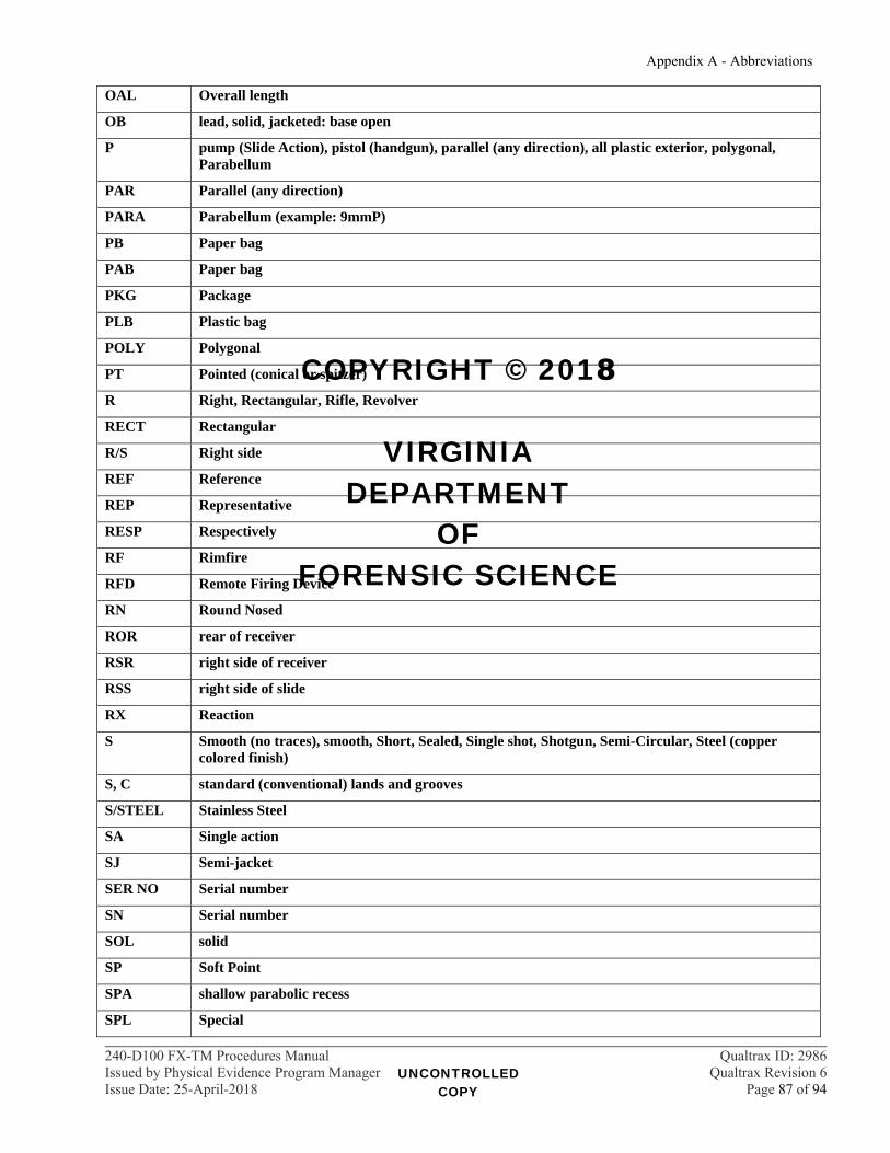
Appendix A - Abbreviations
240-D100 FX-TM Procedures Manual Qualtrax ID: 2986Issued by Physical Evidence Program Manager Qualtrax Revision 6Issue Date: 25-April-2018 Page 87 of 94
OAL Overall length
OB lead, solid, jacketed: base open
P pump (Slide Action), pistol (handgun), parallel (any direction), all plastic exterior, polygonal, Parabellum
PAR Parallel (any direction)
PARA Parabellum (example: 9mmP)
PB Paper bag
PAB Paper bag
PKG Package
PLB Plastic bag
POLY Polygonal
PT Pointed (conical or spitzer)
R Right, Rectangular, Rifle, Revolver
RECT Rectangular
R/S Right side
REF Reference
REP Representative
RESP Respectively
RF Rimfire
RFD Remote Firing Device
RN Round Nosed
ROR rear of receiver
RSR right side of receiver
RSS right side of slide
RX Reaction
S Smooth (no traces), smooth, Short, Sealed, Single shot, Shotgun, Semi-Circular, Steel (copper colored finish)
S, C standard (conventional) lands and grooves
S/STEEL Stainless Steel
SA Single action
SJ Semi-jacket
SER NO Serial number
SN Serial number
SOL solid
SP Soft Point
SPA shallow parabolic recess
SPL Special
UNCONTROLLED COPY
COPYRIGHT © 2018
VIRGINIA DEPARTMENT
OF FORENSIC SCIENCE
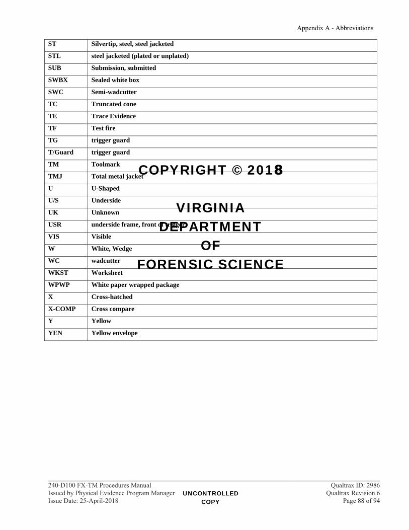
Appendix A - Abbreviations
240-D100 FX-TM Procedures Manual Qualtrax ID: 2986Issued by Physical Evidence Program Manager Qualtrax Revision 6Issue Date: 25-April-2018 Page 88 of 94
ST Silvertip, steel, steel jacketed
STL steel jacketed (plated or unplated)
SUB Submission, submitted
SWBX Sealed white box
SWC Semi-wadcutter
TC Truncated cone
TE Trace Evidence
TF Test fire
TG trigger guard
T/Guard trigger guard
TM Toolmark
TMJ Total metal jacket
U U-Shaped
U/S Underside
UK Unknown
USR underside frame, front of trigger
VIS Visible
W White, Wedge
WC wadcutter
WKST Worksheet
WPWP White paper wrapped package
X Cross-hatched
X-COMP Cross compare
Y Yellow
YEN Yellow envelope
UNCONTROLLED COPY
COPYRIGHT © 2018
VIRGINIA DEPARTMENT
OF FORENSIC SCIENCE
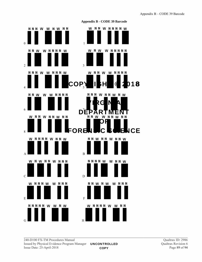
Appendix B – CODE 39 Barcode
240-D100 FX-TM Procedures Manual Qualtrax ID: 2986Issued by Physical Evidence Program Manager Qualtrax Revision 6Issue Date: 25-April-2018 Page 89 of 94
Appendix B - CODE 39 Barcode
0 1
2 3
4 5
6 7
8 9
A B
C D
E F
G H
UNCONTROLLED COPY
COPYRIGHT © 2018
VIRGINIA DEPARTMENT
OF FORENSIC SCIENCE

Appendix B – CODE 39 Barcode
240-D100 FX-TM Procedures Manual Qualtrax ID: 2986Issued by Physical Evidence Program Manager Qualtrax Revision 6Issue Date: 25-April-2018 Page 90 of 94
I J
K L
M N
O P
Q R
S T
U V
W X
Y Z
Space $
UNCONTROLLED COPY
COPYRIGHT © 2018
VIRGINIA DEPARTMENT
OF FORENSIC SCIENCE

Appendix B – CODE 39 Barcode
240-D100 FX-TM Procedures Manual Qualtrax ID: 2986Issued by Physical Evidence Program Manager Qualtrax Revision 6Issue Date: 25-April-2018 Page 91 of 94
/ +
% -
. *
UNCONTROLLED COPY
COPYRIGHT © 2018
VIRGINIA DEPARTMENT
OF FORENSIC SCIENCE

Appendix C – Reagents
240-D100 FX-TM Procedures Manual Qualtrax ID: 2986Issued by Physical Evidence Program Manager Qualtrax Revision 6Issue Date: 25-April-2018 Page 92 of 94
Appendix C – Reagents Distance Determination
Sodium Rhodizonate Saturated Solution
Prepared fresh for each usage Add Sodium Rhodizonate to reverse osmosis (R/O) or deionized (DI) water until the solution is a dark
orange/tea color
5% Hydrochloric Acid Solution
Add 5 milliliters of concentrated Hydrochloric Acid to 95 milliliters of R/O or DI water
Buffer Solution
Dissolve 1.9 grams of Sodium Bitartrate and 1.5 grams of Tartaric Acid in 100 milliliters of R/O or DI water
15% Acetic Acid Solution
Add 150 milliliters of Glacial Acetic Acid to 850 milliliters of R/O or DI water
5% Acetic Acid Solution
Add 50 milliliters of Glacial Acetic Acid to 950 milliliters of R/O or DI water.
Dithiooxamide (DTO) Solution
Prepare fresh for each usage Dissolve 0.2 grams of DTO in 100 milliliters of ethanol
Ammonium Solution
Combine 20 milliliters of ammonium hydroxide with 50 milliliters of R/O or DI water
Sensitized Blank for Modified Griess Test
Solution 1: Add 0.75 grams of Sulfanilic Acid to 150 milliliters of R/O or DI water and mix Solution 2: Add 0.42 grams of Alpha Naphthol to 150 milliliters of methanol and mix Mix equal volumes of solution 1 and 2 in a clean photo tray. Saturate pieces of filter paper or desensitized photo paper in this solution and air dry Store dried sensitized blanks in an airtight plastic container
Nitrite Test Strips or Cotton Swabs
Dissolve 0.6 grams of Sodium Nitrite in 100 milliliters of R/O or DI water Saturate pieces of filter paper or cotton swabs in this mixture Store dried strips or swabs in an airtight plastic container
Diphenylamine
Dissolve 0.3 grams of diphenylamine in 20 milliliters of concentrated sulfuric acid Pour mixture into 10 milliliters of glacial acetic acid
UNCONTROLLED COPY
COPYRIGHT © 2018
VIRGINIA DEPARTMENT
OF FORENSIC SCIENCE
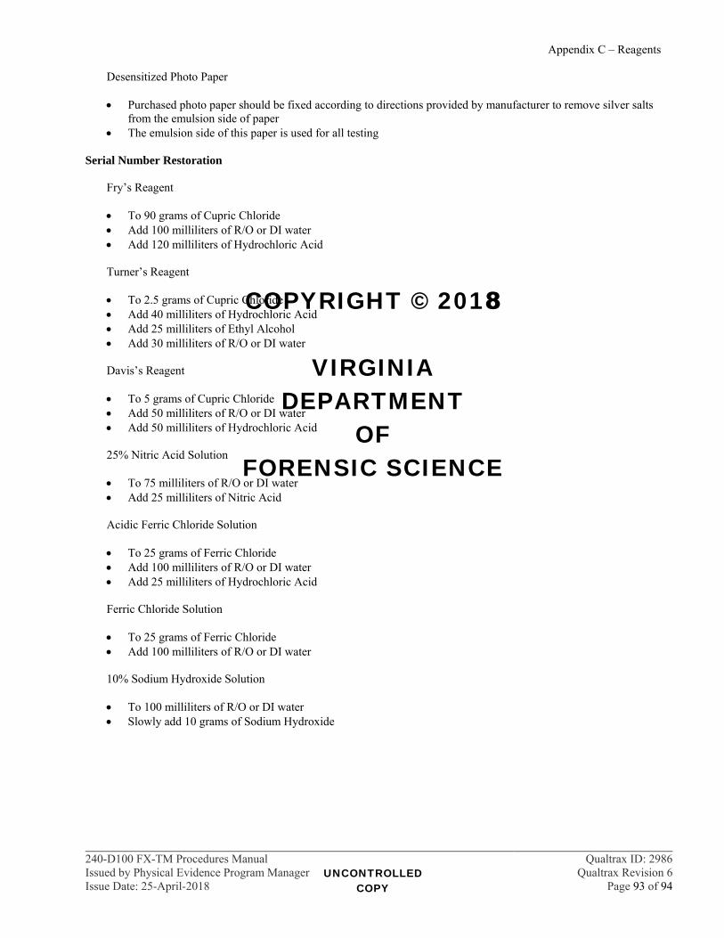
Appendix C – Reagents
240-D100 FX-TM Procedures Manual Qualtrax ID: 2986Issued by Physical Evidence Program Manager Qualtrax Revision 6Issue Date: 25-April-2018 Page 93 of 94
Desensitized Photo Paper
Purchased photo paper should be fixed according to directions provided by manufacturer to remove silver salts from the emulsion side of paper
The emulsion side of this paper is used for all testing Serial Number Restoration
Fry’s Reagent
To 90 grams of Cupric Chloride Add 100 milliliters of R/O or DI water Add 120 milliliters of Hydrochloric Acid
Turner’s Reagent
To 2.5 grams of Cupric Chloride Add 40 milliliters of Hydrochloric Acid Add 25 milliliters of Ethyl Alcohol Add 30 milliliters of R/O or DI water
Davis’s Reagent
To 5 grams of Cupric Chloride Add 50 milliliters of R/O or DI water Add 50 milliliters of Hydrochloric Acid
25% Nitric Acid Solution
To 75 milliliters of R/O or DI water Add 25 milliliters of Nitric Acid
Acidic Ferric Chloride Solution
To 25 grams of Ferric Chloride Add 100 milliliters of R/O or DI water Add 25 milliliters of Hydrochloric Acid
Ferric Chloride Solution
To 25 grams of Ferric Chloride Add 100 milliliters of R/O or DI water
10% Sodium Hydroxide Solution
To 100 milliliters of R/O or DI water Slowly add 10 grams of Sodium Hydroxide
UNCONTROLLED COPY
COPYRIGHT © 2018
VIRGINIA DEPARTMENT
OF FORENSIC SCIENCE

Appendix C – Reagents
240-D100 FX-TM Procedures Manual Qualtrax ID: 2986Issued by Physical Evidence Program Manager Qualtrax Revision 6Issue Date: 25-April-2018 Page 94 of 94
Hydrofluoric Acid Solution
WARNING! Concentrated Hydrofluoric Acid is a “particularly hazardous substance”
and must be handled using appropriate PPE (laboratory coat, thick “rubber” gloves, and face shield). Calcium gluconate gel must be available in the work area.
Hydrofluoric Acid, either concentrated or the working solution, may not be handled when working alone.
To two (2) parts of Concentrated Hydrofluoric Acid Add one (1) part of Nitric Acid Add three (3) parts of Glycerol
Aqua Regia Solution
To 75 milliliters of Hydrochloric Acid Add 25 milliliters of Nitric Acid Do not store for future use
Cupric Chloride in Nitric Acid Solution
To five (5) grams of Cupric Chloride Add 100 milliliters of R/O or DI water Add three (3) milliliters of Nitric Acid
Zinc Alloy Etching Solutions
Solution 1 - To two (2) milliliters of Nitric Acid, add 98 milliliters of Phosphoric Acid Solution 2 - To 95 milliliters of R/O or DI water, add five (5) milliliters of Nitric Acid
Griffin’s Reagent
To 30 grams of Cupric Chloride Add 30 milliliters of R/O or DI water Add 30 milliliters of Hydrochloric Acid Add 120 milliliters of Methanol
UNCONTROLLED COPY
COPYRIGHT © 2018
VIRGINIA DEPARTMENT
OF FORENSIC SCIENCE