Department of Computer Science and Engineering - ethesis
33
[1] IDENTIFYING PERSISTENT FAULTS IN NETWORK ACCESS CONTROL SYSTEM GOVIND UPMAN (108CS054) SUNIL ORAM (108CS039) Department of Computer Science and Engineering National Institute of Technology Rourkela Rourkela–769008, Odisha, India 2012
Transcript of Department of Computer Science and Engineering - ethesis

[1]
IDENTIFYING PERSISTENT FAULTS IN
NETWORK ACCESS CONTROL SYSTEM
GOVIND UPMAN (108CS054)
SUNIL ORAM (108CS039)
Department of Computer Science and
Engineering
National Institute of Technology Rourkela
Rourkela–769008, Odisha, India
2012

[2]
IDENTIFYING PERSISTENT FAULTS IN
NETWORK ACCESS CONTROL SYSTEM
A Thesis submitted on
14th may, 2012
In partial fulfillment of the requirements for the degree of
Bachelor of Technology In
Computer Science and Engineering By
GOVIND UPMAN
(Roll 108CS054)
SUNIL ORAM
(Roll 108CS039)
Under the supervision of
Prof. P. M. Khilar & Prof. M. N. Sahoo
Department of Computer Science and Engineering
National Institute of Technology Rourkela
Rourkela -769 008, Odisha, India
[3]
National Institute Of Technology Rourkela
CERTIFICATE
This is to certify that the project entitled, “Identifying Persistent Faults In Network Access
Control System” submitted by Govind Upman (108CS054) and Sunil Oram (108CS039) is an
authentic work carried out by them under my supervision and guidance in partial fulfillment of
the requirements for the award of the degree of Bachelor of Technology in Computer Science
and Engineering at National Institute of Technology, Rourkela.
To the best of my knowledge, the matter embodied in the project has not been submitted to any
University / Institute for the award of any Degree or Diploma.
Prof. P. M. Khilar Prof. M. N. Sahoo (Dept. of Computer Science & Engineering (Dept. of Computer Science & Engineering
National Institute of Technology, National Institute of Technology,
Rourkela-769008) Rourkela-769008)
Date: Place: NIT, Rourkela

[4]
ACKNOWLEDGEMENT
We would like to express our profound gratitude and indebtedness to our guide Prof. P. M.
Khilar & Prof. M.N. Sahoo, Department of Computer Science and Engineering, NIT Rourkela
for intruding the present topic and for his inspiring intellectual guidance, constructive criticism
and valuable suggestion throughout the project work.
Finally we would like to thank to our parents and colleagues for their support and motivation to
complete this project.
Submitted by:
Sunil Oram Govind Upman
Roll No: 108CS039 Roll No: 108CS054
Computer Science and Engineering Computer Science and Engineering
National Institute of Technology National Institute of Technology
Rourkela- 769008 Rourkela - 769008

[5]
CONTENTS
Page No.
Certificate 3
Acknowledgement 4
Abstract 7
List of Figures 8
Chapter 1 INTRODUCTION 9
1.1 Introduction……...………………………………………………...10
1.2 Basic Concept...................................................................................11
1.2.1 Preadmission and post admission.......................11
1.2.2 Agent versus Agent less………..........................11
1.2.3 Out of band versus Inline……………….…...…11
1.2.4 Remediation, Quarantine ……...........................12
1.2.5 Captive Portals…………………………....……12
1.2.6 IEEE 802.1X....................................................13
1.3 Motivation and Objective…………………….……………….....…14
1.4 Thesis Organization…………………………………………….…..15
1.5 Summary……………………………………………………………15

[6]
Page No.
Chapter 2 BACKGROUND 16
2.1 Classification of Faults………………………………………….….17
2.1.1 Classic Faults………………………………….17
2.1.2 Generic NAC Faults..........................................18
2.2 Summary............................................................................................19
Chapter 3 ACCESS CONTROL LIST 20
3.1 Types of Access List………………………………………….…....21
3.2 Syntax of Access List………………………….………………..….22
3.3 Summary……………………………………………………………24
Chapter 4 PROPOSED WORK AND SIMULATION 25
4.1 Assumptions…………………………………………………..…….26
4.2 CISCO Packet Tracer……………………………………………….26
4.3 Simulation Parameters……………………………………….…......27
4.4 Examples showing implementation……………………………..….27
4.5 Summary…………………………………………………………....29
Chapter 5 RESULTS AND CONCLUSION 30
5.1 Simulation Results……………………………………….………....31
5.2 Conclusion and Future Work…………………….……..….……….32
REFERENCES 33
[7]
ABSTRACT
The task of configuring and managing security policies in enterprise networks is
becoming harder due to complex policy constraints of the organizations and rapid changes in the
network topologies. Typically, the organizational security policies are defined as a collection of
rules for allowing/denying service accesses among various network zones. Implementation of the
policy can be realized in a distributed fashion via implementation of appropriate sets of access
control rules (ACL) within the interface switches (Layer-3 routers) of the network. Due to
organizational complex security needs the verification of the ACL implementations with respect
to the security policy is a major technical challenge to the network administrators. The problem’s
complexity increases with changes in network topologies. In any point of time, the failure within
the network infrastructure may occur, causing invalidation and performance degradation of the
network parameters. Hence, the existing security implementation (distribution of ACL rules)
may not conform to the policy.
Here we address the problem by analysing Network Access Control model with ACL
implementation in a static fault environment considering static and persistent faults in network
access control. We have considered various network topologies for our study and the simulation
has been run for networks comprising of number of nodes from 8 to 256. Then we have induced
faults to these networks and tried to determine the average and maximum fault latency in these
networks in a simulation based approach.
[8]
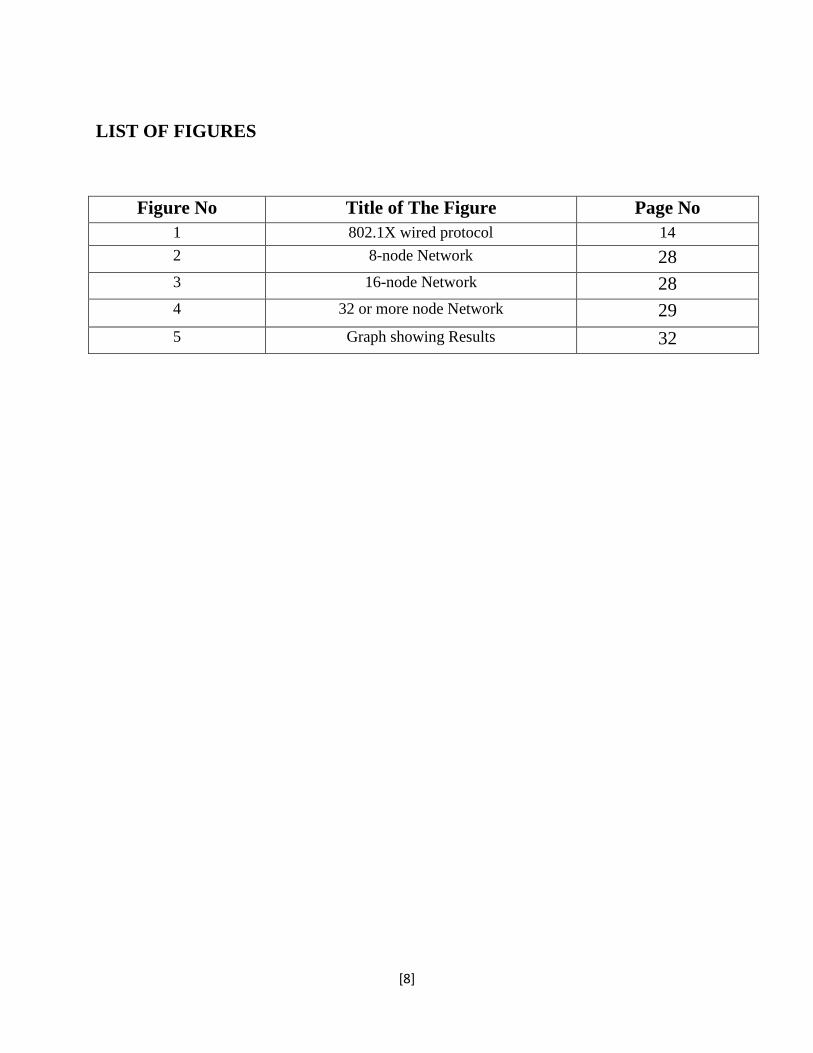
LIST OF FIGURES
Figure No Title of The Figure Page No
1 802.1X wired protocol 14
2 8-node Network 28
3 16-node Network 28
4 32 or more node Network 29
5 Graph showing Results 32

[9]
Chapter1
INTRODUCTION
[10]
1.1 INTRODUCTION
Over recent years the increase in the number of mobile workers, the number and
types of mobile devices, and in the number of non-employees requiring access to
corporate networks has dissolved the network perimeter. Access requests can come from
anyone and anywhere, which is why organizations are turning to network access control
(NAC) technologies.
Generic network access control at its core is a simple concept: Your identity
should govern what you are allowed to do over the network. NAC, thus, is simply the
hardware and software that as a whole lets you enforce access control policies based on
your identity. NAC uses the set of protocols in order to implement policies that describe
the security of network by defining sets of policies when end system attempts to access
the network. NAC might also combine the automatic remediation process with the
network system. It allows the routers, the switches and the firewalls to work together with
back-office servers.
When all of the parts are in place, NAC acts like a way to apply a policy for
accessing network across LAN, wireless and VPN infrastructures. The access control
policy in NAC might range from simple, such as a go or no-go decision on network-
access or a choice of virtual LANs, or it can be as complex as a set of per-user firewall
rules defining which parts of network are accessible.
Since NAC is a huge step for people to consider adding to their network, all kinds
of slants are seen on the idea of NAC. For example, some products tightly focus on
endpoint security considering it to be the key reason for implementing NAC, while others
concentrate on authentication and policy as the prime virtues. In reality, a good NAC
product is not just a way to swing users between quarantine and production Virtual-
LANs, but a generic access-control system that authenticates and authorizes all traffic the
traffic it encounters. NAC is a bit different from control systems such as a firewall,
because NAC provides us the tools available to provide user-focused access control.

[11]
When an end system connects to a computer network, it is not allowed to accesses
anything unless it complies with different defined policy, including system update level,
antivirus protection level and configuration. End system is checked by preinstalled
software agent. When the policy is met, the computer is able to access the network
resources and the internet, within the policy defined inside the NAC system. NAC is
mainly used for the end point health check .Access to the network is given to the end user
according to the profile and health check of the person.
We know that fault detection is the first phase of fault management, where
unexpected error may occur and should be properly identified by the network system.
This chapter is organized as follows. In section 1.1, we introduced the network access
control system. The basic concepts are discussed in section 1.2. In section 1.3, the
motivation and objective of the thesis is mentioned. Thesis organization is presented in
section 1.4. This chapter is ended with summary in section 1.5.
1.2 BASIC CONCEPTS
1.2.1 Preadmission and Post admission
Basically in NAC there are two prevailing design philosophies, based on policies
enforced before or after the end-system gain access to the network. Pre-admission NAC,
end-system are inspected before being allowed in to the network. Alternatively Post-
admission NAC makes enforcement decisions based on user actions, after those users
have been connected to the network [9]
.
1.2.2 Agent versus agent less
The fundamental concept behind NAC is to allow the network to make access
control decisions based on the end system’s intelligence. It uses the agent or agent less
software to report end system characteristics depending upon whether it use scanning and
networking inventory techniques to discern those characteristics remotely.
[12]
1.2.3 Out of band versus inline
In out of band systems, agents are placed on the end systems and report
information to central console, which in turn control the switches to enforce policy.
Alternatively the inline solutions can be single box solutions which act as single firewalls
for access layer networks and enforce the policy. Out of band solutions have the
advantage of reusing the existing infrastructure but inline products can be easier to deploy
on new network, and may provide more network enforcement capabilities, because they
directly control the network packets on the wire.
1.2.4 Remediation, Quarantine
Network operators deploy NAC products and expect that some unsuccessful end user
will be denied access to the network. For this, NAC solutions need a mechanism to
remediate the end system problems that deny them access.
A quarantine network is a restricted IP network. It provides users with routed access
only to certain hosts and applications. Quarantine is implemented using concept of
VLAN. When NAC product finds that the end user is out of date. Their switch port is
assigned to a VLAN that is routed only to patch and update servers, not to the rest of the
network. Other solution use ARP, NDP for quarantine.
1.2.5 Captive Portals
A captive portal intercepts HTTP, redirecting users to a web application that provides
instructions and tools for updating their computer. This is similar to the way wireless
access works at the public access points.
[13]
External Captive Portals allow organizations offload wireless controllers and switches
from hosting web portals. Single Portals can be used for both wired and wireless
authentication.
1.2.6 IEEE 802.1X
IEEE 802.1X is an IEEE standard for port based authentication. It is a part of the IEEE
802.1 group of protocols. It provides authentication to the user wishing to connect to a
LAN or WLAN. It consists of group of protocols. IEEE 802.1X encapsulates Extensible
Authentication Protocol over IEEE 802 which is also known as EAP over LAN (EAPOL)
[9].
IEEE 802.1X provides port authorization on a per-user or per-host basis (the
authenticator will not forward frames until the RADIUS server signals that the supplicant
is authorized)
IEEE 802.1X provides the following core capabilities:
• Port authorisation on a per-user or per-host basis (the authenticator will not forward
frames until the RADIUS server signals that the supplicant is authorised)
• Support for multiple authentication methods (thanks to the use of EAP)
• Separation of the authenticator from the back-end authentication server, allowing user
management and policy decision making to be centralised.

[14]
802.1X WIRED PROTOCOLS
Fig1:802.1X wired protocols
[Source= http://en.wikipedia.org/wiki/File:802.1X_wired_protocols.png]
1.3 Motivation & Objective
Network Access Control has been extensively employed in large scale
organizations to define and implement policies that describe how to regulate access to
network nodes by the end users when they are initially attempting to access the network.
Motivated by the need of fault detection in the network access control and its analysis,
the following objective was undertaken in this project.

[15]
At the time of operation, network infrastructure may encounter a failure, thereby
invalidating the control policies and resulting in performance degradation of the
network parameters. Here we address the problem by analysing Network Access
Control model with ACL implementation in a static fault environment. In order to
validate the proposed schemes, we followed CISCO packet tracer.
1.4 Thesis Organization
In this thesis, we present the introduction, motivation and objective in chapter 1.
Chapter 2 discusses the necessary background of Network Access Control and possible
types of faults in a NAC system.
Chapter 3 puts light on Access-Control-Lists, their types and implementation steps
which are used in this project to incorporate Access-Control within a network.
Chapter 4 describes the details related to simulation carried out to identify the persistent
fault inside the NAC under static fault environment.
Chapter 5 shows the conclusion drawn from the various simulation and experimental
results and future scope for the research in the field of Network Access Control.
1.5 Summary
Here in this chapter we introduced the basic fundamentals of Network-Access-
Control and the terminology associated with it. We discussed IEEE 802.1X which is
the standard for port-based NAC. Then we came across the motivation and objective
behind this work, which was followed by a short description of how this thesis
progresses chapter-wise in thesis organization.

[16]
Chapter 2
BACKGROUND

[17]
2.1 Classification of Faults
Basically here we classified faults into two categories that are basic faults and
generic faults typical to NAC. In section 2.1.1 we focus on classic fault structure inside a
network and in section 2.1.2 we shall describe the common reasons for the occurrence of
these faults inside a network.
2.1.1 Basic faults
Basic faults are mainly divided into four types
Intermittent faults
Persistent faults
Transient faults
Byzantine faults
Intermittent faults-
Malfunctioning of a device or system that occurs at irregular interval of
times but functions normally at other times. Intermittent faults are common in
Computer software. It can be caused by several factors, from that some of
may be random, which occur simultaneously. A simple example error in
borderline electrical connection in the wiring or component of a circuit, where
two conductors may touch subject to a minor change in temperature,
vibration, orientation, voltage etc.
Persistent faults-
These are just like permanent faults which do not disappear when power is
disconnected. A simple example is faults in underground power cables. These
faults have to be corrected as soon as they occur. There can be various reasons
for these faults. Once they occur, persistent faults continue to keep the
network segment down unless corrected.
[18]
Transient faults-
Transient faults are faults that appear for a very small time. These are
temporary in nature. These can be caused by lightening, or voltage
fluctuations. These faults are non-persistent in nature and remain in the
network for a very small time. These types of faults are temporary in nature.
That is faults are no longer present if power is disconnected for a short time.
Faults in overhead power lines are transient in nature.
Byzantine faults-
Byzantine faults are faults that occur due to a combination of transient,
intermittent and persistent faults. Byzantine faults are hard to correct and have
the capacity to bring down a network segment as it includes persistent as well
as intermittent faults.
In this project, we considered only the persistent faults in network access
control of a large class network having a large number of components. This is due to
the fact that the network access control components are more likely to suffer from
persistent faults. For example, if we change the IP address of an end user machine of
NAC to another IP address of a different network, the end user machine cannot be
accessed showing a persistent fault. Until unless this fault is detected the appropriate IP
address cannot be assigned. Therefore, it is essential for every NAC system to detect
and diagnose the persistent faults in order to prevent the entire NAC system from
interrupted service to the end users.
2.1.2 Generic faults related to NAC
These are the generic faults that can occur inside any network and are generally the
reason behind most of networking related faults.

[19]
Node failure:
If a node goes down due to reasons such as power failure or a hardware
failure inside the device-
Link failure:
Link failure occurs when the connecting media becomes faulty and the
connection of the end-device is lost to the network.
Configuration Error:
Fault generated due to erroneous network configuration inside the
channelling device or end-device’s network adaptors.
Authentication generated errors:
Authentication related faults can arise out of an unintentional access
control policy in place within the network traffic controlling devices.
2.2 Summary
In this chapter we discussed the basic fault structure inside a network and generic
faults possible inside a NAC system that are capable of bringing the whole network
down. To ensure optimal operation of all the activities inside the network, these faults
must be diagnosed and eliminated from the network as early and as effectively as
possible.

[20]
CHAPTER 3
ACCESS CONTROL LISTS
[21]
3. ACCESS CONTROL LIST
Building and managing network system involves more than just packet transfer. We
also should consider that right people should able to access to the network. In short
we need to implement security, robustness and business policy with the network.
This is about network policies and how to implement those policies using CICSO
access lists. The access lists in this paper deal with only the IP protocol. Here all the
example CISCO access lists and many of the concepts are generic and applied to the
routers. ACLs cannot prevent all possible kinds of attacks on the network, but they
are good at filtering out a lot of the garbage and then letting another component
within the firewall system deal with the application layer attacks.
In this chapter Access-Control-Lists have been explained in detail. In section 3.1
we discuss categories of ACLs. In section 3.2 we discuss the syntax-structure of the
access control lists and the various terminologies associated with it.
3.1 Types of Access Lists
There are two basic types of access lists.
1. Standard Access lists: These lists are used to implement three types of policy
controls.
Accesses to router resources.
Route distribution
Packets passing through a router
The standard list of access list is used to build policy sets of either IP address
or Network number. Once policy sets are defined with the standard access
lists, the access list can restrict access to the network resources or internet,
determine which routes are accepted and distributed, and change routing
metrics to influence traffic behavior [2].
[22]
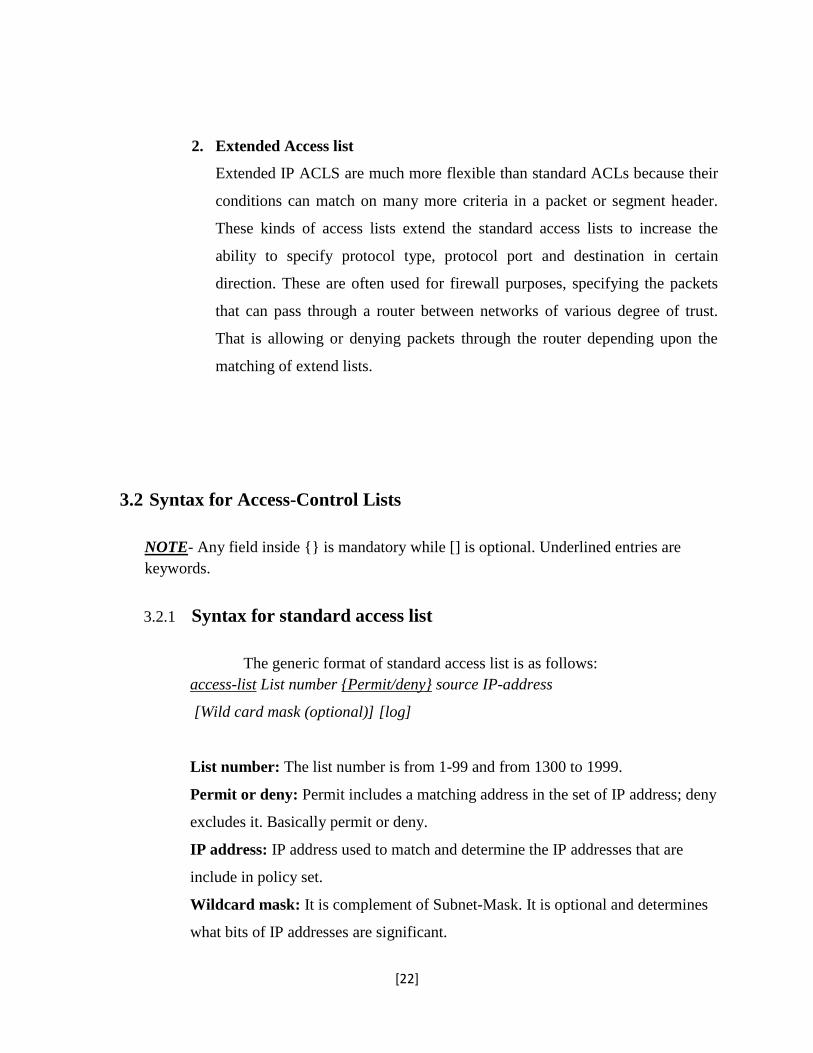
2. Extended Access list
Extended IP ACLS are much more flexible than standard ACLs because their
conditions can match on many more criteria in a packet or segment header.
These kinds of access lists extend the standard access lists to increase the
ability to specify protocol type, protocol port and destination in certain
direction. These are often used for firewall purposes, specifying the packets
that can pass through a router between networks of various degree of trust.
That is allowing or denying packets through the router depending upon the
matching of extend lists.
3.2 Syntax for Access-Control Lists
NOTE- Any field inside {} is mandatory while [] is optional. Underlined entries are
keywords.
3.2.1 Syntax for standard access list
The generic format of standard access list is as follows:
access-list List number {Permit/deny} source IP-address
[Wild card mask (optional)] [log]
List number: The list number is from 1-99 and from 1300 to 1999.
Permit or deny: Permit includes a matching address in the set of IP address; deny
excludes it. Basically permit or deny.
IP address: IP address used to match and determine the IP addresses that are
include in policy set.
Wildcard mask: It is complement of Subnet-Mask. It is optional and determines
what bits of IP addresses are significant.

[23]
3.2.2 Syntax for extended access list
The generic format of extended access list is followed-
access-list List-number {Permit/deny} Protocol source source-wildcard
[operator source-port] destination dest-wildcard [operator dest-port] [precedence
precedence-number] [tos tos] [established] [Log/log-input]
List number: Access list number from 100-199 and 2000-2699
Protocol: Defines the internet protocol for filtering. Available options are
keywords such as TCP or UDP, or the number of the protocol as seen in the IP-
header.
Source specification: A specification of the form [IP address] [Wildcard
mask] [Port number specification (only for UDP or TCP)].
Destination specification: A specification of the form [IP address] [Wildcard
mask] [Port number specification (only for UDP or TCP)].
Operator source-port: Defines the name or number of a source TCP or UDP
port. Operators are gt, lt, neq, eq, range etc.
Similarly for operator dest-port.
Tos tos-number: Used for filtering by the type of service level specified by a
name or number (0 through 7)
Logging: If the logging keyword is present, it turns on a log of all packets
information every time the access list is matched.

[24]
3.3 Summary
In this chapter Access-Control-Lists, which are implemented to incorporate
Access-Control policies into the network were described. We described the
common types of Access-Control lists i.e. standard and extended Access Lists. We
also had a look at their syntax-structure and the syntax structure to implement these
access control policies inside the network routers

[25]
Chapter 4
PROPOSED WORK AND
SIMULATIONS
[26]
4.1 ASSUMPTION
Because creating large scale networks is expensive and time-consuming, network routing
algorithms are evaluated using the simulation based approach.
Every node in network runs on separate thread. In real environment each node is machine
situated at different places. As we are simulating it in single system each node uses different port
address.
In this chapter’s section 4.1 we have described the assumptions that are conventionally
made while simulating the real life networks on a single machine using a proper simulator. In
section 4.2 we describe the CISCO proprietary Cisco Packet Tracer. This tool has been used in
our project work with the purpose of studying static fault environment inside a NAC system.
Section 4.3 lists down the required parameters for simulation. In section 4.4 we have included
some screenshots showing the types of networks topologies upon which simulation work has
been carried out.
4.2 Cisco Packet Tracer
Cisco Packet Tracer is a powerful network simulation program that allows the
implementers to experiment with network behaviour. As an integral part of the Networking
Academy comprehensive learning experience, Packet Tracer provides simulation,
visualization, authoring, assessment, and collaboration capabilities of complex technology
concepts.
The simulation-based environment helps users develop modern networking models.
Packet Tracer allows users to easily learn and demonstrate complex technical concepts and
networking systems design.

[27]
4.2.1 Supported Protocols
Packet Tracer supports various protocols belonging to various networking layers. Most
notable of them being FTP, SMTP, HTTP, DHCP, DNS, TCP, UDP, ICMP, IPv4, IPv6,
ARP, NAT, 802.3,802.11
4.3 SIMULATION PARAMETERS
Simulation is done using Packet Tracer, employing ICMP protocol (ping). The simulation
has been carried out for 8, 16, 32, 64, 128, and 256 nodes.
TTL (Time to Live): Lifetime of a packet before being discarded – 16.
Waiting time for each node is defined as maximum latency for previous transmission.
The packet tracer carries out the ICMP PING request to determine whether the network is
faulty or fault-free. To achieve this it carries out PING request through the shortest path
possible between the end nodes of the network.
4.4 Examples showing implementation
Fig. 4.1 Network topology used for a network with N=8

[28]
Fig 4.2 Network topology employed for N=16
Fig 4.3 Network topology employed for N >= 32

[29]
4.5 Summary
In this chapter we discussed the general assumptions that are made while carrying out
simulations in a virtual environment. Other than that we came to know about “CISCO packet
tracer” simulator software and the various protocols it supports. Specifying simulation
parameters helps us achieve the kind of output data we want to receive through the simulation
process. Several diagrams were shown to demonstrate the network topologies that were studied
and simulated in the project.

[30]
CHAPTER 5
RESULTS AND CONCLUSION
[31]
5.1 Simulation Results
In order to validate the proposed fault model such as persistent faults in NAC system, we
represented the entire NAC system by considering a general topology network. Usually the NAC
systems follow general network topology having a number of nodes as well as number of links.
To study the behavior of small to large NAC systems, starting from an 8 nodes NAC to 256
nodes NAC has been considered for all simulations.
After carrying out the simulations over each network topology, the ICMP Ping timings
were obtained if the network contained any faults. These simulations were repeated over another
network with different topology but same aggregate number of nodes. The results obtained were
noted down to calculate the maximum and average latency for a general network with given
number of nodes. The maximum and average latency refers to the maximum and average time
taken between fault detection and fault occurrence in the network access control of a network
respectively.
These values were later plotted versus number of nodes (N) in the network topology and
results are shown in the graph (Fig.5.1). As the number of nodes in NAC increases, the
maximum and average fault latency in the system increases proportionately.
Here in the section 5.1 we have discussed the results obtained and the trends observed
after the study followed by the simulation process with the help of a graph.
In section 5.2 we describe the conclusions derived from the project work along-with the
future scope of research in the area of Network Access Control.

[32]
Fig. 5.1 Maximum & Average Latency versus N
5.2 Conclusion and Future Work
The Packet Tracer propagates status information as quickly and through the best path
possible to allow it to be effectively handled and monitored under static faulty network
scenarios. The results obtained for an Access-Control implemented network were in accordance
with the standard network fault analysis model.
The work presented here can be further expanded in several areas particularly as a
dynamic fault based network access control analysis. It can also incorporate intermittent fault
analysis with a focus towards fault tolerance in the network provided.
Fault
Latency
No. of Nodes (N)
[33]
REFERENCES
[1] Cisco CTA.
http://www.Cisco.com/en/US/solutions/ns340/ns394/ns171/ns466/ns617/net_design_
guidance0900aecd80417226.pdf
[2] Cisco Switch Support for Cisco NAC Appliance.
http://www.Cisco.com/en/US/products/ps6128/products_device_support_table09186a
008075fff6.html#wp60598.
[3] Microsoft TechNet on Network Access Protection.
http://www.Microsoft.com/technet/network/nap/default.mspx
[4] Cisco News Room http://newsroom.Cisco.com/dlls/index.html
[5] Planete team: http://www.inrialpes.fr/planete Imad AAD: [email protected]
[6] IEEE 802.1X http://grouper.ieee.org/groups/802/1/pages/802.1x.html
[7] IEEE Computer Society, 802.1X - Port Based Network Access Control, 2001
[8] Cisco Systems, Network Admission Control:
http://www.cisco.com/en/US/netsol/ns466/networking_solutions_package.html
[9] http://www.ieee802.org/1/pages/802.1x-rev.html
[10] IEEE Computer Society, 802.1X - Port Based Network Access Control, 2001
[11] P.M.Khilar, and S.Mahapatra, “Distributed Diagnosis in Dynamic Fault
Environment for Not-Completely Connected Network”, IEEE Indicon 2006 Conference,
New Delhi, India, I I - 1 3 Dec. 2006