Department for International Development · Department for International Development ... Cupola,...
24
Transcript of Department for International Development · Department for International Development ... Cupola,...


Department for International Development
DFID is a department of the British Government responsible for Britain’s contribution towardsinternational efforts to eliminate poverty. DFID works in partnership with governments ofdeveloping countries for poverty alleviation and supports long term programs to help tacklethe underlying causes of poverty. DFID recognizes that the development of Micro, Small andMedium Enterprises (MSMEs) is key to creating jobs and income in India. DFID is supportingthe development of the MSME sector in India through the MSME Financing and Developmentproject (MSMEFDP).
MSME Financing and Development Project
SIDBI is implementing a multi agency / multi activity project (MSMEFDP) for MSMEs. WhileSIDBI has been assigned the responsibility of implementing the project, the Department ofFinancial Services, Ministry of Finance, Government of India is the nodal agency for the same.The World Bank, Department for International Development (DFID) UK, KfW Germany andGTZ Germany are the international partners in the project.
Winrock International India
WII is a not-for-profit organization registered under the Societies Registration Act. WII worksin four principal program areas – Energy & Environment, Natural Resources Management,Climate Change and Outreach. WII is affiliated to the US based Winrock International, a globalnot–for–profit organization. In all areas, WII works towards achieving its mission to “developand implement solutions that balance the need for food, income and environmental quality”.
Winrock International India has been accorded recognition as a Scientific and Industrial Re-search Organization (SIRO) by the Department of Scientific & Industrial Research (DSIR),Ministry of Science & Technology, Government of India, under the Scheme on Recognition ofScientific and Industrial Research Organizations (SIROs)-1988.
Published by: Winrock International India, 788, Udyog Vihar, Phase V, Gurgaon - 122 001, Haryana;Tel: +91-124-430 3868; Fax: +91-124-430 3862; Website: www.winrockindia.org
For further details contact:
Project Management Division, SIDBI, Videocon Tower, Ground Floor, E-1, Rani Jhansi Road,Jhandewalan Extension, New Delhi - 110055, Phone - 91-11-23682473-76
DisclaimerThis booklet is an initiative of Small Industries Development Bank of India (SIDBI) under the MSMEFinancing and Development Project and funded by Department for International Development (DFID),UK. The views expressed here are not necessarily those of DFID/SIDBI. While every effort has beenmade to avoid any mistakes or omissions, SIDBI would not be in any way liable to any person /institution by reason of any mistake/ omission in the publication. The graphs, tables and other analysesof data that are carried in various parts of this publication have been drawn from a variety of resources,both primary and secondary.

vt; ekFkqj]vt; ekFkqj]vt; ekFkqj]vt; ekFkqj]vt; ekFkqj] ih,p-Mhih,p-Mhih,p-Mhih,p-Mhih,p-Mh
egkfuns’kdegkfuns’kdegkfuns’kdegkfuns’kdegkfuns’kd
Ajay Mathur, Ph. DDirector General
The contribution of Micro, Small and Medium Enterprises (MSMEs) has been significant in India’seconomic development. Due to its contribution towards employment and balanced regionaldevelopment, it is imperative to take measures to strengthen this vital sector.
With increased competition and the ongoing economic slowdown, adopting innovative practiceswhich can manage the bottom line are a necessity for enhanced competitiveness and profitability.Energy efficiency enhancement is a powerful bottom line management intervention for the MSMEsector, as it reduces energy consumption while maintaining current levels of productivity andquality – in other words, producing the same goods or services while using less energy.
The Bureau of Energy Efficiency (BEE) has a number of programs to facilitate delivery mechanismsfor energy efficiency in all sectors in the country. In the MSME units, local service providers,technology vendors and banks collaborate in the implementation of energy efficiency interventionson a sustainable for-profit basis. To enable this business model, BEE and SIDBI have signed aMemorandum of Understanding to partner and create a shelf of energy efficiency projects for25 MSME clusters across India.
This booklet contains wide-ranging tips on housekeeping for energy saving practices, at theshop-floor level in the foundry sector. I am delighted by this practical knowledge product andcongratulate SIDBI on their continued and innovative efforts in disseminating knowledge in thisimportant area.
I am confident that these simple housekeeping measures, identified best practices, and costsaving tools will help in raising awareness, reducing energy bills, and minimizing waste and willgo a long way in contributing to increased competitiveness of the entire MSME sector.
(Ajay Mathur)
3
MESSAGE

Energy conservation measures in the foundry sector4
FOREWORD
The Micro, Small and Medium Enterprises (MSMEs) sector has, over theyears, emerged as an important vehicle for the economic growth of India.The sector’s contribution to the Indian economy has been immense,providing the second largest source of employment, 45% of the industrialmanufacturing output and 35% of the country’s exports. Through its sheersize and potential, MSMEs play a vital role towards coordinated balancedregional development and inclusive growth of the country. It is noteworthythat this sector has also proved to be innovative, adaptable and resilient throughout differentphases of economic cycles.
Small Industries Development Bank of India (SIDBI), being the principal financial institution forMSMEs, is committed towards holistic growth of the MSME sector by making it strong, vibrantand globally competitive. We recognize energy efficiency as an effective tool to promotecompetitiveness of the MSME sector. SIDBI and the Bureau of Energy Efficiency (BEE) arecooperating to promote energy efficiency in MSME clusters. SIDBI has also tied up a line of creditwith the Japan International Cooperation Agency (JICA) to finance energy saving projects atconcessional terms.
In our endeavor towards creating widespread awareness on the necessity and urgency of energysaving measures in the MSME sector, we are bringing out this booklet which is an attempt todisseminate information on simple, cost-effective solutions in foundry enterprises. The bookletpresents measures that guide adoption of energy efficiency and greener practices to help MSMEscut costs and attain higher competitiveness. This publication is the second in the series; the firstbeing energy saving measures in the fruit and vegetable processing sector published in associationwith The Energy and Resources Institute (TERI).
I am confident that this booklet will be a valuable resource for MSMEs in the foundry sector inreshaping their manufacturing process by adopting energy efficiency measures and technologies.
I wish the entire MSME fraternity the very best for success in all their endeavors.
RM Malla,Chairman and Managing Director,SIDBI
FOREWORD

Energy conservation measures in the foundry sector 5
IntroductionThe Indian foundry industry is the fifth larg-
est in the world. There are more than 6,000foundries in India, and they have a combinedinstalled capacity of approximately 7.5 metrictonnes per annum (MTPA). Most foundries(nearly 95%) in India fall under the small andmedium scale category and are located in clus-ters. These units produce a wide range of cast-ings that include automobile parts, agriculturalimplements, machine tools, diesel engine com-ponents, manhole covers, sewing machinestands, pump-sets, decorative gates and valves.
Foundry Cluster Approx No. State Major Products
of Units
Batala 200 Punjab Agricultural implements, machine toolsBelgaum 100 Karnataka Automotive/oil engines, Electric motorsCoimbatore 500 Tamil Nadu Pumps/valves, Textile machine partsHowrah 300 West Bengal Machine covers, Sanitary pipesJalandhar 80 Punjab Agricultural implements, machine toolsKohlapur 250 Maharashtra Automotive/oil engines, Sugar mill partsLudhiana 350 Punjab Sewing machine parts, Auto partsRajkot 500 Gujarat Oil engine, Textile machine parts, Pump/valves
Many of the foundry clusters cater to somespecific markets. For example, the Coimbatorecluster is famous for pump-set castings, theKolhapur and the Belgaum clusters for automo-tive castings, and the Rajkot cluster for dieselengine castings. The major foundry clusters andtheir products are listed in Table 1.
Table 1: Details of major foundry clusters with major products in India
Manufacturing ProcessThe manufacturing process in a typical
foundry unit comprises many operations likesand preparation for moulds and cores, mouldand core preparation, charge preparation for themelting furnace, melting and pouring and arange of cleaning and machining operations.The process flow diagram for a typical foundryis shown in Figure 1.

Energy conservation measures in the foundry sector6
Energy Savings in CupolasCupola, which is the most commonly used
melting furnace in the Indian foundries is alsothe most energy intensive operation. It accountsfor up to 50% of a foundry’s total energy con-sumption and is a prime candidate to focus at-tention on, for improving energy use efficiencyin a foundry.
For efficient cupola operation, the followingoperating practices are recommended. For easycomprehension, the recommendations are cat-egorized under various operations, starting frompreparation of the cupola to tapping of moltenmetal.
Bottom SandThe base of the cupola plays an important
role in proper cupola functioning and in the flow
of hot metal from the cupola. Note the follow-ing points while making up the base of the cu-pola
Ensure that the bottom sand is free from iron,etc., and that it has the proper moisture andclay content.It should be dense, with a correctly rammedbottom, heeled up around the wall and slop-ing towards the tap hole.
Preparation of coke bedThe most important part in the successful op-
eration of a cupola is the preparation of the cokebed. The initial height of the bed above thetuyeres and the degree to which it is burned be-fore the charging commences are vital factorsgoverning, to a large extent, the metal tempera-ture and melting rates obtained during the early
Figure 1: Flowchart for a typical foundry
Energy conservation measures in the foundry sector 7
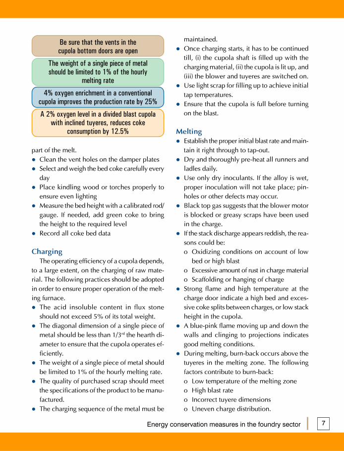
part of the melt.Clean the vent holes on the damper platesSelect and weigh the bed coke carefully everydayPlace kindling wood or torches properly toensure even lightingMeasure the bed height with a calibrated rod/gauge. If needed, add green coke to bringthe height to the required levelRecord all coke bed data
ChargingThe operating efficiency of a cupola depends,
to a large extent, on the charging of raw mate-rial. The following practices should be adoptedin order to ensure proper operation of the melt-ing furnace.
The acid insoluble content in flux stoneshould not exceed 5% of its total weight.The diagonal dimension of a single piece ofmetal should be less than 1/3rd the hearth di-ameter to ensure that the cupola operates ef-ficiently.The weight of a single piece of metal shouldbe limited to 1% of the hourly melting rate.The quality of purchased scrap should meetthe specifications of the product to be manu-factured.The charging sequence of the metal must be
maintained.Once charging starts, it has to be continuedtill, (i) the cupola shaft is filled up with thecharging material, (ii) the cupola is lit up, and(iii) the blower and tuyeres are switched on.Use light scrap for filling up to achieve initialtap temperatures.Ensure that the cupola is full before turningon the blast.
MeltingEstablish the proper initial blast rate and main-tain it right through to tap-out.Dry and thoroughly pre-heat all runners andladles daily.Use only dry inoculants. If the alloy is wet,proper inoculation will not take place; pin-holes or other defects may occur.Black top gas suggests that the blower motoris blocked or greasy scraps have been usedin the charge.If the stack discharge appears reddish, the rea-sons could be:o Oxidizing conditions on account of low
bed or high blasto Excessive amount of rust in charge materialo Scaffolding or hanging of chargeStrong flame and high temperature at thecharge door indicate a high bed and exces-sive coke splits between charges, or low stackheight in the cupola.A blue-pink flame moving up and down thewalls and clinging to projections indicatesgood melting conditions.During melting, burn-back occurs above thetuyeres in the melting zone. The followingfactors contribute to burn-back:o Low temperature of the melting zoneo High blast rateo Incorrect tuyere dimensionso Uneven charge distribution.
Be sure that the vents in thecupola bottom doors are open
The weight of a single piece of metalshould be limited to 1% of the hourly
melting rate
4% oxygen enrichment in a conventionalcupola improves the production rate by 25%
A 2% oxygen level in a divided blast cupolawith inclined tuyeres, reduces coke
consumption by 12.5%

Energy conservation measures in the foundry sector8
Tapping and SlaggingSlag is removed from the hot metal with the
help of a slag overflow notch. Normal slag iscolored grey to grey-green. The color and otherproperties of slag appearance can point to prob-lems in the cupola’s performance. Check for thefollowing:
Thick, viscous slag indicates insufficient fluxor low temperatures.Dark to black slag indicates a low bed (slagsometimes foamy) and oxidizing conditions.Light green to cream color slag indicates ex-cess flux.
Energy Saving Measures in a CupolaFurnace
Maintain a continuous melting operation.Long standby time increases energy lossesand causes metallurgical variat ions.Consider changing the cupola lining’s in-side diameter and tuyere’s diameter if ex-tended levels of low or high melt rates areexpected.Keep the upper stack full. Maximum chargelevels increase preheating of metals and re-duce coke consumption. Varying stack lev-els also cause metallurgical variations. Thus,maintaining constant stack levels decreasesmetallurgical variations.
With advances in melting practices, the con-ventional cupola has given way to theimproved and more efficient DividedBlast Cupola (DBC). Table 2 presents theadvantages of a DBC over conventionalcupolas.Another advanced technology used in cupolaoperation is oxygen enrichment of thecupola. The enrichment quantity usuallyrequired is around 2-4% of the air blast. Thefollowing advantages are achieved over theconventional cupola operation.o Carbon pick-up is highero Molten metal temperatures are higher by
about 300C
The measures for operating the cupola in themost efficient manner are given in Table 3.
Saving in Coke 7 - 10%Saving in Refractories 20%Si and Mn loss 5% as compared to 15%
in a conventional cupolaCarbon gain 20% better than con-
ventional cupola.Rise in metaltemperature 300CReduction inpollution 30%Cupola operation Operator friendly with
no pocking of tuyeresInclined tuyeres Inclined at 7.5 deg
downwards to yield bet-ter performance in thecombustion of coke.
Table 2: Advantage of DBC over conventionalCupola

Energy conservation measures in the foundry sector 9
Energy Savings in InductionFurnaces
Induction melting furnaces are inherentlymore efficient than cupolas. They are also easierto use because there are fewer steps in their op-eration and maintenance compared to cupolas.Further, most of the operating parameters in aninduction furnace are electrically controlled andspecifications are pre set as per the manufacturer’sguidelines. Hence, the only factor that needs tobe controlled in order to save energy during in-duction melting is cycle time. Adopting the fol-lowing practices will optimize the cycle time andallow efficient operation of the induction furnace.
Plan the charge mix and material beforehand.Weigh and keep the charge and alloying ele-ments ready before charging.Keep the size of the charge materials about1/3rd of the crucible’s diameter.First charge the steel and carburizers.Always keep the crucible full of charge andkeep poking in order to achieve maximum
compaction.Always operate the furnace at full power.Use proper frequency in the induction furnacefor various alloys, to ensure a faster mixing ofadditives and to reduce the cycle time.Cover the crucible with an asbestos blanketafter charging.Do not superheat the metal beyond the re-quired temperature.Avoid holding of molten metal.Avoid delay in the de-slagging operation.Keep the charge free from dirt and rust.Foundry return should be, preferably, shotblasted.
Dos Don’ts
Ensure that the bottom sand is free from Don’t hold the molten charge inside theiron, etc., and that it has the proper cupola. It consumes energy as well asmoisture and clay content. changes the metallurgical properties of
different batches.Measure the bed coke height with a Once charging starts, do not stop till, (i) thecalibrated gauge. If needed, add green cupola shaft is filled with the chargingcoke to bring the height to the required material, (ii) the cupola is lit up, andlevel. (iii) the blower and tuyeres are switched on.While charging, ensure that the diagonal Don’t use wet inoculants.dimension of a single piece of metal isless than 1/3rd the hearth diameter.Use light section scrap for filling up, to Don’t allow very heavy raw material piecesincrease the initial tap temperatures. weighing more than 1% of the hourlyDry and thoroughly pre-heat all runners melting rate, in the cupola.and ladles daily.
Table 3: Summary of operating tips in a Cupola
Weigh and keep the charge and alloyingelements ready before charging.
Keep the size of the charge materials about1/3rd of the crucible’s diameter.
Cover the crucible with an asbestos blanketafter charging.

Energy conservation measures in the foundry sector10
Dos Don’ts
Keep the size of charging material to about Don’t superheat the metal.one third of the furnace crucible size.Operate the furnace at full power and full Don’t hold the material in the furnace. Itcapacity. Go for maximum compaction of consumes power without increase inmaterial while charging. production.Keep the cycle time as short as possible by Don’t uncover the furnace unnecessarily.proper housekeeping.
Table 4: Summary of operating tips in Induction melting furnace
Table 4 summarizes the methods to be adoptedfor the efficient operation of the induction fur-nace.
Energy Savings in the Mouldand Core-Making Process andHeat Treatment
Making moulds and cores is another impor-tant operation in any foundry. Mould and coremaking and heat treatment together account for25–27% of the total energy consumed in afoundry. Given below is a list of operating prac-tices that must be followed to improve the effi-ciency of these processes.
Remove any metal pieces from the sand us-ing sand processing equipment so that no un-desirable object appears in the mould. Mal-function of even a single mould can lead tothe loss of material and energy.Ensure that components of the mould/coresuch as sand additives meet rated specifica-tions. Any deviation from the rated composi-tion may lead to frequent failure of moulds/cores. This could mean rejection of the en-tire lot of castings.The water content in the mould plays an im-portant role in binding of material. Too muchwater gives way to casting defects, while toolittle water may result in insufficient binding
and the collapse of the mould at critical points.For heat treatment furnaces with larger ca-pacities and voluminous heating chambers,always install more burners with smaller fir-ing capacities in place of a few burners withlarger firing capacity.Clean burner nozzles once in a month.Do proper planning to avoid furnace coldstarts.Don’t leave air supply open while fuel sup-ply is closed.Use temperature indicators and automatic con-trollers in place of human judgement. This willreduce the chances of overheating of the ma-terial and the resulting energy/material loss.Do not obstruct the flow of hot gases, theflame path and the exhaust port. Ensure thisby placing/arranging the material correctlyand through optimal loading of the furnace.
Don’t cut air supply while fuelsupply is running.
Every 200C rise in combustion air temperaturewill raise the thermal efficiency of the
furnace by 1%
Install more burners with smaller firingcapacities in place of a few burners with larger
firing capacity.

Energy conservation measures in the foundry sector 11
Dos Don’ts
Clean burner nozzles once in a month. Don’t obstruct the flow of hot gases, theUse optimum quantity of water while flame path and the exhaust port. Ensure thismould making. by placing/arranging the material correctlyEnsure proper planning to avoid furnace and through optimal loading of the furnace.cold start Don’t rely on human judgement forSeal unnecessary furnace openings and critical furnace parameters like temperature.leakages. Use digital temperature indicators.
Table 5: Summary of operating tips in core-making and heat treatment furnaces
Given in Table 5 are operating tips forimproving the efficiency of core-making heattreatment furnaces.
Energy Savings in theMachine Shop
For efficient operation, carry out routine andsimple maintenance of machine tools. This willhelp avoid expensive breakdown maintenance,which also leads to loss of production and otherassociated losses. Such routine maintenancetakes only a few minutes to complete and shouldbe conducted before the shift begins. The fol-lowing checks should be carried out in the rou-tine maintenance of machine tools:
Clean chips from the chip pan.Check hydraulic oil level in the main hydrau-lic tank and top up if required.Check the coolant levels in the coolant sumpand top up, if required.
Perform alignment check between spindle,carriage assembly and other components toensure accuracy of cut.Undertake periodic calibration of gauges andinstruments.
Energy Savings in theCompressed Air System
Air compressors are used in the machine shopfor pneumatic equipment and machine tools.Air compression consumes a lot of energy. FromFigure 2 it is clear that only 10 – 30% of inputenergy to the compressor reaches the point ofend-use and the balance 90 – 70% of the inputenergy is wasted in the form of friction and heatloss.
Figure 2: Sanky diagram of a compressed airsystem
Check the lubricating oil level in the guideways, lubricating oil tank and top up if required.
Perform alignment check between spindle,carriage assembly and other components to
ensure accuracy of cut.
Undertake periodic calibration of gaugesand instruments
Approximately10% gets to the
point of use!
Simple, cost effective measures give30% savings in generation,
transmission, distribution andavoiding misuse of compressed air
Deliveredcompressed
air
Elec
trici
ty c
onsu
med
by
com
pres
sor
Heat Loss

Energy conservation measures in the foundry sector12
Energy savings of up to 30% can be real-ized in a compressed air system by regularsimple maintenance measures. Some prac-tices that will optimize air compression arelisted below.
The location of air compressors and the qual-ity of air drawn by the compressors will havea significant influence on the amount of en-ergy consumed. The following points shouldbe taken into consideration while decidingthe location of compressors or combinedcompressed air systems.o Locate the compressor away from heat
sources such as kilns, dryers and otheritems of equipment that radiate heat.
The following Table 6 shows the relative powersavings that result from a decrease in intake airtemperature.
o The compressor should be placed wherethere is no particulate matter. Do not placethe compressor near spray coating booths,sawing machines, the buffing section, etc.
Any moisture in the inlet air to the compres-sor will affect its performance adversely. Thecompressor should be placed away fromequipment which may add moisture to theatmosphere, for example, rinsing lines, cool-ing towers, dryer exhaust, etc. If the com-pressed air is moist the components of thecompressed air system will corrode. Also, thespecific power consumption will increase.Choose the pressure setting in the compressedair system very carefully. Judge/assess the re-quirement of different compressed air usersbefore connecting them to common com-pressed air grid. This is the most importantcriterion for optimizing the efficiency of thecompressed air system.Segregate users of compressed air on the ba-sis of the pressure they require for proper op-eration. Set up two or more compressed airgrids if needed, with each having the air pres-sure set according to the requirement ofequipment in that particular grid. A singlecompressed air network will always havedelivery pressure set equal to the requirementof the equipment which demands the high-est pressure. This is not desirable.Some items of equipment in the grid requireair at low pressures. Do not use valves to re-duce the pressure in the compressed air grid,because it wastes the energy that is consumedin building up the excess pressure. Com-pressed air pressure must be set at the pointof generation.Optimization of compressor loading and un-loading pressure, and segregation of high andlow pressure loads in the compressed air gridcan lead to significant energy savings with-
Inlet temperature Relative air Power(0C) delivery (%) Saved (%)
10.0 102.0 +1.415.5 100 Nil21.1 98.1 -1.326.6 96.3 -2.532.2 94.1 -4.037.7 92.8 -5.043.3 91.2 -5.8
Table 6: Effect of inlet air temperature onenergy consumption
o The compressor should be located suchthat it draws cool ambient air from out-side because the temperature of the airinside the compressor room is high.While extending the air intake from theoutside of the building, minimize excesspressure drop in the suction line by se-lecting a duct of large diameter with thesmallest number of bends.

Energy conservation measures in the foundry sector 13
Every 40C rise in the inlet air temperatureresults in an increase in energy consumption
by 1%, to achieve an equivalent output.
Increase in air discharge pressure by1 kg/cm2 above the desired value will resultin an increase in the requirement of input
power by about 4–5%.
Higher the compressed air pressure, the moreexpensive it is to provide the air.
In industrial practice the typical acceptablepressure drop is 0.3 bar in the mains header
at the farthest point, and 0.5 bar in thedistribution system.
Clean the air intake filters regularly so thatclean air can enter the compressor and per-mit a low pressure drop across the filters.It has been observed that Free Air Discharge(FAD) by compressors increases by as muchas 12.5% in some cases by simply cleaningthe air intake filters.Maintain the proper level of tension in thebelt in compressors connected by belt drives.Improper belt tension, loose or vibrating beltscan cause an increase in power consump-tion of the prime mover by as much as 6%.Put the right kind of compressor to use. Thisis specially important in a compressed airnetwork consisting of several compressors ofthe same or different size, capacity, opera-tional efficiency, etc. The following pointsshould be noted while deciding the operat-ing pattern of compressorso If all compressors are similar, adjust the
pressure setting of the compressors so thatonly one compressor handles the loadvariation; the others should operate withfull load, to the extent possible.
o If compressors are of different sizes, thepressure switch should be set such thatonly the smallest compressor is allowedto modulate (vary in flow rate) accordingto the demand of compressed air.
Table 7: Typical energy wastage due to smallerpipe diameter for 170 m3/h (100 cfm flow)
Pipe Pressure drop EquivalentNominal (kg/ cm2) per powerBore (mm) 100 meters of losses (kW)
pipe length
40 1.84 9.550 0.66 3.465 0.22 1.280 0.04 0.2
100 0.02 0.1
out any major investment requirement.Minimize the pressure drop in the line be-tween the point of generation and the pointof use. Excess pressure drop can result fromthe following:o Inadequate pipe sizeo Choked filter elementso Improperly sized couplings and hoses
All these lead to significant energy losses.Table 7 shows typical energy wastage on ac-count of pressure drop created by smaller pipediameter.

Energy conservation measures in the foundry sector14
Energy Savings in theElectrical Distribution System
The electrical system is an integral part of allfoundry units. An efficient electrical distributionsystem together with demand management canreduce the electricity bill significantly. Adopt thefollowing practices in order to maintain an effi-cient electrical distribution system.
Stagger the non-critical load according to theelectricity tariff to reduce the energy bill.The benefits of load staggering are shown inTable 10.Maintain a high power factor, which will leadto reduced demand, better voltage, high sys-tem efficiency as well as rebates from theelectricity supplying company. The powerfactor can be improved by installing capaci-tors in the electrical system. Table 11 illus-trates the benefits of power factor improve-ments from the point of view of costs.Any shortfall in power factor from the desiredvalue can be made up by the use of capaci-
AirPre- Orifice size in mmssure(Bar) 0.5 1 2 3 5 10 12.5
0.5 0.06 0.22 0.92 2.1 5.7 22.8 35.51.0 0.08 0.33 1.33 3.0 8.4 33.6 52.52.5 0.14 0.58 2.33 5.5 14.6 58.6 91.45.0 0.25 0.97 3.92 8.8 24.4 97.5 152.07.0 0.33 1.31 5.19 11.6 32.5 129.0 202.0
Table 8: Discharge of air (m3/minute) throughorifice (orifice constant Cd = 1.0)
Avoid air leaks and associated energy losses.Conduct leakage tests regularly (once a month)to remove air leaks in the compressed air sys-tem. Table 8 shows the loss in FAD through ori-fices of different sizes in a compressed air grid.
Table 9 shows summary of best operatingpractices for efficient operation of compressorsin foundry units.
Table 9: Summary of best operating practices for efficient operation of compressors in foundryunits
Dos Don’ts
Try to locate the compressor suction pipe Don’t use valves to reduce the pressure inaway from heat sources and moisture the compressed air grid because it wastessources. the energy that is consumed in building up
the excess pressure. Compressed air pressuremust be set at the point of generation.
Clean the air filters regularly for minimizing Don’t leave compressed air leakspressure drop. unattended. Conduct leakage test once in a
month.Use proper size of pipe for distribution of Don’t allow the compressors to run withcompressed air. loose or vibrating belts.Segregate users of compressed air on thebasis of the pressure they require for properoperation.

Energy conservation measures in the foundry sector 15
Table 10: Benefits of load staggering
Load to be shifted to nightshift (10 PM - 6 AM) 10 kWAssumed working hoursper shift 8 hoursMonthly powerconsumption (30 days/month) 2400 kWhElectrical cost for night shiftoperations ( @ Rs 3/kWhduring 10 PM - 6 AM) Rs 7200Electrical cost for generalshift operations (@Rs 4.5/kWh) Rs 10,800Savings per month Rs 3,600Annual savings 43,200 Rs
Table 11: Cost benefit analysis of power factorimprovement
Existing load of the unit (KW) 100Existing power factor 0.9Desired power factor 0.99Existing demand (kVA) 111Capacitor required (kVAr) ~35New demand (kVA) 101Reduction in maximumdemand (kVA) 10Monthly savings in demandcharges @ Rs 300/kVA 3000Cost of capacitors @ Rs 250/kVAr 8,750Simple payback period 3 months
Table 12: Multipliers to determine capacitor KVAR required for power factor correction
Original Power Desired Power Factor Factor 0.85 0.86 0.87 0.88 0.89 0.90 0.91 0.92 0.93 0.94 0.95 0.96 0.97 0.98 0.99 1.00
0.85 0.86 0.87 0.88 0.89 0.90 0.91 0.92 0.93 0.94 0.95 0.96 0.97 0.98 0.99 1.000.85 0.00 0.03 0.05 0.08 0.11 0.14 0.16 0.19 0.23 0.26 0.29 0.33 0.37 0.42 0.48 0.620.86 0.00 0.26 0.53 0.08 0.11 0.34 0.17 0.20 0.23 0.26 0.30 0.34 0.39 0.45 0.590.87 0.00 0.03 0.06 0.08 0.11 0.34 0.17 0.20 0.24 0.28 0.32 0.36 0.42 0.570.88 0.00 0.03 0.06 0.08 0.11 0.15 0.18 0.21 0.25 0.29 0.34 0.40 0.540.89 0.00 0.03 0.06 0.09 0.12 0.15 0.18 0.22 0.26 0.31 0.37 0.510.90 0.00 0.03 0.06 0.09 0.12 0.16 0.17 0.23 0.28 0.34 0.480.91 0.00 0.03 0.06 0.09 0.13 0.16 0.21 0.25 0.31 0.460.92 0.00 0.03 0.06 0.10 0.13 0.18 0.22 0.28 0.430.93 0.00 0.03 0.07 0.10 0.14 0.17 0.25 0.400.94 0.00 0.04 0.07 0.11 0.16 0.22 0.360.95 0.00 0.03 0.08 0.13 0.19 0.330.96 0.00 0.04 0.09 0.15 0.290.97 0.00 0.05 0.11 0.250.98 0.00 0.06 0.200.99 0.00 0.141.00 0.00
Required capacity rating (KVAR) = load (kW) x multiplication factor
tor banks. Table 12 shows the value of ca-pacitance required per kilowatt to improvethe power factor.Transformers are normally designed to oper-ate at maximum efficiency between loadingsof 32% and 35% of their full capacity. If the
load on the transformer increases beyond80% of the designed capacity, it is better tobuy a new or bigger transformer to prevent asharp rise in transformer losses.Control the maximum demand by trippingnon-critical loads through a demand control-

Energy conservation measures in the foundry sector16
Figure 3: Variation of motor efficiency andpower factor with percentage load on motor
Make sure that the power factor at the mainfeeder is greater than 0.9 to avoid penalty andfurther improve it to above 0.95 to avail the
rebate from the state electricity board,wherever applicable.
ler. This will avoid the penalty levied whenusage is greater than the sanctioned load.Balance the system voltage to reduce the dis-tribution losses in the system. For every 1%increase in voltage imbalance, the efficiencyof the motors decreases by 1%.
Energy Savings in ElectricalUtilities – Motors and DG Sets
Electrical motors are the principal source ofmotive power in any foundry unit. Machinetools, auxiliary equipment and other utilitiescome equipped with one or more electric mo-tors. A machine tool can have several electricmotors other than the main spindle motor. Theseare used for allied operations. Motors are gen-erally efficient, but their efficiency and perfor-mance depends on the motor load. Figure 3shows the variation in efficiency and power fac-tor vis-à-vis the total load, for a typical motor.
Since there are many motors in a foundry unit,
it is very important to maintain them and adoptproper operating practices. These practices willsave a significant amount of energy. A list of suchpractices and measures is presented below.
Always use motors sized according to therequirement of the load. It is good practiceto operate motors between 75 -100 % of theirfull load rating because motors run most effi-ciently near their designed power rating.Oversized motors result in energy losses ow-ing to a decrease in efficiency and power fac-tor. Oversized motors can be identified bymeasuring the actual power drawn and com-paring it with the rated power of the motor.Oversized motors should, therefore, be re-placed with motors of appropriate rating. Theenergy and cost benefits resulting from re-placing oversized motors are presented inTable 13.When replacing motors, always buy energy-efficient motors instead of conventional mo-tors. The cost of energy consumed by a con-ventional motor during its life is far greaterthan the incremental cost of the energy effi-cient motor.A properly balanced voltage supply is essen-

Energy conservation measures in the foundry sector 17
as pumps, hydraulic systems and fans. Inthese applications, the motors’ efficiency isoften poor because they are operated at lowloads. It is appropriate to use a variable speeddrive (VSD) with the motor.Check motor for over-heating and abnormalnoises/sounds, sparking and ensure properbedding of brushes.Tighten belts and pulleys to eliminate trans-mission losses.Install capacitors across motors with a highrating to reduce the distribution losses.
Apart from electric motors, diesel generator(DG) sets are also installed in a majority of found-ries, as a source of back up power. Tips to moni-tor/improve the performance of DG sets arehighlighted below:
The performance of the generator set is moni-tored in terms of the SEGR (Specific EnergyGeneration Ratio), which is the ratio of unitsof electricity generated (in kWh) per unit ofdiesel consumption (in liters).Conduct regular SEGR trials to monitor theperformance of the generator. Contact themanufacturer for overhauling if the operat-ing value of SEGR is less than 80% of thedesigned value at optimum load.The SEGR value drops significantly at a load-ing of below 60%. Try to optimally load theDG sets.Ensure that the air intake to the generator iscool and free from dust. Warm air can seri-ously decrease the generator’s performanceon account of a reduction in volumetric effi-ciency.Clean the air filters regularly.Unbalanced loads on A.C. generators leadto an unbalanced set of voltages and addi-tional heating in the generator. When mo-tors, for example, are fed with an unbalanced
tial for a motor to reach its rated performance.An unbalanced three-phase voltage affects amotor’s current, speed, torque, and tempera-ture rise. Equal loads on all three phases ofelectric service help in assuring a voltage bal-ance while minimizing voltage losses.Regular maintenance helps to minimize fric-tion losses, heat losses and extends a motor’slife. The motor should be lubricated andcleaned periodically.Motors should be rewound only by a quali-fied person. This will minimize losses in therewound motor.Every time a motor is rewound, its efficiencydrops by 2%.Motors frequently drive variable loads such
Parameter Existing Proposedcase case
Rating (kW) 15 11Shaft load (kW) 8.3 8.3Percentage loadingof the motor 55.3 75.5Power factor 0.75 0.88Motor efficiency (%) 84 86Motor input power (kW) 9.88 9.65Reduction in inputpower (kW) – 0.23Working hoursper year 6000 6000Annual electricitysavings (kWh) – 1380Monetary savings(@ Rs4.5/kWh) – 6210Cost of new motors – 20,000Simple paybackperiod (years) – 3.2
Table 13: Benefits of using properly sizedmotors

Energy conservation measures in the foundry sector18

Energy conservation measures in the foundry sector 19
set of voltages, additional losses occur in themotors. Hence, the load on A.C. generatorsshould be balanced as far as possible.DG sets require regular and periodic mainte-nance for efficient running. Carry out main-tenance once in a month covering the fol-lowing points.o Check the level and appearance of lubri-
cant oil. Top up or change the lubricantoil periodically as per the manufacturer’sguidelines.
o Clean the radiator fans and heat ex-changer.
o Check the belt condition. Loose or dam-aged belts will lead to high coolant tem-peratures.
o Optimize the operating frequency of thegenerator.
ConclusionIt can be seen from Table 14 above that sig-
nificant energy savings are realizable in thefoundry sector by adopting Best Operating Prac-tices and implementing simple housekeepingmeasures. Various energy intensive sections andprocesses in any typical foundry unit, which re-quire focused attention for regular upkeep andmaintenance for efficient operation, are Cupola,Induction furnace, Core baking kiln, Machineshop and other plant utilities. In general, adop-tion of the following measures in a variety offoundry units would result in higher energy effi-
ciency, lower operating costs and increasedprofit and equipment life.
Be sure that the vents in the cupola bottomdoors are openThe weight of a single piece of metalshould be limited to 1% of the hourly melt-ing rate4% oxygen enrichment in a conventionalcupola improves the production rate by 25%A 2% oxygen level in a divided blast cupolawith inclined tuyeres reduces coke consump-tion by 12.5%Keep the size of the charge materials about1/3rd of the crucible’s diameter in inductionfurnaceEvery 200C rise in combustion air tempera-ture will raise the thermal efficiency of thefurnace by 1%Every 40C rise in the inlet air temperature toair compressor results in an increase in en-ergy consumption by 1%, to achieve anequivalent outputInstall more burners with smaller firing ca-pacities in place of a few burners with largerfiring capacityUse BEE star rated equipment (minimum3 star) for considerable energy saving.
Life cost of a motor is often over 100 timesthe purchase cost
Reduce energy consumption by 10% bychanging from delta to star connection
Every 100C drop in inlet air temperature willlead to a 2% saving in fuel costs

Energy conservation measures in the foundry sector20
Section where BestOperating Practicescan be adopted
Cupola preparation
Cupola operation
Induction furnace
Compressed airsystemElectricaldistribution system
Electrical utilities –DG sets and motors
Energy conservationpotential in the
section (%)
1 – 1.5
10 – 12
1 – 2
6 – 10
0.5 – 1.0
2 - 3
Remarks
Maintain proper bed height; maintain adequatecharge in the cupola stack before lighting; mea-sure each component of charge before mixing,clear the bottom vent holes.Maintain same charging sequence for all com-ponents and all buckets; observe colour of slag –it should be green-grey; avoid super heat, useDivided Blast instead of single blast cupola.Reduce cycle time; avoid prolonged holding;avoid superheating; maintain suitable stirring in-dex depending on the metal and alloy.Regular upkeep of compressors; proper location;suitable pipe size; regular leakage tests.Use transformer of correct size; proper loading;capacitors at load ends; segregation of loads; op-timizing contract and maximum demand.Maintain health of process motors; avoidrewinding of motors; use adequate capacitors;locate DG set correctly; clean filters regularly.
Table 14: Energy conservation potential in different sections of a foundry

Energy conservation measures in the foundry sector 21
Energy Audit
What is energy audit?Energy audits indicate the ways in which dif-
ferent forms of energy are being used and quan-tify energy use according to discrete functions.An energy audit does not provide the final an-swer to the problem; it identifies where the po-tential for improvement lies, and therefore,where energy management efforts must be di-rected. Energy audit is broadly classified as pre-liminary energy audit and detailed energy au-dit, as explained below.
Preliminary energy auditIn a preliminary energy audit, the entire au-
dit exercise can be divided into three steps. Stepone identifies the quantity and cost of the vari-ous energy forms used in the plant. Step twoidentifies energy consumption at the department/process level. Step three relates energy input toproduction (output), thereby highlighting energywastage in major equipment/processes. In a pre-liminary energy audit study, one basically relies
on the data supplied by the unit or panel read-ings from meters installed in the industry.
Detailed energy auditA detailed energy audit goes much beyond
the quantitative estimates of energy savings andcost savings. It is generally preceded by a plantvisit, which is also called a scoping study or pre-liminary energy audit, wherein the scope of theaudit assignment is discussed in detail with theplant personnel. The study involves detailedmass and energy balance of major energy con-suming equipments. The system efficiencies areevaluated and measures are identified for im-proving the end-use energy efficiency. Thestudy proposes specific projects/feasibility stud-ies for major retrofitting/replacement proposals,providing a cost-benefit analysis of the recom-mended measures. The duration of the audit isa function of the size and complexity of the plant,the areas to be covered under the study, andso on.
Winrock International India sincerely acknowledges the industries for their cooperation andtheir support extended during the conduct of Energy Conservation Studies at their premises.
Sandfits Foundaries Pvt Ltd.CPC Pvt Ltd.Sri Sita Lakshmi Steel Castings Pvt LtdKovai Auto ProductsKSG Castings and products
· Bright CastingsIndo Shell CastingPSG Foundry
Coimbatore District Small ScaleIndustries Association (CODISSIA),CoimbatoreIndian Institute of Foundrymen (IIF) -Coimbatore ChapterAnugraha Valve Castings Pvt Ltd.Sarva Lakshmi Foundaries Pvt Ltd.

Energy conservation measures in the foundry sector22
Government Fiscal Incentives for MSME SectorsThe Ministry of Micro, Small and Medium Enterprises (MoMSME) provides support to activities inMSME units. The schemes that are eligible for the foundry industry are given below.
1. Credit Linked Capital Subsidy Scheme(CLCSS)Under this scheme, the Ministry of MSME is pro-viding subsidy to upgrade technology (Machinery/Plant equipments). Subsidy limit per unit is Rs. 15Lakh or 15% of investment in eligible Machinery /Plant equipments whichever is lower. For moredetails of the scheme visit www.laghu-udyog.com/schemes/sccredit.htm
2. Credit Guarantee Fund Trust for MSEThis scheme will cover both term loan and work-ing capital facility upto Rs. 100 Lakh. Under thisscheme, loan will be sanctioned without any col-lateral security or third party guarantee. For moredetails of the scheme visit www.cgtmse.in/
3. Market Development Assistance SchemeTo encourage MSME entrepreneurs to tap overseasmarket potential and represent India in the over-seas market, Government of India is reimbursing75% of air fare by economy class and 50% space
rental charges of stalls for exhibition of their prod-ucts in the overseas trade fairs / exhibitions. Formore details of the scheme visit www.fisme.org.in/MDA%20Faq.doc
4. Quality Upgradation/EnvironmentManagement SchemeUnder this scheme charges would be reimbursedfor acquiring ISO-9000/ISO-14001/HACCP certi-fications to the extent of 75% of the expenditure(maximum to Rs. 75,000/- in each case). For moredetails of the various schemes visit http://msme.gov.in/
5. SIDBI Financing Scheme for EnergySaving Project in MSME SectorTo improve the energy efficiency levels in variousMSME sectors, SIDBI is providing loans to eligibleprojects under JICA line of credit at a nominal rateof interest of 9.5-10% p.a. For more details of thelist of eligible projects under this line of credit visit:www.sidbi.in
Implementation of energy efficiency projectsleads to reduction in emission of Green HouseGases, leading to earning of revenue through car-bon credits. The mode of operation for this benefitscheme is under Clean Development Mechanism(CDM). Therefore, also called CDM benefits.
Generally, for MSMEs, it does not make eco-nomic sense to apply for carbon credits individu-ally. This is because the number of credits gener-ated would not be sufficient to even meet the trans-action cost associated with the various steps of theCDM cycle.
To tackle this there are 2 options that MSMEscan make use of, i.e, bundling and Program ofActivities (PoA)
Bundling of CDM projects is an option that hasbeen available for a few years now. Under this op-tion, a number of similar projects can be put to-gether as a single CDM project and submitted forregistration to the United Nations Framework Con-
vention on Climate Change (UNFCCC). The trans-action costs are reduced in this case.
PoA is a very new concept wherein a single or-ganization/agency is the organizing entity and itclaims the carbon credits and further distributes itamongst the individual units based on the agree-ment. This is also useful if the technology inter-vention, i.e, energy efficient measures, fuel switch,etc. are carried out in a phased manner with someunits doing it first and the others following suit later.A single umbrella PoA is created that has a life of28 years. Within this PoA, several CDM projectactivities can be added without any additional cost.The life of these project activities within the PoA isas much as 21 years.
MSMEs can make use of forward tradingmechanisms where organizations can help thembear the transaction cost upfront and then buythe carbon credits later at a slightly discountedprice.
MSMEs and Green House Gases (GHG) Reduction Benefits

Energy conservation measures in the foundry sector 23
For further details, please contact the nearest SIDBI branch office or refer to the SIDBI website www.sidbi.in
Financial parametersThe financial parameters for appraising the project are:
Parameter Norms
Minimum assistance Rs. 10 lakhMinimum promoters 25% for existing units; 33% for new unitscontributionInterest rate The project expenditure eligible for coverage under the Line will carry the fol-
lowing rate of interest:Fixed rate: 9.5 to 10% per annum based on ratingFloating rate: 9.75 to 10.5% per annum based on rating
Upfront fee Non-refundable upfront fee of 1% of sanctioned loan plus applicable service taxRepayment period Need based. Normally the repayment period does not extend beyond seven
years. However, a longer repayment period of more than seven years can beconsidered under the line, if necessary
The Japan International Cooperation Agency (JICA)has extended a line of credit to SIDBI for financingEnergy Saving projects in Micro, Small and Me-dium Enterprises (MSMEs). This project is expectedto encourage MSME units to undertake energy sav-ing investments in plant and machinery to reduceenergy consumption, enhance energy efficiency,reduce CO2 emissions, and improve the profitabil-ity of units in the long run.
Eligible Sub Projects / Energy SavingEquipment List Under JICA Line ofCredit:
Acquisition (including lease and rental) of en-ergy saving equipments, including installing, re-modeling and upgrading of those existing.Replacement of obsolete equipments and/orintroduction of additional equipments whichwould improve performance.Equipments / Machinery that meet energy per-formance standards /Acts.
SIDBI Financing Scheme for Energy Saving Projects in MSMESector Under JICA Line of Credit
Introduction of equipments that utilize alterna-tive energy sources such as natural gas, renew-able energy etc., instead of fossil fuels such asoil and coal etc.Clean Development Mechanism (CDM)projects at cluster level that involve change inprocess and technologies as a whole, duly sup-ported by technical consultancy, will be eligiblefor coverage.
Eligibility criteria for units (Directassistance)
Existing units should have satisfactory trackrecord of past performance and sound finan-cial position.Projects will be screened as per Energy SavingList, which is available on the SIDBI website.Units should have minimum investment graderating of SIDBI.Projects which may result in negative environ-mental and social impacts are also not eligibleunder this scheme.
For further details please contact the nearest SIDBI branchToll free number: 1800226753. Website: www.smefdp.net, www.sidbi.in
Small Industries Development Bank of India (SIDBI)Small Industries Development Bank of India (SIDBI) was set up under an Act of Parliament viz.Small Industries Development Bank of India Act, 1989 and commenced its operations from April02, 1990 for financing, promotion and development of Industries in the Micro, Small and MediumEnterprises (MSME) sector and to coordinate the functions of other institutions engaged in simi-lar activities.
Mission“To empower the Micro, Small and Medium Enterprises(MSME) sector with a view to contribute to the processof economic growth, employment generation and bal-anced regional development.”
SIDBI has been supporting the MSME sector withvarious innovative schemes and has brought special prod-ucts for addressing the requirements in the areas of cleanerproduction measures and energy efficiency, with thesupport of various multilateral agencies.
Direct Finance Schemes of SIDBITerm Loan Assistance – For setting up of newprojects and for technology upgradation, diversifi-cation, expansion, etc., of existing MSMEs, for ser-vice sector entities & infrastructure development &upgradation.Various other schemes e.g. Working Capital, InlandLetter of Credit, Guarantee Scheme, Equity Support,Vendor Development Scheme & Bill DiscountingFacility, Credit Linked Capital Subsidy Scheme etc.
MFB – Micro Finance BranchRBBO – Retail Business Branch Office
Bengaluru MFBBelgaumBellariChennaiChennai MFBCoimbatoreErodeHosurHubliHyderabadHyderabad MFBKochiKozhikodeMangaloreNellorePeenyaPuducherryRajahmundryTirupur
SIDBI has a country wide network of 100 branches to service the MSME sector efficiently.
Eastern ZoneBhubaneswarBhubaneswar MFBDhanbadDurgapurJamshedpurKolkataKolkata MFBPatnaRanchiRourkela
Northern ZoneAlwarBaddiChandigarhFaridabadGhaziabadGreater Noida
GurgaonJaipurJammuJalandharJanakpuriJodhpurLudhianaKishnagarhKundliNew DelhiNoidaOkhlaShimlaUdaipur
Southern ZoneAmbatturBalanagarBengaluru
TrichyVishakhapatnamVijayawada
Western ZoneAhmedabadAhmednagarAndheriAnkleshwarAurangabadBarodaChinchwadGandhidhamJamnagarKolhapurMumbai Bandra Kurla ComplexMumbai Metro- politan RBBO
NagpurNashikPanajiPuneRajkotSuratThaneVapiVatvaWaluj
Central ZoneAgraAligarhBareillyBhopalBilaspurDehradunIndore
KanpurLucknow MFBLucknow RBBORaipurRoorkeeRudrapurVaranasi
Guwahati RegionAgartalaAizawalDimapurGangtokImphalItanagarShillongGuwahatiGuwahati MFB
SIDBI has also set up the following subsidiary / associate organizations for the development of MSME sector.
SIDBI Venture Capital Ltd (SVCL) www.sidbiventure.co.inCredit Guarantee Fund Trust for Micro and Small Enterprises (CGTMSE) www.cgtmse.inSME Rating Agency of India Ltd (SMERA) www.smera.inIndian SME Technology Services Ltd (ISTSL) www.techsmall.comIndian SME Asset Reconstruction Company Ltd (ISARC) www.isarc.in