Density gradient at the ends of plasma cell The goal: assess different techniques for optimization...
28
Density gradient at the ends of plasma cell The goal: assess different techniques for optimization density gradient at the ends of plasma cell
-
Upload
amice-ramsey -
Category
Documents
-
view
218 -
download
0
Transcript of Density gradient at the ends of plasma cell The goal: assess different techniques for optimization...
Density gradient at the ends of plasma cell
The goal: assess different techniques for optimization density gradient at
the ends of plasma cell

Parameters
• Temperature: T = 200⁰C = 473K• Density: n = 7x10²⁰m-3
• Dimensions: inner diameter: 4cm; length: 10m• Knudsen number ~0.1 (rarefaction parameter ~10)• Mean free path ~3.6mm• Pressure: = 6.5Pa = 0.065mbar = 0.049torr• Thermal velocity: = 301m/s• Rubidium atom mass: 1.443x10⁻²⁵kg• Rubidium atom diameter: 496-606pm

Fast valve, No orifice (iris)
Fast valve: 10msWhat is depletion length?
Shakhov EM, Non-stationary rarefied gas flow into vacuum from a circular pipe closed at one end
15cm at 0.67ms
50cm at 3-4msKersevan R, https://indico.cern.ch/event/328455/contribution/11/material/slides/1.pdf
𝑓 𝑛 (𝑥 , 𝑡 )=𝑛0
2 [1+erf (− 𝑥𝑡 √ 𝑚2𝑘𝑇 )]
𝑛𝑛0
=( 2𝛾 )
𝛾− 1( 2𝛾+1 √𝛾2 − 𝛾−1
𝛾+1 √ 𝑚2𝑘𝑇
𝑥𝑡 )
2 (𝛾−1 )50cm at 1-2ms
1D Theory (FM+C) + 1D DSMC Petrenko A, https://indico.cern.ch/event/357090/contribution/2/material/slides/2.pdf
2D DSMC Petrenko A, https://indico.cern.ch/event/357090/contribution/2/material/slides/2.pdf
50cm at 2-3ms
0
20000
40000
60000
80000
100000
120000
0 0.2 0.4 0.6 0.8 1
3D DSMC Plyushchev G
50cm at 3ms

Electron trapping
Lotov KV, http://arxiv.org/pdf/1408.4448v1.pdf
=> Length of the transition region should not exceed 10-15cm

Very simple estimation of outflow through orifice
• Particles escapes from orifice (continuum regime) with speed of sound: = 275m/sec.
• Number of particles escaped per second: = 1.51x10¹⁹/sec => 2.18mg/sec
• In reality, it is half-density should be used => 1.09mg/sec
• Total mass of Rb in 10m@4cm = 1.27mg
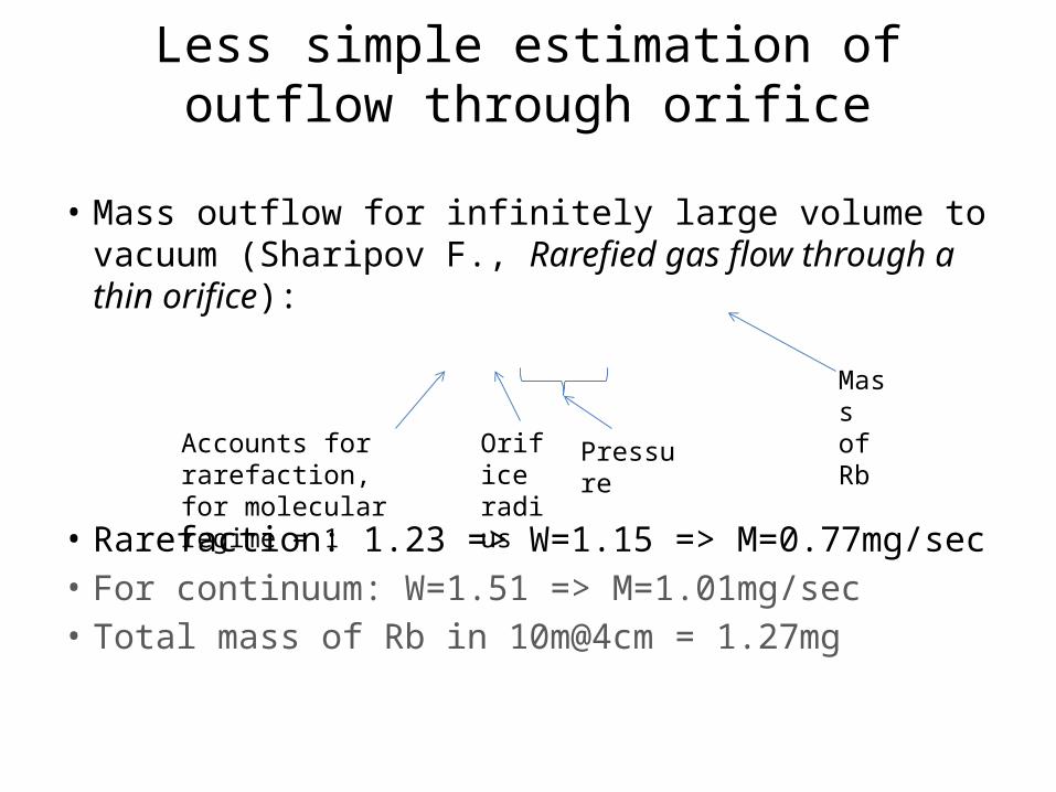
Less simple estimation of outflow through orifice
• Mass outflow for infinitely large volume to vacuum (Sharipov F., Rarefied gas flow through a thin orifice):
• Rarefaction: 1.23 => W=1.15 => M=0.77mg/sec• For continuum: W=1.51 => M=1.01mg/sec• Total mass of Rb in 10m@4cm = 1.27mg
Accounts for rarefaction,for molecular regime = 1
Orifice radius
Pressure
Mass of Rb

Summary of leak rate values
• Molecular flow theory: 0.67mg/sec• Rarefied flow: 0.77mg/sec• Continuum flow: 1.01mg/sec• Simple continuum estimation: 1.09mg/sec
• Simulation: 0.52mg/sec
Possible explanation of error: we don’t have infinitely large volume
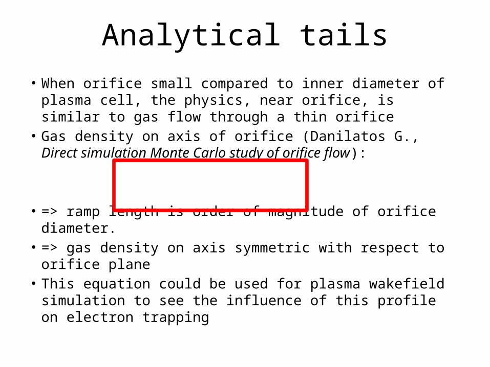
Analytical tails• When orifice small compared to inner diameter of plasma
cell, the physics, near orifice, is similar to gas flow through a thin orifice
• Gas density on axis of orifice (Danilatos G., Direct simulation Monte Carlo study of orifice flow):
• => ramp length is order of magnitude of orifice diameter.• => gas density on axis symmetric with respect to orifice
plane• This equation could be used for plasma wakefield simulation
to see the influence of this profile on electron trapping

3D DSMC simulation Double Orifice no Source: boundary conditions
The idea : To have large volume between both orifice to drive outflow to gain some time
Symmetry wall
Thermal wall
50cm
4cm 1cm 20cm
4cm
Fast valve

3D DSMC simulation Double Orifice no Source: density profile (1e6 particles)
0
500
1000
1500
2000
0 0.1 0.2 0.3 0.4 0.5 0.6 0.7 0.8
0.00ms
0
500
1000
1500
2000
0 0.1 0.2 0.3 0.4 0.5 0.6 0.7 0.8
0.66ms
0
500
1000
1500
2000
0 0.1 0.2 0.3 0.4 0.5 0.6 0.7 0.8
1.33ms
0
500
1000
1500
2000
0 0.1 0.2 0.3 0.4 0.5 0.6 0.7 0.8
4.65ms
0
500
1000
1500
2000
0 0.1 0.2 0.3 0.4 0.5 0.6 0.7 0.8
9.96ms
0
500
1000
1500
2000
0 0.1 0.2 0.3 0.4 0.5 0.6 0.7 0.8
15.3ms
0
500
1000
1500
2000
0 0.1 0.2 0.3 0.4 0.5 0.6 0.7 0.8
19.9ms
0
500
1000
1500
2000
0 0.1 0.2 0.3 0.4 0.5 0.6 0.7 0.8
25.2ms
0
500
1000
1500
2000
0 0.1 0.2 0.3 0.4 0.5 0.6 0.7 0.8
30.0ms
Approximately 15cm at 30ms

3D DSMC simulation Double Orifice no Source: density profile (1e7 particles)
0
2000
4000
6000
8000
10000
12000
14000
0 0.1 0.2 0.3 0.4 0.5 0.6 0.7 0.8
0.00ms
0
2000
4000
6000
8000
10000
12000
14000
0 0.1 0.2 0.3 0.4 0.5 0.6 0.7 0.8
0.66ms
0
2000
4000
6000
8000
10000
12000
14000
0 0.1 0.2 0.3 0.4 0.5 0.6 0.7 0.8
1.33ms
0
2000
4000
6000
8000
10000
12000
14000
0 0.1 0.2 0.3 0.4 0.5 0.6 0.7 0.8
5.31ms
0
2000
4000
6000
8000
10000
12000
14000
0 0.1 0.2 0.3 0.4 0.5 0.6 0.7 0.8
9.96ms
0
2000
4000
6000
8000
10000
12000
14000
0 0.1 0.2 0.3 0.4 0.5 0.6 0.7 0.8
15.3ms
0
2000
4000
6000
8000
10000
12000
14000
0 0.1 0.2 0.3 0.4 0.5 0.6 0.7 0.8
19.9ms
0
2000
4000
6000
8000
10000
12000
14000
0 0.1 0.2 0.3 0.4 0.5 0.6 0.7 0.8
25.2ms
0
2000
4000
6000
8000
10000
12000
14000
0 0.1 0.2 0.3 0.4 0.5 0.6 0.7 0.8
29.9ms
Approximately 15cm at 30ms

0
2000
4000
6000
8000
10000
0 0.1 0.2 0.3 0.4 0.5 0.6 0.7 0.8
3D DSMC simulation Double Orifice no Source: density profile (1e7 particles)
Density profile integrated over last 4ms (25.9-29.9ms) in order to increase statistics:
Red line: theory for infinitely large volumeBlue lines: orifice 1 and 2

3D DSMC simulation Double Orifice no Source: density profile (1e7 particles)
Time, sec
Den
sity
in p
lasm
a ce
ll, a
.u.

3D DSMC simulation Single Orifice with Source: boundary conditions
Symmetry wall
Thermal wall
Source (constant flux)
50cm
4cm 1cm
20cm
2cm
2cm
DSMC: hard sphere model

3D DSMC simulation Single Orifice with Source: results
-0.2
-0.15
-0.1
-0.05
0
0.05
0 0.1 0.2 0.3 0.4 0.5 0.6 0.7 0.8
Final data
Convergence reached at around 0.5sec (with plasma cell tube initially filled)
Simulation inflow (=outflow): 0.52mg/sec. This equivalent to 45g/day.If orifice will be open only 3 seconds each 30 seconds: 4.5g/day.

3D DSMC simulation Single Orifice with Source: density profile
0
500
1000
1500
2000
2500
3000
3500
4000
0 0.1 0.2 0.3 0.4 0.5 0.6 0.7 0.8
Density profile in the center of plasma cell (inside r=4mm)

3D DSMC simulation Double Orifice with Source: boundary conditions
Symmetry wall
Thermal wall
Source (constant flux)
50cm
4cm 1cm
10cm
2cm
2cm2cm
The idea of second orifice: 1. Prevent any possible vortex creation2. Both orifices are symmetrically placed with respect to
source tube => the symmetry simplifies the understanding of problem (in case with low collisions between particles, it could be considered as superposition of source and two orifices with plasma cell with orifice at the end

3D DSMC simulation Double Orifice with Source: results
-0.1
-0.08
-0.06
-0.04
-0.02
0
0.02
0.04
0 0.1 0.2 0.3 0.4 0.5 0.6 0.7 0.8
Final data
0
1000
2000
3000
4000
5000
0 0.1 0.2 0.3 0.4 0.5 0.6 0.7 0.8
Results are very similar to the simulation with single orifice: leak rate: 0.52mg/sec
convergence: 0.5sec
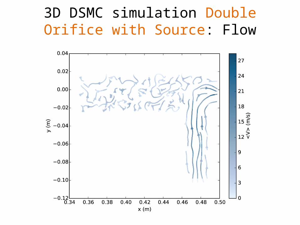
3D DSMC simulation Double Orifice with Source: Flow
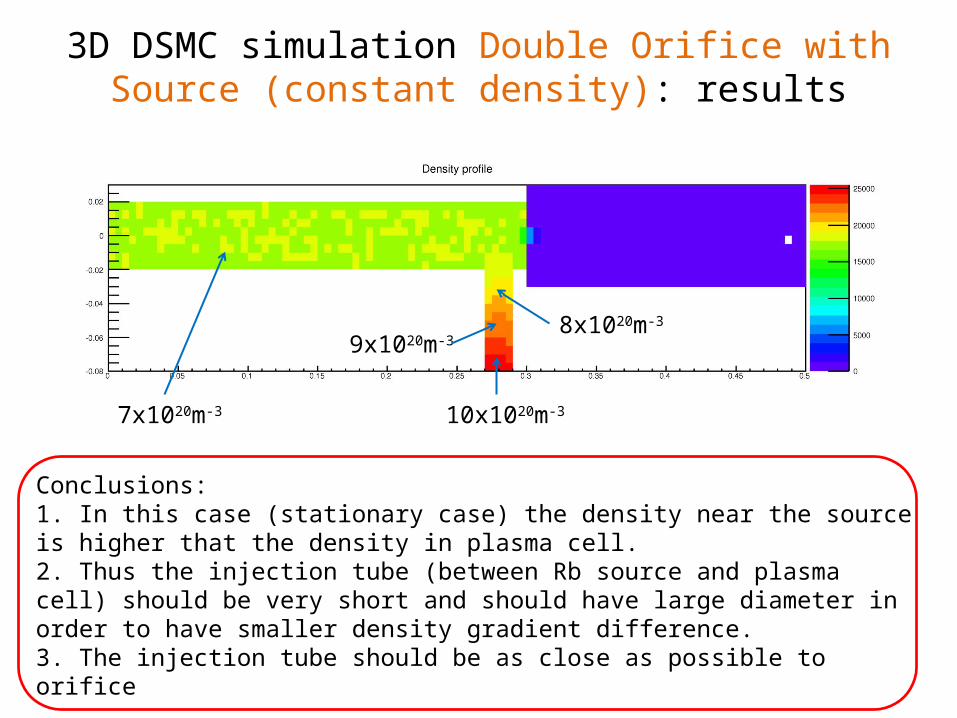
3D DSMC simulation Double Orifice with Source (constant density): results
7x10²⁰m-3 10x1020m-3
8x10²⁰m-3
9x10²⁰m-3
Conclusions: 1. In this case (stationary case) the density near the source is higher that the density in plasma cell.2. Thus the injection tube (between Rb source and plasma cell) should be very short and should have large diameter in order to have smaller density gradient difference.3. The injection tube should be as close as possible to orifice
Challenge 1
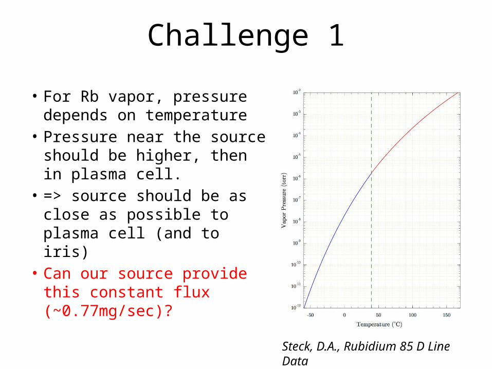
• For Rb vapor, pressure depends on temperature
• Pressure near the source should be higher, then in plasma cell.
• => source should be as close as possible to plasma cell (and to iris)
• Can our source provide this constant flux (~0.77mg/sec)?
Steck, D.A., Rubidium 85 D Line Data

Temperature, K
Den
sity
, 1020
m-3
Surf
ace,
m2
Flux = 0.77mg/sec
Evaporation rate
Pound G.M., Selected Values of Evaporation and Condensation Coefficients for Simple Substances
𝐽=𝛼𝑛𝑘𝑇 −𝑝𝑒𝑞
√2𝜋𝑚𝑘𝑇 𝑝𝑒𝑞=101325×10(4.312− 4040
𝑇 )

Challenges: 2• If we going to have orifice system (or source
system) from both ends of plasma cell => the both sources should be perfectly aligned (to avoid density ramp)
Future work
• Simulate source with constant density instead of constant flow
• Simulation with fine grid• Simulation with variable hard sphere model• Experiment to verify simulation

Summary
+ Steady state solution- Constant Rb loss of 0.52mg/sec+ Good agreement with theory+ Sharp gradient density profile (in agreement with theory)? Could our source provide this flux?? Is our source stable enough for this solution?
- Fast valve should be used+ Gradient density profile length of ~15cm for up to 30ms+ With Rb source the gradient should be even sharper+ If our source is not very stable, this solution will work- Density is not uniform after 10ms.

Possible practical application
Source (constant flux)
10m
Valve 1Valve 2
Questions: 1. If valve 1 and 2 close, what is the time to fill this volume with Rb source from one end? (Initially plasma cell is empty!) (for particular geometry it is > 5sec)2. If valve 2 is closed and valve 1 is open, what is the time to reach the equilibrium? (Initially plasma cell is filled with Rb!) (for particular geometry it is > 8sec, see next slide)
Total mass of Rb in 10m@4cm = 1.27mg. Flow through orifice = 0.52 - 0.77mg/sec

If valve 2 is closed and valve 1 is open time to reach the equilibrium?
Preliminary ResultsIn particular geometry!!!
Den
sity
in p
lasm
a ce
ll, a
.u.
Time, ms

Possible closed loop Rb vapor system:
A valve which isnormally closedand opened tolet beams pass.It’s not necessaryfor this valve tobe leak tightand fast.
At 70 °C equilibrium vapor pressure of Rb is 2000 times lower than at 200 °C.
Rb in this system is in the closed loop because it’s either in a liquid or in a vapor form.
The amount of liquid Rb in the reservoir can be limited to ~10 cm3 (15 g). The main question is how much liquid Rb will stick to 70 °C walls before it starts to flow down to the reservoir? Let’s assume the 70 °C surface is ~ πR2 = 3.14*(10 cm)2 = 300 cm2 and Rb layer is 1 mm thick => V = 300 cm2 * 0.1 cm = 30 cm3 => The total mass of Rb is likely to be below 100 g.
Rb flow is 0.5 mg/sec = 100 g / 2 days =>Another option may be a cycled operation – 70 °C tank will be heated up once a day or so.
R ~ 10 cm
Rb70 °C
200 °C oil tank
190 °C
70 °C