Deliverable Number 2.1 Description of selected FCH systems ... Description of selected... ·...
62
Grant agreement No: 325348 Deliverable Number – 2.1 Description of selected FCH systems and infrastructure, relevant safety features and concepts Status: Final Version Dissemination level: PU - Public Partner responsible for the deliverable: ALAB Contributing partners: ALAB, ENSOSP, CRISIS, ASE, UU
Transcript of Deliverable Number 2.1 Description of selected FCH systems ... Description of selected... ·...

Grant agreement No: 325348
Deliverable Number – 2.1
Description of selected FCH systems and infrastructure, relevant safety
features and concepts
Status: Final Version
Dissemination level: PU - Public
Partner responsible for the deliverable: ALAB
Contributing partners: ALAB, ENSOSP, CRISIS, ASE, UU

Authors: Name1: François Laumann Name2: Franck Verbecke Name2: Audrey Duclos Name3: Adrien Zanoto Name3: Li Zhiyong
1 Partner organisation: ENSOSP 2 Partner organisation: ASE 3 Partner organisation: ALAB 3 Partner organisation: UU Author printed in bold is the contact person for this document. Date of this document: 15 June 2015 File name: D2.1_HYRESPONSE_ Description of selected FCH systems and infrastructure, relevant safety features and concepts _v5.doc Document history
Revision Date Modifications made Author(s)
Template dd/mm/yyyy XXXXXX XXXX
V1 04/09/3013 Adrien Zanoto
V2 27/06/2014 Franck Verbecke &
Audrey Duclos
V3 09/09/2014 University of Ulster contribution Li Zhiyong & Svetlana
Tretsiakova-McNally
V4 10/11/2014 ENSOSP contribution François Laumann
V5 11/06/2015 Midterm review comment Adrien Zanoto
V6 14/06/2015 Comments and changes made for the
revised version V5
Svetlana Tretsiakova-
McNally

Table of Contents
1. Glossary 5
2. Introduction 6
3. Hydrogen production 7
3.1. PEM hydrogen electrolyzer 7
3.1.1. Description 7
3.1.2. Safety features and concepts 9
3.2. Alkaline electrolysers 10
3.2.1. Description 10
3.2.2. Safety features and concepts 12
3.3. Reformer 13
3.3.1. Description of technology 13
3.3.2. Safety features and concepts 13
4. Stationary hydrogen storage 14
4.1. Gaseous hydrogen storage in racks or cylinders 14
4.1.1. Description 14
4.1.2. Safety features and concepts 15
4.2. Gaseous hydrogen tanks 15
4.2.1. Description 15
4.2.2. Safety features and concepts 16
4.3. Liquefied hydrogen storage 16
4.4. Hydride solid hydrogen storage 16
5. Hydrogen distribution applications (materials handling) 17
5.1. Hydrogen transport by road 17
5.1.1. Gaseous trucks 17
5.1.2. Cryogenic liquid trucks 19
5.2. Pipe 20
5.2.1. Description 20
5.2.2. Safety features and concepts 23
6. FC vehicles 23
6.1. FC cars 24
6.1.1. Description 24
6.1.2. Safety features and concepts 26
6.2. FC Buses 28
6.2.1. Description 28
6.2.2. Safety features and concepts 30
6.3. Forklift 31
6.3.1. Description 31
6.3.2. Safety features and concepts 32

7. Hydrogen refueling stations 33
7.1. Description 33
7.1.1. Operating principle 33
7.1.2. Compressor 34
7.1.3. HP Storage (or "buffer") 35
7.1.4. Connecting pipework 35
7.1.5. The dispenser 35
7.1.6. Description of the different operating modes 36
7.2. Safety features and concepts 37
7.2.1. Outdoor area 37
7.2.2. Connecting pipework 38
7.2.3. Dispenser 38
8. FC stationary applications 39
8.1. Combined production of Heat and Power (CHP) system 39
8.2. Stationary back-up power generation 39
8.2.1. Principle and functioning of the fuel cell 39
8.2.2. Example of FC stationary application: Backup system connected to a
datacenter 40
8.2.3. Safety features and concepts 42
9. Decentralized hydrogen production 45
9.1. Hydrogen-based energy storage system (Greenergy Box) 45
9.1.1. Description 45
9.1.2. Safety features and concepts 46
9.2. Example of existing project: MYRTE platform 49
9.2.1. Description of the platform 49
9.2.2. Example of intervention map for Fire and Rescue services 52
9.3. JANUS 55
9.3.1. Description of the project 55
9.3.2. Key safety devices and concept of the overall installation 58
10. References 62

1. Glossary
INERIS National Institute for the Industrial Environment and Risks
MMR Measurement and control of risks
NWP Nominal working pressure
PAC Fuel cell
PEM Proton Exchange Membrane
PhD Hazardous phenomena
PRD Pressure Relief Device or thermal fuse activated when a
pressure threshold is exceeded
SEI Irreversible effects threshold
SEL Lethal effects threshold
SELS Significant lethal effects threshold
TRD Thermally activated Relief Device or thermal fuse activated
when a temperature threshold is exceeded

2. Introduction
The development of new hydrogen and fuel cell (FCH) technologies require a better understanding
by first responders the risks associated with hydrogen.
Hydrogen production methods (e.g. electrolysis or natural gas reforming), its storage, refuelling
stations, FC vehicles (e.g. cars, buses, forklifts) and hydrogen-based energy storage systems remain
unknown to first responders. In addition, there are no standardized procedures for intervention in
the event of possible accidents or incidents.
It is quite likely that first responders would deal with accidents/incidents on FCH systems and
infrastructures, for which they neither have sufficient knowledge nor technical documentation,
which will assist them in the better understanding of certain critical situations. Taking into account
specific risks related to FCH technologies in general and to hydrogen gas in particular it is very
important to provide first responders with the description of the technical elements of the selected
FCH systems in order for them to evaluate/assess the risk situations properly.
Indeed, the standardization and uniformity of safety devices for first responders do not yet exist. The
first responders are expected to have permanently and easily exploitable document view of a guide
to better understand the situation in the presence of hydrogen.
It is essential to create a common language between industrials and first responders to facilitate
collaboration which help the integration of first responder’s difficulties during the design phase.
This document represents the work carried out within task 2.1-Selection, analysis and description of
the HFC applications, their safety concepts and safety feature (WP2). It does not purport to be
complete but will allow the first responders to find the essential information on elements of FCH
installation or equipment that will be needed for basic understanding and appropriate decision
making.

3. Hydrogen production
Hydrogen can be produced by water electrolysis or steam reforming of a natural gas.
3.1. PEM hydrogen electrolyser
3.1.1. Description
Figure 3-1: Overview of the process
PEM Electrolyser converts electrical energy into chemical energy and can be seen as the opposite
device of the Fuel Cell (see $7.2.1). Conversion takes place in two rooms which are separated by a
Proton Exchange Membrane (PEM). By application of a continuous tension, water is dissociated out
of hydrogen (H2) at the negative pole and oxygen (O2) at the positive pole (Figure 3-2). The gases are
collected in containers of recovery.
Figure 3-2: Functioning of an Electrolyser type PEM.

The electrolyser includes:
- A process cabinet gathering all the process components (valves, piping, gases and water,
stack, pressurized vessels, pumps, etc.)
- An electrical cabinet gathering all electrical components (Instrumentation and control,
cabling, power conditioning).
- A cooling system for electrolysis process heat dissipation (no figured in the view here
below).
Figure 3-3: Technical specification and picture of AREVA Stockage d’Energie New Stack PEMFC generation.
In a practical way, the electrodes (anode and cathode) and the membrane are associated to form a
Membrane Electrode Assembly called MEA and a stacking of Fuel Cell is called a stack.
This system will comprise a weather-proof container enclosing (Figure 3-4):
- an electrolyser that uses electricity to split water into hydrogen and oxygen;
- control system and automation;
- thermal management system (water/air heat exchanger);
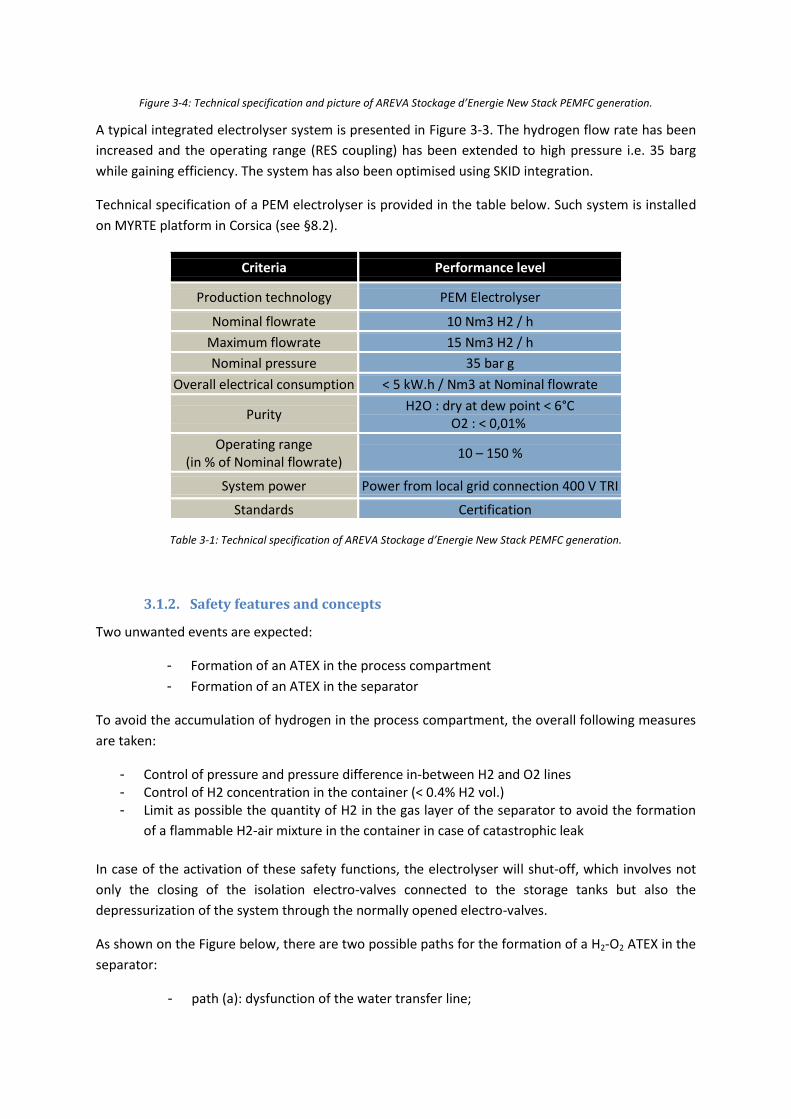
Figure 3-4: Technical specification and picture of AREVA Stockage d’Energie New Stack PEMFC generation.
A typical integrated electrolyser system is presented in Figure 3-3. The hydrogen flow rate has been
increased and the operating range (RES coupling) has been extended to high pressure i.e. 35 barg
while gaining efficiency. The system has also been optimised using SKID integration.
Technical specification of a PEM electrolyser is provided in the table below. Such system is installed
on MYRTE platform in Corsica (see §8.2).
Criteria Performance level
Production technology PEM Electrolyser
Nominal flowrate 10 Nm3 H2 / h
Maximum flowrate 15 Nm3 H2 / h
Nominal pressure 35 bar g
Overall electrical consumption < 5 kW.h / Nm3 at Nominal flowrate
Purity H2O : dry at dew point < 6°C
O2 : < 0,01%
Operating range (in % of Nominal flowrate)
10 – 150 %
System power Power from local grid connection 400 V TRI
Standards Certification
Table 3-1: Technical specification of AREVA Stockage d’Energie New Stack PEMFC generation.
3.1.2. Safety features and concepts
Two unwanted events are expected:
- Formation of an ATEX in the process compartment
- Formation of an ATEX in the separator
To avoid the accumulation of hydrogen in the process compartment, the overall following measures
are taken:
- Control of pressure and pressure difference in-between H2 and O2 lines - Control of H2 concentration in the container (< 0.4% H2 vol.) - Limit as possible the quantity of H2 in the gas layer of the separator to avoid the formation
of a flammable H2-air mixture in the container in case of catastrophic leak
In case of the activation of these safety functions, the electrolyser will shut-off, which involves not
only the closing of the isolation electro-valves connected to the storage tanks but also the
depressurization of the system through the normally opened electro-valves.
As shown on the Figure below, there are two possible paths for the formation of a H2-O2 ATEX in the
separator:
- path (a): dysfunction of the water transfer line;
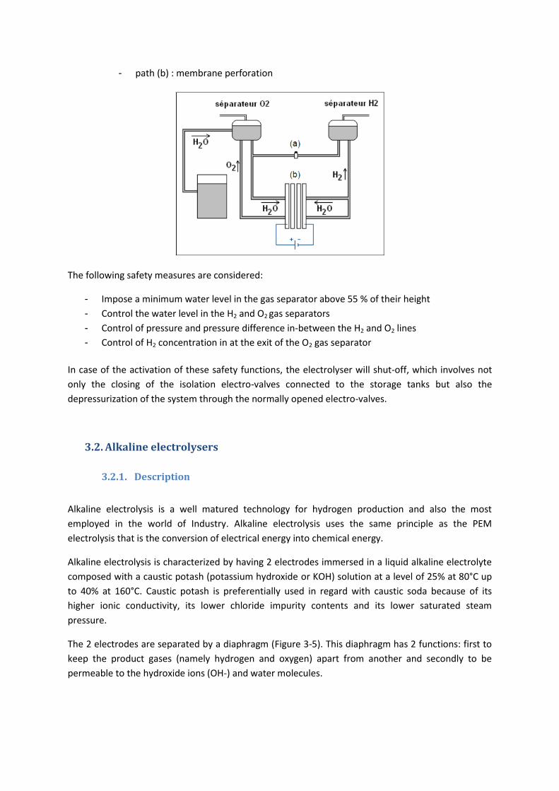
- path (b) : membrane perforation
The following safety measures are considered:
- Impose a minimum water level in the gas separator above 55 % of their height
- Control the water level in the H2 and O2 gas separators
- Control of pressure and pressure difference in-between the H2 and O2 lines
- Control of H2 concentration in at the exit of the O2 gas separator
In case of the activation of these safety functions, the electrolyser will shut-off, which involves not
only the closing of the isolation electro-valves connected to the storage tanks but also the
depressurization of the system through the normally opened electro-valves.
3.2. Alkaline electrolysers
3.2.1. Description
Alkaline electrolysis is a well matured technology for hydrogen production and also the most
employed in the world of Industry. Alkaline electrolysis uses the same principle as the PEM
electrolysis that is the conversion of electrical energy into chemical energy.
Alkaline electrolysis is characterized by having 2 electrodes immersed in a liquid alkaline electrolyte
composed with a caustic potash (potassium hydroxide or KOH) solution at a level of 25% at 80°C up
to 40% at 160°C. Caustic potash is preferentially used in regard with caustic soda because of its
higher ionic conductivity, its lower chloride impurity contents and its lower saturated steam
pressure.
The 2 electrodes are separated by a diaphragm (Figure 3-5). This diaphragm has 2 functions: first to
keep the product gases (namely hydrogen and oxygen) apart from another and secondly to be
permeable to the hydroxide ions (OH-) and water molecules.

Figure 3-5: Functionning of the alkaline electrolysis
The reaction is:
At the anode:
2 OH- → ½ O2 + H2O + 2 e-
At the cathode:
2 H2O + 2 e- → H2 + 2 OH-
Total reaction: H2O → H2 + ½ O2
A typical alkaline electrolysis is composed of:
Power supply and System of control and instrumentation,
Electrolysis system (with unit of water purification, one of hydrogen purification, gas
dryer, separators…)
Compressor.
The figures below are examples of industrial alkaline electrolysers.
Figure 3-6: Alkaline electrolyser IHT type S-556, 760 Nm3/h and 30 bars

Figure 3-7: Outdoor and Indoor HySTAT from Hydrogenics, 10-60Nm3/h
3.2.2. Safety features and concepts
Same as PEM electrolyser, the main risks regarding the system are the formation of a
hydrogen/oxygen mixture and then an internal explosion within the electrolyser.
Thus, some sensors are implemented (see the list below) in order to detect an electrolyser
dysfunction:
- Measurement of the hydrogen concentration in the oxygen line,
- Measurement of tension,
- Measurement of the temperature at the entry and at the outflow of electrolysis cells,
- Measurement of the ionic concentration of the electrolyte.
Another risk is this one of the exposition to a corrosive product in the event of an electrolyte leak.
The specification sheet of potassium hydroxide recommends the use of a leak tank in order to avoid
the contact of caustic potash with the environment.

3.3. Reformer
3.3.1. Description of technology
Figure 3-8: Overviews of the process and photography of the installation
Most of the time, reformer is used in industrial application. It produces hydrogen from natural gaz,
(CH4) steam and heat. The capacity ranges from a few 100 to more than 100 000 Nm3/h. It can be
operate all a year (7 days a week, 24 hours) and at constant load.
It took time (few days) to start it up, the process emits CO2 and produced hydrogen is not very clean
and is at atmospheric pressure.
3.3.2. Safety features and concepts
This technology is well established so there are no specific concerns.

4. Stationary hydrogen storage
The storage of large quantities of hydrogen for long times is a key step in the build-up of
infrastructure in order to regulate the hydrogen consumption and production and ensure continuity
in supply. Various underground hydrogen storage schemes are investigated. One option is to store
gaseous hydrogen in geological formations including depleted gas fields or aquifers, caverns …
Another one is the underground storage in buried tanks, either in compressed gas form or in liquid
form. Geologic storage is generally close to hydrogen production site, buried tanks are close to point
of use such as refueling stations.
4.1. Gaseous hydrogen storage in racks or cylinders
4.1.1. Description
Cylinders could have different size and pressure. Most of them have a volume of 50 liters and are
under 200 bar (could be 300 bar). As the example below, there are plenty of different cylinders:
For different application, cylinders could be interconnected in a bundle. Size and volume could be
very different: from 20l to 300l from 200 bar to 700 bar.

Bundle Basket for transportation
4.1.2. Safety features and concepts
This technology is well established so there are no specific concerns. In Europe, most of
transportable cylinders have only a valve as safety barrier. In USA, for instance there is TRD on
transportable combustible cylinders. This prescription is more and more controversial because they
often create leak.
4.2. Gaseous hydrogen tanks
4.2.1. Description
The photo below presents the storage zone of the MYRTE platform (see §9.2).

4.2.2. Safety features and concepts
The photo below highlights typical location of the safety manual valves as closed as possible to the
storage tank.
Each storage tank is equipped by a pressure relief device (PRD) connected to a vent. The tare
pressure of the pressure relief valve is set so that the PRD actuates when the pressure within the
reservoir reaches 1.15 of the maximal operating pressure.
Isolation valves with lock out capabilities are used to isolate portions of the pipe line in emergencies
or for routine maintenance and inspection. These are installed should be installed in an accessible
location since they may need to be manually closed on an emergency basis.
In case of power outrage or emergency stop, each storage tank is isolated by the electro-valves
located close to each reservoir.
Non return valves, that are specifically designed to permit flow in one direction and to stop it in the
reverse direction, may also be used in piping and storage systems.
Flow excess valves may also be used to stop massive leaks in case of catastrophic pipe rupture.
4.3. Liquefied hydrogen storage
Not addressed within HyResponse because it is not the main stream.
4.4. Hydride solid hydrogen storage
Not addressed within HyResponse because it is not the main stream.

5. Hydrogen distribution applications (materials handling)
5.1. Hydrogen transport by road
5.1.1. Gaseous trucks
5.1.1.1. Description
Status
Truck fleets are currently used by industrial gas companies to transport seamless steel vessels of
compressed gaseous hydrogen for short distances (200-300 km) and small users (1 to 50 m3/h) from
centralized production. Single cylinder bottles, multi-cylinder bundles or long cylindrical tubes are
installed on trailers (Figure 5-1). Storage pressures range from 200 to 300 bar and a trailer can carry
from 2,000 to 6,200 Nm3 of H2 for trucks subject to weight limitation of 40 tons. The amount of
hydrogen carried out is thus relatively small (from 180 to 540 kg, depending on the number of tubes
or bundles), which represents ~ 1 to 2 % of the total mass of the truck. Current trailers utilize Type I
storage cylinders (all-metal). To increase performance, bundles of light-weight composite hoop
wrapped cylinders or tubes (Type II) can be used.
Figure 5-1: Two types of compressed gas hydrogen trailers operated by Air Liquide in Europe : tube trailer carrying 2,000 to
3,000 Nm3 of H2 (depending on the numbers of tubes) and Type II composite cylinder trailers carrying 6,200 Nm3 of H2
(540 kg)
The main cost factors in compressed gas truck delivery are capital costs, operation and maintenance
including drivers' labor and fuel costs. The amount of time the trailer is stored at customer site is
also a factor affecting delivery cost. The capital investment is low for small quantities of H2 but it
does not benefit of economy of scale with increasing demand and the costs increase linearly with
delivery distance. This mode of delivery is relatively easy but it has to be adapted to hydrogen
quantities and distances to be cost competitive.
Perspectives
The supply by gaseous truck (tube trailer, cylinders) is one of the most mature modes, preferred for
short distances and small amounts of hydrogen. Limitations are the low weight storage capacity for
high customer consumptions (requiring frequent delivery) and the low pressure of hydrogen
delivered, which requires additional compression at the fuelling station site. Thus, alternative

technologies with higher pressure, higher hydrogen-carrying capacity and lower-cost systems are
investigated as described hereafter.
Lincoln Composites develops higher volume tubes in composite structure (plastic liner fully wrapped
with epoxy impregnated carbon fiber) for hydrogen gaseous tube trailer delivery. The TITANTM tank
(1.08 meters in diameter, 11.5 meters in length, 8,400 liters in water volume, and 2,087 kg in weight)
operating at 250 bar can deliver 2 to 3 times the amount of hydrogen of a steel tank of similar mass.
Figure 5-2 shows the storage unit holding 4 tanks capable of storing 600 kg H2 at 250 bar. Higher
pressure tanks up to 350 bar are planned for 2010.
Figure 5-2: Container with 4 composite tanks developed by Lincoln Composites. Source: Lincoln Composites [20]
Hybrid technologies are explored at the Lawrence Livermore National Laboratory (LLNL) such as
cryo-compression combining pressure and low temperature to increase the amount of hydrogen
that can be stored per unit volume and avoid the energy penalties associated with hydrogen
liquefaction. Compressed hydrogen gas at cryogenic temperatures is much denser than in regular
compressed tanks at ambient temperatures. These new vessels would have the potential to store
hydrogen at temperatures as low as 80 K under pressures of 200-400 bar. This approach requires
development of insulated pressure composite tanks. Alternatively one could consider using cold
hydrogen gas tanks that would require less cooling. There may be some optimum combination of
pressure and temperature over the range of 80-200 K. Recently, LLNL has identified inexpensive
glass fiber materials for cold hydrogen gas storage (~ 150 K and up to 500 bar), expecting 50% trailer
cost reduction.
5.1.1.2. Safety features and concepts
The main safety device for on road gas storage is manual safety valves:
- according to ADR1, during transportation all storage are isolated by a valve;
- in service, there is different safety devices & procedures:
o The semi-trailer changeover procedure takes place as follows:
The driver parks the semi-trailer in the location provided, The driver put chocks in position and deploys the leg stand, The driver unhitches the tractor unit,
1 ADR: Accord for dangerous goods by road

The driver connects the hose from the full semi-trailer, tests the seal on the draw-off hose and disconnects the empty semi-trailer,
The driver hitches the empty semi-trailer to the tractor unit and departs.
o A manual leak tightness test when connecting to a semi-trailer. This is done in the
following stages. The operator connects the semi-trailer hose to the installation's
connection post. Hose is pressurised. The operator Check for leak tightness using
detection soap and stabilisation of the pressure measured locally using a pressure
gauge.
5.1.2. Cryogenic liquid trucks
5.1.2.1. Description
Hydrogen can be transported by road in liquid form (cooled to 20 K or – 253 °C) to distribute larger
quantities (hundreds of m3/h). In terms of weight capacity, super-insulated liquid hydrogen trucks
can transport up to 10 times more hydrogen than the tube trailers used for conveying compressed
gas. Liquid H2 trucks (Figure 5-3) operating at atmospheric pressure have volumetric capacities of
about 50,000 – 60,000 liters and can transport up to 4,000 kg with a mass truck of ~ 40 tons. It is a
preferred distribution mode for medium/large amounts of hydrogen and long distances, which
explains the liquid H2 business has been developed most extensively in North America (the hydrogen
liquefaction capacity in North America is about ten times larger than in Europe). The liquid hydrogen
transported in the truck is then vaporized to a high-pressure product for use at the customer site.
Figure 5-3: Road tanker operated by Air Liquide for conveying liquid hydrogen to user. Source: Air Liquide Image Bank
A main issue of this pathway is the liquefaction plant which is capital-intensive. Then, the
liquefaction process is costly. The electricity input for liquefaction accounts for ~ 35 % of the lower
heating value of hydrogen (compared to ~ 10 % for gas compression). Electricity costs account for
50-80 % of the liquefaction costs.
Distance is the chief deciding factor between liquid and gaseous hydrogen. The number of liquid
trucks will depend on the hydrogen demand and the localization of the liquefaction point. However,
the liquid truck capacity being much higher than that of a compressed gas truck, this mode of
delivery is less dependent upon the transport distance. The truck capital cost and operating cost
(fuel, labour) are much smaller. As a consequence, liquid trucking is more economical than gaseous
trucking for long distances (from approximately 400 km to thousands of kilometers) and medium
amounts of hydrogen.

However, one has to consider the availability of liquid hydrogen. Currently, the industrial hydrogen
market is served by four liquefiers in Europe (the German's second H2 liquefaction plant started in
2007) and ten in North America. Larger markets would justify the construction of new liquid plants.
Significant cost reductions due to scaling effects of liquefaction equipment are possible. However,
this mode of delivery relies on the price of electricity and on the decision to install new liquefaction
units. Better technologies could offer opportunities to reduce capital cost, improve energy efficiency
of liquefaction process and reduce the amount of hydrogen lost due to boil-off during storage and
transportation (the evaporation rate which depends on the size, shape, insulation of the container
and time of storage, is typically of the order of 0.2 %/day for 100 m3 container). Studies are
underway to improve liquefaction technologies and propose novel approaches (for example,
improvement of ortho-para conversion, development of magnetic refrigeration …).
5.1.2.2. Safety features and concepts
This technology is not addressed within HyResponse because it is dedicated to industrial technology
and not to hydrogen energy applications. Nevertheless, we could precise that there is at least two
safety valves with at least one pneumatic. PRDs limits the risk of the boil-off.
5.2. Pipe
5.2.1. Description
Overview of hydrogen networks
A number of commercial hydrogen pipelines are used today to distribute large quantities (tens of
thousands of m3/h) of gaseous hydrogen to the industrial market. Their lengths range from less than
a kilometer to several hundreds of kilometers. The major actors are the industrial gas companies,
namely Air Liquide, Air Products, Linde and Praxair. In response to an increased demand for
hydrogen by refining customers, existing networks are expanding and new portions are built (in
March 2009, Air Products, as an example, announced a 60-km extension to the U.S. Gulf Coast
hydrogen pipeline network in Louisiana). The hydrogen network is estimated at around 1600 km in
Europe and 1,100 km in North America. Most of the pipelines are located where large quantities of
hydrogen are consumed in refining and chemical sectors. These include systems in the North of
Europe, (covering The Netherlands, Northern France and Belgium), Germany (Ruhr and Leipzig
areas), UK (Teesside) and in North America (Gulf of Mexico, Texas-Louisiana, California, Alberta).
Smaller systems also exist in South Africa, Brazil, Thailand, Korea, Singapore and Indonesia. Overall,
these pipeline lengths are tiny when compared to the worldwide natural gas transport pipeline
system, which would exceed 2,000,000 km.
Figure 1 displays parts of the worldwide H2 pipeline network. For example, the 240 km long pipeline
in the Ruhr area of Germany (Figure 5-4-a) acquired by Air Liquide in 1998 has been in operation
since 1938.

a b
C d
e
Figure 5-4: Main hydrogen pipelines in the world. (a) Air Liquide hydrogen pipelines in Benelux, France and Germany (Ruhr
area). (b) Air Liquide hydrogen pipelines in the Gulf Coast (USA). (c) Linde hydrogen pipelines in Germany. (d) Praxair
hydrogen pipelines in the Gulf coast (USA). (e) Air Product hydrogen pipelines in the Gulf Coast (USA)
Within the “Zero Regio” European project for hydrogen energy applications, Linde has installed a
900 bar hydrogen pipeline (of 1” diameter) over a distance of 1.7 km in the Frankfurt-Hoechst
industrial park to supply fuel cell passenger vehicles.

Pipeline characteristics
Pipelines require adequate design, installation and maintenance procedures. The operating pressure
of hydrogen pipelines is generally lower than 100 bar (most commonly between 40 and 70 bar) and
the diameter of the pipelines (D) usually ranges from 10 to 300 mm. Current pipelines are made of
steels. A technical concern is hydrogen embrittlement of metallic pipelines and welds, characterized
by a loss of ductility and rupture when subjected to stress. The steels used for H2 pipelines are thus
low-carbon, low-alloy and low strength steels to reduce the risk of embrittlement (e.g., API X42 steel
with C < 0.2, Mn < 1.3 wt%). These steels combine economical affordability with an adequate range
of physical properties such as strength, toughness, ductility and weldability. For safety reasons, most
pipelines are buried so steels are protected by coatings or cathodic protection to prevent corrosion
issues.
Pipeline construction involves extensive welding for joining, with a minimum of inspections before
operation for safety considerations. The exploitation of a pipeline network also requires compressor
stations as hydrogen is generally available at low pressure. Hydrogen compressors feeding the
pipeline system are usually found at locations where hydrogen is produced. The compressors are
expensive and require a high maintenance so they are actually not installed if another alternative is
possible. For instance, when hydrogen is produced using natural gas (steam methane reforming), the
natural gas feedstock can be compressed and the production plant operated at a higher pressure.
Friction losses in pipelines with hydrogen are much lower than for those in natural gas as the
viscosity of hydrogen is smaller (the energy loss during transportation of hydrogen is about 4 % of
the energy content).
Perspectives of evolution for H2 pipelines
A hydrogen pipeline carries about 30% less energy compared to natural gas pipeline due to the
lower heating value of hydrogen. The distribution of larger energy quantities in hydrogen pipelines
requires a flow pressure increase (> 100 bar). This increase in pressure may have implications for the
material which could be used in the pipeline construction.
Furthermore, the operating conditions of a hydrogen pipeline for energy applications would be
different from an industrial pipeline which today operates at nearly constant pressures, without
significant pressure cycles or swings. Hydrogen energy pipelines would have to bear variations of
pressure. This may be a concern due to the susceptibility of steels to hydrogen embrittlement which
affects their mechanical properties and decreases their resistance to fatigue crack.
To address these challenges, there is a renewed interest in the research for new pipelines materials
compatible with hydrogen and their use at higher operating pressure, and to reduce capital costs.
New steels are explored to develop a better understanding of hydrogen embrittlement and to
identify steel compositions and processes suitable for construction of a new pipeline infrastructure
or potential use of the existing steel pipeline infrastructure.
Research also concentrates on alternative to metallic pipelines to achieve cost and performance
targets for hydrogen transmission and distribution. Polymeric and fiber-reinforced polymer pipelines

(FRP) which present the advantages of being light compared to steels, easier to handle, join and
weld, non-sensitive to corrosion, and non-sensitive to hydrogen embrittlement are investigated.
Polymeric pipes currently used in the natural gas distribution network are made of polyethylene and
have a pressure rating limited to 10 bar. Polymers such as polyamide (and more particularly
polyamide-12) present more interest as the permeability of hydrogen is significantly reduced and its
thermo-mechanical properties allow pipes to sustain a 20 bar operating pressure and a 80°C
operating temperature. Therefore, plastic pipes can be an alternative to steel thanks to savings in
installation and maintenance costs. However, material supply can represent a high ratio of the total
cost.
Figure 5-5: Composite pipeline (FRP) instrumented for testing
Pipes in composite materials (FRP) are composed of a thermoplastic liner (mainly polyethylene)
wrapped with high strength fibers (most commonly aramid fibers) then coated with a thermoplastic
layer. This last layer protects from environmental attacks and helps to retain the wrapping mainly
responsible for the mechanical properties. Compared to simple plastic pipes, wrapping with aramid
fibers allows getting pressure up to 100 bar. These reinforced plastic pipes are already used for
natural gas or crude oil distribution in the middle-east and their development for H2 delivery is
currently part of DOE Hydrogen program (Figure 5-5). According to literature, Fibre Reinforced
Plastic (FRP) pipes could be a cost-effective option compared to metallic pipes when long lengths can
be installed (200 to 300 meters). However the manufacturing process does not allow getting plastic
pipes with diameters as high as steel pipes (100 and 150 mm are most common diameter). Further
developments are still needed to evaluate the feasibility of large-scale manufacturing operations,
assess joining technology, and develop codes & standards for hydrogen-service FRP pipelines.
5.2.2. Safety features and concepts
This technology is not addressed within HyResponse because it is dedicated to industrial technology
and not to hydrogen energy applications. Pipelines are specific assets with their own safety
management system. Periodic inspections were performed following internal specifications: from
aboveground to detect coating defects or directly inside the pipeline to measure the steel metal loss.
Once a year all instrumentation and valves are checked which included corrosion protection,
painting, lubrication of gear drive, cleaning filters and strainers
5.3. FC cars
Most of the following information on Fuel Cell Hydrogen (FCH) cars is taken from the draft of GTR
document prepared by the Economic and Social Council, United Nations [1].
5.3.1. Description
Fuel cell hydrogen (FCH) cars have an electric drive train powered by a fuel cell that generates
electric power electrochemically using hydrogen. In general, FCH cars are equipped with other
advanced technologies that increase efficiency, such as regenerative braking systems that capture
the kinetic energy lost during braking and store it in a battery or ultra-capacitors. While the various
FCH cars are likely to differ in the details of the systems and hardware/software implementations,
the following major systems are common to most FCH cars:
(A) Hydrogen fuelling system;
(B) Hydrogen storage system;
(C) Hydrogen fuel delivery system;
(D) Fuel cell system;
(E) Electric propulsion and power management system.
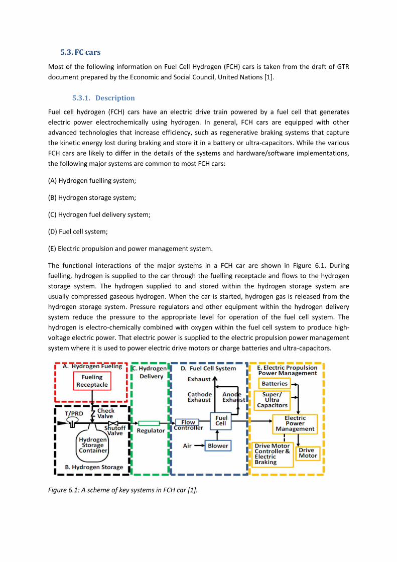
The functional interactions of the major systems in a FCH car are shown in Figure 6.1. During
fuelling, hydrogen is supplied to the car through the fuelling receptacle and flows to the hydrogen
storage system. The hydrogen supplied to and stored within the hydrogen storage system are
usually compressed gaseous hydrogen. When the car is started, hydrogen gas is released from the
hydrogen storage system. Pressure regulators and other equipment within the hydrogen delivery
system reduce the pressure to the appropriate level for operation of the fuel cell system. The
hydrogen is electro-chemically combined with oxygen within the fuel cell system to produce high-
voltage electric power. That electric power is supplied to the electric propulsion power management
system where it is used to power electric drive motors or charge batteries and ultra-capacitors.
Figure 6.1: A scheme of key systems in FCH car [1].

Figure 6.2 illustrates a typical layout of key components in the major systems of a typical FCH car.
The fuelling receptacle is shown in a typical position on the rear quarter panel of the car. As with
gasoline containers, hydrogen storage containers are usually mounted transversely in the rear of the
car, but could also be mounted differently, such as lengthwise in the middle tunnel of the car. Fuel
cells and ancillaries are usually located under the passenger compartment or in the traditional
"engine compartment," along with the power management, drive motor controller, and drive
motors. Given the size and weight of traction batteries and ultra-capacitors, these components are
usually located in the car to retain the desired weight balance for proper handling of the car.
Figure 6.2: An example of a FCH car [1].
(A) Hydrogen fuelling system
Compressed gaseous hydrogen may be supplied to the car at a fuelling station. At present, hydrogen
is most commonly dispensed to cars as a compressed gas that is dispensed at pressures up to 125
per cent of the nominal working pressure (NWP) of the car to compensate for transient heating from
adiabatic compression during fuelling.
(B) Hydrogen storage system
The hydrogen storage system consists of all components that form the primary high pressure
boundary for containment of stored hydrogen. The key functions of the hydrogen storage system
are to receive hydrogen during fuelling, contain the hydrogen until needed, and then release the
hydrogen to the fuel cell system for use in powering the car. At present, the most common method
of storing and delivering hydrogen fuel on-board is in compressed gas form.
Lightweight compressed gas cylinders at 700 bar are also developed to increase storage capacity.
They consist of a metallic (Type III) or polymeric (Type IV) liner in a fiber reinforced composite
structure. An improvement in the gravimetric system storage density (around 5 wt %) is achieved
with this high pressure technology (Figure 6.3,). Developments are on-going to reduce cost.
a b
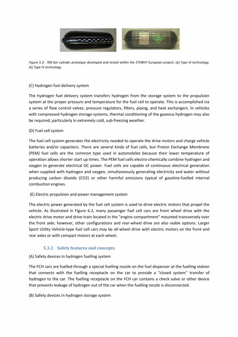
Figure 5.3: 700 bar cylinder prototype developed and tested within the STORHY European project: (a) Type III technology,
(b) Type IV technology
(C) Hydrogen fuel delivery system
The hydrogen fuel delivery system transfers hydrogen from the storage system to the propulsion
system at the proper pressure and temperature for the fuel cell to operate. This is accomplished via
a series of flow control valves, pressure regulators, filters, piping, and heat exchangers. In vehicles
with compressed hydrogen storage systems, thermal conditioning of the gaseous hydrogen may also
be required, particularly in extremely cold, sub-freezing weather.
(D) Fuel cell system
The fuel cell system generates the electricity needed to operate the drive motors and charge vehicle
batteries and/or capacitors. There are several kinds of fuel cells, but Proton Exchange Membrane
(PEM) fuel cells are the common type used in automobiles because their lower temperature of
operation allows shorter start up times. The PEM fuel cells electro-chemically combine hydrogen and
oxygen to generate electrical DC power. Fuel cells are capable of continuous electrical generation
when supplied with hydrogen and oxygen, simultaneously generating electricity and water without
producing carbon dioxide (CO2) or other harmful emissions typical of gasoline-fuelled internal
combustion engines.
(E) Electric propulsion and power management system
The electric power generated by the fuel cell system is used to drive electric motors that propel the
vehicle. As illustrated in Figure 6.2, many passenger fuel cell cars are front wheel drive with the
electric drive motor and drive-train located in the "engine compartment" mounted transversely over
the front axle; however, other configurations and rear-wheel drive are also viable options. Larger
Sport Utility Vehicle-type fuel cell cars may be all-wheel drive with electric motors on the front and
rear axles or with compact motors at each wheel.
5.3.2. Safety features and concepts
(A) Safety devices in hydrogen fuelling system
The FCH cars are fuelled through a special fuelling nozzle on the fuel dispenser at the fuelling station
that connects with the fuelling receptacle on the car to provide a "closed system" transfer of
hydrogen to the car. The fuelling receptacle on the FCH car contains a check valve or other device
that prevents leakage of hydrogen out of the car when the fuelling nozzle is disconnected.
(B) Safety devices in hydrogen storage system
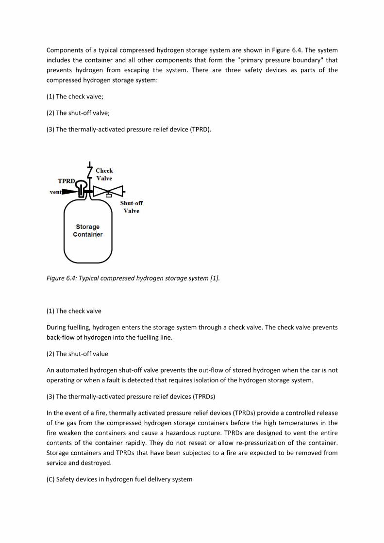
Components of a typical compressed hydrogen storage system are shown in Figure 6.4. The system
includes the container and all other components that form the "primary pressure boundary" that
prevents hydrogen from escaping the system. There are three safety devices as parts of the
compressed hydrogen storage system:
(1) The check valve;
(2) The shut-off valve;
(3) The thermally-activated pressure relief device (TPRD).
Figure 6.4: Typical compressed hydrogen storage system [1].
(1) The check valve
During fuelling, hydrogen enters the storage system through a check valve. The check valve prevents
back-flow of hydrogen into the fuelling line.
(2) The shut-off value
An automated hydrogen shut-off valve prevents the out-flow of stored hydrogen when the car is not
operating or when a fault is detected that requires isolation of the hydrogen storage system.
(3) The thermally-activated pressure relief devices (TPRDs)
In the event of a fire, thermally activated pressure relief devices (TPRDs) provide a controlled release
of the gas from the compressed hydrogen storage containers before the high temperatures in the
fire weaken the containers and cause a hazardous rupture. TPRDs are designed to vent the entire
contents of the container rapidly. They do not reseat or allow re-pressurization of the container.
Storage containers and TPRDs that have been subjected to a fire are expected to be removed from
service and destroyed.
(C) Safety devices in hydrogen fuel delivery system

The fuel delivery system shall reduce the pressure from levels in the hydrogen storage system to
values required by the fuel cell system. In the case of a 70 MPa NWP compressed hydrogen storage
system, for example, the pressure may have to be reduced from as high as 87.5 MPa to less than 1
MPa at the inlet of the fuel cell system. This may require multiple stages of pressure regulation to
achieve accurate and stable control and over-pressure protection of down-stream equipment in the
event that a pressure regulator fails. Over-pressure protection of the fuel delivery system may be
accomplished by venting excess hydrogen gas through pressure relief valves or by isolating the
hydrogen gas supply (by closing the shutoff valve in the hydrogen storage system) when a down-
stream over-pressure condition is detected.
5.4. FC Buses
5.4.1. Description
FC buses use the same technology as FCH cars described in the section 6.1. Hydrogen, which is
stored in tanks (usually located on the roof of the bus) mixes with oxygen from the air creating
electricity to drive the electric motors [2]. The main advantages of FC buses compared to the
conventional ones are reduced pollution; lower concentration of greenhouse gases; increased
energy efficiency and a quieter operation [2].
There is a range of European projects associated with a hydrogen-based transport. For example,
Clean Energy Partnership (CEP) (http://www.cleanenergypartnership.de) is the project that aims to
test and to demonstrate the use of FCH technologies in transport applications. CEP, established in
2002, is an international cooperation of 18 partners including leading car manufacturers such as
BMW Group, Honda, Daimler, Ford, Hyundai, GM/Opel, Toyota and Volkswagen. In 2011 CEP moved
to its third phase ‘Market preparation’. Another project is HyFleet: Cute (http://www.global-
hydrogen-bus-platform.com/Home), which seeks to develop and operate the world’s largest fleet of
FC buses. There are between 40 and 45 FC and Internal Combustion Engine (ICE) buses in operation
around the world, most of which are in regular public service [3]. These buses have been successful
in providing valuable data to developers and operators as they are operated under harsh conditions,
through uninterrupted operation and extreme climatic conditions. Another important aspect of this
project has been to familiarize the public with this new technology and to thereby gain public
acceptance of its introduction [3]. London now has a fleet of 8 FC buses running on route RV1
between Covent Garden and Tower Gateway (Figure 6.5).
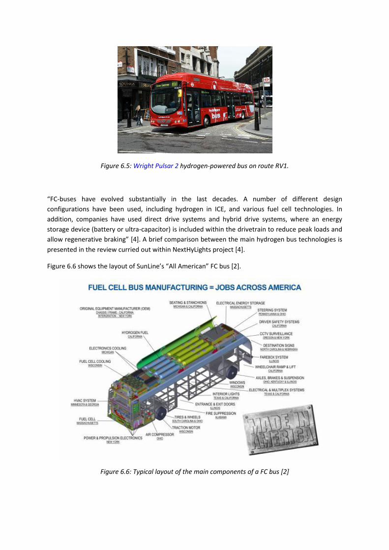
Figure 6.5: Wright Pulsar 2 hydrogen-powered bus on route RV1.
“FC-buses have evolved substantially in the last decades. A number of different design
configurations have been used, including hydrogen in ICE, and various fuel cell technologies. In
addition, companies have used direct drive systems and hybrid drive systems, where an energy
storage device (battery or ultra-capacitor) is included within the drivetrain to reduce peak loads and
allow regenerative braking” [4]. A brief comparison between the main hydrogen bus technologies is
presented in the review curried out within NextHyLights project [4].
Figure 6.6 shows the layout of SunLine’s “All American” FC bus [2].
Figure 6.6: Typical layout of the main components of a FC bus [2]
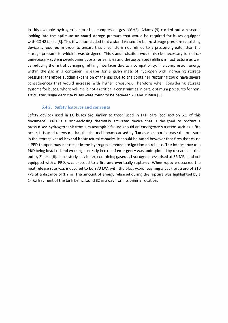
In this example hydrogen is stored as compressed gas (CGH2). Adams [5] carried out a research
looking into the optimum on-board storage pressure that would be required for buses equipped
with CGH2 tanks [5]. This it was concluded that a standardised on-board storage pressure restricting
device is required in order to ensure that a vehicle is not refilled to a pressure greater than the
storage pressure to which it was designed. This standardisation would also be necessary to reduce
unnecessary system development costs for vehicles and the associated refilling infrastructure as well
as reducing the risk of damaging refilling interfaces due to incompatibility. The compression energy
within the gas in a container increases for a given mass of hydrogen with increasing storage
pressure; therefore sudden expansion of the gas due to the container rupturing could have severe
consequences that would increase with higher pressures. Therefore when considering storage
systems for buses, where volume is not as critical a constraint as in cars, optimum pressures for non-
articulated single deck city buses were found to be between 20 and 35MPa [5].
5.4.2. Safety features and concepts
Safety devices used in FC buses are similar to those used in FCH cars (see section 6.1 of this
document). PRD is a non-reclosing thermally activated device that is designed to protect a
pressurised hydrogen tank from a catastrophic failure should an emergency situation such as a fire
occur. It is used to ensure that the thermal impact caused by flames does not increase the pressure
in the storage vessel beyond its structural capacity. It should be noted however that fires that cause
a PRD to open may not result in the hydrogen’s immediate ignition on release. The importance of a
PRD being installed and working correctly in case of emergency was underpinned by research carried
out by Zalosh [6]. In his study a cylinder, containing gaseous hydrogen pressurised at 35 MPa and not
equipped with a PRD, was exposed to a fire and eventually ruptured. When rupture occurred the
heat release rate was measured to be 370 kW, with the blast-wave reaching a peak pressure of 310
kPa at a distance of 1.9 m. The amount of energy released during the rupture was highlighted by a
14 kg fragment of the tank being found 82 m away from its original location.
5.5. Forklift
5.5.1. Description
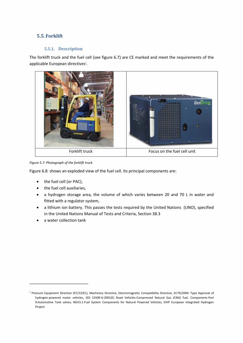
The forklift truck and the fuel cell (see figure 6.7) are CE marked and meet the requirements of the
applicable European directives2.
Forklift truck Focus on the fuel cell unit
Figure 5.7: Photograph of the forklift truck
Figure 6.8 shows an exploded view of the fuel cell. Its principal components are:
the fuel cell (or PAC),
the fuel cell auxiliaries,
a hydrogen storage area, the volume of which varies between 20 and 70 L in water and
fitted with a regulator system,
a lithium ion battery. This passes the tests required by the United Nations (UNO), specified
in the United Nations Manual of Tests and Criteria, Section 38.3
a water collection tank
2 Pressure Equipment Directive (97/23/EC), Machinery Directive, Electromagnetic Compatibility Directive, EC79/2009: Type Approval of
hydrogen-powered motor vehicles, ISO 15500-6-2001(E) Road Vehicles-Compressed Natural Gas (CNG) fuel, Components-Part
9:Automotive Tank valves, NGV3.1-Fuel System Components for Natural Powered Vehicles, EIHP European Integrated Hydrogen
Project

Figure 5.8: Exploded view of the fuel cell
5.5.2. Safety features and concepts
From a safety point of view, the hydrogen storage is protected by a thermal fuse (F1 in Figure 6-1)
situated between the forklift's isolation valve (V6) and the cylinder itself. This fuse opens at 109°C
and allows the rapid release of pressurised hydrogen. There is also a non-return valve on the filling
port to prevent gas present in the storage from escaping. Also, all the components of the fuel cell
are built into a cast iron casing, itself protected by a cover. There are two advantages to this cast
iron casing: it provides strength against external mechanical attack and allows the flow received to
be evened out in the event of an external thermal attack.
Building
Battery
Hydrogen
storage
Cover
Ballast
6. Hydrogen refueling stations
6.1. Description
6.1.1. Operating principle
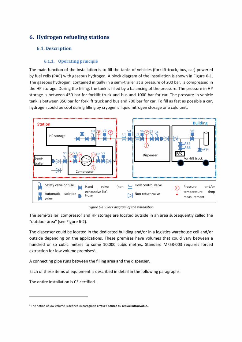
The main function of the installation is to fill the tanks of vehicles (forklift truck, bus, car) powered
by fuel cells (PAC) with gaseous hydrogen. A block diagram of the installation is shown in Figure 6-1.
The gaseous hydrogen, contained initially in a semi-trailer at a pressure of 200 bar, is compressed in
the HP storage. During the filling, the tank is filled by a balancing of the pressure. The pressure in HP
storage is between 450 bar for forklift truck and bus and 1000 bar for car. The pressure in vehicle
tank is between 350 bar for forklift truck and bus and 700 bar for car. To fill as fast as possible a car,
hydrogen could be cool during filling by cryogenic liquid nitrogen storage or a cold unit.
Figure 6-1: Block diagram of the installation
The semi-trailer, compressor and HP storage are located outside in an area subsequently called the
"outdoor area" (see Figure 6-2).
The dispenser could be located in the dedicated building and/or in a logistics warehouse cell and/or
outside depending on the applications. These premises have volumes that could vary between a
hundred or so cubic metres to some 10,000 cubic metres. Standard MF58-003 requires forced
extraction for low volume premises3.
A connecting pipe runs between the filling area and the dispenser.
Each of these items of equipment is described in detail in the following paragraphs.
The entire installation is CE certified.
3 The notion of low volume is defined in paragraph Erreur ! Source du renvoi introuvable..
Building Station
HP storage
PAC Dispenser Forklift truck Semi-
trailer
Compressor
Flow control valve Safety valve or fuse Pressure and/or
temperature drop
measurement
Hand valve (non-
exhaustive list) Non-return valve Automatic isolation
valve Hose
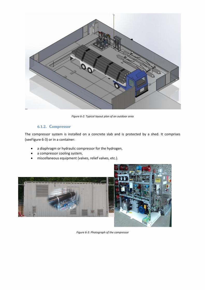
Figure 6-2: Typical layout plan of an outdoor area
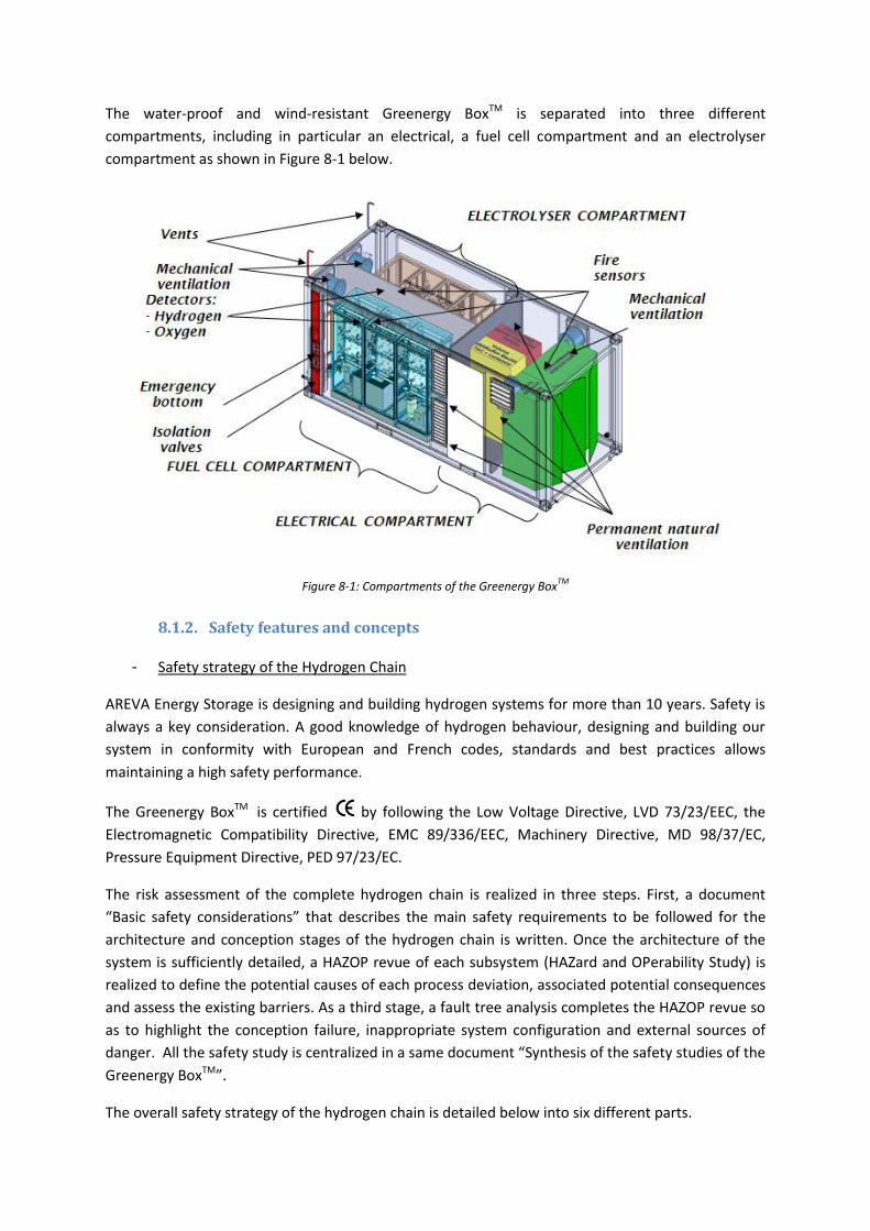
6.1.2. Compressor
The compressor system is installed on a concrete slab and is protected by a shed. It comprises
(seeFigure 6-3) or in a container:
a diaphragm or hydraulic compressor for the hydrogen,
a compressor cooling system,
miscellaneous equipment (valves, relief valves, etc.).
Figure 6-3: Photograph of the compressor

6.1.3. HP Storage (or "buffer")
The HP storage is a buffer capacity and meets the Pressurised Equipment Directive (DESP) (Figure
6-4).
Its total volume varies between 1,000 and 3,000 L in water. It may be designed from several storages
whose unit volume varies between 50 and 1,500 L. The pressure in HP storage is between 450 bar
for forklift truck and bus and 1000 bar for car. The storage is protected by a relief valve (S3). The
discharge from this relief valve is evacuated through the same vent stack as that used for the
compressor system (see previous paragraph).
Figure 6-4: Image of the HP storage
6.1.4. Connecting pipework
This pipework connects the HP storage to the dispenser. Depending on the site concerned, its total
length can vary between several tens and several hundreds of metres. So far as is possible, an
outdoor routing is preferable, in order to avoid the risk of a leak indoors. Parts crossing access roads
are contained in a channel or supported on a gantry or buried and exposed parts are protected
(possibly physical protection on vertical sections, passing through walls or on a roof). Pipework
enters the building at the last possible moment for connection to the dispenser.
The characteristics of the pipework are:
Material: compatible with the use of hydrogen (example: 316L stainless steel).
Outside diameter: less than 1” depending on the length of the pipework.
6.1.5. The dispenser
The dispenser may be installed in one of three different places:
in a storage cell
in a dedicated room,
outside
The dispenser comprises (see Figure 6-5):
a mast, itself equipped with;
o a hose fitted with an anti-tear-out system and connected to a filling gun
o a cabinet containing the pipework connection and the system of valves
station-vehicule communication and vehicule earthing cable (when it is needed),

a pipe for draining water from the truck's water tank
a remote interface allowing the operator to remotely control the filling of the forklift.
Figure 6-5: Configuration example for a dispenser
6.1.6. Description of the different operating modes
The installation has three distinct operating modes:
the HP storage filling phase
the forklift filling phase
the forklift filling phase in impaired mode
Each of these situations is illustrated very diagrammatically in
Figure 6-6. After each filling the connection pipework is isolated from the outside by closing valves
V3 and V4. The dispenser is then de-pressurised by opening vent valve E1 and isolated by valve V5.
A daily test is done in the following stages.
o Isolation valves V3 and V4 opened (while valves V2 and V5 are kept closed),
o Waiting for the pressure to balance upstream and downstream of V3,
o Once that pressure is balanced, valve V3 is closed,
o Monitoring of pressure changes downstream of V3. This monitoring time is defined
depending on the acceptable rate leakage from the installation.
Any leak noted during the daily test results in valves V3, V4 and V5 being closed, vent E1 being
opened and the station being closed until it has been dealt with by the maintenance department.
This test is automatic. It is recommended that it is carried out before use.
A leak tightness test before every filling operation. This is done according to the following
steps:
o Vent valve E1 is closed, valves V3, V4 and V5 are opened.
Hydrogen mast
Interface
Forklift truck
location
Protective
barriers
Safety area Safety area

o Valve V5 closed and comparison of the pressure measured at the dispenser with
that at the exit from the HP storage.
o Monitoring of pressure changes measured in the dispenser. This monitoring time is
defined depending on the acceptable rate leakage from the installation.
Any leak noted during the daily test results in valves V3, V4 and V5 being closed, vent E1 being
opened and the station being closed until it has been dealt with by the maintenance department.
This test is automatic.
A leak tightness test during filling. It consists of controlling the changes in the pressure
measured during filling. This test is automatic.
Figure 6-6: Presentation of the installation's three different operating modes
6.2. Safety features and concepts
6.2.1. Outdoor area
The "outdoor area" is identified, marked out, physically protected and has controlled access. It
complies with "industrial" hydrogen installation rules. Among the main rules, we should cite access
not possible to unauthorised personnel, compliance with a minimum distance from a building, or
alternatively the presence of an REI120 wall.
From a safety point of view, the hydrogen compressor is equipped with two automatic isolation
valves at the intake and exit (V1 and V2 in Figure 6-1), a safety relief valve (S2) and a non-return
Semi-
trailer
The HP storage filling
phase
.
The forklift filling phase
Station
Building
Building
Station
HP storage
HP storage
Compressor
Compressor
Dispenser
Dispenser
Semi-
trailer
Forklift truck
Forklift truck
PAC
PAC
The forklift filling phase
in impaired mode.
Station Building
HP storage
Compressor
Dispenser
Semi-
trailer
Forklift truck
PAC

valve. Discharges from relief valves are collected and evacuated through a vent stack which is sized
according to the maximum permitted flow rate, the noise on exiting the vent; the heat flow caused
by the hydrogen flame and expected overpressures in the event of the discharged hydrogen cloud
igniting. Also, the compression system includes a retention tank, sized according to the quantity of
oil used.
6.2.2. Connecting pipework
The pipework includes an automatic isolation valve (V3 in Figure 6-1), normally closed and located in
the outdoor area.
6.2.3. Dispenser
The items contributing to safety are as follows:
The dispenser is located away from roadways. If it is needed, protective barriers are put in
place around it to prevent any collision with a vehicle approaching to be filled or with
another one manoeuvring in the area. The dispenser is also on a raised platform.
Combustible things are kept at least 4 m away from the dispenser. Markings on the floor
make the perimeter clearly visible.
The vehicule's speed is limited. An area is marked on the floor to indicate the position of the
vehicle during filling.
When the operator handles the hose (connection to or disconnection from the vehicule), the
hose is no longer under pressure.
The filling control interface is 2 m away from the hydrogen mast (ATEX zoning).
An anti-tear-out system is fitted to the hose. If the hose is torn out, the device quickly closes
two valves to isolate the leak on the station side and the truck side. It is therefore a weak
point in the line.
The dispenser is fitted with a regulator/ flow limiter (L2 in Figure 6-1), with a normally closed
isolation valve (V5), with a safety reducing valve (S4) and a normally open vent valve (E1).
During normal operation of the installation, flow limiter L2 is used to regulate the
downstream flow rate, such that a rise in pressure in the vehicle’s storage is limited. In the
event of an accidental rupture occurring downstream of this item, it is expected that it will
limit the rate of leakage. Discharges from S4 and E1 are collected in a second vent stack
which is sized according to the maximum permitted flow rate, the noise on exiting the vent,
the heat flow caused by the hydrogen flame and expected overpressures in the event of the
released hydrogen cloud igniting. It is situated on the building.
If the dispenser is located in a building, a naked flame detector (UV/IR sensor appropriate to
the radiation characteristics of a hydrogen flame) could be positioned above the dispenser.
Hydrogen detection is installed in the dispenser at the top of the mast. During the filling
stages, a concentration greater than 25% of the LEL or the detection of a flame will result in
all isolation valves (V3, V4 and V5) closing and vent valve (E1) opening. Other than during the
filling phase, the isolation valves are closed and the vent valve is open.
If the dispenser is located in a building of relatively modest, hydrogen detection is also
installed in the upper part of the building (ambient detection). In actual fact, the low volume
inside the building may not allow sufficient dilution of the hydrogen discharge to prevent it

from forming an explosive atmosphere. An air extractor is also installed, as required by
standard M58-003.
7. FC stationary applications
7.1. Combined production of Heat and Power (CHP) system
This application is exactly the same that Hydrogen based energy storage see section 8.1
7.2. Stationary back-up power generation
7.2.1. Principle and functioning of the fuel cell
The fuel cell is an electrochemical generator which produces electricity, heat and water (pure), from
a fuel (hydrogen) and a combustive (oxygen which can be pure or resulting from the ambient air).
Several technologies of fuel cell exist, AREVA Stockage d’Energie focuses exclusively on fuel Cells of
the PEM type (Proton Exchange Membrane), operating with hydrogen and oxygen gases. With these
gases, fuel cell has a better efficiency and to be independent of the ambient air (anaerobic
operation), which allows operation in a hostile or vitiated environment, even confined.
• The principle of operation of a fuel cell of the PEM type is the following:
- At the anode, the hydrogen H2 molecules are dissociated in H+ protons and electrons e- under the
effect of a catalyst: H2 → 2H+ + 2 e-,
These protons are led to cathode through the membranes and the electrons pass through the
external electrical circuit.
- At the cathode, the oxygen O2 molecules are recombined with the protons and the electrons to
form water: ½ O2 + 2H+ + 2e- → H2O.
Figure 7-1: Schematic principle of fuel cell functioning

In a practical way, the electrodes (anode and cathode) and the membrane are associated to form a
Membrane Electrode Assembly called MEA.
It should be noted that water is in vapor and liquid forms, and that a part is transferred to the anode
(hydrogen side) by electroosmosis.
This reaction generates a differential of terminal voltage at the electrochemical cell, function of the
generated current (about 0.7 V with the rated current). A stacking of fuel cell (called stack) allows
obtaining the desired power.
Figure 7-2: Illustration of a MEA
7.2.2. Example of FC stationary application: Backup system connected to a
datacenter
The main objective of such a technology is to provide instantaneous power in time in case of
blackout

Figure 7-3: Back up system on AREVA Stockage d’Energie-Aix en Provence
- Overview of the process
- Technical specifications
- Main advantages
High reliability and fast startup
Scalable autonomy only depending on gas storage volume
Low maintenance
Clean and silent
- USERS
Telecom, Datacenters
Hospitals, Military
Industries

Luxury hotels
- Reference project: IP Project
Figure 7-4: Fuel cell backup power coupled to the IP Energy data center
- Key facts & figures
Market segment: Backup Power
Customer: IP Energy
Location: Aix-en-Provence, France
Power supply: 30 kW
Schedule: Installed in 2008
- Results of the IP Energy project:
30 kVA backup power system installed in 2008, 1st containerized solution
Internal gas storage allowing a 4-hour operating capacity
3-year experience feedback as backup power supply to AREVA Energy Storage’s test
benches, until 2011
In late 2011, it provides backup power to a modular and containerized data center
7.2.3. Safety features and concepts
- Gas Venting
The fuel cell system has two separated vent lines, one for oxygen and one for hydrogen, that
discharges the gas on the roof of the container at a separation distance to avoid mixing of oxygen
and hydrogen during discharge. After a discharge, a residual amount of hydrogen subsists within the
system.
- H2 detection
The process compartment is equipped with two hydrogen sensors that triggers an emergency stop if
the hydrogen concentration is above 0.4% H2 (vol.) in the containers.

If an abnormal hydrogen concentration is detected, a safety stop is triggered and the following
actions will take place:
o Stop of the process of the system
o Activation of the mechanical ventilations
o Insulation of gas storages (closing of the solenoid valves)
Detection H2 is insured permanently even if the system is on standby. In the event of loss of
detection, the system triggers a safety stop.
- Fire detection
The container is equipped with fire detector sets fire which can provoke an emergency stop of the
system:
o Stop of the process of the system
o Insulation of gas storages (closing of the solenoid valves)
o Cutting off ventilations
- Prevention of hydrogen accumulation and ATEX formation
Hazardous explosive atmospheres resulting from anticipated hydrogen leaks or releases shall be
prevented in the Fuel Cell enclosure.
Passive prevention methods include but are not limited to:
- use of joints that are permanently secured and so constructed so that they limit the maximum release rate to a predictable value;
- natural ventilation.
Active prevention methods include but are not limited to:
- active ventilation; - a flammable gas detection system; - other means of leak detection (e.g. through pressure measurements relative to control
settings).
- To reduce ignition sources
The inside of the container where hydrogen may leak or diffuse into is not classified since safety
barriers ensure no dangerous hydrogen ATEX at the leaking point or by accumulation. Nonetheless,
all equipment installed just below the container ceiling and susceptible ignite a flammable hydrogen-
air mixture is certified for ATEX zone 2. In particular, it concerns the fire, hydrogen, sensors and the
ventilation system.
Besides, the electrical compartment is systematically separated from the process compartment.
- Prevention of the risk related to the use of oxygen

Oxygen is not flammable in the air but it maintains combustion (it constitutes the combustive). An
oxygen leak can be at the origin of a fire hazard. The fire risk is increased when the atmosphere is
enriched out of oxygen:
- At 23%; combustion is accelerated.
- At 30%; combustion is intense.
- At 50%; combustion is instantaneous.
Any contact must be avoided between oxygen and the organic matters because of the fire risk.
General measures of risk prevention are taken with the design and in exploitation:
Choice of the materials (degreased stainless), protected pipes and without abrupt
elbows, tight connections and as much as possible welded
Limitation of the oxygen flows according to the pressure
Protection of the oxygen lines by filters in order to trap dust that is likely to ignite
Natural and forced ventilation in the process compartment
Reduction of lengths of the pipe under high pressure, sufficient separation of the
pipes with the electric components
Regrouping of the bodies containing oxygen in a delimited zone (compartment)
Respect of the procedures of control and maintenance (periodic tests) of the
facilities defined in addition

8. Decentralized hydrogen production
8.1. Hydrogen-based energy storage system (Greenergy Box)
8.1.1. Description
The Greenergy BoxTM is a containerized hydrogen chain comprising an electrolyser, a fuel cell, a
water and heat management, and electrical converter systems coupled with a hydrogen and oxygen
storages installed aside of the container. The Greenergy BoxTM is an integrated modular system that
can offer a power from 50 to 500 kW with a storage capacity from 0.2 to 2 MWh. Several systems
can be coupled to increase the power and the energetic capacity. Coupled with RES, such a solution
allows not only ensuring a partial building autonomy from 45 to 85 % but also providing the function
of backup system for few hours at high power.
The photovoltaic panels provide electricity to the electrical network and the surplus is used by the
electrolyser to generate gaseous hydrogen and oxygen. Once produced, gaseous hydrogen and
oxygen are stored within separated tanks installed aside of the Greenergy BoxTM. It is thanks to the
fuel cell system that the stored hydrogen and oxygen can be used to produce electricity to ensure
partial energetic autonomy of the buildings as well as the backup system in case of power cut. The
Greenergy BoxTM manages itself the electricity received by the photovoltaic panels to electrolyze
water or to provide electricity to the network. Furthermore, heat, which is also produced by the
system during both electrolysis and fuel cell processes, is also managed and valorised for the
adjacent buildings.
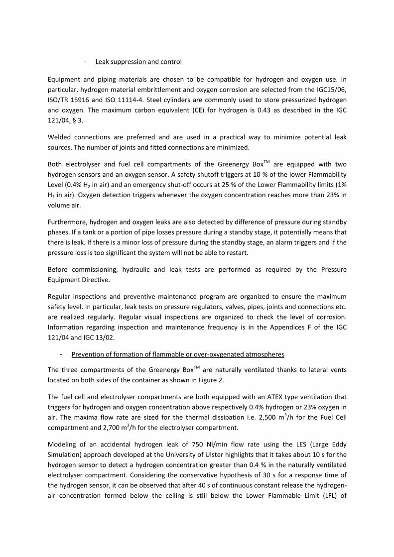
The water-proof and wind-resistant Greenergy BoxTM is separated into three different
compartments, including in particular an electrical, a fuel cell compartment and an electrolyser
compartment as shown in Figure 8-1 below.
Figure 8-1: Compartments of the Greenergy BoxTM
8.1.2. Safety features and concepts
- Safety strategy of the Hydrogen Chain
AREVA Energy Storage is designing and building hydrogen systems for more than 10 years. Safety is
always a key consideration. A good knowledge of hydrogen behaviour, designing and building our
system in conformity with European and French codes, standards and best practices allows
maintaining a high safety performance.
The Greenergy BoxTM is certified by following the Low Voltage Directive, LVD 73/23/EEC, the
Electromagnetic Compatibility Directive, EMC 89/336/EEC, Machinery Directive, MD 98/37/EC,
Pressure Equipment Directive, PED 97/23/EC.
The risk assessment of the complete hydrogen chain is realized in three steps. First, a document
“Basic safety considerations” that describes the main safety requirements to be followed for the
architecture and conception stages of the hydrogen chain is written. Once the architecture of the
system is sufficiently detailed, a HAZOP revue of each subsystem (HAZard and OPerability Study) is
realized to define the potential causes of each process deviation, associated potential consequences
and assess the existing barriers. As a third stage, a fault tree analysis completes the HAZOP revue so
as to highlight the conception failure, inappropriate system configuration and external sources of
danger. All the safety study is centralized in a same document “Synthesis of the safety studies of the
Greenergy BoxTM”.
The overall safety strategy of the hydrogen chain is detailed below into six different parts.
- Leak suppression and control Equipment and piping materials are chosen to be compatible for hydrogen and oxygen use. In
particular, hydrogen material embrittlement and oxygen corrosion are selected from the IGC15/06,
ISO/TR 15916 and ISO 11114-4. Steel cylinders are commonly used to store pressurized hydrogen
and oxygen. The maximum carbon equivalent (CE) for hydrogen is 0.43 as described in the IGC
121/04, § 3.
Welded connections are preferred and are used in a practical way to minimize potential leak
sources. The number of joints and fitted connections are minimized.
Both electrolyser and fuel cell compartments of the Greenergy BoxTM are equipped with two
hydrogen sensors and an oxygen sensor. A safety shutoff triggers at 10 % of the lower Flammability
Level (0.4% H2 in air) and an emergency shut-off occurs at 25 % of the Lower Flammability limits (1%
H2 in air). Oxygen detection triggers whenever the oxygen concentration reaches more than 23% in
volume air.
Furthermore, hydrogen and oxygen leaks are also detected by difference of pressure during standby
phases. If a tank or a portion of pipe losses pressure during a standby stage, it potentially means that
there is leak. If there is a minor loss of pressure during the standby stage, an alarm triggers and if the
pressure loss is too significant the system will not be able to restart.
Before commissioning, hydraulic and leak tests are performed as required by the Pressure
Equipment Directive.
Regular inspections and preventive maintenance program are organized to ensure the maximum
safety level. In particular, leak tests on pressure regulators, valves, pipes, joints and connections etc.
are realized regularly. Regular visual inspections are organized to check the level of corrosion.
Information regarding inspection and maintenance frequency is in the Appendices F of the IGC
121/04 and IGC 13/02.
- Prevention of formation of flammable or over-oxygenated atmospheres
The three compartments of the Greenergy BoxTM are naturally ventilated thanks to lateral vents
located on both sides of the container as shown in Figure 2.
The fuel cell and electrolyser compartments are both equipped with an ATEX type ventilation that
triggers for hydrogen and oxygen concentration above respectively 0.4% hydrogen or 23% oxygen in
air. The maxima flow rate are sized for the thermal dissipation i.e. 2,500 m3/h for the Fuel Cell
compartment and 2,700 m3/h for the electrolyser compartment.
Modeling of an accidental hydrogen leak of 750 Nl/min flow rate using the LES (Large Eddy
Simulation) approach developed at the University of Ulster highlights that it takes about 10 s for the
hydrogen sensor to detect a hydrogen concentration greater than 0.4 % in the naturally ventilated
electrolyser compartment. Considering the conservative hypothesis of 30 s for a response time of
the hydrogen sensor, it can be observed that after 40 s of continuous constant release the hydrogen-
air concentration formed below the ceiling is still below the Lower Flammable Limit (LFL) of

hydrogen in air i.e. 4 % by air volume. From this moment, the hydrogen sensor sends a signal to the
control command that triggers the air intake fan to its maximal speed. It can be observed that the
hydrogen air cloud is entirely diluted in less than 2 s.
- Suppression/Reducing of ignition sources The inside of the Greenergy BoxTM where hydrogen may leak or diffuse into is not classified since
safety barriers ensure no dangerous hydrogen ATEX at the leaking point or by accumulation.
Nonetheless, all equipment installed just below the container ceiling and susceptible ignite a
flammable hydrogen-air mixture is certified for ATEX zone 2. In particular, it concerns the fire,
hydrogen, oxygen sensors and the ventilation system.
The Greenergy BoxTM and reservoirs are earthed and bonded to give protection against the hazards
of stray electrical currents and static electricity.
- Protection against overpressures
Each reservoir and piping lines from the Greenergy BoxTM to the storage tanks are equipped with a
pressure relief valve. The tare pressure of the pressure relief valve is set so that the PRV actuates
when the pressure within the reservoir reaches 1.15 of the maximal operating pressure.
The storage tank vents are mounted vertically at a minimum high of 3 m. They are equipped with a
hat for which the weight is calibrated to lift under pressure in order to avoid the introduction of
water within the vent.
The Greenergy BoxTM is equipped with two distinct hydrogen and oxygen vents located at a
minimum height of 1 m above the roof of the container and well separated to avoid oxygen-enriched
hydrogen-air mixture. Each distinct venting line is common to the electrolyser and the fuel cell and
allows the depressurization of the totality of the system in less than 2 minutes in case of emergency
shut-down.
- Emergency and safety shutdown
The control command that is used for piloting automatically the system is also used to trigger the
safety functions. About 70 safety functions are recorded into the control command to detect any
process deviation or gaseous leak or fire within the system. Depending on the amplitude of the
deviation compared to the safety threshold of the parameter, an emergency or and safety shutdown
is triggered and is followed by power shutdown, system depressurization, inerting and ventilation
activation (except for fires).
The main safety functions i.e. H2, O2 and fire detections, emergency shutdown bottom and watchdog
of the control command are realized by logic cable and respect a SIL 1 level (Safety Integrity Level).
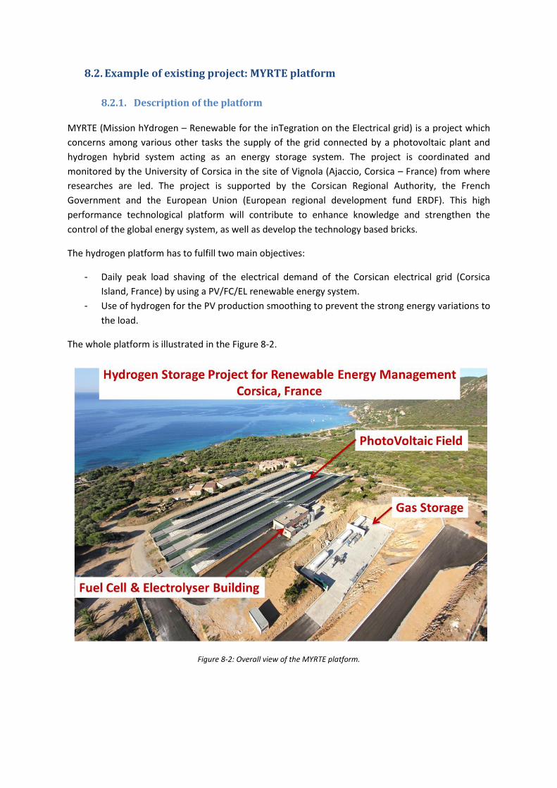
8.2. Example of existing project: MYRTE platform
8.2.1. Description of the platform
MYRTE (Mission hYdrogen – Renewable for the inTegration on the Electrical grid) is a project which
concerns among various other tasks the supply of the grid connected by a photovoltaic plant and
hydrogen hybrid system acting as an energy storage system. The project is coordinated and
monitored by the University of Corsica in the site of Vignola (Ajaccio, Corsica – France) from where
researches are led. The project is supported by the Corsican Regional Authority, the French
Government and the European Union (European regional development fund ERDF). This high
performance technological platform will contribute to enhance knowledge and strengthen the
control of the global energy system, as well as develop the technology based bricks.
The hydrogen platform has to fulfill two main objectives:
- Daily peak load shaving of the electrical demand of the Corsican electrical grid (Corsica
Island, France) by using a PV/FC/EL renewable energy system.
- Use of hydrogen for the PV production smoothing to prevent the strong energy variations to
the load.
The whole platform is illustrated in the Figure 8-2.
Figure 8-2: Overall view of the MYRTE platform.

The overall functioning principles is described the Figure below. The photovoltaic panels provide electricity to the electrical network and the surplus is used by the electrolyser to generate gaseous hydrogen and oxygen, as shown in Figure 1. Once produced, gaseous hydrogen and oxygen are stored within separated reservoirs. It is thanks to the fuel cell system that the stored hydrogen and oxygen can be used to inject electricity to electrical grid network. The overall chain manages itself the electricity received by the photovoltaic panels to electrolyze water or to provide electricity to the network. Furthermore, heat, which is also produced by the system during both electrolysis and hydrolysis processes, is also managed and valorized.
The platform is composed of several sub-systems that include in particular:
A photovoltaic farm that aims at providing electrical energy to the electrical network but
also to the electrolyser;
A hydrogen building that includes:
o an electrolyser that generates gaseous hydrogen and oxygen using the electricity
surplus;
o A H2/O2 fuel cell that provides electricity using the gas stored in the reservoirs to
deliver electricity to the network;
o The electric management that ensures the conditioning of the electrical energy to
provide the electrical network
o The control command room to pilot the whole system;
-
Electricity
network
Corse
Photovoltaic
panels
560 kWc
+
Thermal storage
Electricity
Gas

Figure 8-3: Hydrogen building containing the fuel cell System and the electrolyser.
Hydrogen and oxygen storages;
Figure 8-4: Storage zone.
Heating managing system that ensures the storage and the management of the heat
produced by the system;
The MYRTE Project is organised in two main phases. For the first phase of the project that was
launched in June 2011, a 100 kW fuel cell of and a 10 Nm3/h (50 kW) electrolyser were installed in
the Hydrogen building. The net electrical energy stored is equivalent to 1.75 MWh using two
hydrogen reservoirs of 28 geometrical cubic meters each.
For the second phase of the project that was launched in February 2014, the discharge power was
extended to 150 kW by adding a fuel cell of 50 kW and the charge power was extended to 125 kW by
adding a 15 Nm3/h PEM electrolyser. The electrolyser and FC systems were installed into an
integrated solution i.e. the Greenergy BoxTM.
Charge power:
50 kW
Discharge power:
100 kW
Storage capacity:
1.75 MWh

8.2.2. Example of intervention map for Fire and Rescue services
Phase 2:
Charge power of 125 kW Discharge power of 150 kW


8.3. JANUS
8.3.1. Description of the project
The city of La Croix Valmer, located in the Golf of Saint Tropez, faces the problematic increase of population by a factor 10 in summer. Furthermore, the city of La Croix Valmer is often exposed to repeated power cut on account of the end line location on the electrical network. In this context, the city of La Croix Valmer has fixed the objective to be more electrically independent from the network.
JANUS is the name given to the project which the aim is to install a hydrogen-based energy storage
system and production i.e. the Greenergy BoxTM the Kid Leisure Centre at La Croix-Valmer (Var,
department in south of France).
Figure 8-5: Pictures of the Kid Leisure Centre at La Croix-Valmer
The purpose of the system is to act like a storage system of energy. Indeed, it stores energy
(resulting from production by photovoltaic panels) and restores it at the convenient periods in
electric and thermal form to feed the Childhood Pole of the commune of La Croix-Valmer.
In order to ensure this, energy resulting from the photovoltaic panels installed on the building, is
stored in a module Greenergy Box in Hydrogen form and Oxygen form by means of an electrolyser.
This energy is then restored via the fuel cell of the module Greenergy Box™.
The entire system enables the building to increase its autonomy in energy as well as to adapt the
energy production with the periods of consumption. In the long term, this kind of installation must
also stabilize the local area electrical network.
Furthermore, heat, which is also produced by the system during both electrolysis and hydrolysis
processes, is also managed and valorised for the adjacent buildings.
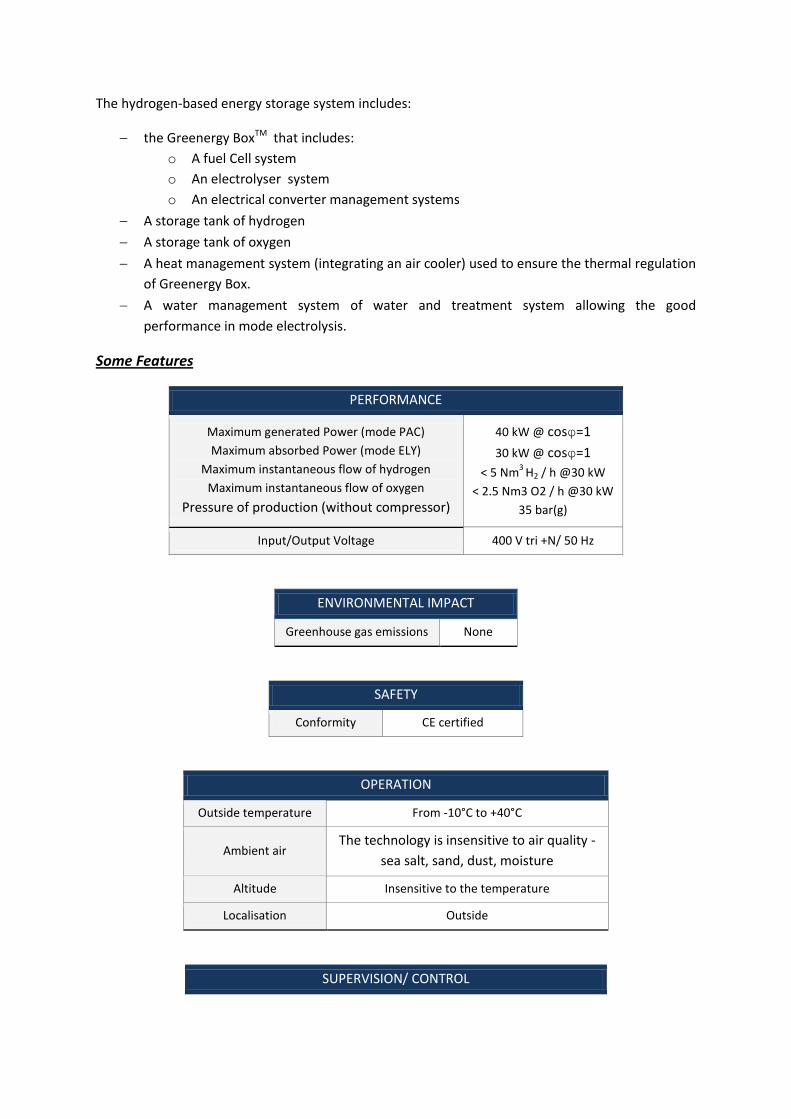
The hydrogen-based energy storage system includes:
the Greenergy BoxTM that includes:
o A fuel Cell system
o An electrolyser system
o An electrical converter management systems
A storage tank of hydrogen
A storage tank of oxygen
A heat management system (integrating an air cooler) used to ensure the thermal regulation
of Greenergy Box.
A water management system of water and treatment system allowing the good
performance in mode electrolysis.
Some Features
PERFORMANCE
Maximum generated Power (mode PAC)
Maximum absorbed Power (mode ELY)
Maximum instantaneous flow of hydrogen
Maximum instantaneous flow of oxygen
Pressure of production (without compressor)
40 kW @ cosφ=1
30 kW @ cosφ=1
< 5 Nm3
H2 / h @30 kW
< 2.5 Nm3 O2 / h @30 kW
35 bar(g)
Input/Output Voltage 400 V tri +N/ 50 Hz
ENVIRONMENTAL IMPACT
Greenhouse gas emissions None
SAFETY
Conformity CE certified
OPERATION
Outside temperature From -10°C to +40°C
Ambient air The technology is insensitive to air quality -
sea salt, sand, dust, moisture
Altitude Insensitive to the temperature
Localisation Outside
SUPERVISION/ CONTROL

Supervision at
distance
Configuration and state of the system
Logging of the operational data
Communications
Ethernet and dry contact
Supervision via connection ADSL Reference of
information towards possible GTC
STORAGE
Nature of the gas Hydrogen Oxygen
Capacity of the tanks
(active Gas) < 150 Nm3 <75 Nm3
Pressure of storage 35 bar(g)
Maximum autonomy
(mode FC)
210 kWh
For a power generated between 20 et 40 kW with cosφ=1
Time of load for the
maximum capacity
(mode ELY)
30 h
For an absorbed power equal to 30 kW with cosφ=1
Dimensions = 1.7 m; L = 3 m
which represent 6 m3
= 1.2 m; L = 3 m
Which represent 3 m3
Mass ~9t (filled of water) ~ 5t (filled of water)
Facility Vertical
Conformity CE Certified
Table 8-1: Technical specification of the Greenergy Box for La Croix-Valmer
The Greenergy BoxTM is installed in the new Kid Leisure Center building of the city. Regarding the French regulation, this type of building occupation is considered as a public building that has to follow precisely the building codes requirements. In France, such regulation is not adapted to the installation of hydrogen-energy applications since the word ‘hydrogen’ is even not mentioned anywhere in the texts. Therefore, one major challenge was to define the rules for the first installation of a hydrogen-energy storage system in adequacy to the existing safety strategy in public building regulations.
On account of a late involvement, the space attributed for the settlement of the Greenergy BoxTM system and the hydrogen and oxygen reservoirs, is quite restricted and located in the proximity of the reception area of the building, close to the building access road and a garage entrance, as shown in Figure below. Above the garage is found a multi-purpose hall and its terrace that gets a direct view of the hydrogen chain settlement.
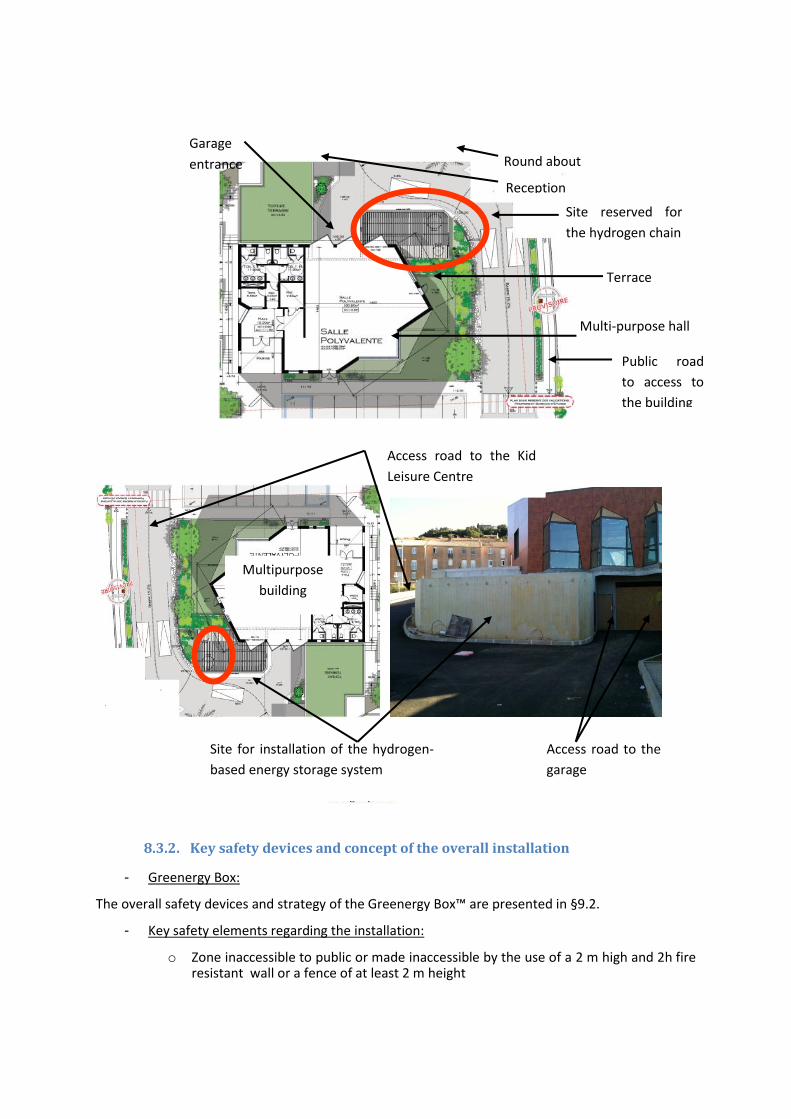
8.3.2. Key safety devices and concept of the overall installation
- Greenergy Box:
The overall safety devices and strategy of the Greenergy Box™ are presented in §9.2.
- Key safety elements regarding the installation:
o Zone inaccessible to public or made inaccessible by the use of a 2 m high and 2h fire resistant wall or a fence of at least 2 m height
Site for installation of the hydrogen-
based energy storage system
Access road to the Kid
Leisure Centre
Multipurpose
building
Access road to the
garage
Site reserved for
the hydrogen chain
Public road
to access to
the building
Reception
area
Round about
Multi-purpose hall
Terrace
Garage
entrance

o Zone is protected by a 2h fire resistant canopy to protect the system and the storage and/or the façade of the multi-purpose from thermal effects in case of fire
- Storage:
The quantities of hydrogen gas and oxygen stored are the following ones:
Hydrogen = 17 kg
Oxygen = 142 kg
Storages of oxygen and hydrogen are installed in a protected area by two-hour firewall protection,
and are overhung by a hood built out of two-hour fireproof and firebreak materials, including the
storage section completely.
Storages of hydrogen and oxygen are separated by two-hour firebreak wall. Storage capacities are
certified CE under the directive on pressure equipment (DESP) - 97/23/CE. The materials used are
compatible with hydrogen and oxygen.
Figure 8-6: Sight on the two hydrogen and oxygen tanks storage (except roof, not represented)

For maintenance reasons, two nitrogen bottles (standard B50 at 200bar) are installed near the
access door of the zone. These nitrogen bottles are positioned near the entry in order to facilitate
their handling.
- Isolation valves Each tank i.e. H2 and O2 is equipped with a manual safety valve and an electro-valve in order to
isolate storage from the installation. Safety manual valves and electro-valves are also positioned at
the entrance of the Greenergy Box. Therefore, in case of power cut or activation of a safety function,
both the storage tank and the Greenergy Box are isolated by the electro-valves.
- Emergency safety devices In case of emergency, two additional safety devices may be used on the installation:
An “Emergency Discharge Device” (DDU-Dispositif de Décharge d’Urgence) of the tanks, positioned outside of the technical premise with a protected access, enables to discharge the storage tanks in less than 8 minutes through the vent.
An emergency Stopping bottom (CPAU-Coup de Poing d’Arrêt d’Urgence) enables to isolate the gas supply at the tank and the container, disconnect the Greenergy Box™ from the electrical grid up to the electrical Voltage , which will imply the depressurization of the system through the vents installed on the roof of the building. Residual amount of hydrogen will subsist in the process.
- Connection to electrical installations of the building
The Greenergy Box is connected to the building via a specific electric control panel “Cupboard of
coupling”, shielded from the rest of the facilities of the building.
The electric control panels of connection are situated in inaccessible places to public (TGBT-Tableau
Général Basse Tension or Main Low-Voltage Board).
Electric wiring is fixed and walks on cable shelves not propagator of the flame, in accordance with
regulation EL 10. The cables used to connect the module Greenergy Box to the building, are part of
C2 category. The cross section of the cables through the two-hour firebreak partition of the building
is done by means of stuffing box respecting the two-hour firebreak degree.

- Gas Venting
The Greenergy Box™ and storages have two vents of evacuation, including one for hydrogen and the
other for oxygen. The lines of vent coming from storage and Greenergy Box™ are inter-connected
and channeled vertically along the versatile room. The end of the vents leave to 1 m above roof the
building and are bent with a 90° angle. The oxygen and hydrogen vents are directed with 90° one
compared to the other in order to discharge gases out of the building’s room in different directions.
The external pipes are protected mechanically.
Figure 8-7: Sight on the vents of evacuation of hydrogen and oxygen.

9. References
1. ECE/TRANS/WP.29/GRSP/2012/12, Draft global technical regulation on Hydrogen Fuelled
vehicle. Economic and social Council, United Nations.
2. California Fuel Cells Partnership, 2014. Available from: http://cafcp.org/ [accessed on
01.05.14].
3. HyFLEETE CUTE (2014). Available from: http://www.global-hydrogen-bus-
platform.com/Technology/Buses [accessed on 01.05.14].
4. Zaetta, R and Madden, B (2011). Next HyLights project. Deliverable 3.1: Hydrogen Fuel Cell
Bus Technology State of the Art Review.
5. Adams, P (2004). Identification of the optimum on-board storage pressure for gaseous
hydrogen city buses. European Integrated Hydrogen project – Phase 2 (EIHP2), March 2004.
6. Zalosh, R (2007). Blast waves and fireballs generated by hydrogen fuel tank rupture during
fire exposure. Proceedings on the 5th Seminar on Fire and Explosion Hazard, Edinburgh, UK,
23-27 April 2007, pp. 2154-2161.