![ARISTOTEL - ] ( v Z} } ( W] o} }µ o]vP td}}o v d Zv] µ (} …aristotel-project.eu/fileadmin/aristotel/public/news/...ARISTOTEL project would like to determine form by detailed, systematic](https://static.fdocuments.in/doc/165x107/5e5ea5a9b1c8290ee7388546/aristotel-v-z-w-o-ovp-tdo-v-d-zv-aristotel-aristotel.jpg)
Deliverable No. D4.11 Validation of models and criteria...
28
ACPO-GA-2010-266073 Deliverable D4.11 266073_ARISTOTEL_D3.9_Validation_of_models_and_criteria_for_ Aeroservoelastic_A/RPC_predictions Page 1 of 28 Aircraft and Rotorcraft Pilot Couplings – Tools and Techniques for Alleviation and Detection ACPO-GA-2010-266073 Deliverable No. D4.11 Validation of models and criteria for aeroservoelastic A/RPC predictions Contractual delivery date: July 31, 2013 Actual delivery date: August 1, 2013 Partner responsible for the Deliverable: UROMA3 Author(s): M. Gennaretti, J. Serafini, M. Molica Colella, UROMA3 Larisa Zaichik, TsAGI Hafid Smaili, Marcel Verbeek, NLR
Transcript of Deliverable No. D4.11 Validation of models and criteria...

ACPO-GA-2010-266073 Deliverable D4.11
266073_ARISTOTEL_D3.9_Validation_of_models_and_criteria_for_
Aeroservoelastic_A/RPC_predictions
Page 1 of 28
Aircraft and Rotorcraft Pilot Couplings – Tools and Techniques for Alleviation and Detection
ACPO-GA-2010-266073
Deliverable No. D4.11
Validation of models and criteria for aeroservoelastic A/RPC predictions
Contractual delivery date:
July 31, 2013
Actual delivery date:
August 1, 2013
Partner responsible for the Deliverable: UROMA3
Author(s):
M. Gennaretti, J. Serafini, M. Molica Colella, UROMA3
Larisa Zaichik, TsAGI
Hafid Smaili, Marcel Verbeek, NLR
ACPO-GA-2010-266073 Deliverable D4.11
266073_ARISTOTEL_D4.11_Validation_of_models_and_criteria_for_
Aeroservoelastic_A/RPC_predictions
Page 2 of 28
Dissemination level
PU Public X
PP Restricted to other programme participants (including the Commission Services)
RE Restricted to a group specified by the consortium (including the Commission
Services)
CO Confidential, only for members of the consortium (including the Commission
Services)
Document Information Table
Grant agreement no. ACPO-GA-2010-266073
Project full title ARISTOTEL – Aircraft and Rotorcraft Pilot Couplings – Tools and Techniques for Alleviation and Detection
Deliverable number D4.11
Deliverable title Validation of models and criteria for aeroservoelastic A/RPC predictions
Nature R
Dissemination level PU
Version 1.0
Work package number WP4
Work package leader 6
Partner responsible for Deliverable 5
Reviewer(s) Achim Ionita, STRAERO
Larisa Zaichik, TsAGI
The research leading to these results has received funding from the European Community's Seventh Framework Programme (FP7/2007-2013) under grant agreement no 266073.
The author is solely responsible for its content, it does not represent the opinion of the European Community and the Community is not responsible for any use that might be made of data appearing therein.
Revision Table
Version Date Modified Page/Section Author Comments
xx.xx.xx
ACPO-GA-2010-266073 Deliverable D4.11
266073_ARISTOTEL_D4.11_Validation_of_models_and_criteria_for_
Aeroservoelastic_A/RPC_predictions
Page 3 of 28
Executive Summary
This deliverable deals with the assessment and validation of theoretical models, as well as the criteria for predicting aero-servo-elastic instabilities with a pilot-in-the-loop. In this context, UROMA3 contribution is concerned with the prediction of aero-servo-elastic rotorcraft-pilot coupling phenomena, while TsAGI and NLR analyse the suitability of criteria for the prediction of aero-servo-elastic APCs. To these aims, also results of the aero-servo-elastic simulator campaigns coming from Task 4.2 are exploited.
Table of Contents
Document Information Table...................................................................................................... 2
Executive Summary ................................................................................................................... 3
1. Introduction ......................................................................................................................... 4
2. Summary of Work Performed ............................................................................................. 5
3. Results and Conclusion .................................................................................................... 11
4. Deviations ......................................................................................................................... 27
5. References ........................................................................................................................ 27
6. List of Abbreviations.......................................................................................................... 28

ACPO-GA-2010-266073 Deliverable D4.11
266073_ARISTOTEL_D4.11_Validation_of_models_and_criteria_for_
Aeroservoelastic_A/RPC_predictions
Page 4 of 28
1. Introduction
Amongst the aims of the project ARISTOTEL, of relevant importance is the reliable/accurate prediction of aeroservoelastic instabilities related to adverse interactions between pilot and vehicle. Indeed, it should provide the base for the definition of guidelines suitable for the design of modern/innovative air/rotor-craft configurations.
The problem of simulating the dynamics of helicopter with inclusion of pilot-in-the-loop requires the introduction of complex, non-linear theoretical formulations with hidden state dynamics. This implies that the stability analysis is not an easy task that might be performed following several different approaches, ranging from direct time marching solution of the complete formulation with observation of response damping, to eigenvalue analysis of the linearized piloted helicopter model.
This deliverable deals with the assessment and validation of theoretical models, as well as the criteria developed and applied for predicting aero-servo-elastic instabilities with a pilot-in-the-loop. The partners involved are UROMA3 for what concerns the prediction of aero-servo-elastic rotorcraft-pilot coupling phenomena, and TsAGI and NLR for the part dealing with the prediction of aero-servo-elastic APCs.
In the next sections the corresponding activity developed by these partners is presented. In order to validate the criteria adopted for A/RPC stability analysis, also results of the aero-servo-elastic simulator campaigns coming from Task 4.2 are exploited.
ACPO-GA-2010-266073 Deliverable D4.11
266073_ARISTOTEL_D4.11_Validation_of_models_and_criteria_for_
Aeroservoelastic_A/RPC_predictions
Page 5 of 28
2. Summary of Work Performed
In the following, the activity of each contributing partner is presented, each outlined in a dedicated section. First, UROMA3 tools and approaches aimed at RPC/PAO predictions to be validated are briefly described, and then the activity of fixed-wing partner (namely, TsAGI and NLR) is presented.
2.1. Contribution from UROMA3
In this deliverable results concerning the validation of models developed and criteria adopted by UROMA3 group to examine RPC/PAO stability of helicopters. Since the criteria adopted for the stability analysis are those based on the eigenvalue analysis of the linearized system model, significant effort has been spent on the development of mathematical formulations for the linearized description of complete helicopter configurations, with particular attention to the main rotor which is the most critical component of the rotorcraft. Details of the piloted helicopter modeling developed by UROMA3 have already been given in D3.4 [D3.4] and D3.9 [D3.9], thus in the following section it is only briefly summarized, while the criteria adopted for the RPC/PAO stability analysis are described in Section 2.1.2.
2.1.1. Outline of aeroservoelastic piloted helicopter modeling
The UROMA3 comprehensive helicopter simulation model, suitable for RPC analysis, is obtained by coupling flexible fuselage dynamics, main rotor aeroelasticity, control chain dynamics and pilot behavioural dynamics. The main rotor model interacts both with fuselage dynamics (through hub loads and motion) and with the control-chain servoelastic model which yields the rotor blade pitch controls derived from pilot's commands. The pilot behavioural model receives the vehicle motion as input and supplies the control lever displacement. Each component of the helicopter model is developed with a suitable number of degrees of freedom, representing the optimal trade-off between accuracy and computational efficiency. Main rotor aeroelastic model
A non-linear, bending-torsion, beam-like model that is valid for straight, slender, homogeneous, isotropic, non-uniform, twisted blades undergoing moderate displacements is applied to represent the structural dynamics of the main rotor [JoA-2010]. The resulting structural operator consists of a set of coupled, non-linear, differential equations governing the bending of the elastic axis (lead-lag and flap deflections) and the rotation of the cross sections (blade torsion). Blade aerodynamic loads may be simulated either by a sectional model with Pitt-Peters dynamic-inflow corrections to account for the three-dimensional effects from trailing vortices, or through a Boundary Element Method (BEM) solver for free-wake, potential flows. The BEM computational tool considered is based on a boundary integral equation formulation suited for the prediction of rotor aerodynamics, applicable to a wide range of flight configurations, with inclusion of those characterized by complex blade-vortex interactions [AIAAJ-2007,JoA-2010,D3.4]. The Galerkin approach is applied for the spatial integration of the resulting aeroelastic integro-differential formulation, while time responses are computed through a time-marching, Newmark-β numerical scheme. Once the rotor aeroelastic response is computed, the corresponding forces and moments at the hub attachment point are evaluated through a combination of aerodynamic and inertial blade loads (see [D3.4]). When linear time invariant (LTI) modelling is required for an eigenvalue analysis (like that necessary for application of the criteria adopted in this project for RPC/PAO stability analysis), the state-space representation of the rotor aeroelastic behaviour is identified

ACPO-GA-2010-266073 Deliverable D4.11
266073_ARISTOTEL_D4.11_Validation_of_models_and_criteria_for_
Aeroservoelastic_A/RPC_predictions
Page 6 of 28
through the approach presented in Ref. [CEAS-AJ] (see also [D3.9]). This approach requires the prediction of a set of harmonic perturbation responses by a time-marching aeroelastic solver. The accuracy of this solver characterizes that of the identified finite-state operator. It relates hub motion dofs and blade pitch controls to the corresponding loads transmitted to the fuselage by a constant-coefficient, linear, differential form, with the by-product of introducing some additional states deriving from wake vorticity and blade dynamics (indeed, blade dofs do not appear explicitly in this model, but equivalent internal dynamics simulates their influence). Fuselage model
In RPC occurrency, a crucial role is played by fuselage dynamics. In particular, as demonstrated by past investigations, pilot seat vibrations due to fuselage elastic dynamics are of fundamental importance in PAO phenomena [ARISTOTEL-ERF11,UR3-POLIMI-ERF08]. The fuselage model considered here is obtained by combining the rigid-body equations with those governing the elastic deformations. The rigid-body equations derive from the standard six dofs model coupled with the kinematics of the Euler angles for the definition of vehicle orientation, (linearized about an arbitrary steady flight condition, for LTI analyses). The main forcing terms of these equations are the loads at the main rotor hub, but contributions from the tail rotor and fuselage aerodynamics are taken into account, as well. Fuselage elastic dynamics are expressed through a linear modal approach with mass, damping and stiffness matrices identified through a FEM analysis dedicated to the evaluation of free-vibration modes of the unconstrained structure. It is forced by the projection of the main rotor and tail rotor loads onto the modal shapes derived from the eigenvectors given by the FEM analysis. Indeed, this is a convenient approach, in that the resulting elastic modes are such that rigid-body motion equations and elastic dynamics equations are coupled only through the forcing terms [UR3-POLIMI-ERF08]. Pilot and control-chain models
For the frequency range of interest in PAO phenomena (that are those of concern in aeroservoelastic RPC), the pilot acts as an inadvertent link between the seat motion and the controls, practically acting like a mechanical impedance. Passive (involuntary behaviour) models of helicopter pilots are introduced in terms of transfer functions between the seat acceleration (input), and the vertical acceleration of the pilot's hand (output). These vary as function of pilot mass, pilot workload, commands setting. One of the first attempts to model passive pilot behaviour was conducted by Mayo, who identified ectomorphic (lighter) and mesomorphic (heavier) pilot models that are particularly suited for vertical bouncing analysis, in a dedicated experimental campaign [MAYO]. However, in the RPC simulation tools it is possible to implement a generic pilot model expressed in terms of a transfer function. Thus, different models concerning pilot behaviors related to different workloads are already applicable and their influence on RPC/PAO may be examined. Pilot's commands are transmitted to rotor blades through the control chain. This transmission is modelled by second-order differential forms relating stick rotation (and pedals) to main rotor (and tail rotor) blade pitch controls.
2.1.2. Criteria for RPC/PAO stability analysis
UROMA3 has focused the attention to the analysis of PAO aeroservoelastic stability. As it is well known, it is a phenomenon that involves coupling among main rotor aeroelasticity, rigid-body fuselage dynamics, airframe elasticity, control chain, automatic flight control system and, of course, biodynamics and piloting [PAS].

ACPO-GA-2010-266073 Deliverable D4.11
266073_ARISTOTEL_D4.11_Validation_of_models_and_criteria_for_
Aeroservoelastic_A/RPC_predictions
Page 7 of 28
Several significant nonlinearities appear in the accurate mathematical modeling aiming at simulating PAO phenomena: of particular importance those concerning rotor blade structural dynamics and aerodynamics, as well as rigid-body motion. Despite this, since focusing on phenomena characterized by aeroservoelasticity, the stability analysis based on the solution of the system eigenproblem is that yielding the criteria used by UROMA3 to predict the proneness of a helicopter to adverse/catastrophic RPC/PAO events. Specifically, this criteria consists of determining the set of the eigenvalues associated to the linear model describing the comprehensive, flexible vehicle dynamics, with inclusion of pilot-in-the-loop, followed by the analysis of the sign of their real parts: indeed, as well known, they represent the damping of the corresponding eigenvectors (the fundamental modes of system dynamics) and hence the positive value of the real part of one of the eigenvalues means indefinite growth of system response to a perturbation, i.e. system instability. Therefore, the application of this criteria for the analysis of RPC/PAO stability requires a three-step procedure: first, from the complete, nonlinear vehicle dynamics model the variables equilibrium configuration related to an unperturbed given flight condition is determined, then the linearized system dynamics about the equilibrium configuration is identified, and finally its eigenanalysis is carried out. In details, for representing the vector of system variables, its equilibrium configuration, ,
is determined as solution of ( )
where ( ) denotes the nonlinear system operator, and denotes the forcing term vector; then, for , with representing a small perturbation of variables, following, for instance, the linear system identification approach presented in [D3.9] for rotor aeroelasticity, it is possible to derive the homogeneous small perturbation equation
with { }, where denotes additional states hidden in the nonlinear system description (for instance, these arise from rotor aerodynamics as deriving from wake vorticity dynamics). Finally, the equation above, recast in state-space form yields
where { } are the system state variables, whereas is the system matrix. The
eigenvalues of are the system eigenvalues that represent the dynamic behavior of the rotorcraft about the equilibrium configuration.
2.2. Contribution from TsAGI and NLR (fixed-wing)
It is known that high-frequency accelerations due to structural elasticity cause involuntary body and limb-manipulator system displacements, which interfere with pilot voluntary control activity (biodynamical feedthrough, BDFT) and may be a reason for pilot rating worsening. As control inceptor (manipulator) is one of the main elements in the limb-manipulator system, its characteristics may affect the BDFT and, as a consequence, pilot ratings of aircraft handling qualities (HQ). The variety of parameters affecting pilot ratings and their interdependence make experimental study of aircraft HQ difficult. Thus, criterion is required which would allow analytical HQ assessment with regard to aircraft structural elasticity characteristics and other parameters, such as inceptor characteristics, affecting HQ pilot ratings. Experiments conducted in the course of the 1st and 2nd test campaign [ARISTOTEL D4.2, ARISTOTEL D4.5, ARISTOTEL D4.7] discovered the effect of manipulator type and its feel system characteristics on BDFT describing functions and formed experimental database to validate the developed criteria. The present report describes the idea of the criterion and presents its validation.
ACPO-GA-2010-266073 Deliverable D4.11
266073_ARISTOTEL_D4.11_Validation_of_models_and_criteria_for_
Aeroservoelastic_A/RPC_predictions
Page 8 of 28
2.2.1. Formulation of the criterion
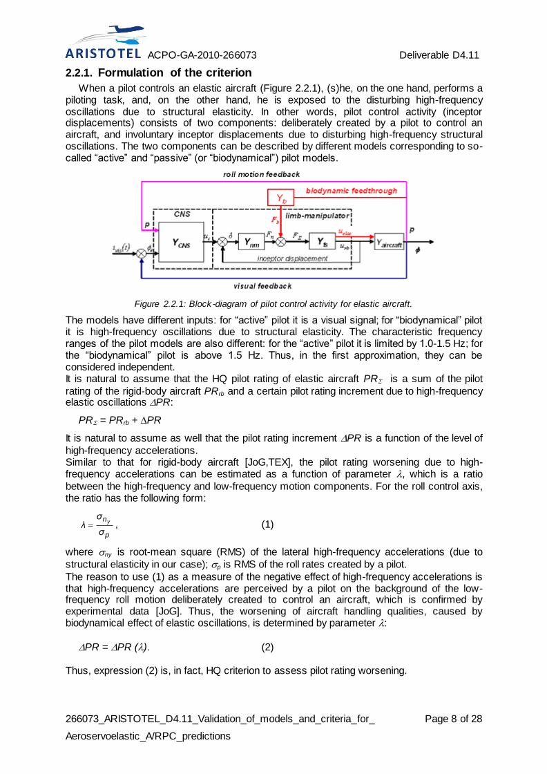
When a pilot controls an elastic aircraft (Figure 2.2.1), (s)he, on the one hand, performs a piloting task, and, on the other hand, he is exposed to the disturbing high-frequency oscillations due to structural elasticity. In other words, pilot control activity (inceptor displacements) consists of two components: deliberately created by a pilot to control an aircraft, and involuntary inceptor displacements due to disturbing high-frequency structural oscillations. The two components can be described by different models corresponding to so-called “active” and “passive” (or “biodynamical”) pilot models.
Figure 2.2.1: Block-diagram of pilot control activity for elastic aircraft.
The models have different inputs: for “active” pilot it is a visual signal; for “biodynamical” pilot it is high-frequency oscillations due to structural elasticity. The characteristic frequency ranges of the pilot models are also different: for the “active” pilot it is limited by 1.0-1.5 Hz; for the “biodynamical” pilot is above 1.5 Hz. Thus, in the first approximation, they can be considered independent. It is natural to assume that the HQ pilot rating of elastic aircraft PR is a sum of the pilot
rating of the rigid-body aircraft PRrb and a certain pilot rating increment due to high-frequency elastic oscillations PR:
PR = PRrb + PR
It is natural to assume as well that the pilot rating increment PR is a function of the level of
high-frequency accelerations. Similar to that for rigid-body aircraft [JoG,TEX], the pilot rating worsening due to high-frequency accelerations can be estimated as a function of parameter , which is a ratio
between the high-frequency and low-frequency motion components. For the roll control axis, the ratio has the following form:
p
n
σ
σλ
y , (1)
where ny is root-mean square (RMS) of the lateral high-frequency accelerations (due to
structural elasticity in our case); p is RMS of the roll rates created by a pilot.
The reason to use (1) as a measure of the negative effect of high-frequency accelerations is that high-frequency accelerations are perceived by a pilot on the background of the low-frequency roll motion deliberately created to control an aircraft, which is confirmed by experimental data [JoG]. Thus, the worsening of aircraft handling qualities, caused by biodynamical effect of elastic oscillations, is determined by parameter :
PR = PR (). (2)
Thus, expression (2) is, in fact, HQ criterion to assess pilot rating worsening.

ACPO-GA-2010-266073 Deliverable D4.11
266073_ARISTOTEL_D4.11_Validation_of_models_and_criteria_for_
Aeroservoelastic_A/RPC_predictions
Page 9 of 28
2.2.2. Calculation of parameter λ and HQ Criterion
Generally, pilot activities spectrum characteristics depend not only on the aircraft characteristics, but also on the piloting conditions: piloting task, urgency for high performance and turbulence. To estimate whether aircraft is prone to biodynamical interaction, it is natural to consider those piloting conditions, in which a pilot is more susceptible to the influence of lateral accelerations. The effect of high-frequency accelerations is especially pronounced when no turbulence occurs and the pilot is not occupied by a piloting task, but manipulates the stick at will to evaluate HQ in an open loop. That is why the diagram to calculate parameter is the pilot-
aircraft open-loop model. To calculate RMS of the lateral accelerations (ny) and roll rates (p) in (1), we use random
function theory. Assuming the pilot control activity is a stationary random process, the models of the active and biodynamical pilots can be presented as white noise passing through the corresponding filters, as it is shown in Figure 2.2.2. For the active pilot model, it is a filter, which reflects pilot activity to control aircraft in roll; for the biodynamical pilot model, it is a filter, which describes pilot’s involuntary control activity caused by high-frequency lateral accelerations.
Figure 2.2.2: The models to calculate ny and p.
In this case, the values of ny and p can be calculated as follows:
ωdωjYωjYπ
σ bpnn
22
yy 2
1,
ωdωjYωjYπ
σ appp
22
2
1, (3)
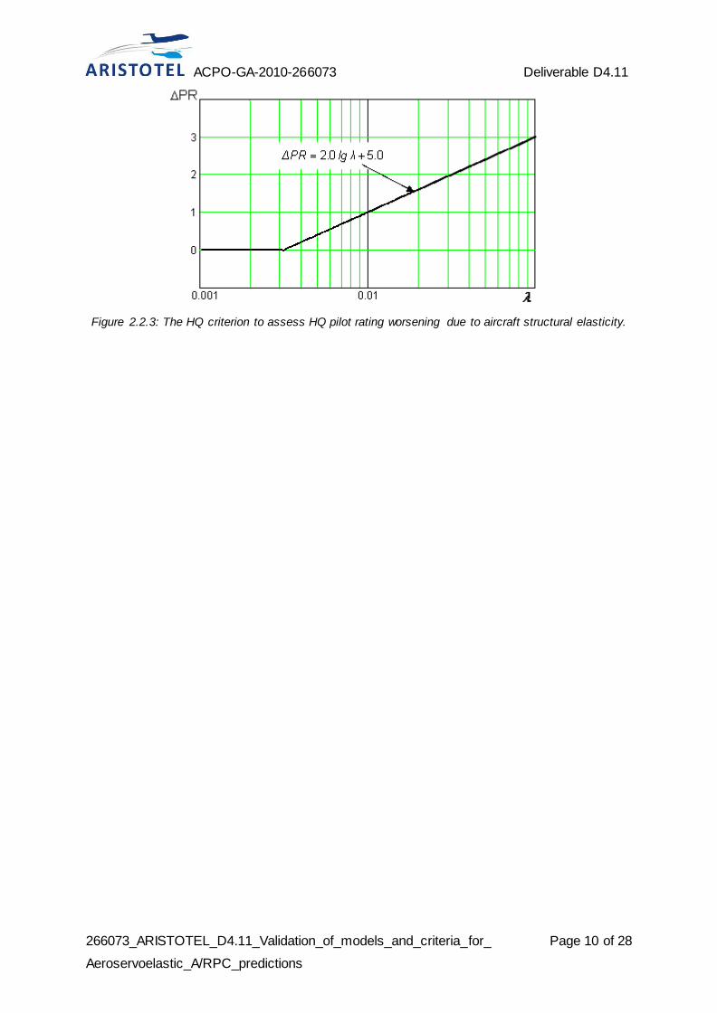
where Yny is aircraft transfer function for lateral accelerations; Yp is transfer function for roll rate; Yap is transfer function for the “active” pilot; Ybp is transfer function for the “biodynamical” pilot. The calculations and experimental data allowed to formulate the following criterion: the pilot rating worsening due to lateral accelerations caused by structural elasticity can be assessed with the curve shown in Figure 2.2.3.
ACPO-GA-2010-266073 Deliverable D4.11
266073_ARISTOTEL_D4.11_Validation_of_models_and_criteria_for_
Aeroservoelastic_A/RPC_predictions
Page 10 of 28
Figure 2.2.3: The HQ criterion to assess HQ pilot rating worsening due to aircraft structural elasticity.

ACPO-GA-2010-266073 Deliverable D4.11
266073_ARISTOTEL_D4.11_Validation_of_models_and_criteria_for_
Aeroservoelastic_A/RPC_predictions
Page 11 of 28
3. Results and Conclusion
3.1. UROMA3 contribution
The numerical investigation presented in the following concerns validation of models and criteria applied by UROMA3 for the RPC/PAO stability analysis, and described in Sects. 2.1.1 and 2.1.2. For all of the results the helicopter configuration examined is the MBB Bo-105 light-weight helicopter models detailed in Ref. [D3.1].
3.1.1. Model validation
In this section, validations regarding different aspects of the piloted helicopter modeling aimed at providing the system matrix for application of the eigenvalue criteria for RPC/PAO stability analysis are presented. These concern helicopter time responses to given pilot inputs, rational matrix approximation of rotor aeroelastic transfer functions, finite-state hub loads representation, and finally passive pilot modeling, Helicopter response to control inputs
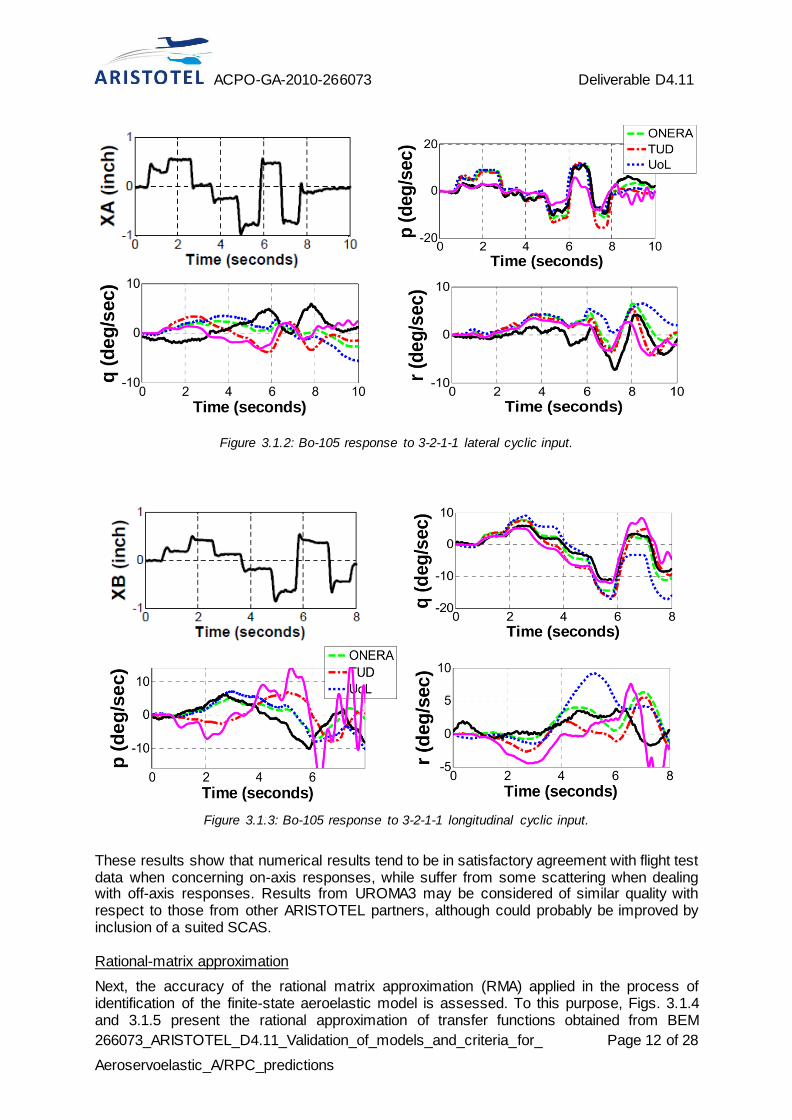
First, results from the comprehensive aeroservoelastic helicopter dealing with the response to given pilot command inputs have been validated by comparison with predictions from other ARISTOTEL partners, as well as with experimental in-flight data. Specifically, they concern the Bo-105 test campaign described in [D2.2], where responses to 3-2-1-1 collective, longitudinal cyclic and lateral cyclic inputs during an 80 kts level flight have been monitored. In [D2.2] also numerical predictions from ONERA, UoL and TUD have been presented and are here reported for comparison.
Figure 3.1.1: Bo-105 response to 3-2-1-1 collective input.
Figure 3.1.1 shows the collective input and the corresponding responses, with the pink curves representing the results from UROMA3 code without activation of a SCAS. Similarly, Figs. 3.1.2 and 3.1.3 present the responses to lateral and longitudinal cyclic, respectively.
ACPO-GA-2010-266073 Deliverable D4.11
266073_ARISTOTEL_D4.11_Validation_of_models_and_criteria_for_
Aeroservoelastic_A/RPC_predictions
Page 12 of 28
Figure 3.1.2: Bo-105 response to 3-2-1-1 lateral cyclic input.
Figure 3.1.3: Bo-105 response to 3-2-1-1 longitudinal cyclic input.
These results show that numerical results tend to be in satisfactory agreement with flight test data when concerning on-axis responses, while suffer from some scattering when dealing with off-axis responses. Results from UROMA3 may be considered of similar quality with respect to those from other ARISTOTEL partners, although could probably be improved by inclusion of a suited SCAS. Rational-matrix approximation
Next, the accuracy of the rational matrix approximation (RMA) applied in the process of identification of the finite-state aeroelastic model is assessed. To this purpose, Figs. 3.1.4 and 3.1.5 present the rational approximation of transfer functions obtained from BEM

ACPO-GA-2010-266073 Deliverable D4.11
266073_ARISTOTEL_D4.11_Validation_of_models_and_criteria_for_
Aeroservoelastic_A/RPC_predictions
Page 13 of 28
aerodynamics in hovering flight, while Figs. 3.1.6 and 3.1.7 show the rational approximation of a transfer function for forward flight condition with advance ratio µ=0.3. Specifically, Figs. 3.1.4 and 3.1.5 concern hub axial force vs hub axial velocity and hub roll moment vs lateral cyclic pitch, respectively, whereas Figs. 3.1.6 and 3.1.7 regard hub axial force vs collective pitch and hub pitch moment vs lateral cyclic pitch.
Figure 3.1.4: Transfer function between hub axial
force and velocity. BEM vs RMA, hovering flight.
Figure 3.1.5: Transfer function between hub roll
moment and lateral cyclic pitch. BEM vs RMA,
hovering flight.
Figure 3.1.6. Transfer function between hub axial
force and collective pitch. BEM vs RMA, µ=0.3.
Figure 3.1.7. Transfer function between hub pitch
moment and lateral cyclic pitch. BEM vs RMA,
µ=0.3.
These figures demonstrate the high level of accuracy of the approximation of the main rotor aeroelastic transfer functions that may be obtained through the rational matrix form applied. It guarantees a very good level of accuracy of the process that provides the finite-state representation of the LTI aeroelastic rotor model, in the process of identification of the linearized system representation suitable for the eigenvalue stability analysis.

ACPO-GA-2010-266073 Deliverable D4.11
266073_ARISTOTEL_D4.11_Validation_of_models_and_criteria_for_
Aeroservoelastic_A/RPC_predictions
Page 14 of 28
Hub loads finite-state representation
The overall quality of the differential, LTI, finite-state model in describing the rotor-hub perturbation forces and moments is assessed by comparisons with the predictions given by the non-linear, time-marching (NLTM) solution of the complete aeroelastic rotor model. These are conceived as responses to the following arbitrary perturbation of one of the command inputs, ,
( )
with . For the hovering flight condition, the thrust generated when this perturbation regards the collective pitch angle is shown in Fig. 3.1.8, both as predicted by the non-linear, time-marching solver and as given by the state-space model. The comparison demonstrates that the simulation of the aeroelastic system provided by the LTI, finite-state formulation is very accurate, indeed. However, in the analysis of hovering configurations the time-constant approximation of the aeroelastic system does not affect the solution, and the validation concerns only the linearization process and the reduction to a finite number of state variables.
Figure 3.1.8: Hub thrust response in hovering
flight. LTI vs NLTM.
Figure 3.1.9: Hub rolling moment response in
forward flight. LTI vs NLTM.
Unlike, in the forward-flight condition at µ=0.3, the aeroelastic response is significantly affected by time-periodic coefficient terms. For this configuration, Fig. 3.1.9 depicts the hub rolling moment due to perturbations of the lateral cyclic pitch control, as predicted by the NLTM solver and by the LTI, finite-state model. Also in this case, although (as expected) some differences may be observed in the response amplitude, these remain very small, with phase and amplitude decay very well captured. Thus, it is demonstrated that, even for forward flight conditions, the LTI, finite-state model is suitable for the accurate representation of the aeroelastic rotor hub loads. Passive pilot modeling
Pilot behavior description is a crucial component of the piloted helicopter model. For aeroservoelastic PAO analyses the response frequencies involved are such that an inadvertent pilot actions take place. This suggest the application of the so-called passive pilot models, typically identified through experimental tests. These are dependent on pilot mass, pilot expertise and workload.
ACPO-GA-2010-266073 Deliverable D4.11
266073_ARISTOTEL_D4.11_Validation_of_models_and_criteria_for_
Aeroservoelastic_A/RPC_predictions
Page 15 of 28
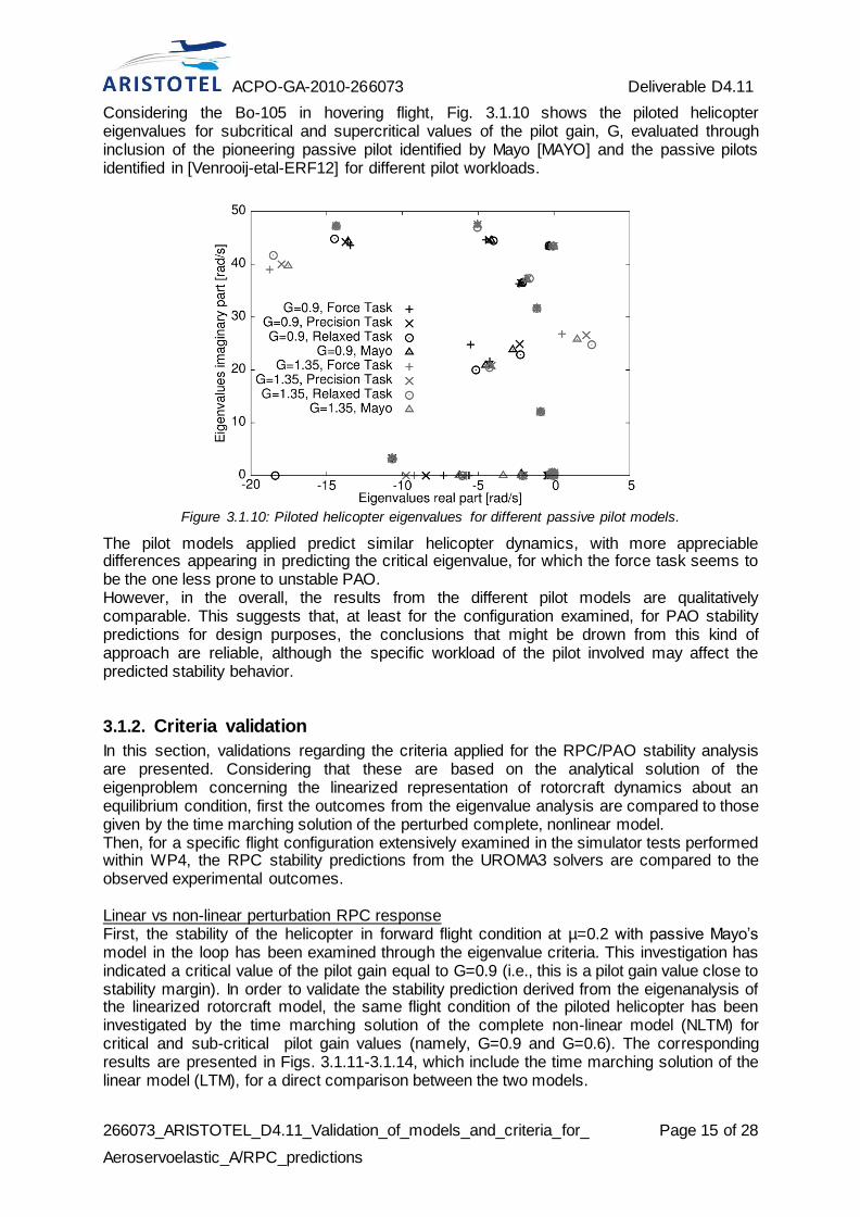
Considering the Bo-105 in hovering flight, Fig. 3.1.10 shows the piloted helicopter eigenvalues for subcritical and supercritical values of the pilot gain, G, evaluated through inclusion of the pioneering passive pilot identified by Mayo [MAYO] and the passive pilots identified in [Venrooij-etal-ERF12] for different pilot workloads.
Figure 3.1.10: Piloted helicopter eigenvalues for different passive pilot models.
The pilot models applied predict similar helicopter dynamics, with more appreciable differences appearing in predicting the critical eigenvalue, for which the force task seems to be the one less prone to unstable PAO. However, in the overall, the results from the different pilot models are qualitatively comparable. This suggests that, at least for the configuration examined, for PAO stability predictions for design purposes, the conclusions that might be drown from this kind of approach are reliable, although the specific workload of the pilot involved may affect the predicted stability behavior.
3.1.2. Criteria validation
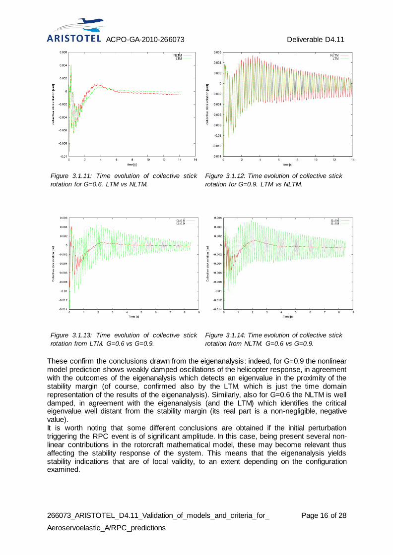
In this section, validations regarding the criteria applied for the RPC/PAO stability analysis are presented. Considering that these are based on the analytical solution of the eigenproblem concerning the linearized representation of rotorcraft dynamics about an equilibrium condition, first the outcomes from the eigenvalue analysis are compared to those given by the time marching solution of the perturbed complete, nonlinear model. Then, for a specific flight configuration extensively examined in the simulator tests performed within WP4, the RPC stability predictions from the UROMA3 solvers are compared to the observed experimental outcomes. Linear vs non-linear perturbation RPC response First, the stability of the helicopter in forward flight condition at µ=0.2 with passive Mayo’s model in the loop has been examined through the eigenvalue criteria. This investigation has indicated a critical value of the pilot gain equal to G=0.9 (i.e., this is a pilot gain value close to stability margin). In order to validate the stability prediction derived from the eigenanalysis of the linearized rotorcraft model, the same flight condition of the piloted helicopter has been investigated by the time marching solution of the complete non-linear model (NLTM) for critical and sub-critical pilot gain values (namely, G=0.9 and G=0.6). The corresponding results are presented in Figs. 3.1.11-3.1.14, which include the time marching solution of the linear model (LTM), for a direct comparison between the two models.
ACPO-GA-2010-266073 Deliverable D4.11
266073_ARISTOTEL_D4.11_Validation_of_models_and_criteria_for_
Aeroservoelastic_A/RPC_predictions
Page 16 of 28
Figure 3.1.11: Time evolution of collective stick
rotation for G=0.6. LTM vs NLTM.
Figure 3.1.12: Time evolution of collective stick
rotation for G=0.9. LTM vs NLTM.
Figure 3.1.13: Time evolution of collective stick
rotation from LTM. G=0.6 vs G=0.9.
Figure 3.1.14: Time evolution of collective stick
rotation from NLTM. G=0.6 vs G=0.9.
These confirm the conclusions drawn from the eigenanalysis: indeed, for G=0.9 the nonlinear model prediction shows weakly damped oscillations of the helicopter response, in agreement with the outcomes of the eigenanalysis which detects an eigenvalue in the proximity of the stability margin (of course, confirmed also by the LTM, which is just the time domain representation of the results of the eigenanalysis). Similarly, also for G=0.6 the NLTM is well damped, in agreement with the eigenanalysis (and the LTM) which identifies the critical eigenvalue well distant from the stability margin (its real part is a non-negligible, negative value). It is worth noting that some different conclusions are obtained if the initial perturbation triggering the RPC event is of significant amplitude. In this case, being present several non-linear contributions in the rotorcraft mathematical model, these may become relevant thus affecting the stability response of the system. This means that the eigenanalysis yields stability indications that are of local validity, to an extent depending on the configuration examined.

ACPO-GA-2010-266073 Deliverable D4.11
266073_ARISTOTEL_D4.11_Validation_of_models_and_criteria_for_
Aeroservoelastic_A/RPC_predictions
Page 17 of 28
Figure 3.1.15: Piloted helicopter eigenvalues for different passive pilot models identified in T4.2.
Further, Fig. 3.1.15 presents helicopter root loci for different passive pilot models, with gain ranging from G=0 to G=1.5. These results have been obtained with pilot models identified through the simulator tests made in Liverpool within Task 4.2. For all pilot models, increasing the gain make the RPC unstable, with the forth pilot model more prone to lead to instability. This seems to be in agreement with the experimental observations. In addition, similarly to what observed in the simulator tests, eliminating elastic dofs from the helicopter model considerably increases the gain value for which instability arise. Taking into consideration the above observations, the stability criteria applied, in addition to be extremely convenient for design applications, may be considered validated for RPC/PAO analysis by the results presented.
3.1.3. Final remarks
Numerical investigations have been presented to assess and validate piloted helicopter modeling for RPC analysis developed by UROMA3, as well as to validate the criteria adopted for RPC/PAO stability prediction. Observing that the piloted helicopter state matrix to be applied in the eigenanalysis is the results of a multi-step process, each computational tool involved has been successfully validated, separately. Specifically these are the tool for the helicopter response to controls, the tool for the rational approximation of transfer functions, the finite-state rotor model and the passive pilot models considered. Further, the eigenvalue analysis used as stability assessment criteria has been successfully validated against time marching solutions of the complete non-linear piloted helicopter model. To summarize, the results presented confirm that the approach developed by UROMA3 is suitable for RPC/PAO phenomena examination.

ACPO-GA-2010-266073 Deliverable D4.11
266073_ARISTOTEL_D4.11_Validation_of_models_and_criteria_for_
Aeroservoelastic_A/RPC_predictions
Page 18 of 28
3.2. TsAGI and NLR contribution (fixed-wing)
3.2.1. Identification of pilot models
To use (2) for the assessment of the effect of structural elasticity and inceptor characteristics, we need to know transfer functions of the “active” and “biodynamical” pilot models in (3). The selection and identification of the transfer functions was performed on the basis of experimental data received in [ARISTOTEL D.3-6].
“Active” Pilot Model
To select and identify the transfer function for the “active” pilot we need, first of all, to determine the factors affecting the model. For this, series of experiments were conducted.
Effect of accelerations Experiments were conducted in flight simulator PSPK-102 of TsAGI. The description of experimental procedure is given in [ARISTOTEL D.4-7]. The aircraft model was a model of generic aircraft with 3-mode structural elasticity (1.5 Hz, 2.5 Hz and 3.5 Hz). Experiments were conducted with and without platform motion. The pilots performed roll compensatory tracking task; a wheel was used as a control inceptor. An example of pilot describing functions calculated using Fast Fourier Transform is presented in Figure 3.2.1. It is seen that the platform motion does not noticeably affect the describing function, in particular in the frequency range, typical of pilot control activities (up to 1.5 Hz).
Figure 3.2.1: Active pilot describing functions demonstrating effect of high-frequency lateral
accelerations
Effect of feel system characteristics Experiments were conducted on flight simulators of TsAGI (PSPK-102) and NLR (GRACE). The detailed description of experimental procedure is given in [ARISTOTEL D.4-5]. The aircraft model was a model of generic aircraft. The pilots performed roll compensatory tracking task. The forcing function for simulator platform was sum of sines. Three types of control inceptors were considered: traditional wheel, sidestick and center stick. All the inceptors were loaded by the electrical loading system, which allows flexible changing of feel system characteristics. The manipulator forces were modeled in accordance with the following equation:
pfrbrδδFδFδFδFδFδm
signsign ,
where: m is inceptor mass, δF is damping, Fδ is force gradient, Fbr is breakout force, Ffr is
friction, Fp is pilot force. Pilot describing functions received for center and side stick for different values of inceptor force gradient and damping are shown in Figures 3.2.2 and 3.2.3.

ACPO-GA-2010-266073 Deliverable D4.11
266073_ARISTOTEL_D4.11_Validation_of_models_and_criteria_for_
Aeroservoelastic_A/RPC_predictions
Page 19 of 28
Figure 3.2.2: Effect of inceptor damping on the describing functions of the active pilot model.
Figure 3.2.3: Effect of inceptor force gradient on the describing functions of the active pilot model.

ACPO-GA-2010-266073 Deliverable D4.11
266073_ARISTOTEL_D4.11_Validation_of_models_and_criteria_for_
Aeroservoelastic_A/RPC_predictions
Page 20 of 28
It is seen that the model of the active pilot does not practically depend on inceptor feel system characteristics, at least within the frequencies typical of pilot control activity (up to 1 Hz).
Effect of control sensitivity The active pilot model is a model, which describes pilot activity within the frequency range typical of piloting. It is known that within this frequency range a pilot can adjust his gain in accordance with the aircraft gain. This inherent property of a pilot is illustrated in Figure 3.2.4.
Figure 3.2.4: Effect of control sensitivity on active pilot model.
It is seen that as aircraft gain (control sensitivity) increases by factor K, a pilot changes his gain correspondingly by factor 1/K in order to make pilot-aircraft system cutoff frequency constant. At the same time, the amplitudes of the active pilot frequency response at the frequencies higher than 1 Hz are almost the same for different aircraft gains. The pilot model phase remains one and the same for different aircraft gains within the whole frequency range considered. Thus, the only factor, which has any noticeable impact on active pilot describing function, is the aircraft control sensitivity. To take this into account, we can use the following filter to describe the active pilot activity:
KKωs
Y pilot1
-act (4)
where K is an aircraft gain (control sensitivity) in the roll rate transfer function; K* is a certain constant, which can be interpreted as a “characteristic” value of the gain K; =1 rad/s. Parameter is to provide identical dimension in the denominator of the formula.
In the control systems, which are controlled by inceptor displacements, the value of control sensitivity depends on inceptor type and its travel capabilities. For example, for a sidestick, which displacements are 3 times less than for the wheel, the optimum value of control sensitivity is approximately 3 times less than that for the wheel. This enables us to assume that the value of the “characteristic” gain K* depends on inceptor type in the same proportion as the optimum control sensitivity.
“Biodynamical” Pilot Model
The involuntary body and limb displacements pass through the manipulator to the aircraft control system and can amplify the high-frequency accelerations. Due to the fact the inceptor is in the closed loop of biodynamic interaction (Figure 1.2.1), its feel system characteristics can affect the biodynamic interaction (BDI).

ACPO-GA-2010-266073 Deliverable D4.11
266073_ARISTOTEL_D4.11_Validation_of_models_and_criteria_for_
Aeroservoelastic_A/RPC_predictions
Page 21 of 28
To identify the “biodynamical” pilot model and to study the factors which can affect the model, special biodynamic tests were conducted on flight simulators TsAGI (PSPK-102) and NLR (GRACE). The human pilots were instructed to keep the inceptor in the vicinity of the reference position in presence of lateral accelerations produced by flight simulator motion system. The more detailed description of experiments is given in [ARISTOTEL D.3-6]. As it was stated in previous publications (see, for example, [BRISBANE]), within a limited range of friction and breakout forces variation, the effect of breakout force on BDFT is somewhat similar to the effect of force gradient, and the effect of friction is similar to the effect of damping. Thus, we pay here greater attention to the effect of force gradient and damping.
Figure 3.2.5: Comparison of the BDI for different types of control inceptors.
Figure 3.2.5 presents experimental results on biodynamic interaction for different types of manipulators, their feel system characteristics being optimum. The data were received in TsAGI’s PSPK-102 and NLR’s GRACE. Figure 3.2.6 presents effect of force gradient and damping for the sidestick.
Figure 3.2.6: Effect force gradient and damping on BDI for the sidestick .
ACPO-GA-2010-266073 Deliverable D4.11
266073_ARISTOTEL_D4.11_Validation_of_models_and_criteria_for_
Aeroservoelastic_A/RPC_predictions
Page 22 of 28
Analysis of this and other data can be summarized as follows: biodynamical interaction (biodynamical pilot model) depends on inceptor type: the
smallest BDI is observed for the wheel; force gradient increase leads to BDI diminishing, but its variation may result in rigid-body
handling quality worsening inceptor damping is the most effective method to suppress biodynamical interaction,
since it considerably reduces the high-frequency inceptor oscillations, and, at the same time, does not cause deterioration of pilot ratings of rigid-body HQ in a wide range of its variation.
Comparison of the calculated and experimental describing functions showed that their adequate agreement is achieved if we use the following transfer function:
12
1
1
1Y
1122
1
bpsζTsTsT
TsK)s(
I (5)
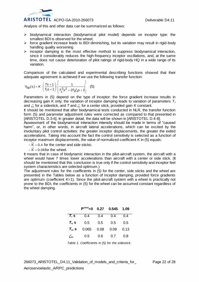
Parameters in (5) depend on the type of inceptor: the force gradient increase results in decreasing gain K only; the variation of inceptor damping leads to variation of parameters T1 and 1 for a sidestick, and T and 1 for a center stick, provided gain K constant.
It should be mentioned that after biodynamical tests conducted in NLR, the transfer function form (5) and parameter adjustment rules were corrected as compared to that presented in [ARISTOTEL D.3-6]. In greater detail, the data will be shown in [ARISTOTEL D.4-8]. Assessment of the biodynamical interaction intensity should be made in terms of “caused harm”, or, in other words, in aircraft lateral accelerations, which can be excited by the involuntary pilot control activities: the greater inceptor displacements, the greater the exited accelerations. Taking into account the fact the control sensitivity is selected as a function of inceptor maximum displacements, the value of normalized coefficient K in (5) equals:
- 0.4K for the center and side sticks;
- 0.06K for the wheel. It means that in case of biodynamic interaction in the pilot-aircraft system, the aircraft with a wheel would have 7 times lower accelerations than aircraft with a center or side stick. (It should be mentioned that this conclusion is true only if the control sensitivity and inceptor feel system characteristics are selected optimum.) The adjustment rules for the coefficients in (5) for the center, side sticks and the wheel are presented in the Tables below as a function of inceptor damping, provided force gradients are optimum (coefficient K=1). Since the pilot-aircraft system with a wheel is practically not prone to the BDI, the coefficients in (5) for the wheel can be assumed constant regardless of the wheel damping.
Р
xdot=0 0.27 0.545 1.09
T, s 0.4 0.4 0.4 0.4
TI, s 0.5 0.5 0.5 0.5
T1, s 0.065 0.08 0.09 0.13
1, 0.5 0.6 0.7 0.8
Table 1. Coefficients in (5) for the sidestick .
ACPO-GA-2010-266073 Deliverable D4.11
266073_ARISTOTEL_D4.11_Validation_of_models_and_criteria_for_
Aeroservoelastic_A/RPC_predictions
Page 23 of 28
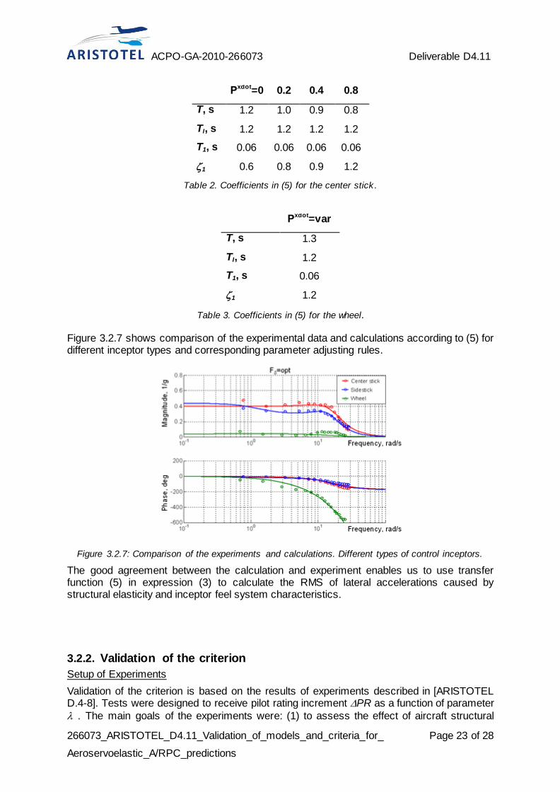
Рxdot=0 0.2 0.4 0.8
T, s 1.2 1.0 0.9 0.8
TI, s 1.2 1.2 1.2 1.2
T1, s 0.06 0.06 0.06 0.06
1 0.6 0.8 0.9 1.2
Table 2. Coefficients in (5) for the center stick .
Рxdot=var
T, s 1.3
TI, s 1.2
T1, s 0.06
1 1.2
Table 3. Coefficients in (5) for the wheel.
Figure 3.2.7 shows comparison of the experimental data and calculations according to (5) for different inceptor types and corresponding parameter adjusting rules.
Figure 3.2.7: Comparison of the experiments and calculations. Different types of control inceptors.
The good agreement between the calculation and experiment enables us to use transfer function (5) in expression (3) to calculate the RMS of lateral accelerations caused by structural elasticity and inceptor feel system characteristics.
3.2.2. Validation of the criterion
Setup of Experiments
Validation of the criterion is based on the results of experiments described in [ARISTOTEL D.4-8]. Tests were designed to receive pilot rating increment PR as a function of parameter
. The main goals of the experiments were: (1) to assess the effect of aircraft structural

ACPO-GA-2010-266073 Deliverable D4.11
266073_ARISTOTEL_D4.11_Validation_of_models_and_criteria_for_
Aeroservoelastic_A/RPC_predictions
Page 24 of 28
elasticity on pilot rating increment; (2) to assess the effect of inceptor feel system characteristics on the pilot ratings of the elastic aircraft. For criterion validation, the results received in PSPK-102 TsAGI were used. The aircraft model was a model of generic transport aircraft with 3-mode structural elasticity (1.5 Hz, 2.5 Hz and 3.5 Hz). The model was developed to assess all factors affecting biodynamic pilot-aircraft interaction: structural elasticity mode frequencies and amplitudes, rigid-body control sensitivity, and inceptor feel system characteristics. The description of the model is given in [D3.4]. Traditional wheel and sidestick were considered being the main control inceptors used nowadays in the modern airliners.
The biodynamic interaction is the most demonstrative when pilots perform abrupt control inputs provoking high-frequency elastic oscillations. Taking this fact into account, the following piloting tasks were selected:
1. Gust landing. Initial altitude 262 ft, heading 0, distance from the runway 0.81 miles. At 115 ft altitude a side step-wise left or right (random) wind gust is introduced, which leads to aircraft rolling and lateral drifting. To compensate for the aircraft motion, a pilot should respond quickly to align the aircraft along the runway avoiding large bank angles.
2. Tracking the “jumping” runway. The initial altitude is 50 ft, heading and bank angle are zero. In the course of experiment the runway right- and left-side shifting is simulated in turns every 20 seconds. The size of shifting is equal to the half-size of runway 98 ft. The pilot is to align aircraft along the runway centerline after every runway “jump”.
3. Roll tracking task. The pilot is to compensate for the tracking error, indicated on the head-up display as a moving bar. The visual input is a sum of sines.
Three experienced pilots participated in experiments. After a pilot performs all piloting tasks for the considered configuration of structural elasticity and inceptor feel system characteristics, he gives a final pilot rating of aircraft handling quality both for the rigid-body and elastic-body aircraft. The pilot rating increment DPR is determined as the difference between the pilot ratings given for the elastic aircraft and rigid-body aircraft for the same control sensitivity characteristics and inceptor feel system characteristics. To approach the common regularities, DPR received for all pilots were averaged.
Analysis of Experimental Data
Usually in real airplanes and in most cases observed in our experiments, the high-frequency accelerations due to structural elasticity cause biodynamical effect resulting in aircraft HQ worsening, which degree depends on the acceleration spectral characteristics. However, sometimes the accelerations can cause biodynamical interaction, which makes further piloting problematic or impossible at all, and leads to abrupt pilot rating degradation. Switching from biodynamical effect to biodynamical interaction depends on a number of factors. Conducted experiments allowed us to assume type of control inceptor and acceleration spectral characteristics to be the triggers for the biodynamical effect to switch to interaction. All the experimental data received are presented in Figure 3.2.8 (the squares are for the wheel; the circles are for the sidestick). Parameter calculated for one real transport airplane
equipped with a wheel is shown with red diamond in Figure 3.2.8. Experimental data shows that, between the two types of inceptors considered, this is a sidestick which can provoke the switching to biodynamical interaction and, as a consequence, abrupt pilot rating worsening (see circles in red). No one case of the biodynamical interaction was observed in experiments conducted with the wheel. It is seen as well, that for the sidestick the tendency to biodynamical interaction becomes greater if parameter exceeds 0.02.

ACPO-GA-2010-266073 Deliverable D4.11
266073_ARISTOTEL_D4.11_Validation_of_models_and_criteria_for_
Aeroservoelastic_A/RPC_predictions
Page 25 of 28
Figure 3.2.8: Experimental data (pilot rating increments) as a function of calculated parameter .
For real airplanes, values of parameter do not usually exceed 0.02, i.e. parameter is
within the “safe” area. In this area, the data received for the wheel and sidestick for the same structural elasticity characteristics and optimum inceptor feel system and control sensitivity characteristics are almost equal for the wheel and sidestick. In other words, for real airplanes the type of inceptor does not affect pilot rating worsening caused by lateral accelerations due to structural elasticity. The data in Figure 3.2.9 confirms this conclusion. It is seen that for one and the same parameter pilot ratings of the elastic aircraft HQ with a wheel are almost equal to those with
a sidestick. Experimental data in Figure 3.2.10 received for the sidestick shows that the increase of damping can improve pilot rating: damping increase from 0 to 0.8 N/cm/s results in pilot rating improvement by 1 point. The variation of the damping within this range does not affect pilot ratings of the rigid-body aircraft, but benefit to aircraft HQ. The data corresponded to the effect of damping for the sidestick are shown in Figure 3.2.8 in blue solid blue circles.
Figure 3.2.9: Pilot ratings of elastic aircraft HQ received for the wheel and sidestick . The feel system characteristics and control sensitivity are optimum for each of the inceptors.
Real airplane (H=0,M=0.2)
Cases of BDI with a sidestick

ACPO-GA-2010-266073 Deliverable D4.11
266073_ARISTOTEL_D4.11_Validation_of_models_and_criteria_for_
Aeroservoelastic_A/RPC_predictions
Page 26 of 28
Figure 3.2.10: Effect of sidestick damping on pilot rating worsening due to structural elasticity.
The experimental data received in the course of experiments (Figure 3.2.8) allow us to make the following conclusion: if no biodynamical interaction is observed, the pilot rating worsening due to lateral accelerations caused by structural elasticity can be assessed with the curve shown in Figure 3.2.8 (black line), or with the following function:
λlg.PRΔ .0502 (at 0.003)
The good agreement of the experimental and calculated data validates the criterion and all assumptions made in the course of the criterion development.
3.2.3. Final remarks
Experimental database is collected to demonstrate the effect of aircraft structural elasticity, control sensitivity characteristics and inceptor feel system characteristics on pilot ratings of the elastic aircraft handling qualities.
The experimental database provided the development and validation of the HQ criteria to assess pilot rating degradation caused by biodynamical effect of high-frequency accelerations due to structural elasticity.
It was shown experimentally that the systems with sidesticks are more prone to biodynamical interaction than the systems with the traditional wheel.
For the systems with sidesticks, the biodynamical effect of the high-frequency accelerations due to structural elasticity can be reduced by introducing the additional damping into the sidestick loading system.
Due to the fact the data received for the central stick on the biodynamical interaction are similar to that received for the sidestick, all conclusions made here for sidesticks can be applied to the systems with central sticks.
ACPO-GA-2010-266073 Deliverable D4.11
266073_ARISTOTEL_D4.11_Validation_of_models_and_criteria_for_
Aeroservoelastic_A/RPC_predictions
Page 27 of 28
4. Deviations
No deviations observed.
5. References
[D3.4] ARISTOTEL Deliverable No. D3.4, Aircraft and Rotorcraft Modelling for Aero-Servo-Elastic A/RPC, March 2012.
[JoA-2010] Gennaretti, M., Molica Colella, M., Bernardini, G.: Prediction of tiltrotor vibratory loads with inclusion of wing-proprotor aerodynamic interaction. J. of Aircraft 47 (1), pp. 71-79, 2010. [AIAAJ-2007] Gennaretti, M., Bernardini, G.: Novel boundary integral formulation for blade-vortex interaction aerodynamics of helicopter rotors. AIAA Journal 45 (6), pp. 1169-1176 , 2007. [CEAS-AJ] Serafini, J., Molica Colella, M., Gennaretti, M.: A Finite-State Aeroelastic Model Rotorcraft Pilot - Assisted - Oscillations Analysis. CEAS Aeronautical J., in press. [ARISTOTEL-ERF11] Pavel, M., Malecki, J., Dang Vu, B., Masarati, P., Gennaretti, M., Jump, M., Jones, M., Smaili, H., Ionita, A., Zaicek, L.: Present and future trends in rotorcraft pilot couplings (RPCs) - A retrospective survey of recent research activities within the european project ARISTOTEL. In: 37th European Rotorcraft Forum 2011, pp. 266-284. [UR3-POLIMI-ERF08] Serafini, J., Gennaretti, M., Masarati, P., Quaranta, G., and Dieterich, O., “Aeroelastic and biodynamic modeling for stability analysis of rotorcraft-pilot coupling phenomena”. In 34th European Rotorcraft Forum, pp. 1572-1607, 2008. [ARISTOTEL D4.2] ARISTOTEL Deliverable D4.2, Preliminary bio-dynamical tests data analysis and critical review, September 2011. [ARISTOTEL D4.5] ARISTOTEL Deliverable 4.5, Simulator test plan/matrix of the 1st test campaign. May 2012. [ARISTOTEL D4.7] ARISTOTEL Deliverable 4.7, Simulator test plan/matrix of the 2nd test campaign. February 2013. [JoG] Rodchenko, V. V., Zaichik, L. E., and Yashin, Y. P., “Handling Qualities Criteria for Highly Augmented Aircraft”, Journal of Guidance, Control, and Dynamics, Vol. 26, No. 6, 2003, pp..928-934. [TEX] Rodchenko, V. V., Zaichik, L. E., Yashin, Y. P., and Lee, B.P., “Simulation – To – Flight Correlation”, AIAA Motion Simulation Technology Conference, AIAA-5823-2003, Austin TX, 2003. [MAYO] Mayo, J.R. The involuntary participation of a human pilot in a helicopter collective control loop. In 15th European Rotorcraft Forum, pages 81.1–12, Amsterdam, The Netherlands, 12–15 September 1989.

ACPO-GA-2010-266073 Deliverable D4.11
266073_ARISTOTEL_D4.11_Validation_of_models_and_criteria_for_
Aeroservoelastic_A/RPC_predictions
Page 28 of 28
[PAS] Pavel, M.D., Jump, M., Dang-Vu B., Masarati, P., Gennaretti, M., Ionita, A., Malecki, J., Zaicek, L., Smaili, H.: Rotorcraft Pilot Couplings - Past, Present and Future Challenges. Progress in Aerospace Sciences, in press. [D3.1] ARISTOTEL Deliverable No. D3.1, Generic Helicopter Database, January 2011. [D2.2] ARISTOTEL Deliverable No. D2.2, Rigid-Body Helicopter Model Implementation Report, October 2011.
[Venrooij-etal-ERF12] Venrooij, J., Pavel, M.D., Mulder, M., van der Helm, F.C.T., Bulthoff, H.H., A practical biodynamic feedthrough model for helicopters, in: 38th European Rotorcraft Forum, Amsterdam, The Netherlands, 2012, paper no. 096. [ARISTOTEL D3.6] ARISTOTEL Deliverable D3.6, Pilot modeling for aero-servo-elastic A/RPC. February 2013. [BRISBANE] Zaichik, L.E., Yashin, Y.P, Grinev, K.N., Desyatnik, P.A., Effect of manipulator type and feel system characteristics on high-frequency biodynamic pilot-aircraft interaction, in: ICAS paper 285, ICAS2012, Brisbane, Australia, 2012. [ARISTOTEL D4.8] ARISTOTEL Deliverable D4.8, Simulator test data analysis of the 2nd test campaign. August 2013.
6. List of Abbreviations
BDFT Biodynamical Feedthrough;
BDI Biodynamical Interaction;
BEM Boundary Element Method;
HQ Handling Qualities;
LTI Linear Time Invariant;
LTM Linear Time Marching;
NLTM Non-Linear Time Marching;
PAO Pilot-Assisted Oscillations;
PIO Pilot-Induced Oscillations;
RAM Rational Matrix Approximation;
RMS Root-Mean Square;
RPC Rotorcraft-Pilot Coupling;
SCAS Stability and Control Augmentation System;