DELIVERABLE D1.4 SMALL PROTOTYPES OF … Andaluces FA-DGT ES ... Problems Encountered ......
27
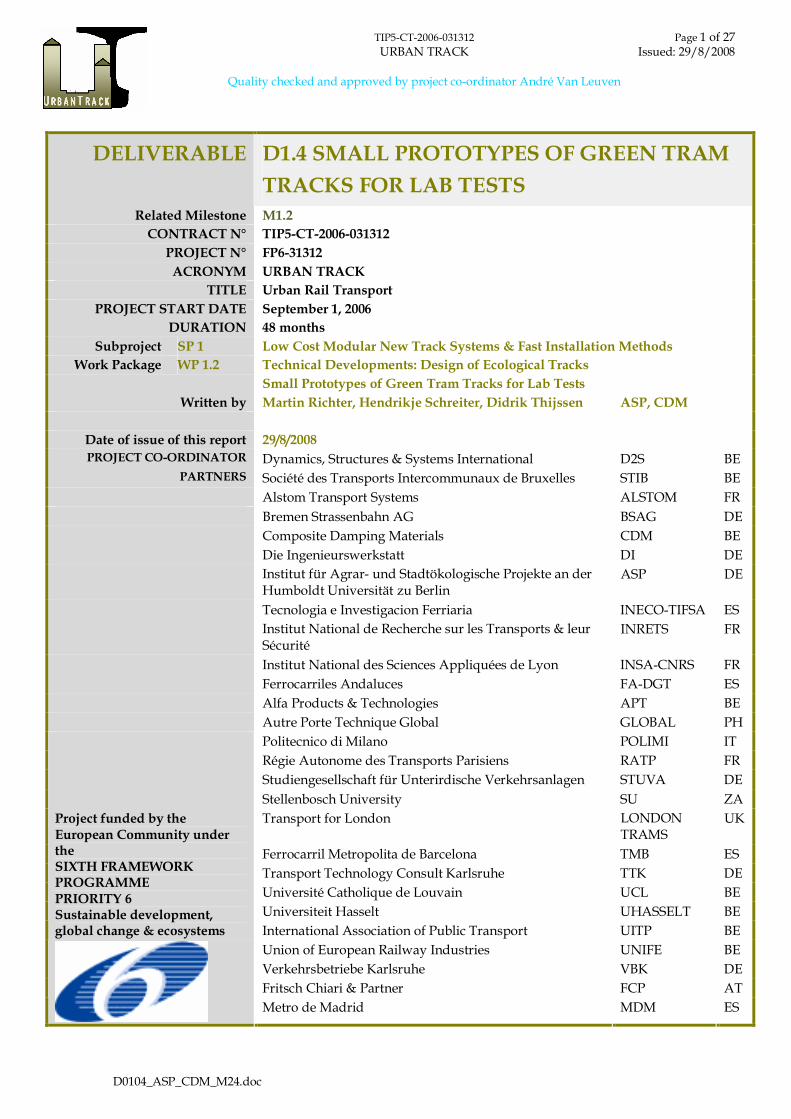
TIP5-CT-2006-031312 Page 1 of 27 URBAN TRACK Issued: 29/8/2008 Quality checked and approved by project co-ordinator André Van Leuven D0104_ASP_CDM_M24.doc DELIVERABLE D1.4 SMALL PROTOTYPES OF GREEN TRAM TRACKS FOR LAB TESTS Related Milestone M1.2 CONTRACT N° TIP5-CT-2006-031312 PROJECT N° FP6-31312 ACRONYM URBAN TRACK TITLE Urban Rail Transport PROJECT START DATE September 1, 2006 DURATION 48 months Subproject SP 1 Low Cost Modular New Track Systems & Fast Installation Methods Work Package WP 1.2 Technical Developments: Design of Ecological Tracks Small Prototypes of Green Tram Tracks for Lab Tests Written by Martin Richter, Hendrikje Schreiter, Didrik Thijssen ASP, CDM Date of issue of this report 29/8/2008 PROJECT CO-ORDINATOR Dynamics, Structures & Systems International D2S BE PARTNERS Société des Transports Intercommunaux de Bruxelles STIB BE Alstom Transport Systems ALSTOM FR Bremen Strassenbahn AG BSAG DE Composite Damping Materials CDM BE Die Ingenieurswerkstatt DI DE Institut für Agrar- und Stadtökologische Projekte an der Humboldt Universität zu Berlin ASP DE Tecnologia e Investigacion Ferriaria INECO-TIFSA ES Institut National de Recherche sur les Transports & leur Sécurité INRETS FR Institut National des Sciences Appliquées de Lyon INSA-CNRS FR Ferrocarriles Andaluces FA-DGT ES Alfa Products & Technologies APT BE Autre Porte Technique Global GLOBAL PH Politecnico di Milano POLIMI IT Régie Autonome des Transports Parisiens RATP FR Studiengesellschaft für Unterirdische Verkehrsanlagen STUVA DE Stellenbosch University SU ZA Transport for London LONDON TRAMS UK Ferrocarril Metropolita de Barcelona TMB ES Transport Technology Consult Karlsruhe TTK DE Université Catholique de Louvain UCL BE Universiteit Hasselt UHASSELT BE Project funded by the European Community under the SIXTH FRAMEWORK PROGRAMME PRIORITY 6 Sustainable development, global change & ecosystems International Association of Public Transport UITP BE Union of European Railway Industries UNIFE BE Verkehrsbetriebe Karlsruhe VBK DE Fritsch Chiari & Partner FCP AT Metro de Madrid MDM ES
Transcript of DELIVERABLE D1.4 SMALL PROTOTYPES OF … Andaluces FA-DGT ES ... Problems Encountered ......
TIP5-CT-2006-031312 Page 1 of 27URBAN TRACK Issued: 29/8/2008
Quality checked and approved by project co-ordinator André Van Leuven
D0104_ASP_CDM_M24.doc
DELIVERABLE D1.4 SMALL PROTOTYPES OF GREEN TRAM
TRACKS FOR LAB TESTS
Related Milestone M1.2
CONTRACT N° TIP5-CT-2006-031312
PROJECT N° FP6-31312
ACRONYM URBAN TRACK
TITLE Urban Rail Transport
PROJECT START DATE September 1, 2006
DURATION 48 months
Subproject SP 1 Low Cost Modular New Track Systems & Fast Installation Methods
Work Package WP 1.2 Technical Developments: Design of Ecological Tracks
Small Prototypes of Green Tram Tracks for Lab Tests
Written by Martin Richter, Hendrikje Schreiter, Didrik Thijssen ASP, CDM
Date of issue of this report 29/8/2008
PROJECT CO-ORDINATOR Dynamics, Structures & Systems International D2S BE
PARTNERS Société des Transports Intercommunaux de Bruxelles STIB BE
Alstom Transport Systems ALSTOM FR
Bremen Strassenbahn AG BSAG DE
Composite Damping Materials CDM BE
Die Ingenieurswerkstatt DI DE
Institut für Agrar- und Stadtökologische Projekte an derHumboldt Universität zu Berlin
ASP DE
Tecnologia e Investigacion Ferriaria INECO-TIFSA ES
Institut National de Recherche sur les Transports & leurSécurité
INRETS FR
Institut National des Sciences Appliquées de Lyon INSA-CNRS FR
Ferrocarriles Andaluces FA-DGT ES
Alfa Products & Technologies APT BE
Autre Porte Technique Global GLOBAL PH
Politecnico di Milano POLIMI IT
Régie Autonome des Transports Parisiens RATP FR
Studiengesellschaft für Unterirdische Verkehrsanlagen STUVA DE
Stellenbosch University SU ZA
Transport for London LONDONTRAMS
UK
Ferrocarril Metropolita de Barcelona TMB ES
Transport Technology Consult Karlsruhe TTK DE
Université Catholique de Louvain UCL BE
Universiteit Hasselt UHASSELT BE
Project funded by theEuropean Community undertheSIXTH FRAMEWORKPROGRAMMEPRIORITY 6Sustainable development,global change & ecosystems International Association of Public Transport UITP BE
Union of European Railway Industries UNIFE BE
Verkehrsbetriebe Karlsruhe VBK DE
Fritsch Chiari & Partner FCP AT
Metro de Madrid MDM ES
TIP5-CT-2006-031312 Page 2 of 27URBAN TRACK Issued: 29/8/2008
Quality checked and approved by project co-ordinator André Van Leuven
D0104_ASP_CDM_M24.doc
T A B L E O F C O N T E N T S
0. Executive Summary ..........................................................................................................................3
0.1. Objective of the Deliverable ..............................................................................................................3
0.2. Strategy Used and/or a Description of the Methods (Techniques) Used with the Justification
Thereof................................................................................................................................................3
0.3. Background Info Available and the Innovative Elements Which Were Developed .....................3
0.4. Problems Encountered ......................................................................................................................4
0.5. Partners Involved and Their Contribution.......................................................................................4
0.6. Conclusions........................................................................................................................................5
1. Introduction.......................................................................................................................................6
2. Description of Prototypes with Sedum Vegetation ......................................................................7
2.1. Structure of Test Bodies.....................................................................................................................8
2.1.1 Grass Paver .....................................................................................................................................9
2.1.2 Substrate..........................................................................................................................................9
2.1.3 Anti Root Foil..................................................................................................................................9
2.1.4 Drainage/Base Layer....................................................................................................................10
2.1.5 Special Absorber ...........................................................................................................................11
2.2. Prototype 1 (Special Absorber – Drain Concrete)..........................................................................14
2.3. Prototype 2 (Special Absorber – Rubber Mat) ...............................................................................16
2.4. Prototype 3 (Grass Paver)................................................................................................................17
3. Description of Prototypes with Artificial Grass..........................................................................19
3.1. Artificial grass..................................................................................................................................19
3.2. Track design.....................................................................................................................................20
3.3. Artificial green track prototypes.....................................................................................................21
4. Tests and Action Performed ..........................................................................................................25
4.1. Pre-cultivation..................................................................................................................................25
4.2. Fatigue Tests ....................................................................................................................................25
5. Tests and Action Planned ..............................................................................................................26
5.1. Noise Measurements at Brussels Test Site .....................................................................................26
6. Problems Encountered ...................................................................................................................27

TIP5-CT-2006-031312 Page 3 of 27URBAN TRACK Issued: 29/8/2008
Quality checked and approved by project co-ordinator André Van Leuven
D0104_ASP_CDM_M24.doc
0. EXECUTIVE SUMMARY
0.1. OBJECTIVE OF THE DELIVERABLE
This deliverable describes prototypes of developed green tram track designs which meet the
requirements of technical standards and come up with solutions to specific problems. Within
the Urban Track project a sustainable, low maintenance, improved noise absorbing, well water
balanced green track with regard to the particular local climate and required technical
standards (stray current) has to be developed, which allows occasional use of emergency
vehicles. Track design, materials and plant varieties influence those parameters, thus were
developed or chosen according to their particular suitability, respectively.
0.2. STRATEGY USED AND/OR A DESCRIPTION OF THE METHODS
(TECHNIQUES) USED WITH THE JUSTIFICATION THEREOF
The strategy is to develop a vegetation system and track design, according to the problems and
requirements of green tram tracks and conducting tests on materials to be considered. Review
and specific tests on applicable materials for green tram tracks regarding their characteristics to
our SWP- objectives were done and have influenced the material choice. Certain parameters of
the developed solutions were further modified and will underlie additional developments
based on the results gained during further tests and the first practical test at Brussels (SP3).
0.3. BACKGROUND INFO AVAILABLE AND THE INNOVATIVE ELEMENTS
WHICH WERE DEVELOPED
Background info available:
- Specifications provided by IASP
- Specifications provided by STIB
- Specifications provided by CDM
Innovative elements:
- low maintenance drivable solution using Sedum.
- with Sedum pre-cultivated grass paver.
- using a better noise absorbing material as rail shoulder than conventional concrete or the
known rubber elements (e.g. from Sedra or Kraiburg).
TIP5-CT-2006-031312 Page 4 of 27URBAN TRACK Issued: 29/8/2008
Quality checked and approved by project co-ordinator André Van Leuven
D0104_ASP_CDM_M24.doc
- preventing excessive weed growth at the connection of the root foils and the sides of the
track by means of inserting the foil end into the concrete board separating the track from
the road and into the longitudinal concrete beam in which the rail is embedded.
- improved quality of last generation artificial grass.
- limiting maintenance and good drivable solution using artificial grass.
0.4. PROBLEMS ENCOUNTERED
IASP
During the fatigue test the drainage material had to be changed, as both split and gravel were to
similar in grit size and therefore not compressible enough. This caused loss of time, with the
effect that firstly only 2 prototypes (version 1) could be tested properly and secondly that this
test only comprised 4,600 wheel crossings. Consequently not all test questions have been
answered.
No suitable grass paver for our pre-cultivation purposes is available on the market. Producers
are not interested in developing a new design at the moment, because of high costs for a new
mold.
Moreover, an industrial bonding of the foil to the sides of the track is needed. It is being tested
at the moment if a pre-cultivation without fleece was feasible.
CDM
It was difficult to simulate the real situation of artificial grass at the test circuit of STUVA. No
real problems have been encountered.
0.5. PARTNERS INVOLVED AND THEIR CONTRIBUTION
CDM basic track design
design of rail jacket and concrete beam
ongoing development of combination of artificial and real vegetation
shared tests (e.g. noise absorption, fatigue test, Brussels test site)
STIB (WP 3.2) operator of Brussels test site
TIP5-CT-2006-031312 Page 5 of 27URBAN TRACK Issued: 29/8/2008
Quality checked and approved by project co-ordinator André Van Leuven
D0104_ASP_CDM_M24.doc
have specific demands on track design
STUVA conduct fatigue test
IASP Development of vegetation system with real plants
0.6. CONCLUSIONS
This deliverable provides input to SP1 and SP3, for those applications were green tram tracks
are planned to be used.
It also has relations with SP4 because of the life cycle cost calculations that have to be
performed.
TIP5-CT-2006-031312 Page 6 of 27URBAN TRACK Issued: 29/8/2008
Quality checked and approved by project co-ordinator André Van Leuven
D0104_ASP_CDM_M24.doc
1. INTRODUCTION
This deliverable describes prototypes of developed green tram track designs which meet the
requirements of technical standards and come up with solutions to specific problems: Within
the Urban Track project a sustainable, low maintenance, improved noise absorbing, well water
balanced green track with regard to the particular local climate and required technical
standards (stray current) has been developed, which allows occasional use of emergency
vehicles. Track design, materials, plant and artificial grass varieties influence those parameters.
They had to be developed or chosen according to their particular suitability.
To ensure the passage of emergency vehicles the developed green tracks must be able to carry
the load of these vehicles. Therefore a fatigue test at STUVA was carried out. For the detailed
description of the test equipment see D2.11 prepeared by STUVA.
TIP5-CT-2006-031312 Page 7 of 27URBAN TRACK Issued: 29/8/2008
Quality checked and approved by project co-ordinator André Van Leuven
D0104_ASP_CDM_M24.doc
2. DESCRIPTION OF PROTOTYPES WITH SEDUMVEGETATION
Three different green tram track prototypes have been developed so far. They are going to be
tested and optimised during SP 3.2. They represent three track design versions which are going
to be put into practice in a test zone in Brussels, each. All three of them aim to reduce as much
reverberant track surface as possible to mitigate noise reflection. These prototypes are built for
fatigue testing at the test site of the project partner STUVA. The test conditions determine the
outer dimensions of the test bodies. The three design versions implement an extensive, thin
layered vegetation system which applies Sedum-moss vegetation. The dimensions of this
system result from plant needs and low maintenance reasons, since the drought tolerant Sedum
only needs fertilizer once a year and survives dry periods better than any other plant or weed
which might start to grow in the track. A more detailed explanation why this vegetation system
was chosen is given in the last progress report for D1.3 (2007). The single elements are described
more detailed in this year’s final deliverable D1.3 (2008). The dimensions of the rail parts (rail,
rubber jacket, concrete foot) are supplied by CDM (see D1.4 from CDM). Design and
dimensions of the prototypes are shown in the figures below.
For the test bodies no plants are used since this does not give additional information.
Steel frame, rail and rail encapsulation of the 6 prototypes were built by CDM and transported
to STUVA where the prototypes were tested for their fatigue stability. Mr. RIFFEL from
HEIDELBERGCEMENT installed drain concrete in 2 prototypes at STUVA test site, which had to
dry for 28 days. IASP did the finish by installing the vegetation system: drainage layer, foil,
grass paver, Xeroterr I (substrate).
The 3 versions were repeated twice (6 test bodies), each repetition filled with either gravel or
split.

TIP5-CT-2006-031312 Page 8 of 27URBAN TRACK Issued: 29/8/2008
Quality checked and approved by project co-ordinator André Van Leuven
D0104_ASP_CDM_M24.doc
2.1. STRUCTURE OF TEST BODIES
Figure 1: Overview of the vegetation system / track design. Left: special noise absorber as hard
shoulder, Right: grass paver up to rubber jacket
Standard structure of the test bodies:
Drainage layer /
base layer
19.5 cm
3 bodies received a split filling (8/16),
3 a gravel filling (8/11);
In later tests the two bodies of version 1 received a mixture of mineral
materials (grit size 0/32)
Anti root foil 0.5 mm
PE
Grass paver 5 cm thick
Fleece (0.2-0.5 mm) glued to the bottom
Filled with 4 cm Xeroterr I (substrate)
Area next to rail
(hard shoulder)
Consisted either of drain concrete (version 1), rubber absorber
(version 2) or grass paver (version 3)
TIP5-CT-2006-031312 Page 9 of 27URBAN TRACK Issued: 29/8/2008
Quality checked and approved by project co-ordinator André Van Leuven
D0104_ASP_CDM_M24.doc
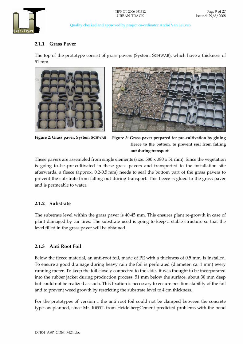
2.1.1 Grass Paver
The top of the prototype consist of grass pavers (System: SCHWAB), which have a thickness of
51 mm.
Figure 2: Grass paver, System SCHWAB Figure 3: Grass paver prepared for pre-cultivation by gluing
fleece to the bottom, to prevent soil from falling
out during transport
These pavers are assembled from single elements (size: 580 x 380 x 51 mm). Since the vegetation
is going to be pre-cultivated in these grass pavers and transported to the installation site
afterwards, a fleece (approx. 0.2-0.5 mm) needs to seal the bottom part of the grass pavers to
prevent the substrate from falling out during transport. This fleece is glued to the grass paver
and is permeable to water.
2.1.2 Substrate
The substrate level within the grass paver is 40-45 mm. This ensures plant re-growth in case of
plant damaged by car tires. The substrate used is going to keep a stable structure so that the
level filled in the grass paver will be obtained.
2.1.3 Anti Root Foil
Below the fleece material, an anti-root foil, made of PE with a thickness of 0.5 mm, is installed.
To ensure a good drainage during heavy rain the foil is perforated (diameter: ca. 1 mm) every
running meter. To keep the foil closely connected to the sides it was thought to be incorporated
into the rubber jacket during production process, 51 mm below the surface, about 30 mm deep
but could not be realized as such. This fixation is necessary to ensure position stability of the foil
and to prevent weed growth by restricting the substrate level to 4 cm thickness.
For the prototypes of version 1 the anti root foil could not be clamped between the concrete
types as planned, since Mr. RIFFEL from HeidelbergCement predicted problems with the bond

TIP5-CT-2006-031312 Page 10 of 27URBAN TRACK Issued: 29/8/2008
Quality checked and approved by project co-ordinator André Van Leuven
D0104_ASP_CDM_M24.doc
of the concrete otherwise. Therefore it was bent down in a 90° angle along the concrete beam
and held by the drainage, more or less.
For the prototypes of version 2 (rubber absorber) the foil was glued to rubber absorber and
concrete beam by means of Sikaflex (SIKA Deutschland GmbH) (see Figure 1, left side). The
bonding was not very tight and resulted in bad bonding of the rubber absorber to the concrete.
During the first fatigue tests the grass paver gave way to the load applied so the rubber
absorber received the full load of the tyre on one side and came off.
For the prototypes of version 3 (grass paver) a slot was cut into the rubber jacket, surrounding
the rail. The foil was pushed into the slot with difficulties and though glued did not clung very
well.
2.1.4 Drainage/Base Layer
For the first fatigue test run the drainage layer of the prototypes was made of gravel with grain
sizes 8/11 mm (version 1-3) as well as of split (8/16), (version 1-3). A more stable behaviour of
split compared to gravel was expected, due to its shape. This layer is usually constructed as fine
plane with a 1% slope towards the middle of the track.
Figure 4: Split (8/16) Figure 5: Gravel (8/11)
Since those materials were not stable enough during the test (neither split nor gravel) they were
replaced by a mixture of mineral materials (0/32) in both prototypes of version 1 (drain
concrete). This material was far more compressible and therefore was stable enough to carry the
load of emergency vehicles (wheel load during fatigue test: 3.5 t).

TIP5-CT-2006-031312 Page 11 of 27URBAN TRACK Issued: 29/8/2008
Quality checked and approved by project co-ordinator André Van Leuven
D0104_ASP_CDM_M24.doc
Figure 6: Mineral mixture (0/32)
2.1.5 Special Absorber
Drain concrete (TioCem)
A new material, drain concrete “TiOCem” developed by HeidelbergCement has been tested
and can be implemented as special absorber.
Figure 7: Drain concrete (HEIDELBERGCEMENT)
Figure 8: Conversion of NOx to NO3- by titanium dioxide and UV-radiation (HEIDELBERGCEMENT)
TIP5-CT-2006-031312 Page 12 of 27URBAN TRACK Issued: 29/8/2008
Quality checked and approved by project co-ordinator André Van Leuven
D0104_ASP_CDM_M24.doc
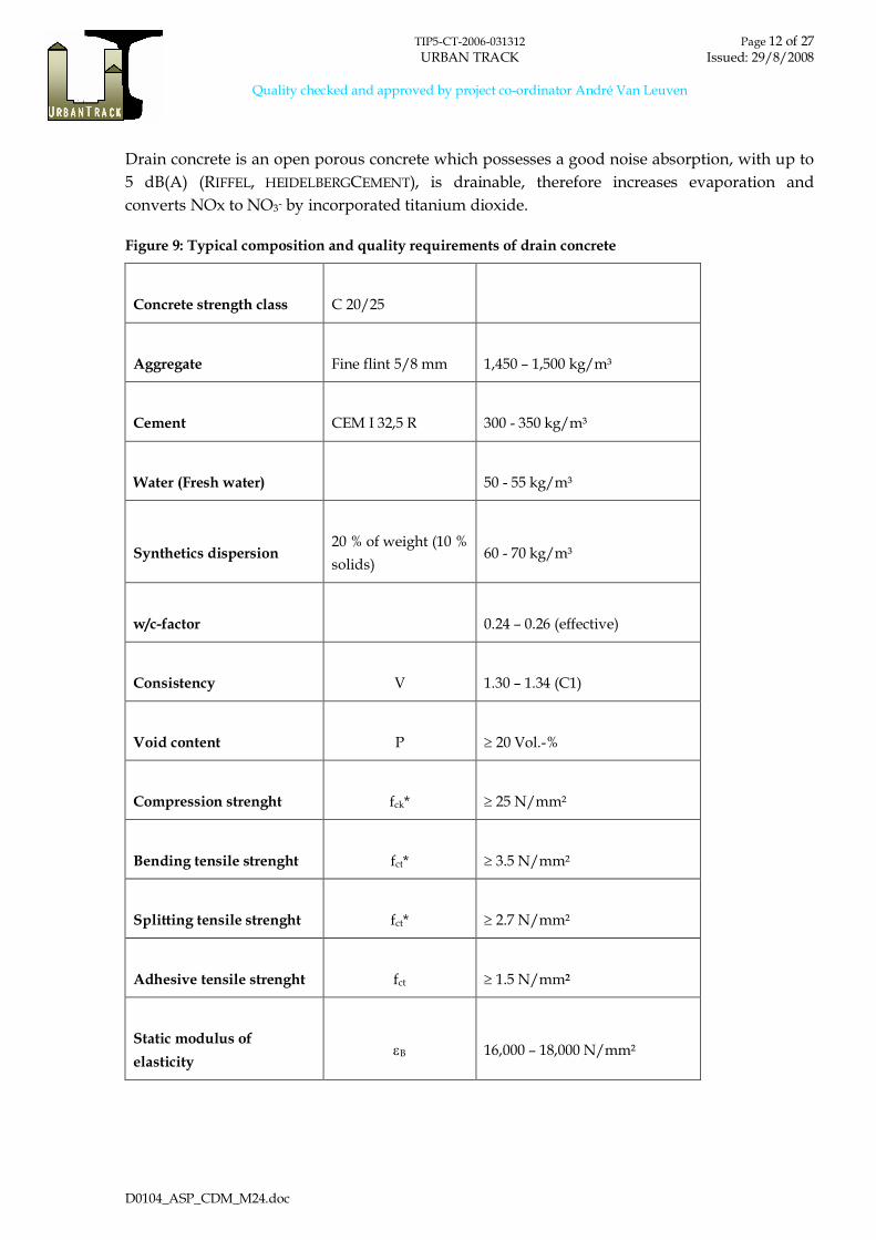
Drain concrete is an open porous concrete which possesses a good noise absorption, with up to
5 dB(A) (RIFFEL, HEIDELBERGCEMENT), is drainable, therefore increases evaporation and
converts NOx to NO3- by incorporated titanium dioxide.
Figure 9: Typical composition and quality requirements of drain concrete
Concrete strength class C 20/25
Aggregate Fine flint 5/8 mm 1,450 – 1,500 kg/m³
Cement CEM I 32,5 R 300 - 350 kg/m³
Water (Fresh water) 50 - 55 kg/m³
Synthetics dispersion20 % of weight (10 %
solids)60 - 70 kg/m³
w/c-factor 0.24 – 0.26 (effective)
Consistency V 1.30 – 1.34 (C1)
Void content P 20 Vol.-%
Compression strenght fck* 25 N/mm²
Bending tensile strenght fct* 3.5 N/mm²
Splitting tensile strenght fct* 2.7 N/mm²
Adhesive tensile strenght fct 1.5 N/mm2
Static modulus of
elasticityB 16,000 – 18,000 N/mm²

TIP5-CT-2006-031312 Page 13 of 27URBAN TRACK Issued: 29/8/2008
Quality checked and approved by project co-ordinator André Van Leuven
D0104_ASP_CDM_M24.doc
Porous rubber (CDM 46)
The CDM porous rubber mat 46 is made of rubber granules of shredded tires which are bonded with a
polyurethane binder under high pressure. During impedance measurements in the previous year this
mat showed the best noise absorption of the tested materials (see progress report D1.3).
Figure 10: Porous rubber mat (CDM 46)
Figure 11: Typical composition and quality requirements of CDM 46
Prescription Unit CDM-46
Material Resin bonded rubber
Colour black
Density - ASTM-D297 kg/m³ 990
Shore hardness -ASTM-D2240 °A 50-60
Tensile strength – ASTM-F152 MPa > 0.5
Elongation at break - ISO-37 % > 40
Compressability at 2.8 MPa – ASTM-F36 % 30-50
Recovery at 2.8 MPa - ASTM-F36 % > 90
Compression set 50%/23°C/70h – DIN53572 % < 10
TIP5-CT-2006-031312 Page 14 of 27URBAN TRACK Issued: 29/8/2008
Quality checked and approved by project co-ordinator André Van Leuven
D0104_ASP_CDM_M24.doc
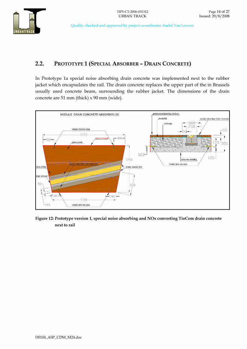
2.2. PROTOTYPE 1 (SPECIAL ABSORBER – DRAIN CONCRETE)
In Prototype 1a special noise absorbing drain concrete was implemented next to the rubber
jacket which encapsulates the rail. The drain concrete replaces the upper part of the in Brussels
usually used concrete beam, surrounding the rubber jacket. The dimensions of the drain
concrete are 51 mm (thick) x 90 mm (wide).
Figure 12: Prototype version 1, special noise absorbing and NOx converting TioCem drain concrete
next to rail

TIP5-CT-2006-031312 Page 15 of 27URBAN TRACK Issued: 29/8/2008
Quality checked and approved by project co-ordinator André Van Leuven
D0104_ASP_CDM_M24.doc
Figure 13: Installation of TioCem drain concrete
Figure 14: 6 empty test bodies for fatigue test,
IASP
Figure 15: Drainage layer filled in (version 3)
Figure 16: Anti root foil (version 2) Figure 17: Fitting of grass paver to test body shape
(version 3)

TIP5-CT-2006-031312 Page 16 of 27URBAN TRACK Issued: 29/8/2008
Quality checked and approved by project co-ordinator André Van Leuven
D0104_ASP_CDM_M24.doc
Figure 18: Drain concrete prototype, ready for testing
2.3. PROTOTYPE 2 (SPECIAL ABSORBER – RUBBER MAT)
Prototype 2 is a variation of Prototype 1. The difference is an additional material (special noise
absorber) implemented next to the rail on top of the concrete which can be used to drive on.
This accommodates operators which prefer a firm shoulder next to the rail. For the prototype
the rubber mat “CDM 46” is used. This material can be prefabricated and installed with lower
efforts than the slightly more noise absorbing drain asphalt. The dimensions of the rubber mat
are 51 mm (thick) x 90 mm (wide).
Figure 19: Prototype version 2, noise absorbing porous rubber mat (CDM 46) as hard shoulder
TIP5-CT-2006-031312 Page 17 of 27URBAN TRACK Issued: 29/8/2008
Quality checked and approved by project co-ordinator André Van Leuven
D0104_ASP_CDM_M24.doc
For the prototypes in version 2 a slot was cut into the rubber jacket, surrounding the rail. The
foil was pushed into the slot with difficulties. The 0.5 mm anti root foil was glued between
absorber and concrete by means of Sikaflex glue. But as already predicted the bonding was not
satisfactory.
Figure 20: Rubber absorber test body, ready for testing
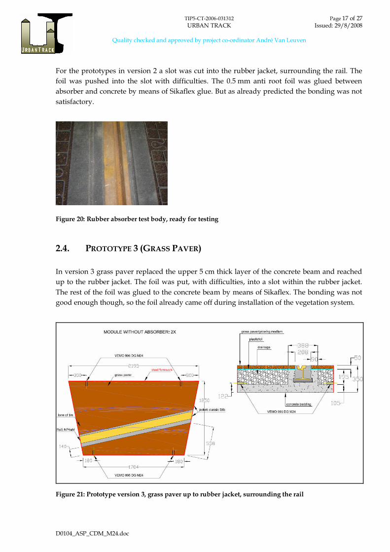
2.4. PROTOTYPE 3 (GRASS PAVER)
In version 3 grass paver replaced the upper 5 cm thick layer of the concrete beam and reached
up to the rubber jacket. The foil was put, with difficulties, into a slot within the rubber jacket.
The rest of the foil was glued to the concrete beam by means of Sikaflex. The bonding was not
good enough though, so the foil already came off during installation of the vegetation system.
Figure 21: Prototype version 3, grass paver up to rubber jacket, surrounding the rail

TIP5-CT-2006-031312 Page 18 of 27URBAN TRACK Issued: 29/8/2008
Quality checked and approved by project co-ordinator André Van Leuven
D0104_ASP_CDM_M24.doc
Figure 22: Test body with grass paver up to rubber jacket, ready for testing

TIP5-CT-2006-031312 Page 19 of 27URBAN TRACK Issued: 29/8/2008
Quality checked and approved by project co-ordinator André Van Leuven
D0104_ASP_CDM_M24.doc
3. DESCRIPTION OF PROTOTYPES WITH ARTIFICIAL GRASS
3.1. ARTIFICIAL GRASS
Artificial grass finishing has the following advantages :
• possibility to install on existing track• low grass maintenance• fast and easy installation• permanently green• low life cycle cost compared to natural grass• good noise absorption• improved quality of last generation artificial grass
The technical specification of the high grade artificial grass CDM used for the prototypes are :
Fibres 100% polyamide, 14.000 dtex
100% monofilament (straight and curled)
Number of knots/m² 17 640/m² +/- 10%
Number of filaments/m² 400 000/m² +/- 10%
Strength of fibres 315N (Pr EN 13864)
Recuperation of fibre after bending 83,5° after 60 min.
Height of fibres 38 mm +/- 5%
Shrinkage height 15 min. at 150°C 2 mm
Withdrawal force fibres 47N (ISO 4919, BS 5229)
Fixation of fibres Latex rubber
Total weight 3 364 gr/m² +/- 5%
Filling No filling necessary
Colour Green (4 ranges of colours)
Colour fastness Scale 7 (DIN 54004)
UV-Stability > 6000 hours (DIN 53387)

TIP5-CT-2006-031312 Page 20 of 27URBAN TRACK Issued: 29/8/2008
Quality checked and approved by project co-ordinator André Van Leuven
D0104_ASP_CDM_M24.doc
Chlor resistance 4-5 (DIN 54019)
Resistance to sea water 4-5 (DIN 54007)
Water permeability 6e4 m/sec
Inflammability Class 1 (DIN 51960)
Toxic fume emission None ITC = 33 (NF X 70-100)
Acoustic absorption coefficient 0,54 at 2037 Hz (tube of Kundt test,
ISO 10534-1)
For the gluing of the grass a Polyurethane based adherent was used. Figure 23 shows the very
realistic looks of the artificial grass.
3.2. TRACK DESIGN
The global track design which will be used for the validation track in Brussels (SP 3.2) is shown
in figure 26. The jacketed rails are embedded in the concrete slab which is covered with the
artificial grass layer. Rain water drainage is guaranteed via sideward inclination of the slab
surfaces.
Figure 23: Looks of a high grade artificial grass sample
TIP5-CT-2006-031312 Page 21 of 27URBAN TRACK Issued: 29/8/2008
Quality checked and approved by project co-ordinator André Van Leuven
D0104_ASP_CDM_M24.doc
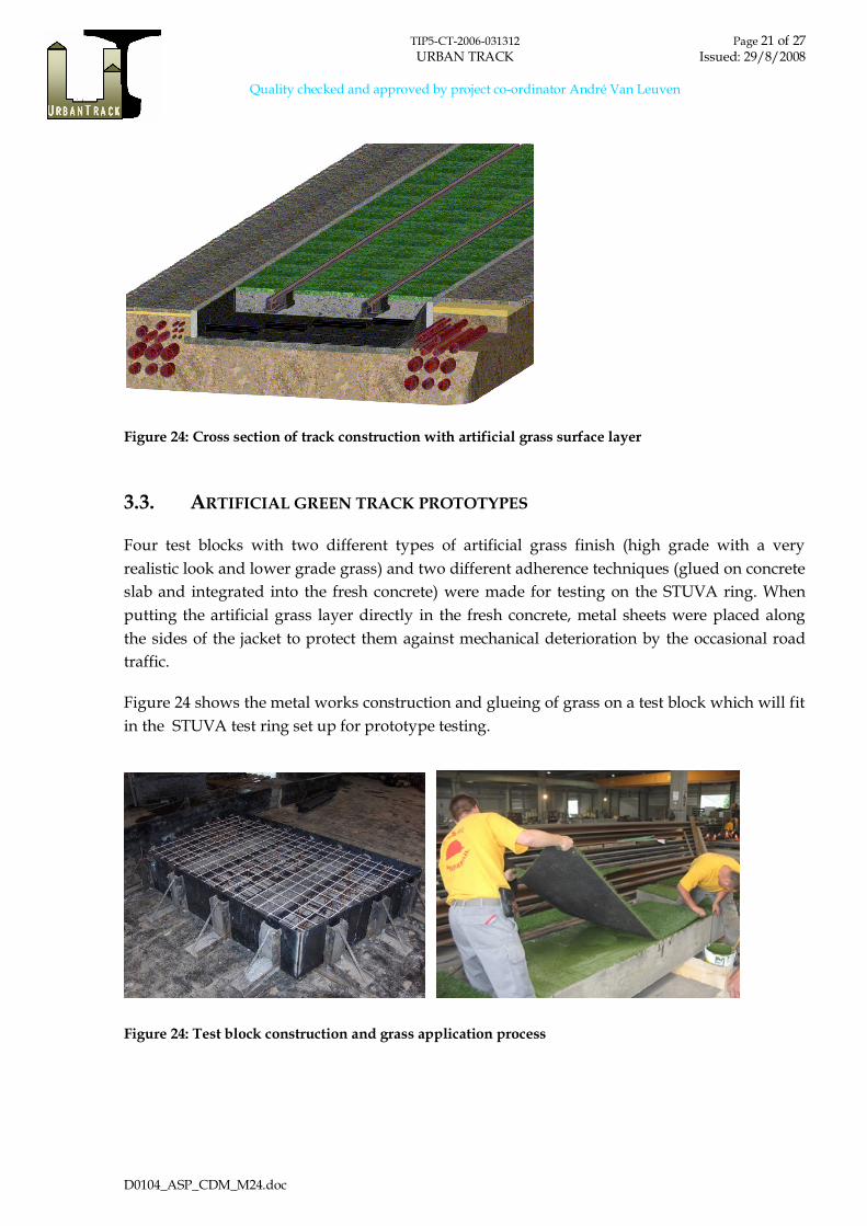
Figure 24: Cross section of track construction with artificial grass surface layer
3.3. ARTIFICIAL GREEN TRACK PROTOTYPES
Four test blocks with two different types of artificial grass finish (high grade with a very
realistic look and lower grade grass) and two different adherence techniques (glued on concrete
slab and integrated into the fresh concrete) were made for testing on the STUVA ring. When
putting the artificial grass layer directly in the fresh concrete, metal sheets were placed along
the sides of the jacket to protect them against mechanical deterioration by the occasional road
traffic.
Figure 24 shows the metal works construction and glueing of grass on a test block which will fit
in the STUVA test ring set up for prototype testing.
Figure 24: Test block construction and grass application process
TIP5-CT-2006-031312 Page 22 of 27URBAN TRACK Issued: 29/8/2008
Quality checked and approved by project co-ordinator André Van Leuven
D0104_ASP_CDM_M24.doc
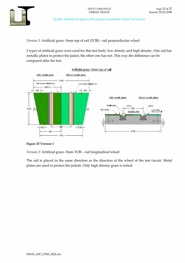
Version 1: Artificial grass -5mm top of rail (TOR) - rail perpendicular wheel
2 types of artificial grass were used for this test body: low density and high density. One rail has
metallic plates to protect the jacket, the other one has not. This way the difference can be
compared after the test.
Figure 25 Version 1
Version 2: Artificial grass -5mm TOR – rail longitudinal wheel
The rail is placed in the same direction as the direction of the wheel of the test circuit. Metal
plates are used to protect the jackets. Only high density grass is tested.
TIP5-CT-2006-031312 Page 23 of 27URBAN TRACK Issued: 29/8/2008
Quality checked and approved by project co-ordinator André Van Leuven
D0104_ASP_CDM_M24.doc
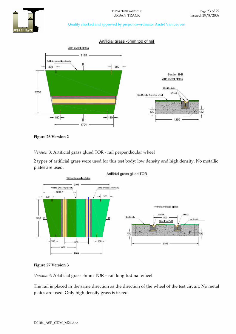
Figure 26 Version 2
Version 3: Artificial grass glued TOR - rail perpendicular wheel
2 types of artificial grass were used for this test body: low density and high density. No metallic
plates are used.
Figure 27 Version 3
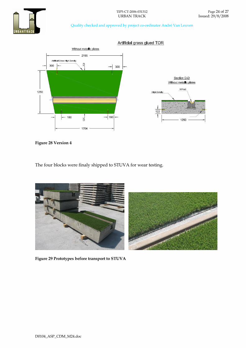
Version 4: Artificial grass -5mm TOR – rail longitudinal wheel
The rail is placed in the same direction as the direction of the wheel of the test circuit. No metal
plates are used. Only high density grass is tested.
TIP5-CT-2006-031312 Page 24 of 27URBAN TRACK Issued: 29/8/2008
Quality checked and approved by project co-ordinator André Van Leuven
D0104_ASP_CDM_M24.doc
Figure 28 Version 4
The four blocks were finaly shipped to STUVA for wear testing.
Figure 29 Prototypes before transport to STUVA
TIP5-CT-2006-031312 Page 25 of 27URBAN TRACK Issued: 29/8/2008
Quality checked and approved by project co-ordinator André Van Leuven
D0104_ASP_CDM_M24.doc
4. TESTS AND ACTION PERFORMED
4.1. PRE-CULTIVATION
During the pre-cultivation process of Sedum in grass paver several questions of practical
realizations appeared and have to be solved. Focus is being laid on an economic production
process to simplify pre-cultivation for further test zones. For further details see D1.3 (2008).
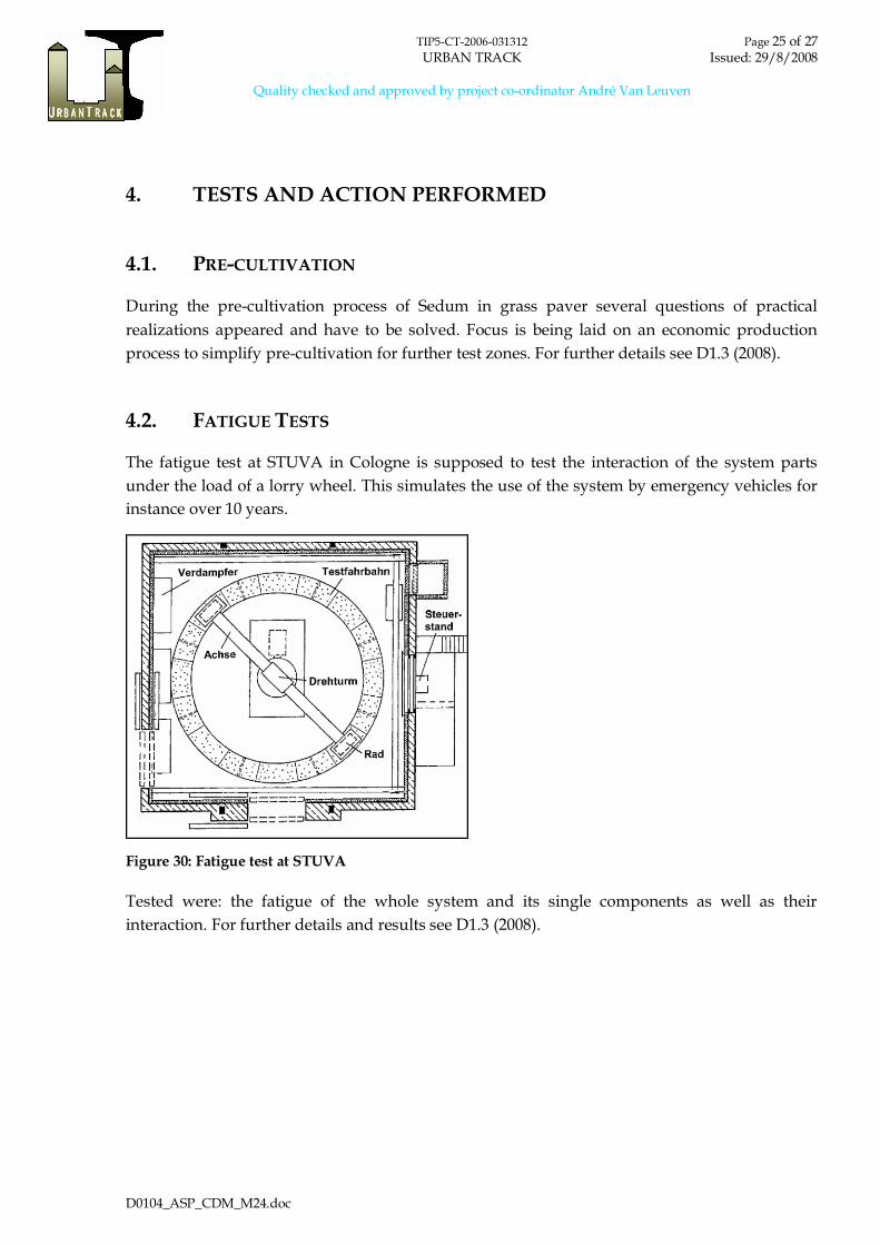
4.2. FATIGUE TESTS
The fatigue test at STUVA in Cologne is supposed to test the interaction of the system parts
under the load of a lorry wheel. This simulates the use of the system by emergency vehicles for
instance over 10 years.
Figure 30: Fatigue test at STUVA
Tested were: the fatigue of the whole system and its single components as well as their
interaction. For further details and results see D1.3 (2008).

TIP5-CT-2006-031312 Page 26 of 27URBAN TRACK Issued: 29/8/2008
Quality checked and approved by project co-ordinator André Van Leuven
D0104_ASP_CDM_M24.doc
5. TESTS AND ACTION PLANNED
5.1. NOISE MEASUREMENTS AT BRUSSELS TEST SITE
At Brussels test site different track designs are going to be tested for noise absorption behaviour
at 4 different zones. Three Sedum versions and one artificial grass version are planned to be
installed and tested. Placing these zones right next to each other a comparison of the noise
absorption behaviour at probably exactly the same conditions can be made.

TIP5-CT-2006-031312 Page 27 of 27URBAN TRACK Issued: 29/8/2008
Quality checked and approved by project co-ordinator André Van Leuven
D0104_ASP_CDM_M24.doc
6. PROBLEMS ENCOUNTERED
IASP
During the fatigue test the drainage material had to be changed, as both split and gravel were to
similar in grit size and therefore not compressible enough. This caused loss of time, with the
effect that firstly only 2 prototypes (version 1) were being tested properly and secondly that this
test only comprised 4600 wheel crossings. Consequently not all test questions have been
answered.
No suitable grass paver for our pre-cultivation purposes is on the market. Producers are not
interested in developing a new design at the moment, because of high costs for a new mould.
Moreover, an industrial bonding of the foil to the sides of the track is needed. It is being tested
at the moment if a pre-cultivation without fleece was feasible.
CDM
None.